1. Introduction
Animal robots are new types of robots that directly control animal movements through human intervention in neural circuit activities. Compared with traditional robot technology, animal robots can rely on the motion functions of biological carriers without carrying additional energy drives. It has shown great advantages in environmental adaptability, concealment, mobility, load capacity, etc [
1,
2].Animal robots has important theoretical and applied value in the fields of neuroscience and engineering, disaster rescue, animal behavior, etc [
3,
4,
5].
Beginning in the 1990s, researchers from various countries have begun research on the use of biological control technology to develop animal robots. For example, the University of Tokyo in Japan conducted related experiments on cockroaches [
6]. The researchers chose to apply electrical stimulation to the best position to control their movement to achieve control, and finally successfully controlled the cockroach to walk straight. In 2006, New Scientist magazine reported that the atema research team of Boston University completed the "Shark Agent" study [
7]. They implanted microelectrodes in the olfactory center of the Squalus acanthias’s brain to generate virtual odor stimuli by electrically stimulating the olfactory center, which induces the shark to swim with odor tracking. In 2007, Su Xuecheng et al. were the first researchers who completed the pigeon navigation [
8]. They used specially processed insulated electrodes to directly stimulate the fear-sensing nucleus to control the pigeon. Finally they were able to control the pigeon to complete take-off and turning. In 2009, researchers at Hiroshima University chose to stimulate the medial longitudinal fasciculus to achieve effective control of goldfish [
9]. In 2015, Erickson et al. from Washington and Lee University, found effective parameters for stimulating cockroaches. The stimulus waveform was bipolar pulse, which realized the behavior of cockroaches moving forward and turning [
10]. In 2017, researches in Seoul National University selected new materials to make electrodes. They chose liquid crystal polymer as the outsourcing material for implantation experiments. They used biphasic current stimulation to finally control the behavior of the pigeons [
11]. In 2019, A handheld neural stimulation controller was proposed in Seoul National University for bird remote navigation. This system consists of a handheld neural stimulation controller and a fully-implanted stimulator [
12]. In the same year, they applied this device to rats and achieved good results [
13].
At present, most of the stimulus signals are regular waveforms such as square waves [
14,
15,
16]. And in each experiment, the stimulus waveform used by the researcher will not change. The long-term use of this simple stimulation mode will produce tolerance in animals, which will greatly reduce the stimulation effect [
17,
18,
19,
20,
21]. Hence, a wireless animal robot stimulation system based on neuronal electrical signal characteristics was proposed in this paper.
2. System Composition
This proposed stimulation system consists of a hardware platform based on STM32, including the signal transmitting base station and the electronic backpack, and a set of GUI. The stimulus commands generated on the GUI are wirelessly sent to the electronic backpack by the transmitting base station. The electronic backpack is carried on the animal and delivers electrical stimulus to electrodes inserted into the animal’s brain.
Figure 1.
Overall system framework.
Figure 1.
Overall system framework.
This paper focuses on simulating animal spikes and increasing the diversity of stimulation patterns. So the DDS algorithm is used in the electronic backpack to decode the stimulation instructions and reconstruct the animal’s analog spike signal. In GUI, we have stored different kinds of spikes collected in advance into the spike library. Users can customize the combination of spikes and generate stimulation parameters from the GUI to send to the electronic backpack. During the stimulation experiment, the user can arbitrarily adjust the stimulation train to increase the variety of stimulation waveforms.
In this paper, details of electronic backpack are demonstrated to show its fabrication methods and the process of spike simulation. The functionality of this system was evaluated in vivo in order to verify the feasibility of using spike signals as stimulus signals.
2.1. Design of Electronic Backpack
Wireless Module
In order not to affect the normal activities of animals, the electronic backpack should use wireless transmission and be small enough. Additionally, low-power but long-range wireless communication is necessary.
To achieve these requirements, CC1101(manufactured by Texas Instruments) has been chosen for wireless communication between the transmitting base station and the electronic backpack. Not only does CC1101 consume lower power than Wi-Fi, it can also transmit data for a longer distance (up to 100 m in practice) in comparison to Bluetooth.
The power consumption of the front-end amplifying part of the radio frequency chip is often the largest. Current conduction angle is reduced to reduce power consumption [
22]. But reducing the current conduction angle will cause harmonic distortion, so a filter was added to solve the above problem. In this paper, the LC filter structure is selected for filtering. The LC filter structure is simple, uses fewer components, and connects the inductor in series in the path, which has better isolation and relatively better filtering effect.
Power Conversion Module
A rechargeable lithium battery (300mAh, 3.7V) is used to power the electronic backpack. REG710-3.3V (manufactured by Texas Instruments) is used to convert the 3.7V into a stable 3.3V for the MCU and CC1101. The voltage converter and multiplexer need ±5V power supply to output the maximum stimulus waveform of ±5V. So REG710-5V is used as voltage boost. The size of this chip is only 2mm × 3mm, which can save a lot of circuit space. A circuit composed of TC7660 and two 10µF tantalum capacitors is used as a negative voltage generating circuit.
Biphasic Pulse Generating Circuit
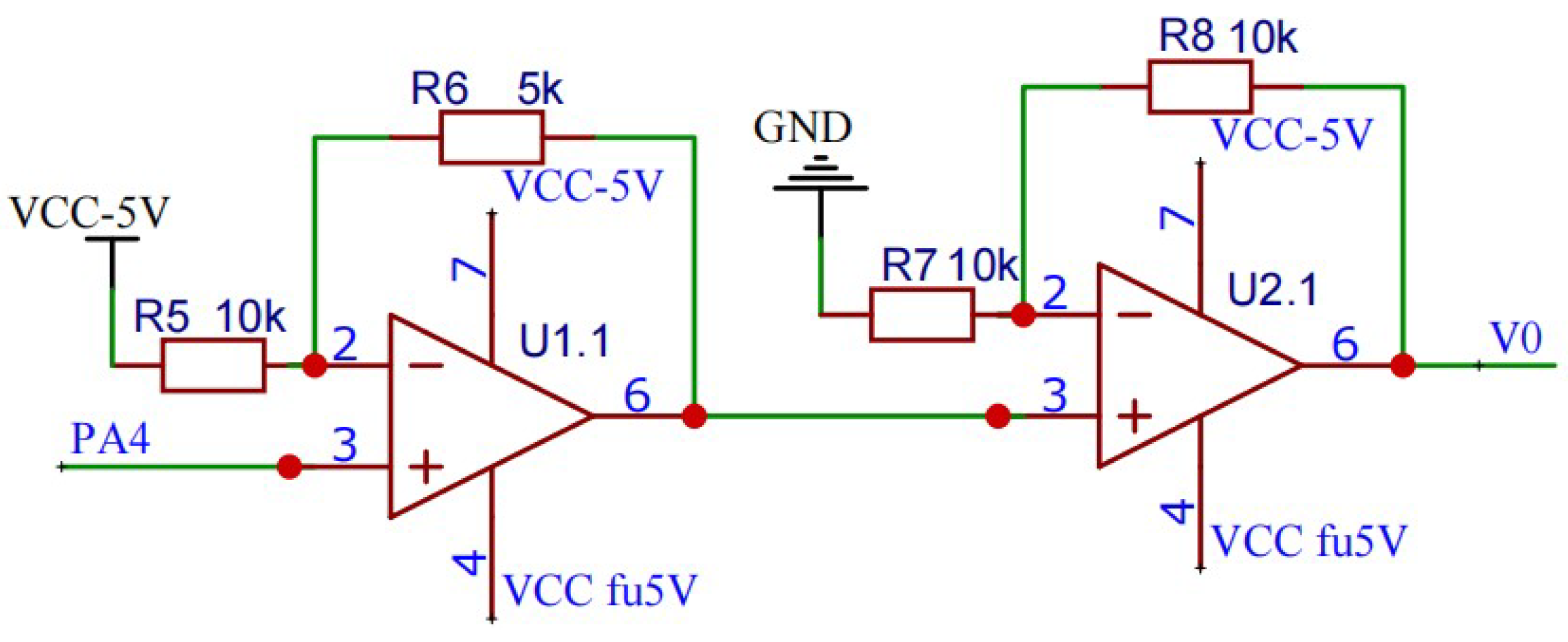
The final analog spike signal to be generated by electronic backpack is a biphasic waveform. The amplitude of the output waveform is adjustable from -5 to 5V. So, a voltage conversion circuit is designed to convert the voltage from 0∼3.3V to -5∼5V voltage. The circuit consists of two operational amplifiers (model AD820), which are used to convert unipolar voltage to bipolar voltage and amplify bipolar voltage respectively. As shown in the
Figure 2.
The output and input have the following relationship:
The electronic backpack decodes and calculates the parameters of the received analog spike signal into a single-phase signal, and then outputs an ideal biphasic analog spike signal through the above-mentioned amplifying circuit.
2.2. PCB Design and Manufacture
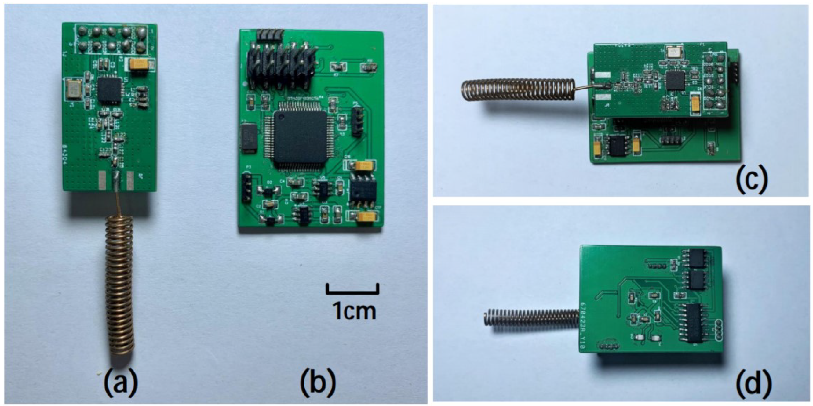
The upper board size is 30mm×16mm×1.5mm, the mass is about 3.7g, the front is CC1101 working circuit and PCB antenna. The lower board is 38mm×23mm×2mm, the mass is about 5.5g, mainly including STM32F103RCT6 working circuit, a REG710 voltage conversion chip, a negative pressure generating TC7660 chip and two AD820 precision op amps. The total weight of the electronic backpack is 15.8g (6.6g including battery). Two rows of 2.54mm pin headers are used to connect between the two circuit boards and realize signal transmission. A rechargeable lithium battery(300mAh, 3.7V) is used as a wireless power source to power the electronic backpack, and the battery is placed between the two circuit boards. The physical map of the entire electronic backpack is shown in
Figure 3.
3. Software Design
Simulating animal spike signals efficiently is our ultimate goal, so Principal Component Analysis (PCA) is used to classify pre-acquired spike data on MATLAB [
23,
24]. Then, the average value of each type of spike data is processed to obtain a smoother curve and the curve is stored as a spike signal. The result is shown in
Figure 4.
The obtained spike potential curve needs to be fitted. The purpose of the fitting is to decompose the spike curve into multiple sinusoidal forms. In the subsequent work, the parameters obtained after fitting need to be sent to the electronic backpack through the GUI. Then, the DDS algorithm is used to process these parameters on the electronic backpack and finally output the analog spike signal. The smoothed spike No.2 as an example, and the fitting result is shown in
Figure 5.
From the results of fitting, the spike No.2 is decomposed into a composite form of four sinusoids. The fitted parameters a, b and c respectively represent the amplitude, frequency, and phase of the decomposed sine (in the yellow box in
Figure 5). The generated fitting parameters are stored in the GUI, and the user can combine and select the desired spike waveform for stimulation in the GUI.
3.1. User Graphical Interface Based on LabVIEW
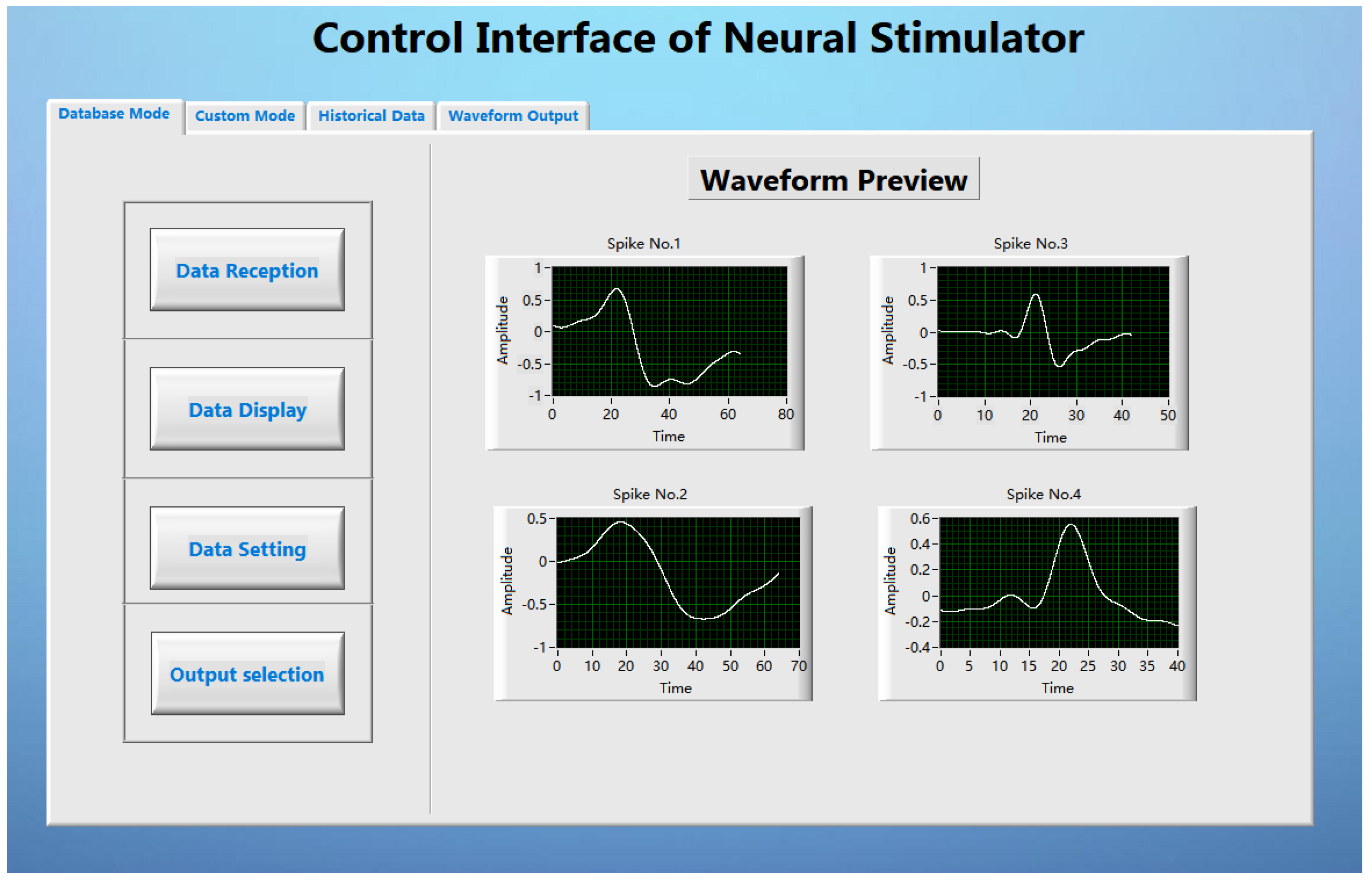
The LabVIEW based user interface is the pivotal part of the stimulus analysis system, which mainly completes the functions of stimulus parameter setting, stimulus command sending and stimulus waveform preview. On the one hand, it stores the data parameters processed by MATLAB in the waveform library; on the other hand, it graphically displays and decodes the parameters and transmits them to the transmitting base station. The GUI performs data transmission with the transmitting base station through the USB interface of the computer. After the system is started, the GUI first checks whether the signal transmitting base station has been connected to the computer, and the GUI starts to run after the detection is successful (as shown in the
Figure 6). The GUI is developed based on LabVIEW. After testing, the interface can complete the established design requirements.
3.2. Direct Digital Synthesizer Algorithms
Using the DDS algorithm to generate analog spike signals through DA and amplifiers is the core solution for generating stimulus signals in this paper. Before this, we have decomposed the original spike signal for the synthesis of several sinusoidal signals, the DDS algorithm can be used to simulate the animal’s spike signal on the hardware more efficiently.
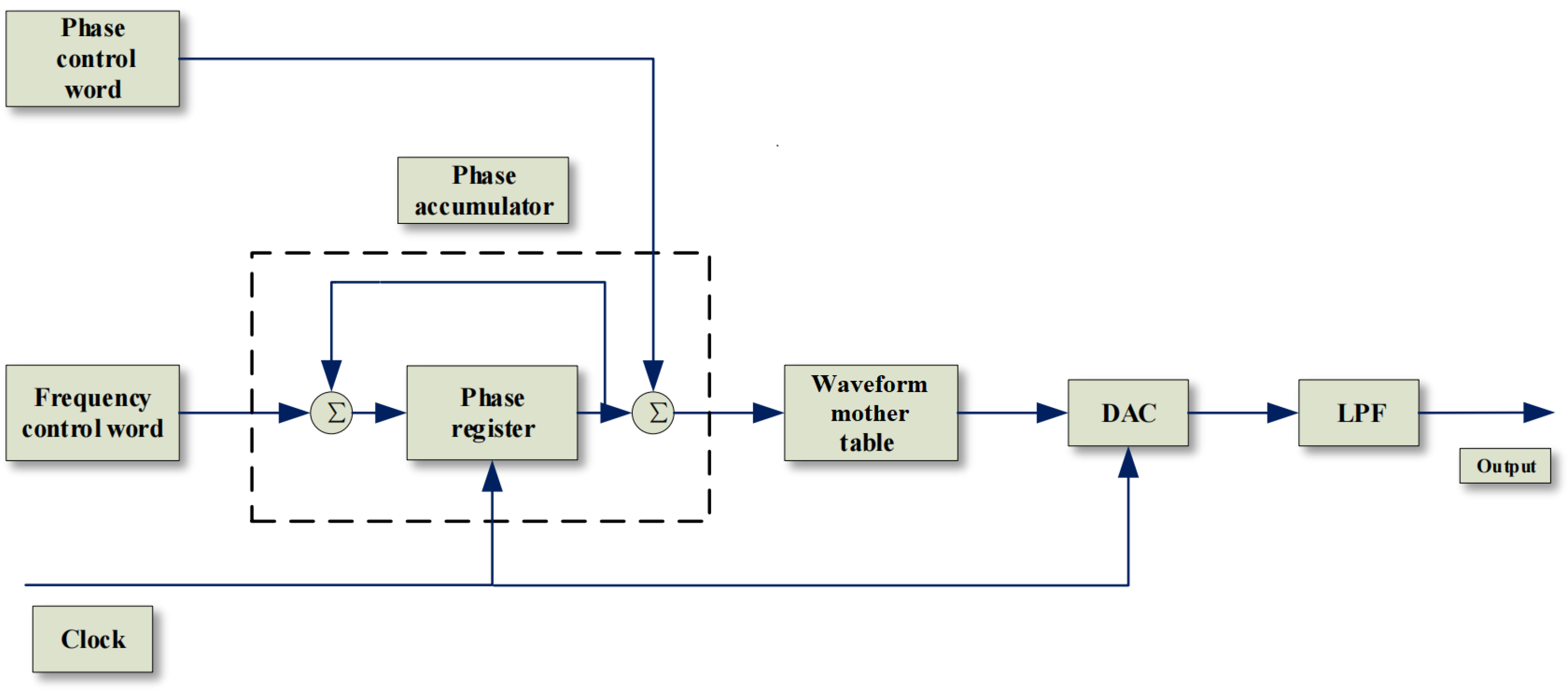
The basic structure of DDS is divided into 5 parts (as shown in the
Figure 7). The first part is the reference clock as the prerequisite for system startup; the core part is the phase accumulator, which controls the output frequency by linearly accumulating the phase value; The third part is the waveform mother table composed of discrete points. The discrete points in the waveform mother table are output as the identification address through the output of the phase accumulator. The remaining two parts are responsible for digital-to-analog conversion and filtering.The realization of the DDS principle and the data synthesis of the waveform mother table are the core of the use of the DDS algorithm to synthesize the spike.
The data receiving end receives a section of four sine function parameters that can fit the spike signal. The main control chip at the receiving end first converts the parameters into four sine data tables, and then obtains the wave code table of the analog spike signal through specific operations. The generated wavecode table can be stored as a waveform mother table for output after algorithm processing.
4. Results
4.1. Stimulus Waveform Verification
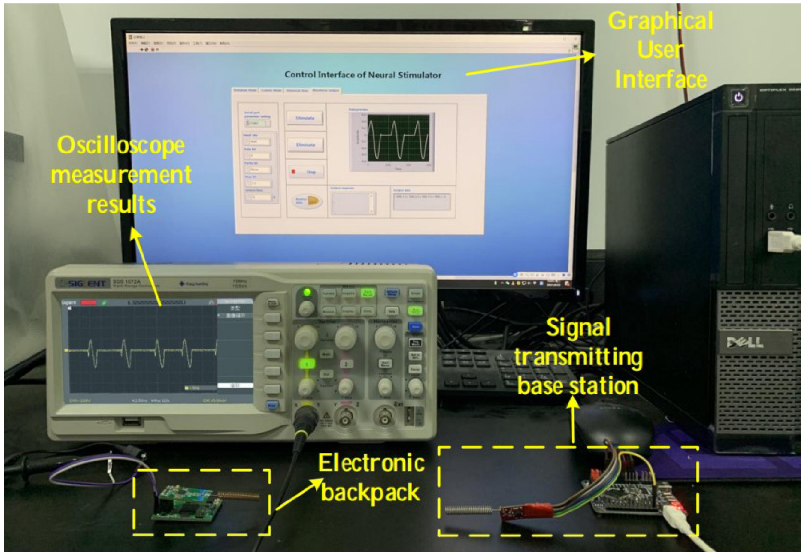
Since this system is a voltage-type control system, it is only necessary to connect the output terminal to the oscilloscope to test the output waveform. According to system requirements, The GUI can provide multiple stimulation modes, that is, it can control the electronic backpack to generate stimulation sequences of arbitrary waveform combinations. The verification of the output waveforms of different stimulus sequences is as follows:
Figure 8.
System test environment.
Figure 8.
System test environment.
In this system, the user can choose to generate a stimulus sequence containing only one kind of spike (at a fixed time interval). After setting the parameters in the user interface, we connect the electronic backpack to the oscilloscope, and the result is shown in the
Figure 9.
The user can also select a stimulus sequence composed of different kinds of spikes, and select up to four kinds of spikes for combination. The frequency, amplitude of the spikes, and the time interval between spikes can all be defined by the user. We chose four different spikes and formed a stimulus sequence for testing. The results are shown in the
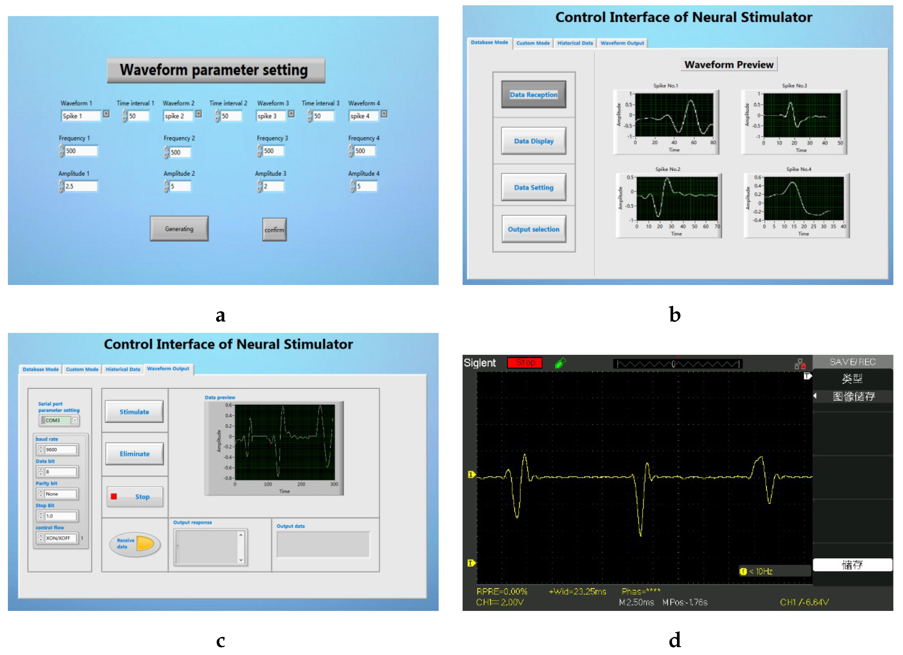
Figure 10.
The user clicks the Data setting button on the main interface to enter the waveform parameter setting interface sub-vi. In this interface, the user can customize the waveform type and other parameters (as shown in
Figure 10a). After returning to the main interface and clicking on the waveform playback, the user can extract the currently set waveform (as shown in
Figure 10b). In the waveform output tab of the main interface, the user can preview and output the current stimulus sequence (as shown in
Figure 10c). After connecting the electronic backpack to the oscilloscope, the parameters of the stimulus sequence we finally tested are consistent with the set waveform parameters (as shown in
Figure 10d).
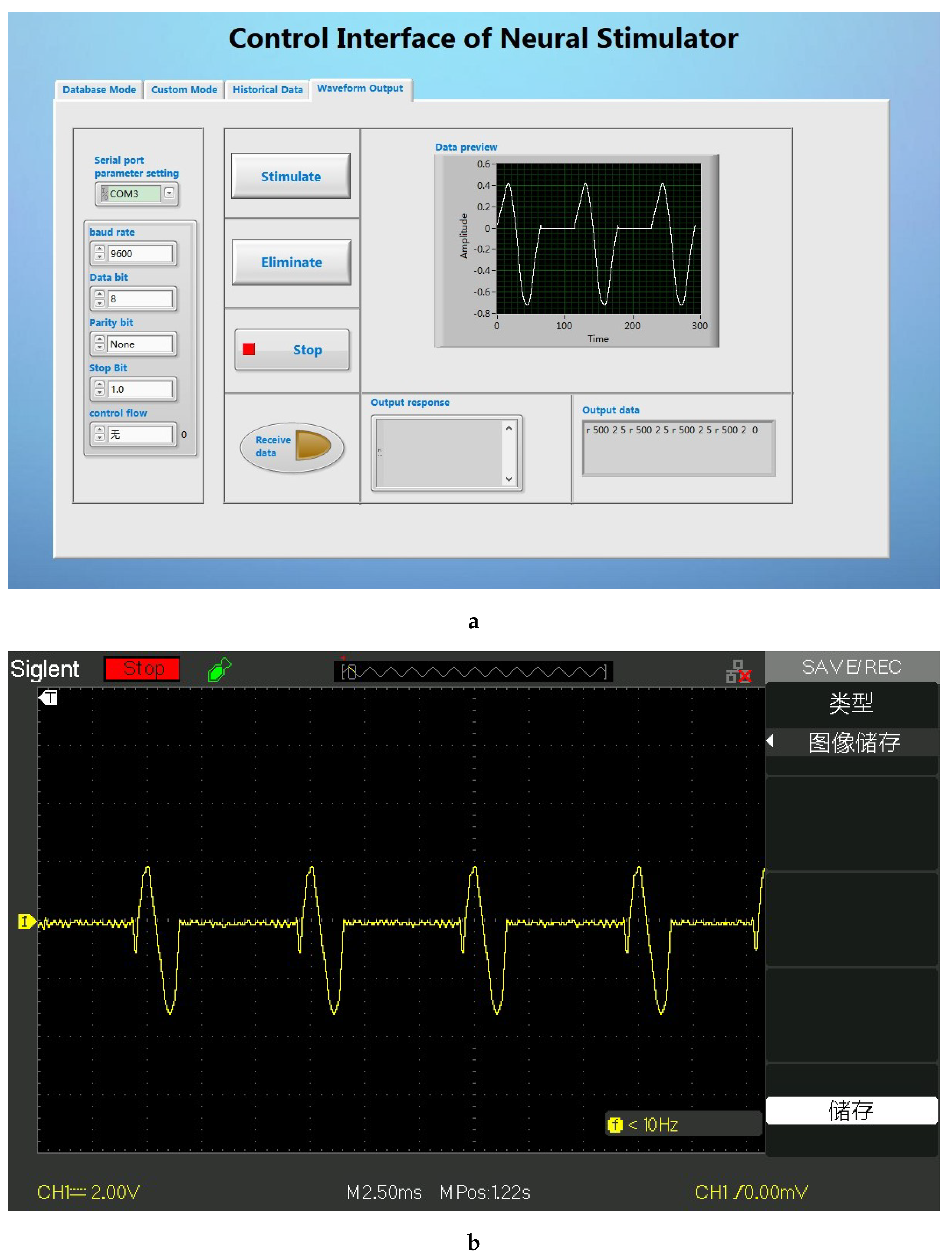
In the custom mode, the user can select the stimulation mode in which different waveforms appear alternately. Here we only participate in the test with a 10ms interval between a square wave and a sine wave, and a 10ms interval between the spike and the square wave. The generated waveform is shown in the
Figure 11.
The results show that the GUI can well complete functions such as waveform selection, stimulation parameter adjustment, and sending stimulation instructions. At the same time, the hardware part can also complete the spike signal output task well. After the waveform output test is completed and the debugging is correct, we can start animal experiments.
4.2. Animal Experiment
Electrode Implantation
In this experiment, microelectrodes are implanted into two motion-related nuclei in the brain: the left and right dorsalis intermedius ventralis anterior (DIVA) nucleus by routine operation [
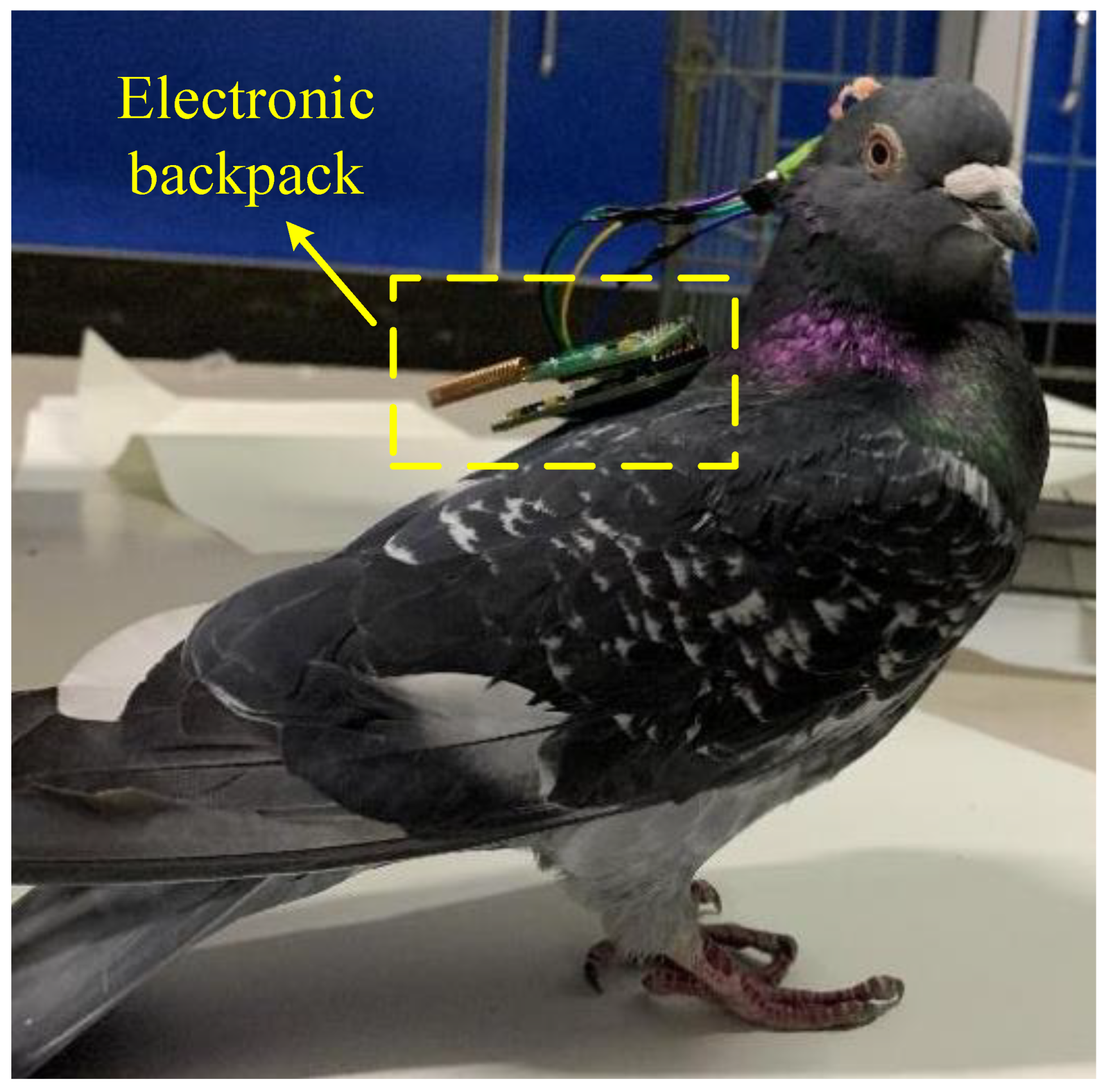
25]. Feed for 5-7 days after the operation, After the pigeon resumes normal behavior and activities, the electronic backpack is inserted and fixed on the pigeon’s head. The output port of the stimulator is connected to the electrode lead-out end, and then the electrical stimulation experiment can be performed.
Figure 12 shows a pigeon undergoing electrical stimulation experiments.
Experimental Results
The stimulator was used to perform stimulation experiments on the two sites of the pigeons, and the most suitable stimulus that can cause the pigeons to react was found. The most suitable stimulus for the two sites is a custom spike combination waveform. The stimulation voltage is 3-5V, and the duration of each spike signal is 2ms, and the time interval between the three spikes is 2ms, that is, every 12ms is a stimulation sequence, repeated 40 times, and the stimulation duration is 480ms in total.
In this paper, 5 pigeons are selected for the experiment, the stimulation is repeated 10 times, and the above-mentioned spike combination waveform is used as the stimulus signal. The results of the experiment are shown in the
Table 1. In actual operation, 4 pigeons can basically perform left-right turn reaction according to the control requirements, and the success rate can reach more than 75%. There was 1 animal with a low success rate within the appropriate voltage stimulation range. The reason may be a deviation of the implant position during the electrode implantation or the electrode lead falling off after the pigeon returned to activity.
The experimental results show that the most suitable stimulation voltage range is 3-5V when using the above-mentioned spike stimulation waveform for stimulation. When the voltage is 3V, the pigeons start to turn left and right. As the voltage increases, the reaction of the pigeons becomes more violent, and the success rate of the left and right turns becomes higher. At this time, the pigeons show obvious behavior of evading and turning.
5. Conclusion
In this paper, a wireless animal robot stimulation system based on neuronal electrical signal characteristics is designed. It is no longer limited to using the same waveform for stimulation, but uses analog spikes with spike signal characteristics for stimulation. In order to increase stimulation modes, a mixed form of a variety of stimulation modes are provided, which can be customized to select the spike waveform or the regular waveform to form the desired stimulation sequence. DDS algorithm is used to reconstruct the original spike parameters into analog spike signals to enrich the stimulation waveform in the field of animal robot.
In order to verify the reliability of the system, we used pigeons as the research object to verify the system. From the experimental results, our system is easy to operate and reliable in communication. The communication range can cover every corner of the room, and the communication reliability rate is over 90%. At the same time, the system is small in size and light in weight, and has little impact on the movement of pigeons, which improves the efficiency and success rate of the experiment. In addition, the stimulus signal generated by the system based on the DDS principle to simulate the electrical signal characteristics of the neuron. It successfully caused the pigeon’s stress response. Indicating that the simulation of the action potential signal of the animal’s neuron as a stimulus signal is feasible in the control of animal robots. At the same time, the multi-modal stimulation used by this system breaks the traditional stimulation method and increases the stimulation mode of the animal robot. This stimulus method provides effective ideas and methods for solving the problem of "stimulation fatigue" in the future.
Acknowledgments
This study was funded by the National Natural Science Foundation of China (61903230), the Natural Science Foundation of Shandong Province (ZR2020MF098).
References
- Zhou, Z.; Liu, D.; Sun, H.; Xu, W.; Tian, X.; Li, X.; Cheng, H.; Wang, Z. Pigeon robot for navigation guided by remote control: system construction and functional verification. Journal of Bionic Engineering 2021, 18, 184–196. [Google Scholar] [CrossRef]
- Sato, H.; Berry, C.W.; Casey, B.E.; Lavella, G.; Yao, Y.; VandenBrooks, J.M.; Maharbiz, M.M. A cyborg beetle: insect flight control through an implantable, tetherless microsystem. 2008 IEEE 21st International Conference on Micro Electro Mechanical Systems. IEEE, 2008, pp. 164–167.
- Nguyen, H.D.; Tan, P.Z.; Sato, H.; Vo-Doan, T.T. Sideways walking control of a cyborg beetle. IEEE Transactions on Medical Robotics and Bionics 2020, 2, 331–337. [Google Scholar] [CrossRef]
- Jia, Y.; Guler, U.; Lai, Y.P.; Gong, Y.; Weber, A.; Li, W.; Ghovanloo, M. A trimodal wireless implantable neural interface system-on-chip. IEEE transactions on biomedical circuits and systems 2020, 14, 1207–1217. [Google Scholar] [CrossRef] [PubMed]
- Edward, E.S.; Kouzani, A.Z.; Tye, S.J. Towards miniaturized closed-loop optogenetic stimulation devices. Journal of neural engineering 2018, 15, 021002. [Google Scholar] [CrossRef] [PubMed]
- Holzer, R.; Shimoyama, I. Locomotion control of a bio-robotic system via electric stimulation. Proceedings of the 1997 IEEE/RSJ International Conference on Intelligent Robot and Systems. Innovative Robotics for Real-World Applications. IROS’97. IEEE, 1997, Vol. 3, pp. 1514–1519.
- Brown, S. Stealth sharks to patrol the high seas. New scientist 2006, 189, 30–31. [Google Scholar]
- XueCheng, S.; RuiTuo, H.; JunQing, Y.; Hui, W.; ChangZhi, L. Brain mechanism and methods for robo-animal motor behavior control. Scientia Sinica Informationis 2012, 42, 1130–1146. [Google Scholar]
- Kobayashi, N.; Yoshida, M.; Matsumoto, N.; Uematsu, K. Artificial control of swimming in goldfish by brain stimulation: confirmation of the midbrain nuclei as the swimming center. Neuroscience letters 2009, 452, 42–46. [Google Scholar] [CrossRef] [PubMed]
- Erickson, J.C.; Herrera, M.; Bustamante, M.; Shingiro, A.; Bowen, T. Effective stimulus parameters for directed locomotion in Madagascar hissing cockroach biobot. PloS one 2015, 10, e0134348. [Google Scholar] [CrossRef] [PubMed]
- Shim, S.; Yun, S.; Kim, S.; Choi, G.J.; Baek, C.; Jang, J.; Jung, Y.; Sung, J.; Park, J.H.; Seo, K.; others. A handheld neural stimulation controller for avian navigation guided by remote control. Bio-medical materials and engineering 2019, 30, 497–507. [Google Scholar] [CrossRef]
- Yun, S.; Koh, C.S.; Jeong, J.; Seo, J.; Ahn, S.H.; Choi, G.J.; Shim, S.; Shin, J.; Jung, H.H.; Chang, J.W.; others. Remote-controlled fully implantable neural stimulator for freely moving small animal. Electronics 2019, 8, 706. [Google Scholar] [CrossRef]
- Seo, J.; Choi, G.J.; Park, S.; Lee, J.; Baek, C.; Jang, J.; Lim, J.; Shin, S.; Seo, K.; Seo, J.M. Wireless navigation of pigeons using polymer-based fully implantable stimulator: a pilot study using depth electrodes. 2017 39th Annual International Conference of the IEEE Engineering in Medicine and Biology Society (EMBC). IEEE, 2017, pp. 917–920.
- Lin, Y.J.; Lee, S.Y. A microstimulator with parameter adjustment for bladder dysfunction. 2017 IEEE International Symposium on Circuits and Systems (ISCAS). IEEE, 2017, pp. 1–4.
- Seo, J.; Wee, J.H.; Park, J.H.; Park, P.; Kim, J.W.; Kim, S.J. Nerve cuff electrode using embedded magnets and its application to hypoglossal nerve stimulation. Journal of neural engineering 2016, 13, 066014. [Google Scholar] [CrossRef] [PubMed]
- Potter, K.A.; Buck, A.C.; Self, W.K.; Capadona, J.R. Stab injury and device implantation within the brain results in inversely multiphasic neuroinflammatory and neurodegenerative responses. Journal of neural engineering 2012, 9, 046020. [Google Scholar] [CrossRef] [PubMed]
- Chestek, C.A.; Gilja, V.; Nuyujukian, P.; Foster, J.D.; Fan, J.M.; Kaufman, M.T.; Churchland, M.M.; Rivera-Alvidrez, Z.; Cunningham, J.P.; Ryu, S.I.; others. Long-term stability of neural prosthetic control signals from silicon cortical arrays in rhesus macaque motor cortex. Journal of neural engineering 2011, 8, 045005. [Google Scholar] [CrossRef] [PubMed]
- Kozai, T.D.Y.; Langhals, N.B.; Patel, P.R.; Deng, X.; Zhang, H.; Smith, K.L.; Lahann, J.; Kotov, N.A.; Kipke, D.R. Ultrasmall implantable composite microelectrodes with bioactive surfaces for chronic neural interfaces. Nature materials 2012, 11, 1065–1073. [Google Scholar] [CrossRef] [PubMed]
- Sanchez, J.C.; Alba, N.; Nishida, T.; Batich, C.; Carney, P.R. Structural modifications in chronic microwire electrodes for cortical neuroprosthetics: a case study. IEEE transactions on neural systems and rehabilitation engineering 2006, 14, 217–221. [Google Scholar] [CrossRef] [PubMed]
- Purcell, E.K.; Thompson, D.E.; Ludwig, K.A.; Kipke, D.R. Flavopiridol reduces the impedance of neural prostheses in vivo without affecting recording quality. Journal of neuroscience methods 2009, 183, 149–157. [Google Scholar] [CrossRef] [PubMed]
- Jia, Y.; Mirbozorgi, S.A.; Lee, B.; Khan, W.; Madi, F.; Inan, O.T.; Weber, A.; Li, W.; Ghovanloo, M. A mm-sized free-floating wirelessly powered implantable optical stimulation device. IEEE transactions on biomedical circuits and systems 2019, 13, 608–618. [Google Scholar] [CrossRef] [PubMed]
- Hennig, M.H.; Hurwitz, C.; Sorbaro, M. Scaling spike detection and sorting for next-generation electrophysiology. In Vitro Neuronal Networks 2019, pp. 171–184.
- Vallicelli, E.A.; De Matteis, M.; Baschirotto, A.; Rescati, M.; Reato, M.; Maschietto, M.; Vassanelli, S.; Guarrera, D.; Collazuol, G.; Zeiter, R. Neural spikes digital detector/sorting on FPGA. 2017 IEEE Biomedical Circuits and Systems Conference (BioCAS). IEEE, 2017, pp. 1–4.
- Chen, L.; Sun, Q.; Zhao, Y.; Wang, C. Design and Experiments of a Waveform Generator Based on DDS Technology. Recent Patents on Engineering 2020, 14, 588–597. [Google Scholar] [CrossRef]
- Wild, J.M. The avian somatosensory system: connections of regions of body representation in the forebrain of the pigeon. Brain Research 1987, 412, 205–223. [Google Scholar] [CrossRef] [PubMed]
|
Disclaimer/Publisher’s Note: The statements, opinions and data contained in all publications are solely those of the individual author(s) and contributor(s) and not of MDPI and/or the editor(s). MDPI and/or the editor(s) disclaim responsibility for any injury to people or property resulting from any ideas, methods, instructions or products referred to in the content. |
© 2023 by the authors. Licensee MDPI, Basel, Switzerland. This article is an open access article distributed under the terms and conditions of the Creative Commons Attribution (CC BY) license (http://creativecommons.org/licenses/by/4.0/).

