Submitted:
17 January 2023
Posted:
18 January 2023
You are already at the latest version
Abstract
Keywords:
I. Introduction
II. Fundamentals of Integrated Sagnac Interference Devices
2. Modeling of Complex Integrated Sagnac Interference Devices
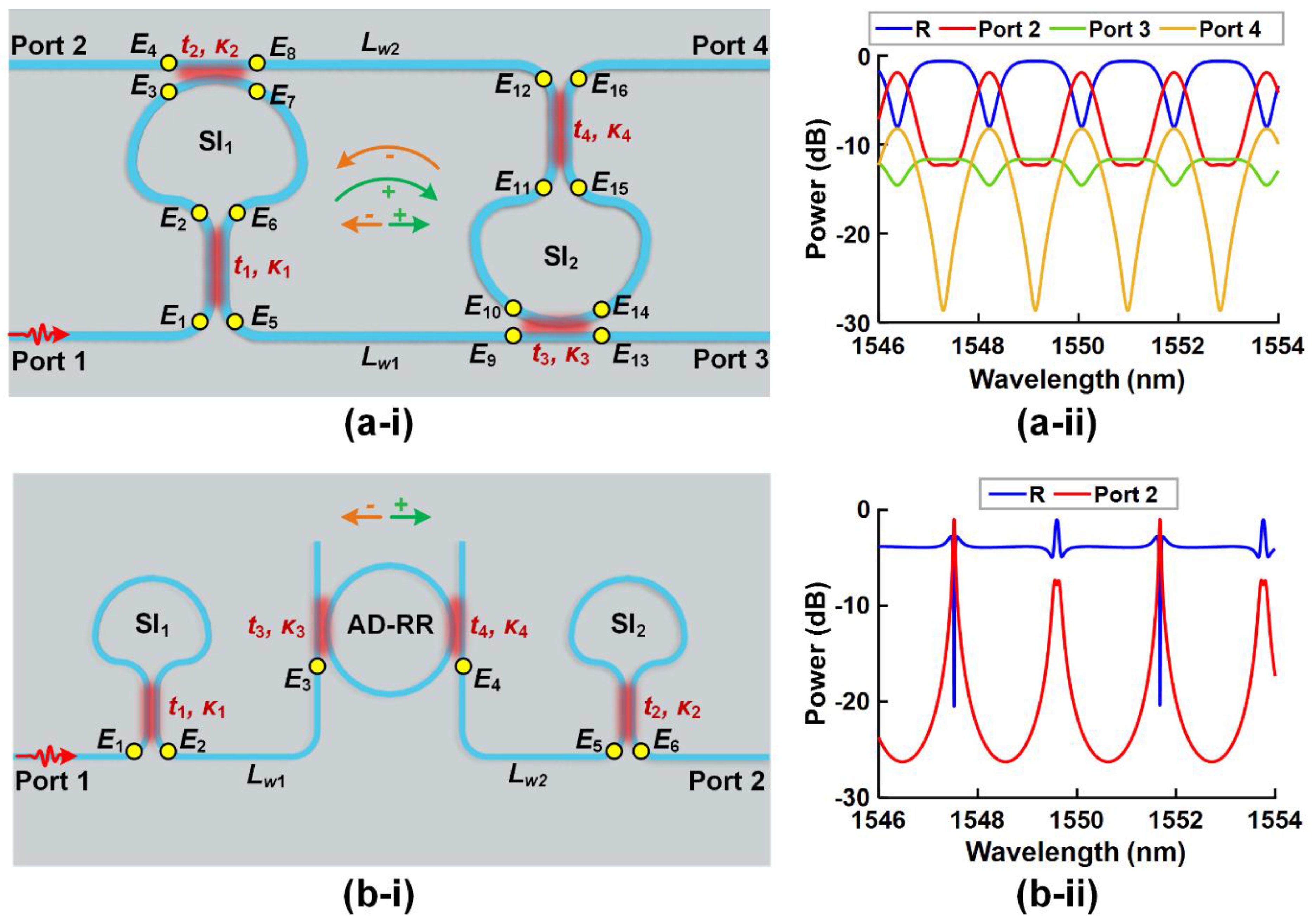
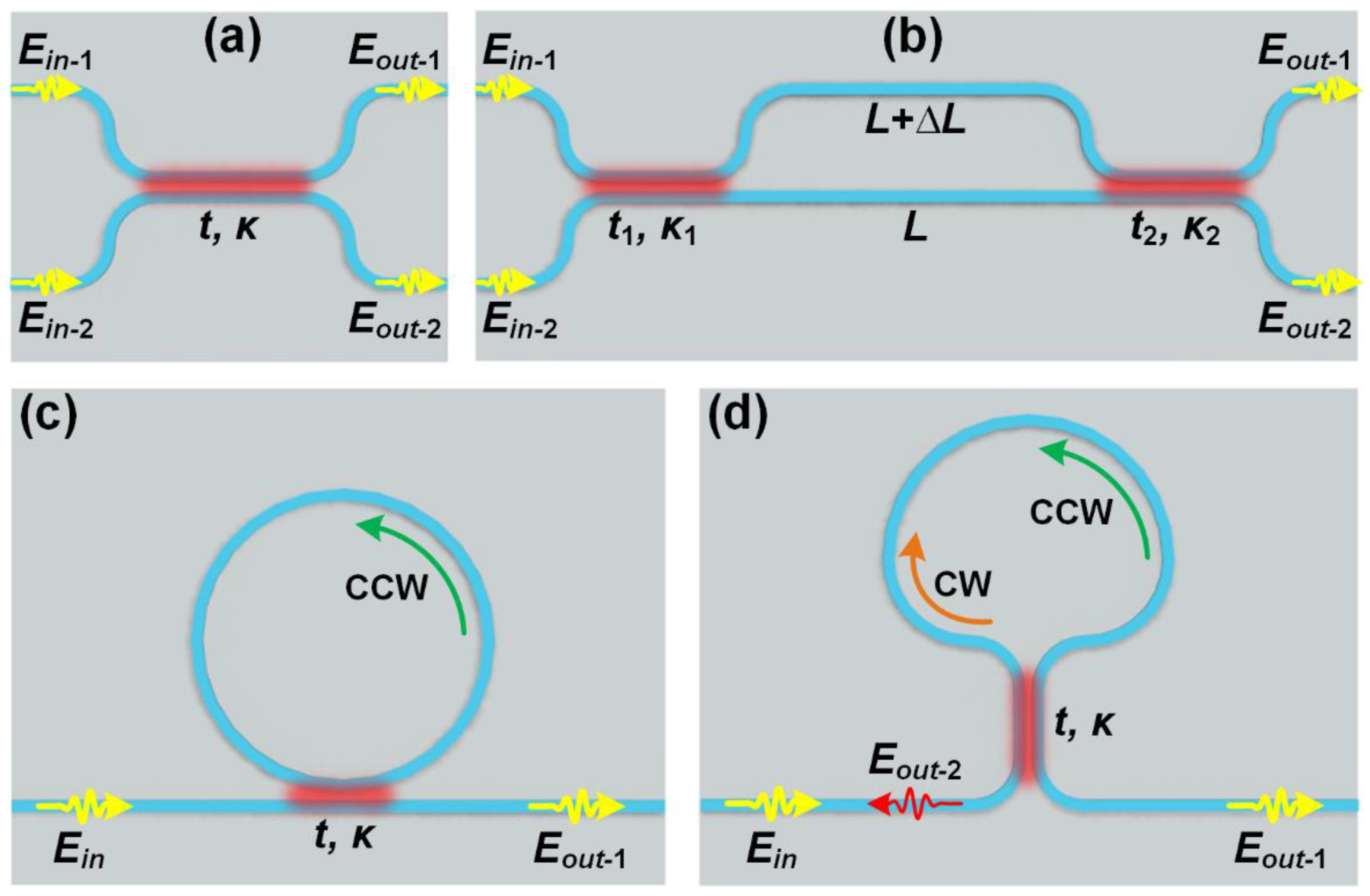
1. Waveguide Sagnac interferometers and other integrated building blocks
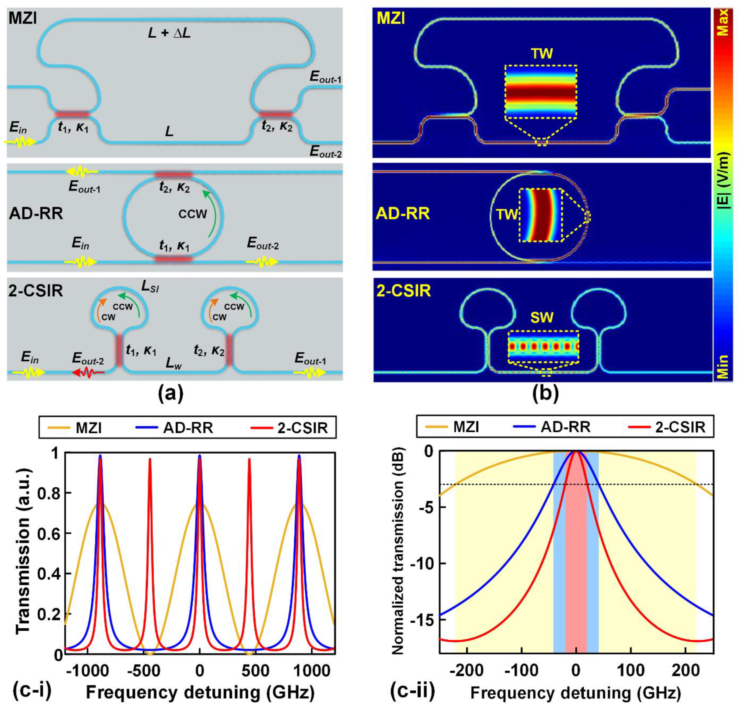
3. Device design and tuning
III. Integrated Sagnac interference devices
1. Reflection Mirrors
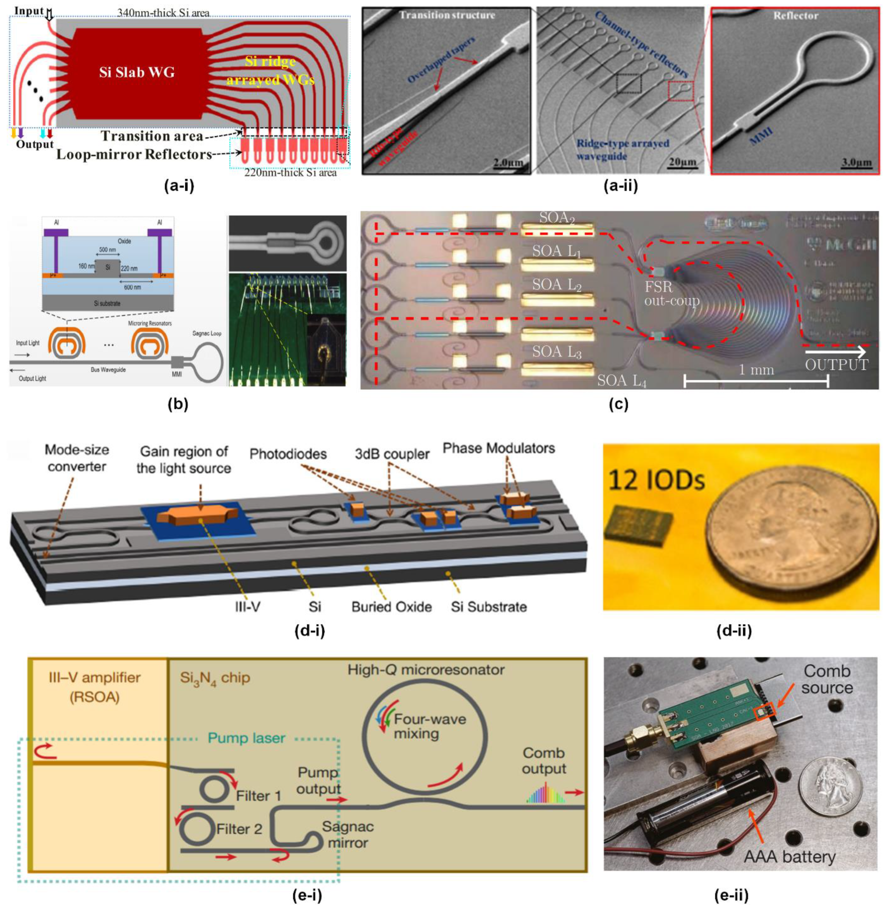
2. Optical Gyroscopes
A. Interferometric optical gyroscopes (IOGs)
B. Passive resonant optical gyroscopes (PROGs)
C. Brillouin ring laser gyroscopes (BRLGs)
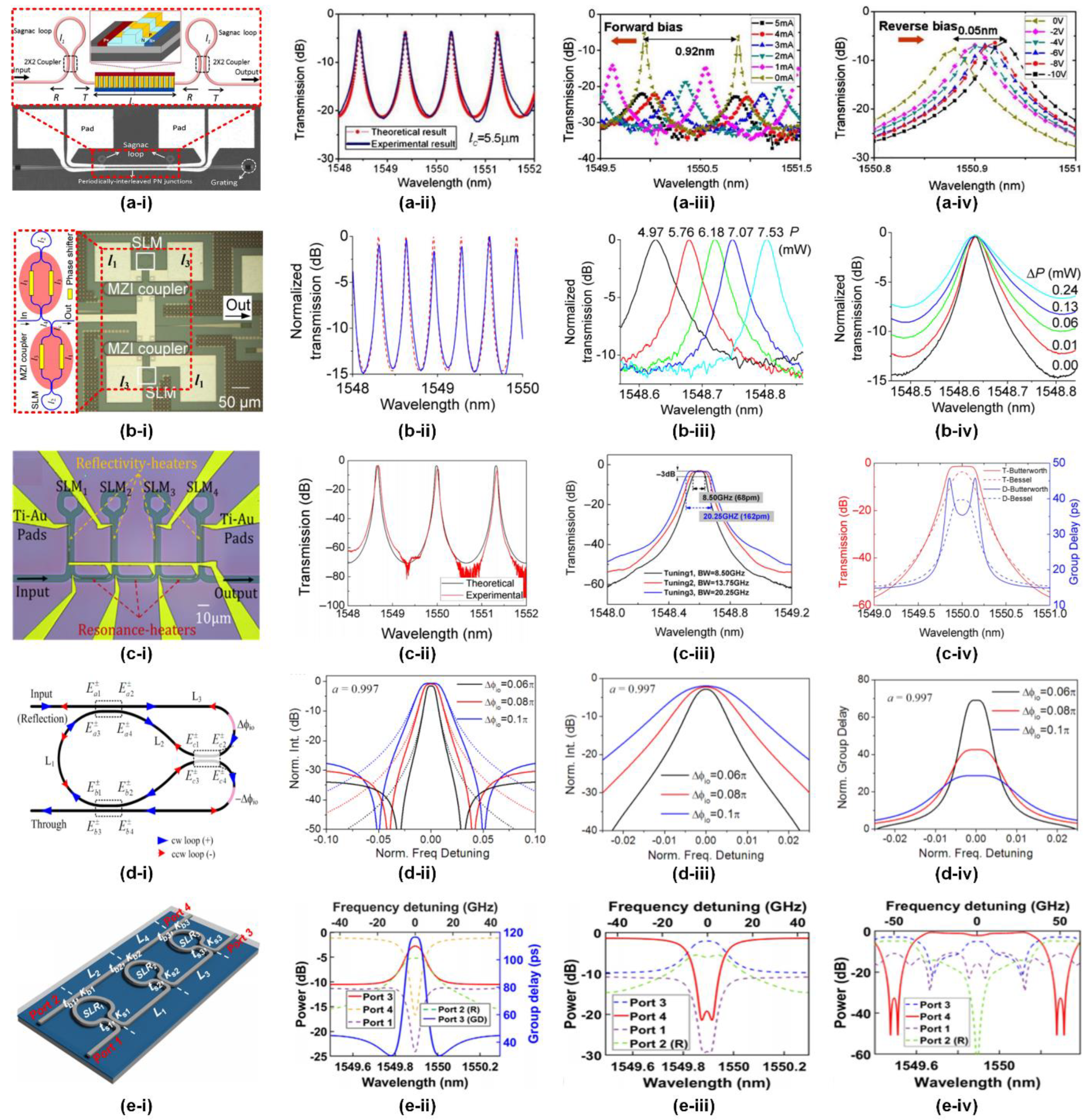
3. Basic filters
| Filter name | Key characteristics of spectral response | Non-Sagnac interference device | Sagnac interference device |
|---|---|---|---|
| Comb filter | With an amplitude response consisting of a series of regularly spaced notches or peaks that resemble a comb. | [175,176,177] | [100,174,178,179,180] |
| Butterworth filter | With a flat bandpass amplitude response | [181,182,183] | [56,180,184,185,186,187,188] |
| Bessel filter | With a linear phase response (i.e., constant group delay) over the amplitude passband | [181,189] | [180,184,185,187,188] |
| Chebyshev Type I filter | With passband ripples and flat stopband response | [181,190,191] | [187,188] |
| Chebyshev Type II filter | With stopband ripples and flat passband response | [190,191,192] | [187] |
| Elliptic filter | With ripples in both passband and stopband, thus providing the steepest roll-off than other types of filters. | [191,192] | [187] |
4. Wavelength (de)interleavers
| Device structure | Integrated platform |
Device footprint (μm2) |
ER (dB) |
CS (GHz) |
IL (dB) |
Ref. | |
|---|---|---|---|---|---|---|---|
| 7 coupled SIs | SOI | ~320 × 150 | ~20 | ~100 | ~8.0 | [194] | |
| 4 cascaded SIs | SOI | ~125 × 376 | ~20 | ‒ | ~6.0 | [201] | |
| 2 cascaded SIs in a Saganc interfering loop | SOI | ~120 × 60 | ~25 | ‒ | ~7.3 | [200] | |
| 2 cascaded SIs with MZI couplers in a Saganc interfering loop | SOI | ~736 × 523 | ~20 | ‒ | ~6.0 | [179] | |
| 1D-PhC FP cavity in a Saganc interfering loop | SOI | ~64 × 70 | ~20 | ~2370 | ~0.5 | [202] | |
| A MZI structure with cascaded SIs in the two arms | N/A a) | N/A a) | ~29 | ~50 | ~1.0 | [186] | |
| 2 parallel SIs coupled to a bus waveguide | N/A a) | N/A a) | ~32 | ~50 | ~0.8 | [72] | |
| 2 coupled SIs with a feedback loop | N/A a) | N/A a) | ~13 | ‒ | ~0.4 | [203] | |
5. Optical Analogues of Quantum Physics
6. Other Applications
IV. Challenges and perspectives
V. Conclusion
Conflicts of Interest
References
- Hanbury Brown, R. The intensity interferometer. Its applications to astronomy; London, Taylor & Francis; New York, Halsted Press: 1974.
- Monnier, J.D. Optical interferometry in astronomy. Reports on Progress in Physics 2003, 66, 789. [Google Scholar] [CrossRef]
- Labeyrie, A.; Lipson, S.G.; Nisenson, P. An Introduction to Optical Stellar Interferometry; Cambridge University Press: Cambridge, 2010. [Google Scholar] [CrossRef]
- Islam, M.; Ali, M.M.; Lai, M.-H.; Lim, K.-S.; Ahmad, H. Chronology of Fabry-Perot interferometer fiber-optic sensors and their applications: a review. Sensors 2014, 14, 7451–7488. [Google Scholar] [CrossRef] [PubMed]
- Mitra, B.; Shelamoff, A.; Booth, D. An optical fibre interferometer for remote detection of laser generated ultrasonics. Measurement Science and Technology 1998, 9, 1432. [Google Scholar] [CrossRef]
- Caber, P.J. Interferometric profiler for rough surfaces. Appl Opt 1993, 32, 3438–3441. [Google Scholar] [CrossRef] [PubMed]
- De Groot, P.; Deck, L. Surface profiling by analysis of white-light interferograms in the spatial frequency domain. Journal of modern optics 1995, 42, 389–401. [Google Scholar] [CrossRef]
- Dionisio, R.P. Interferometry applications in all-optical communications networks. Optical Interferometry 2017, 167. [Google Scholar]
- Berry, D.W.; Wiseman, H.M. Quantum optics on a chip. Nature Photonics 2009, 3, 317–319. [Google Scholar] [CrossRef]
- Chekhova, M.; Ou, Z. Nonlinear interferometers in quantum optics. Advances in Optics and Photonics 2016, 8, 104–155. [Google Scholar] [CrossRef]
- Gao, Y.; Gan, Q.; Xin, Z.; Cheng, X.; Bartoli, F.J. Plasmonic Mach–Zehnder interferometer for ultrasensitive on-chip biosensing. ACS nano 2011, 5, 9836–9844. [Google Scholar] [CrossRef]
- Santos, A.; Balderrama, V.S.; Alba, M.; Formentín, P.; Ferré-Borrull, J.; Pallarès, J.; Marsal, L.F. Tunable Fabry-Pérot interferometer based on nanoporous anodic alumina for optical biosensing purposes. Nanoscale research letters 2012, 7, 1–4. [Google Scholar] [CrossRef]
- Bachalo, W.; Houser, M. Optical interferometry in fluid dynamics research. Optical Engineering 1985, 24, 243455. [Google Scholar] [CrossRef]
- van Delft, K.M.; Eijkel, J.C.; Mijatovic, D.; Druzhinina, T.S.; Rathgen, H.; Tas, N.R.; van den Berg, A.; Mugele, F. Micromachined Fabry− Pérot interferometer with embedded nanochannels for nanoscale fluid dynamics. Nano letters 2007, 7, 345–350. [Google Scholar] [CrossRef]
- Kaschke, M.; Donnerhacke, K.-H.; Rill, M.S. Optical devices in ophthalmology and optometry: technology, design principles and clinical applications; Wiley-VCH Verlag GmbH & Co. KGaA: 2014. [CrossRef]
- Françon, M. Optical interferometry. In Neutron interferometry, 1979.
- Kreis, T. Handbook of holographic interferometry: optical and digital methods; John Wiley & Sons: 2006.
- Young, T., II. The Bakerian Lecture. On the theory of light and colours. Philosophical transactions of the Royal Society of London 1802, 12–48. [Google Scholar]
- Young, T., I. The Bakerian Lecture. Experiments and calculations relative to physical optics. Philosophical transactions of the Royal Society of London 1804, 1–16. [Google Scholar]
- Born, M.A.X.; Wolf, E. Chapter VII - elements of the theory of interference and interferometers. In Principles of Optics (Sixth Edition), Born, M.A.X., Wolf, E., Eds. Pergamon: 1980. 256–369. [CrossRef]
- Banishev, A.; Wang, J.; Bhowmick, M. Optical Interferometry; IntechOpen: 2017.
- Lloyd, H. On a New Case of Interference of the Rays of Light. The Transactions of the Royal Irish Academy 1831, 17, 171–177. [Google Scholar]
- Hariharan, P. Basics of Interferometry Second ed.; Academic Press: Burlington, 2007. [Google Scholar] [CrossRef]
- Sagnac, G. L'éther lumineux démontré par l'effet du vent relatif d'éther dans un interféromètre en rotation uniforme. CR Acad. Sci. 1913, 157, 708–710. [Google Scholar]
- Post, E.J. Sagnac effect. Reviews of Modern Physics 1967, 39, 475. [Google Scholar] [CrossRef]
- Rosenthal, A.H. Regenerative circulatory multiple-beam interferometry for the study of light-propagation effects. JOSA 1962, 52, 1143–1148. [Google Scholar] [CrossRef]
- Macek, W.M.; Davis Jr, D. Rotation Rate Sensing with Traveling-Wave Ring Lasers. Applied Physics Letters 1963, 2, 67–68. [Google Scholar] [CrossRef]
- Stedman, G.; Schreiber, K.; Bilger, H. On the detectability of the Lense–Thirring field from rotating laboratory masses using ring laser gyroscope interferometers. Classical and Quantum Gravity 2003, 20, 2527. [Google Scholar] [CrossRef]
- Stedman, G.; Hurst, R.; Schreiber, K. On the potential of large ring lasers. Optics Communications 2007, 279, 124–129. [Google Scholar] [CrossRef]
- Schreiber, K.U.; Klügel, T.; Wells, J.-P.; Hurst, R.; Gebauer, A. How to detect the chandler and the annual wobble of the earth with a large ring laser gyroscope. Physical Review Letters 2011, 107, 173904. [Google Scholar] [CrossRef]
- Bosi, F.; Cella, G.; Di Virgilio, A.; Ortolan, A.; Porzio, A.; Solimeno, S.; Cerdonio, M.; Zendri, J.; Allegrini, M.; Belfi, J. Measuring gravitomagnetic effects by a multi-ring-laser gyroscope. Physical Review D 2011, 84, 122002. [Google Scholar] [CrossRef]
- Udd, E. Applications Of The Fiber Optic Sagnac Interferometer (O-E/Fiber LASE '88). SPIE: 1989.
- Culshaw, B. The optical fibre Sagnac interferometer: an overview of its principles and applications. Measurement Science and Technology 2005, 17, R1. [Google Scholar] [CrossRef]
- Lefevre, H.C. The Fiber-Optic Gyroscope, Second Edition; Artech House Publishers: 2014.
- Brown, R.B. NRL Memorandum Report 1871; Naval Research Laboratory, Washington, D.C, 1968; pp 19-22.
- Birks, T.A.; Morkel, P. Jones calculus analysis of single-mode fiber Sagnac reflector. Appl Opt 1988, 27, 3107–3113. [Google Scholar] [CrossRef] [PubMed]
- Mortimore, D.B. Fiber loop reflectors. Journal of lightwave technology 1988, 6, 1217–1224. [Google Scholar] [CrossRef]
- Miller, L.D.; Mortimore, D.B.; Urquhart, P.; Ainslie, B.J.; Craig, S.P.; Millar, C.A.; Payne, D.B. A Nd(3+)-doped cw fiber laser using all-fiber reflectors. Appl Opt 1987, 26, 2197–2201. [Google Scholar] [CrossRef] [PubMed]
- Dyott, R.; Handerek, V.; Bello, J. Polarization holding directional couplers using D fiber. In Proceedings of Fiber Optic Couplers, Connectors, and Splice Technology; pp. 23-29. International Society for Optics and Photonics.
- Kao, K.C.; Hockham, G.A. Dielectric-fibre surface waveguides for optical frequencies. In Proceedings of Proceedings of the Institution of Electrical Engineers; pp. 1151–1158.
- Vali, V.; Shorthill, R.W. Fiber ring interferometer. Appl Opt 1976, 15, 1099–1100. [Google Scholar] [CrossRef] [PubMed]
- Ezekiel, S.a.K., G. E. Laser Inertial Rotation Sensors; Society of Photo-optical Instrumentation Engineers: Bellingham, WA, USA, 1978; Volume 157. [Google Scholar]
- Chow, W.; Gea-Banacloche, J.; Pedrotti, L.; Sanders, V.; Schleich, W.; Scully, M. The ring laser gyro. Reviews of Modern Physics 1985, 57, 61. [Google Scholar] [CrossRef]
- Lefevre, H.C. The fiber-optic gyroscope; Artech house: 2014.
- Moan, E.; Horne, R.; Arpornthip, T.; Luo, Z.; Fallon, A.; Berl, S.; Sackett, C. Quantum rotation sensing with dual Sagnac interferometers in an atom-optical waveguide. Physical review letters 2020, 124, 120403. [Google Scholar] [CrossRef]
- Du, J.; Shu, C. Cascaded and multisection Sagnac interferometers for scalable and tunable all-optical OFDM DEMUX. Journal of lightwave technology 2013, 31, 2307–2313. [Google Scholar]
- Kuzin, E.A.; Ibarra Escamilla, B.; Garcia-Gomez, D.E.; Haus, J.W. Fiber laser mode locked by a Sagnac interferometer with nonlinear polarization rotation. Opt Lett 2001, 26, 1559–1561. [Google Scholar] [CrossRef]
- Ibarra-Escamilla, B.; Kuzin, E.; Gomez-Garcia, D.; Gutierrez-Zainos, F.; Mendoza-Vazquez, S.; Haus, J. A mode-locked fibre laser using a Sagnac interferometer and nonlinear polarization rotation. Journal of Optics A: Pure and Applied Optics 2003, 5, S225. [Google Scholar] [CrossRef]
- Starodumov, A.; Zenteno, L.; Monzon, D.; De La Rosa, E. Fiber Sagnac interferometer temperature sensor. Applied Physics Letters 1997, 70, 19–21. [Google Scholar] [CrossRef]
- Ma, J.; Yu, Y.; Jin, W. Demodulation of diaphragm based acoustic sensor using Sagnac interferometer with stable phase bias. Opt. Express 2015, 23, 29268–29278. [Google Scholar] [CrossRef] [PubMed]
- Bouyer, P. The centenary of Sagnac effect and its applications: From electromagnetic to matter waves. Gyroscopy and Navigation 2014, 5, 20–26. [Google Scholar] [CrossRef]
- 2010 Pioneer Award. IEEE Transactions on Aerospace and Electronic Systems 2011, 47, 2289–2299. [CrossRef]
- Napoli, J. 20 years of KVH fiber optic gyro technology: the evolution from large, low performance FOGs to compact, precise FOGs and FOG-based inertial systems (SPIE Commercial + Scientific Sensing and Imaging). SPIE, 2016.
- Udd, E.; Udd Scheel, I. Mars or bust! 40 years of fiber optic sensor development (SPIE Commercial + Scientific Sensing and Imaging). SPIE, 2017.
- Wu, X.; Tong, L. Optical microfibers and nanofibers. Nanophotonics 2013, 2, 407–428. [Google Scholar] [CrossRef]
- Wu, J.; Moein, T.; Xu, X.; Moss, D.J. Advanced photonic filters based on cascaded Sagnac loop reflector resonators in silicon-on-insulator nanowires. APL Photonics 2018, 3, 046102. [Google Scholar] [CrossRef]
- Stopinski, S.; Augustin, L.; Piramidowicz, R. Single-Frequency Integrated Ring Laser for Application in Optical Gyroscope Systems. IEEE Photonics Technology Letters 2018, 30, 781–784. [Google Scholar] [CrossRef]
- Latkowski, S.; Hänsel, A.; van Veldhoven, P.J.; D’Agostino, D.; Rabbani-Haghighi, H.; Docter, B.; Bhattacharya, N.; Thijs, P.J.A.; Ambrosius, H.P.M.M.; Smit, M.K.; et al. Monolithically integrated widely tunable laser source operating at 2  μm. Optica 2016, 3, 1412–1417. [Google Scholar] [CrossRef]
- Bogaerts, W.; De Heyn, P.; Van Vaerenbergh, T.; De Vos, K.; Kumar Selvaraja, S.; Claes, T.; Dumon, P.; Bienstman, P.; Van Thourhout, D.; Baets, R. Silicon microring resonators. Laser & Photonics Reviews 2012, 6, 47–73. [Google Scholar]
- Feng, S.; Lei, T.; Chen, H.; Cai, H.; Luo, X.; Poon, A.W. Silicon photonics: from a microresonator perspective. Laser & photonics reviews 2012, 6, 145–177. [Google Scholar]
- Moss, D.J.; Morandotti, R.; Gaeta, A.L.; Lipson, M. New CMOS-compatible platforms based on silicon nitride and Hydex for nonlinear optics. Nat. Photonics 2013, 7, 597–607. [Google Scholar] [CrossRef]
- Bogaerts, W.; Chrostowski, L. Silicon Photonics Circuit Design: Methods, Tools and Challenges. Laser Photonics Rev. 2018, 12, 1700237. [Google Scholar] [CrossRef]
- Yan, Z.; Han, Y.; Lin, L.; Xue, Y.; Ma, C.; Ng, W.K.; Wong, K.S.; Lau, K.M. A monolithic InP/SOI platform for integrated photonics. Light: Science & Applications 2021, 10, 200. [Google Scholar] [CrossRef] [PubMed]
- Eggleton, B.J.; Luther-Davies, B.; Richardson, K. Chalcogenide photonics. Nat. Photonics 2011, 5, 141–148. [Google Scholar] [CrossRef]
- Ferrera, M.; Razzari, L.; Duchesne, D.; Morandotti, R.; Yang, Z.; Liscidini, M.; Sipe, J.E.; Chu, S.; Little, B.E.; Moss, D.J. Low-power continuous-wave nonlinear optics in doped silica glass integrated waveguide structures. Nat. Photonics 2008, 2, 737–740. [Google Scholar] [CrossRef]
- Yariv, A. Universal relations for coupling of optical power between microresonators and dielectric waveguides. Electronics letters 2000, 36, 321–322. [Google Scholar] [CrossRef]
- Ye, T.; Zhou, Y.; Yan, C.; Li, Y.; Su, Y. Chirp-free optical modulation using a silicon push-pull coupling microring. Opt. Lett. 2009, 34, 785–787. [Google Scholar] [CrossRef]
- Nakarmi, B.; Hoai, T.Q.; Won, Y.-H.; Zhang, X. Short-pulse controlled optical switch using external cavity based single mode Fabry-Pérot laser diode. Opt. Express 2014, 22, 15424–15436. [Google Scholar] [CrossRef] [PubMed]
- Nakarmi, B.; Chen, H.; Won, Y.H.; Pan, S. Microwave frequency generation, switching, and controlling using single-mode FP-LDs. Journal of Lightwave Technology 2018, 36, 4273–4281. [Google Scholar] [CrossRef]
- Arianfard, H.; Wu, J.; Juodkazis, S.; Moss, D.J. Advanced Multi-Functional Integrated Photonic Filters Based on Coupled Sagnac Loop Reflectors. Journal of Lightwave Technology 2021, 39, 1400–1408. [Google Scholar] [CrossRef]
- Ferrera, M.; Park, Y.; Razzari, L.; Little, B.E.; Chu, S.T.; Morandotti, R.; Moss, D.J.; Azana, J. On-chip CMOS-compatible all-optical integrator. Nat Commun 2010, 1, 29. [Google Scholar] [CrossRef] [PubMed]
- He, L.; Özdemir, Ş.K.; Zhu, J.; Kim, W.; Yang, L. Detecting single viruses and nanoparticles using whispering gallery microlasers. Nature nanotechnology 2011, 6, 428–432. [Google Scholar] [CrossRef]
- Vollmer, F.; Yang, L. Review Label-free detection with high-Q microcavities: a review of biosensing mechanisms for integrated devices. Nanophotonics 2012, 1, 267–291. [Google Scholar] [CrossRef] [PubMed]
- Shitikov, A.; Bilenko, I.; Kondratiev, N.; Lobanov, V.; Markosyan, A.; Gorodetsky, M. Billion Q-factor in silicon WGM resonators. Optica 2018, 5, 1525–1528. [Google Scholar] [CrossRef]
- Heebner, J.E.; Wong, V.; Schweinsberg, A.; Boyd, R.W.; Jackson, D.J. Optical transmission characteristics of fiber ring resonators. IEEE journal of quantum electronics 2004, 40, 726–730. [Google Scholar] [CrossRef]
- Xia, F.; Sekaric, L.; Vlasov, Y. Ultracompact optical buffers on a silicon chip. Nature Photon 2007, 1, 65–71. [Google Scholar] [CrossRef]
- Boyd, R.W.; Gauthier, D.J.; Gaeta, A.L. Applications of slow light in telecommunications. Optics and Photonics News 2006, 17, 18–23. [Google Scholar] [CrossRef]
- Liu, F.; Li, Q.; Zhang, Z.; Qiu, M.; Su, Y. Optically tunable delay line in silicon microring resonator based on thermal nonlinear effect. IEEE Journal of Selected Topics in Quantum Electronics 2008, 14, 706–712. [Google Scholar] [CrossRef]
- Liu, F.; Wang, T.; Qiang, L.; Ye, T.; Zhang, Z.; Qiu, M.; Su, Y. Compact optical temporal differentiator based on silicon microring resonator. Opt Express 2008, 16, 15880–15886. [Google Scholar] [CrossRef] [PubMed]
- Yang, T.; Dong, J.; Lu, L.; Zhou, L.; Zheng, A.; Zhang, X.; Chen, J. All-optical differential equation solver with constant-coefficient tunable based on a single microring resonator. Scientific reports 2014, 4, 1–6. [Google Scholar] [CrossRef] [PubMed]
- Wu, J.; Cao, P.; Hu, X.; Jiang, X.; Pan, T.; Yang, Y.; Qiu, C.; Tremblay, C.; Su, Y. Compact tunable silicon photonic differential-equation solver for general linear time-invariant systems. Opt. Express 2014, 22, 26254–26264. [Google Scholar] [CrossRef] [PubMed]
- Lu, Y.; Liu, F.; Qiu, M.; Su, Y. All-optical format conversions from NRZ to BPSK and QPSK based on nonlinear responses in silicon microring resonators. Opt Express 2007, 15, 14275–14282. [Google Scholar] [CrossRef] [PubMed]
- Zhang, L.; Yang, J.Y.; Li, Y.; Song, M.; Beausoleil, R.G.; Willner, A.E. Monolithic modulator and demodulator of differential quadrature phase-shift keying signals based on silicon microrings. Opt Lett 2008, 33, 1428–1430. [Google Scholar] [CrossRef] [PubMed]
- Zhang, L.; Yang, J.Y.; Song, M.; Li, Y.; Zhang, B.; Beausoleil, R.G.; Willner, A.E. Microring-based modulation and demodulation of DPSK signal. Opt Express 2007, 15, 11564–11569. [Google Scholar] [CrossRef] [PubMed]
- Foresi, J.; Villeneuve, P.R.; Ferrera, J.; Thoen, E.; Steinmeyer, G.; Fan, S.; Joannopoulos, J.; Kimerling, L.; Smith, H.I.; Ippen, E. Photonic-bandgap microcavities in optical waveguides. Nature 1997, 390, 143–145. [Google Scholar] [CrossRef]
- Deotare, P.B.; McCutcheon, M.W.; Frank, I.W.; Khan, M.; Lončar, M. High quality factor photonic crystal nanobeam cavities. Applied Physics Letters 2009, 94, 121106. [Google Scholar] [CrossRef]
- Haron, M.H.; Berhanuddin, D.D.; Majlis, B.Y.; Md Zain, A.R. Double-peak one-dimensional photonic crystal cavity in parallel configuration for temperature self-compensation in sensing. Appl Opt 2021, 60, 1667–1673. [Google Scholar] [CrossRef]
- Prabhathan, P.; Murukeshan, V.; Jing, Z.; Ramana, P.V. Compact SOI nanowire refractive index sensor using phase shifted Bragg grating. Opt. Express 2009, 17, 15330–15341. [Google Scholar] [CrossRef] [PubMed]
- Burla, M.; Cortés, L.R.; Li, M.; Wang, X.; Chrostowski, L.; Azaña, J. Integrated waveguide Bragg gratings for microwave photonics signal processing. Opt. Express 2013, 21, 25120–25147. [Google Scholar] [CrossRef] [PubMed]
- Wang, X.; Wang, Y.; Flueckiger, J.; Bojko, R.; Liu, A.; Reid, A.; Pond, J.; Jaeger, N.A.; Chrostowski, L. Precise control of the coupling coefficient through destructive interference in silicon waveguide Bragg gratings. Opt. Lett. 2014, 39, 5519–5522. [Google Scholar] [CrossRef] [PubMed]
- Wang, X.; Shi, W.; Vafaei, R.; Jaeger, N.A.; Chrostowski, L. Uniform and sampled Bragg gratings in SOI strip waveguides with sidewall corrugations. IEEE Photonics Technology Letters 2010, 23, 290–292. [Google Scholar] [CrossRef]
- G.wdm.1. 2012.
- Yariv, A. Critical coupling and its control in optical waveguide-ring resonator systems. IEEE Photonics Technology Letters 2002, 14, 483–485. [Google Scholar] [CrossRef]
- Wu, J.; Cao, P.; Hu, X.; Wang, T.; Xu, M.; Jiang, X.; Li, F.; Zhou, L.; Su, Y. Nested Configuration of Silicon Microring Resonator With Multiple Coupling Regimes. IEEE Photonics Technology Letters 2013, 25, 580–583. [Google Scholar] [CrossRef]
- Yariv, A.; Yeh, P. Photonics: Optical Electronics in Modern Communications; Oxford University Press: 2007.
- Chrostowski, L.; Hochberg, M. Fundamental Building Blocks. In Silicon Photonics Design: From Devices to Systems, Cambridge University Press: Cambridge, 2015. 92–161. [CrossRef]
- Wu, J.; Liu, B.; Peng, J.; Mao, J.; Jiang, X.; Qiu, C.; Tremblay, C.; Su, Y. On-Chip Tunable Second-Order Differential-Equation Solver Based on a Silicon Photonic Mode-Split Microresonator. Journal of Lightwave Technology 2015, 33, 3542–3549. [Google Scholar] [CrossRef]
- Zhao, T.; Xiao, H.; Li, Y.; Yang, J.; Jia, H.; Ren, G.; Mitchell, A.; Tian, Y. Independently tunable double Fano resonances based on waveguide-coupled cavities. Opt. Lett. 2019, 44, 3154–3157. [Google Scholar] [CrossRef] [PubMed]
- Hu, T.; Yu, P.; Qiu, C.; Qiu, H.; Wang, F.; Yang, M.; Jiang, X.; Yu, H.; Yang, J. Tunable Fano resonances based on two-beam interference in microring resonator. Appl. Phys. Lett. 2013, 102, 011112. [Google Scholar] [CrossRef]
- Sun, X.; Zhou, L.; Xie, J.; Zou, Z.; Lu, L.; Zhu, H.; Li, X.; Chen, J. Tunable silicon Fabry–Perot comb filters formed by Sagnac loop mirrors. Opt. Lett. 2013, 38, 567–569. [Google Scholar] [CrossRef]
- Du, H.; Zhang, W.; Cao, W.; Thomson, D.J.; Littlejohns, C.G.; Yan, X.; Tran, D.T.; Banakar, M.; Reed, G.T. A Si Optical Modulator Based on Fano-Like Resonance. IEEE Photonics Technology Letters 2021, 33, 1209–1212. [Google Scholar] [CrossRef]
- Elmer, W.B. The Optical Design of Reflectors, 2nd ed.; John Wiley & Sons: 1980; pp. 290.
- Cutolo, A.; Iodice, M.; Irace, A.; Spirito, P.; Zeni, L. An electrically controlled Bragg reflector integrated in a rib silicon on insulator waveguide. Applied physics letters 1997, 71, 199–201. [Google Scholar] [CrossRef]
- O'Brien, P.G.; Kherani, N.P.; Chutinan, A.; Ozin, G.A.; John, S.; Zukotynski, S. Silicon photovoltaics using conducting photonic crystal back-reflectors. Advanced Materials 2008, 20, 1577–1582. [Google Scholar] [CrossRef]
- Chremmos, I.; Uzunoglu, N. Reflective properties of double-ring resonator system coupled to a waveguide. IEEE photonics technology letters 2005, 17, 2110–2112. [Google Scholar] [CrossRef]
- Fang, Q.; Chen, X.; Zhao, Y.; Hu, J.; Chen, H.; Qiu, C.; Yu, M. Folded Silicon-Photonics Arrayed Waveguide Grating Integrated With Loop-Mirror Reflectors. IEEE Photonics Journal 2018, 10, 1–8. [Google Scholar] [CrossRef]
- Xie, J.; Zhou, L.; Zou, Z.; Wang, J.; Li, X.; Chen, J. Continuously tunable reflective-type optical delay lines using microring resonators. Opt. Express 2014, 22, 817–823. [Google Scholar] [CrossRef] [PubMed]
- Munoz, P.; Garcia-Olcina, R.; Domenech, J.; Rius, M.; Capmany, J.; Chen, L.; Habib, C. Multi-wavelength laser based on an Arrayed Waveguide Grating and Sagnac loop reflectors monolithically integrated on InP. In Proceedings of Proceedings of the 15th European Conference on Integrated Optics.
- Tran, M.A.; Komljenovic, T.; Hulme, J.C.; Kennedy, M.; Blumenthal, D.J.; Bowers, J.E. Integrated optical driver for interferometric optical gyroscopes. Opt. Express 2017, 25, 3826–3840. [Google Scholar] [CrossRef] [PubMed]
- Stern, B.; Ji, X.; Okawachi, Y.; Gaeta, A.L.; Lipson, M. Battery-operated integrated frequency comb generator. Nature 2018, 562, 401–405. [Google Scholar] [CrossRef]
- Passaro, V.; Cuccovillo, A.; Vaiani, L.; De Carlo, M.; Campanella, C.E. Gyroscope technology and applications: A review in the industrial perspective. Sensors 2017, 17, 2284. [Google Scholar] [CrossRef]
- Lawrence, A. Modern inertial technology: navigation, guidance, and control; Springer Science & Business Media: 2001.
- Lefèvre, H.C. The fiber-optic gyroscope, a century after Sagnac's experiment: The ultimate rotation-sensing technology? Comptes Rendus Physique 2014, 15, 851–858. [Google Scholar] [CrossRef]
- Urbonas, D.; Mahrt, R.F.; Stoferle, T. Low-loss optical waveguides made with a high-loss material. Light Sci Appl 2021, 10, 15. [Google Scholar] [CrossRef] [PubMed]
- Horikawa, T.; Shimura, D.; Mogami, T. Low-loss silicon wire waveguides for optical integrated circuits. MRS Communications 2016, 6, 9–15. [Google Scholar] [CrossRef]
- Lee, H.; Chen, T.; Li, J.; Painter, O.; Vahala, K.J. Ultra-low-loss optical delay line on a silicon chip. Nature Communications 2012, 3, 867. [Google Scholar] [CrossRef] [PubMed]
- Bauters, J.F.; Heck, M.J.; John, D.D.; Barton, J.S.; Bruinink, C.M.; Leinse, A.; Heideman, R.G.; Blumenthal, D.J.; Bowers, J.E. Planar waveguides with less than 0.1 dB/m propagation loss fabricated with wafer bonding. Opt. Express 2011, 19, 24090–24101. [Google Scholar] [CrossRef]
- Honari, S.; Haque, S.; Lu, T. Fabrication of ultra-high Q silica microdisk using chemo-mechanical polishing. Applied Physics Letters 2021, 119, 031107. [Google Scholar] [CrossRef]
- Lee, H.; Chen, T.; Li, J.; Yang, K.Y.; Jeon, S.; Painter, O.; Vahala, K.J. Chemically etched ultrahigh-Q wedge-resonator on a silicon chip. Nat. Photonics 2012, 6, 369–373. [Google Scholar] [CrossRef]
- Spencer, D.T.; Bauters, J.F.; Heck, M.J.; Bowers, J.E. Integrated waveguide coupled Si 3 N 4 resonators in the ultrahigh-Q regime. Optica 2014, 1, 153–157. [Google Scholar] [CrossRef]
- Yang, K.Y.; Oh, D.Y.; Lee, S.H.; Yang, Q.-F.; Yi, X.; Shen, B.; Wang, H.; Vahala, K. Bridging ultrahigh-Q devices and photonic circuits. Nat. Photonics 2018, 12, 297–302. [Google Scholar] [CrossRef]
- Farnesi, D.; Pelli, S.; Soria, S.; Conti, G.N.; Le Roux, X.; Ballester, M.M.; Vivien, L.; Cheben, P.; Alonso-Ramos, C. Metamaterial engineered silicon photonic coupler for whispering gallery mode microsphere and disk resonators. Optica 2021, 8, 1511–1514. [Google Scholar] [CrossRef]
- Sorel, M.; Laybourn, P.J.; Scire, A.; Balle, S.; Giuliani, G.; Miglierina, R.; Donati, S. Alternate oscillations in semiconductor ring lasers. Opt Lett 2002, 27, 1992–1994. [Google Scholar] [CrossRef]
- Cao, H.; Ling, H.; Liu, C.; Deng, H.; Benavidez, M.; Smagley, V.A.; Caldwell, R.B.; Peake, G.M.; Smolyakov, G.A.; Eliseev, P.G. Large S-section-ring-cavity diode lasers: directional switching, electrical diagnostics, and mode beating spectra. IEEE photonics technology letters 2005, 17, 282–284. [Google Scholar]
- Kenji, O. Semiconductor ring laser gyro. Patent 60,148,185, 1985, 1985.
- Dell'Olio, F.; Tatoli, T.; Ciminelli, C.; Armenise, M.N. Recent advances in miniaturized optical gyroscopes. Journal of the European optical society-Rapid publications 2014, 9. [Google Scholar] [CrossRef]
- Gundavarapu, S.; Belt, M.; Huffman, T.A.; Tran, M.A.; Komljenovic, T.; Bowers, J.E.; Blumenthal, D.J. Interferometric Optical Gyroscope Based on an Integrated Si3N4 Low-Loss Waveguide Coil. Journal of Lightwave Technology 2018, 36, 1185–1191. [Google Scholar] [CrossRef]
- Wu, B.; Yu, Y.; Xiong, J.; Zhang, X. Silicon Integrated Interferometric Optical Gyroscope. Scientific Reports 2018, 8, 8766. [Google Scholar] [CrossRef] [PubMed]
- Liu, D.; Li, H.; Wang, X.; Liu, H.; Ni, P.; Liu, N.; Feng, L. Interferometric optical gyroscope based on an integrated silica waveguide coil with low loss. Opt. Express 2020, 28, 15718–15730. [Google Scholar] [CrossRef] [PubMed]
- Wu, B.; Yu, Y.; Zhang, X. Mode-assisted Silicon Integrated Interferometric Optical Gyroscope. Scientific Reports 2019, 9, 12946. [Google Scholar] [CrossRef] [PubMed]
- Khial, P.P.; White, A.D.; Hajimiri, A. Nanophotonic optical gyroscope with reciprocal sensitivity enhancement. Nat. Photonics 2018, 12, 671–675. [Google Scholar] [CrossRef]
- Suzuki, K.; Takiguchi, K.; Hotate, K. Monolithically Integrated Resonator Microoptic Gyro on Silica Planar Lightwave Circuit. Journal of Lightwave Technology 2000, 18, 66. [Google Scholar] [CrossRef]
- Liang, N.; Lijun, G.; Mei, K.; Tuoyuan, C. Waveguide-type optical passive ring resonator gyro using frequency modulation spectroscopy technique. Journal of Semiconductors 2014, 35, 124008. [Google Scholar] [CrossRef]
- Wang, J.; Feng, L.; Tang, Y.; Zhi, Y. Resonator integrated optic gyro employing trapezoidal phase modulation technique. Opt. Lett. 2015, 40, 155–158. [Google Scholar] [CrossRef]
- Qian, G.; Zhang, T.; Zhang, L.-J.; Tang, J.; Zhang, X.-Y.; Lu, Y.; Wan, F.-H. Demonstrations of centimeter-scale polymer resonator for resonant integrated optical gyroscope. Sensors and Actuators A: Physical 2016, 237, 29–34. [Google Scholar] [CrossRef]
- Ciminelli, C.; Dell'Olio, F.; Armenise, M.N.; Soares, F.M.; Passenberg, W. High performance InP ring resonator for new generation monolithically integrated optical gyroscopes. Opt. Express 2013, 21, 556–564. [Google Scholar] [CrossRef] [PubMed]
- Ciminelli, C.; D'Agostino, D.; Carnicella, G.; Dell'Olio, F.; Conteduca, D.; Ambrosius, H.P.; Smit, M.K.; Armenise, M.N. A high-Q InP resonant angular velocity sensor for a monolithically integrated optical gyroscope. IEEE Photonics Journal 2015, 8, 1–19. [Google Scholar] [CrossRef]
- Zhang, J.; Ma, H.; Li, H.; Jin, Z. Single-polarization fiber-pigtailed high-finesse silica waveguide ring resonator for a resonant micro-optic gyroscope. Opt. Lett. 2017, 42, 3658–3661. [Google Scholar] [CrossRef]
- Liang, W.; Ilchenko, V.S.; Savchenkov, A.A.; Dale, E.; Eliyahu, D.; Matsko, A.B.; Maleki, L. Resonant microphotonic gyroscope. Optica 2017, 4, 114. [Google Scholar] [CrossRef]
- Silver, J.M.; Del Bino, L.; Woodley, M.T.M.; Ghalanos, G.N.; Svela, A.Ø.; Moroney, N.; Zhang, S.; Grattan, K.T.V.; Del’Haye, P. Nonlinear enhanced microresonator gyroscope. Optica 2021, 8, 1219. [Google Scholar] [CrossRef]
- Li, J.; Suh, M.-G.; Vahala, K. Microresonator Brillouin gyroscope. Optica 2017, 4, 346. [Google Scholar] [CrossRef]
- Gundavarapu, S.; Brodnik, G.M.; Puckett, M.; Huffman, T.; Bose, D.; Behunin, R.; Wu, J.; Qiu, T.; Pinho, C.; Chauhan, N.; et al. Sub-hertz fundamental linewidth photonic integrated Brillouin laser. Nature Photonics 2019, 13, 60–67. [Google Scholar] [CrossRef]
- Lai, Y.-H.; Lu, Y.-K.; Suh, M.-G.; Yuan, Z.; Vahala, K. Observation of the exceptional-point-enhanced Sagnac effect. Nature 2019, 576, 65–69. [Google Scholar] [CrossRef]
- Lai, Y.-H.; Suh, M.-G.; Lu, Y.-K.; Shen, B.; Yang, Q.-F.; Wang, H.; Li, J.; Lee, S.H.; Yang, K.Y.; Vahala, K. Earth rotation measured by a chip-scale ring laser gyroscope. Nat. Photonics 2020, 14, 345–349. [Google Scholar] [CrossRef]
- He, Y.M.; Yang, F.H.; Yan, W.; Han, W.H.; Li, Z.F. Asymmetry Analysis of the Resonance Curve in Resonant Integrated Optical Gyroscopes. Sensors (Basel, Switzerland) 2019, 19, 3305. [Google Scholar] [CrossRef]
- Lei, M.; Feng, L.; Zhi, Y. Sensitivity improvement of resonator integrated optic gyroscope by double-electrode phase modulation. Appl. Opt. 2013, 52, 7214–7219. [Google Scholar] [CrossRef]
- Ma, H.; Zhang, J.; Wang, L.; Jin, Z. Double closed-loop resonant micro optic gyro using hybrid digital phase modulation. Opt. Express 2015, 23, 15088–15097. [Google Scholar] [CrossRef]
- Zhi, Y.; Feng, L.; Lei, M.; Wang, K. Low-delay, high-bandwidth frequency-locking loop of resonator integrated optic gyro with triangular phase modulation. Appl. Opt. 2013, 52, 8024–8031. [Google Scholar] [CrossRef] [PubMed]
- Ma, H.; Zhang, X.; Jin, Z.; Ding, C. Waveguide-type optical passive ring resonator gyro using phase modulation spectroscopy technique. Optical Engineering 2006, 45, 080506. [Google Scholar] [CrossRef]
- Ma, H.; He, Z.; Hotate, K. Reduction of Backscattering Induced Noise by Carrier Suppression in Waveguide-Type Optical Ring Resonator Gyro. J. Lightwave Technol. 2011, 29, 85–90. [Google Scholar] [CrossRef]
- Zhi, Y.; Feng, L.; Wang, J.; Tang, Y. Reduction of backscattering noise in a resonator integrated optic gyro by double triangular phase modulation. Appl. Opt. 2015, 54, 114–122. [Google Scholar] [CrossRef] [PubMed]
- Feng, L.; Lei, M.; Liu, H.; Zhi, Y.; Wang, J. Suppression of backreflection noise in a resonator integrated optic gyro by hybrid phase-modulation technology. Appl. Opt. 2013, 52, 1668–1675. [Google Scholar] [CrossRef]
- Wang, J.; Feng, L.; Wang, Q.; Jiao, H.; Wang, X. Suppression of backreflection error in resonator integrated optic gyro by the phase difference traversal method. Opt. Lett. 2016, 41, 1586–1589. [Google Scholar] [CrossRef]
- Feng, L.; Wang, J.; Zhi, Y.; Tang, Y.; Wang, Q.; Li, H.; Wang, W. Transmissive resonator optic gyro based on silica waveguide ring resonator. Opt. Express 2014, 22, 27565–27575. [Google Scholar] [CrossRef]
- Scheuer, J.; Yariv, A. Sagnac effect in coupled-resonator slow-light waveguide structures. Phys. Rev. Lett. 2006, 96, 053901. [Google Scholar] [CrossRef] [PubMed]
- Sorrentino, C.; Toland, J.R.E.; Search, C.P. Ultra-sensitive chip scale Sagnac gyroscope based on periodically modulated coupling of a coupled resonator optical waveguide. Opt. Express 2012, 20, 354–363. [Google Scholar] [CrossRef] [PubMed]
- Zhang, Y.; Wang, N.; Tian, H.; Wang, H.; Qiu, W.; Wang, J.; Yuan, P. A high sensitivity optical gyroscope based on slow light in coupled-resonator-induced transparency. Phys. Lett. A 2008, 372, 5848–5852. [Google Scholar] [CrossRef]
- Peng, C.; Li, Z.; Xu, A. Optical gyroscope based on a coupled resonator with the all-optical analogous property of electromagnetically induced transparency. Opt Express 2007, 15, 3864–3875. [Google Scholar] [CrossRef] [PubMed]
- Steinberg, B.Z.; Scheuer, J.; Boag, A. Rotation-induced superstructure in slow-light waveguides with mode-degeneracy: optical gyroscopes with exponential sensitivity. J. Opt. Soc. Am. B 2007, 24, 1216–1224. [Google Scholar] [CrossRef]
- Steinberg, B.Z.; Boag, A. Splitting of microcavity degenerate modes in rotating photonic crystals—the miniature optical gyroscopes. Journal of the Optical Society of America B 2007, 24, 142–151. [Google Scholar] [CrossRef]
- Shamir, A.; Steinberg, B.Z. On the Electrodynamics of Rotating Crystals, Micro-Cavities, and Slow-Light Structures: From Asymptotic Theories to Exact Green's Function Based Solutions. Proceedings of 2007 International Conference on Electromagnetics in Advanced Applications, 17-21 September 2007; pp. 45–48. [Google Scholar]
- Steinberg, B.Z. Rotating photonic crystals: A medium for compact optical gyroscopes. Physical Review E 2005, 71, 056621. [Google Scholar] [CrossRef]
- Zhang, T.; Qian, G.; Wang, Y.-Y.; Xue, X.-J.; Shan, F.; Li, R.-Z.; Wu, J.-Y.; Zhang, X.-Y. Integrated optical gyroscope using active Long-range surface plasmon-polariton waveguide resonator. Scientific Reports 2014, 4, 3855. [Google Scholar] [CrossRef]
- Woodward, R.I.; Kelleher, E.J.R.; Popov, S.V.; Taylor, J.R. Stimulated Brillouin scattering of visible light in small-core photonic crystal fibers. Opt. Lett. 2014, 39, 2330–2333. [Google Scholar] [CrossRef]
- Smith, S.P.; Zarinetchi, F.; Ezekiel, S. Narrow-linewidth stimulated Brillouin fiber laser and applications. Opt Lett 1991, 16, 393–395. [Google Scholar] [CrossRef]
- Hill, K.O.; Kawasaki, B.S.; Johnson, D.C. cw Brillouin laser. Applied Physics Letters 1976, 28, 608–609. [Google Scholar] [CrossRef]
- Debut, A.; Randoux, S.; Zemmouri, J. Linewidth narrowing in Brillouin lasers: Theoretical analysis. Physical Review A 2000, 62, 023803. [Google Scholar] [CrossRef]
- Loh, W.; Becker, J.; Cole, D.C.; Coillet, A.; Baynes, F.N.; Papp, S.B.; Diddams, S.A. A microrod-resonator Brillouin laser with 240 Hz absolute linewidth. New Journal of Physics 2016, 18, 045001. [Google Scholar] [CrossRef]
- Behunin, R.O.; Otterstrom, N.T.; Rakich, P.T.; Gundavarapu, S.; Blumenthal, D.J. Fundamental noise dynamics in cascaded-order Brillouin lasers. Physical Review A 2018, 98, 023832. [Google Scholar] [CrossRef]
- Zarinetchi, F.; Smith, S.P.; Ezekiel, S. Stimulated Brillouin fiber-optic laser gyroscope. Opt Lett 1991, 16, 229–231. [Google Scholar] [CrossRef] [PubMed]
- Oppenheim, A.V.; Willsky, A.S.; Nawab, S.H. Signals and Systems: Pearson New International Edition; Pearson Education Limited: 2013.
- Madsen, C.K.; Zhao, J.H. Digital Filter Concepts for Optical Filters. In Optical Filter Design and Analysis, 1999; pp. 95-164. [CrossRef]
- Zumbahlen, H. Analog Filters. In Linear Circuit Design Handbook; Zumbahlen, H., Ed. Newnes: Burlington, 2008; pp. 581–679. [Google Scholar] [CrossRef]
- Jiang, X.; Wu, J.; Yang, Y.; Pan, T.; Mao, J.; Liu, B.; Liu, R.; Zhang, Y.; Qiu, C.; Tremblay, C. Wavelength and bandwidth-tunable silicon comb filter based on Sagnac loop mirrors with Mach-Zehnder interferometer couplers. Opt. Express 2016, 24, 2183–2188. [Google Scholar] [CrossRef] [PubMed]
- Xu, D.X.; Delage, A.; McKinnon, R.; Vachon, M.; Ma, R.; Lapointe, J.; Densmore, A.; Cheben, P.; Janz, S.; Schmid, J.H. Archimedean spiral cavity ring resonators in silicon as ultra-compact optical comb filters. Opt Express 2010, 18, 1937–1945. [Google Scholar] [CrossRef] [PubMed]
- Dong, P.; Preble, S.F.; Lipson, M. All-optical compact silicon comb switch. Opt Express 2007, 15, 9600–9605. [Google Scholar] [CrossRef] [PubMed]
- Lee, B.G.; Biberman, A.; Dong, P.; Lipson, M.; Bergman, K. All-Optical Comb Switch for Multiwavelength Message Routing in Silicon Photonic Networks. IEEE Photonics Technology Letters 2008, 20, 767–769. [Google Scholar] [CrossRef]
- Zheng, S.; Zhou, N.; Long, Y.; Ruan, Z.; Du, J.; Hu, X.; Shen, L.; Li, S.; Wang, J. Compact tunable photonic comb filter on a silicon platform. Opt. Lett. 2017, 42, 2762–2765. [Google Scholar] [CrossRef]
- Zhou, N.; Zheng, S.; Long, Y.; Ruan, Z.; Shen, L.; Wang, J. Reconfigurable and tunable compact comb filter and (de) interleaver on silicon platform. Opt. Express 2018, 26, 4358–4369. [Google Scholar] [CrossRef] [PubMed]
- Ge, R.; Luo, Y.; Gao, S.; Han, Y.; Chen, L.; Cai, X. Reconfigurable silicon bandpass filters based on cascaded Sagnac loop mirrors. Opt. Lett. 2021, 46, 580–583. [Google Scholar] [CrossRef]
- Liu, H.C.; Yariv, A. Synthesis of high-order bandpass filters based on coupled-resonator optical waveguides (CROWs). Opt Express 2011, 19, 17653–17668. [Google Scholar] [CrossRef] [PubMed]
- Little, B.E.; Chu, S.T.; Absil, P.P.; Hryniewicz, J.V.; Johnson, F.G.; Seiferth, F.; Gill, D.; Van, V.; King, O.; Trakalo, M. Very High-Order Microring Resonator Filters for WDM Applications. IEEE Photonics Technology Letters 2004, 16, 2263–2265. [Google Scholar] [CrossRef]
- Xia, F.; Rooks, M.; Sekaric, L.; Vlasov, Y. Ultra-compact high order ring resonator filters using submicron silicon photonic wires for on-chip optical interconnects. Opt Express 2007, 15, 11934–11941. [Google Scholar] [CrossRef] [PubMed]
- Zhou, L.; Ye, T.; Chen, J. Waveguide self-coupling based reconfigurable resonance structure for optical filtering and delay. Opt Express 2011, 19, 8032–8044. [Google Scholar] [CrossRef] [PubMed]
- Song, J.; Luo, L.-W.; Luo, X.; Zhou, H.; Tu, X.; Jia, L.; Fang, Q.; Lo, G.-Q. Loop coupled resonator optical waveguides. Opt. Express 2014, 22, 24202–24216. [Google Scholar] [CrossRef] [PubMed]
- Soref, R.A.; De Leonardis, F.; Passaro, V.M. Multiple-Sagnac-Loop Mach–Zehnder Interferometer for Wavelength Interleaving, Thermo-Optical Switching and Matched Filteri. Journal of Lightwave Technology 2018, 36, 5254–5262. [Google Scholar] [CrossRef]
- Arianfard, H.; Wu, J.; Juodkazis, S.; Moss, D.J. Three Waveguide Coupled Sagnac Loop Reflectors for Advanced Spectral Engineering. Journal of Lightwave Technology 2021, 39, 3478–3487. [Google Scholar] [CrossRef]
- Arianfard, H.; Wu, J.; Juodkazis, S.; Moss, D.J. Spectral Shaping Based on Coupled Sagnac Loop Reflectors Formed by a Self-Coupled Wire Waveguide. IEEE Photonics Technology Letters 2021, 33, 680–683. [Google Scholar] [CrossRef]
- Poon, J.K.S.; Scheuer, J.; Xu, Y.; Yariv, A. Designing coupled-resonator optical waveguide delay lines. J. Opt. Soc. Am. B 2004, 21, 1665–1673. [Google Scholar] [CrossRef]
- Melloni, A.; Martinelli, M. Synthesis of direct-coupled-resonators bandpass filters for WDM systems. Journal of Lightwave Technology 2002, 20, 296–303. [Google Scholar] [CrossRef]
- Prabhu, A.M.; Van, V. Realization of asymmetric optical filters using asynchronous coupled-microring resonators. Opt Express 2007, 15, 9645–9658. [Google Scholar] [CrossRef] [PubMed]
- Van, V. Synthesis of Elliptic Optical Filters Using Mutually Coupled Microring Resonators. J. Lightwave Technol. 2007, 25, 584–590. [Google Scholar] [CrossRef]
- Cao, S.; Chen, J.; Damask, J.N.; Doerr, C.R.; Guiziou, L.; Harvey, G.; Hibino, Y.; Li, H.; Suzuki, S.; Wu, K.Y.; et al. Interleaver Technology: Comparisons and Applications Requirements. Journal of Lightwave Technology 2004, 22, 281–289. [Google Scholar] [CrossRef]
- Lai, S.; Xu, Z.; Liu, B.; Wu, J. Compact silicon photonic interleaver based on a self-coupled optical waveguide. Appl. Opt. 2016, 55, 7550–7555. [Google Scholar] [CrossRef] [PubMed]
- Oguma, M.; Kitoh, T.; Inoue, Y.; Mizuno, T.; Shibata, T.; Kohtoku, M.; Hibino, Y. Compact and Low-Loss Interleave Filter Employing Lattice-Form Structure and Silica-Based Waveguide. Journal of Lightwave Technology 2004, 22, 895–902. [Google Scholar] [CrossRef]
- Gad, M.; Ackert, J.; Yevick, D.; Chrostowski, L.; Jessop, P. Ring Resonator Wavelength Division Multiplexing Interleaver. Journal of Lightwave Technology 2011, 29, 2102–2109. [Google Scholar] [CrossRef]
- Jiang, W.; Zhang, Y.; Guo, Y.; Zhu, F.; Yi, G. Switchable and Flexible Comb Filter/Interleaver Based on Ring-Resonators With Tunable Couplers. IEEE Photonics Technology Letters 2021, 33, 607–610. [Google Scholar] [CrossRef]
- Li, X.P.; Chen, K.X.; Wang, L.F. Compact and electro-optic tunable interleaver in lithium niobate thin film. Opt. Lett. 2018, 43, 3610–3613. [Google Scholar] [CrossRef]
- Mizuno, T.; Oguma, M.; Kitoh, T.; Inoue, Y.; Takahashi, H. Lattice-form CWDM interleave filter using silica-based planar lightwave circuit. IEEE Photonics Technology Letters 2006, 18, 1570–1572. [Google Scholar] [CrossRef]
- Jiang, X.; Yang, Y.; Zhang, H.; Peng, J.; Zhang, Y.; Qiu, C.; Su, Y. Design and Experimental Demonstration of a Compact Silicon Photonic Interleaver Based on an Interfering Loop With Wide Spectral Range. Journal of Lightwave Technology 2017, 35, 3765–3771. [Google Scholar] [CrossRef]
- Jiang, X.; Wu, J.; Yang, Y.; Pan, T.; Mao, J.; Liu, B.; Liu, R.; Zhang, Y.; Qiu, C.; Su, Y. Compact Silicon Photonic Interleaver Using Loop-Mirror-Based Michelson-Gires-Tournois Interferometer. In Proceedings of Optical Fiber Communication Conference, Anaheim, California, 20 March 2016; p. Tu2F.5.
- Jiang, X.; Zhang, H.; Zhang, Y.; Qiu, C.; Su, Y. Compact CWDM interleaver based on an interfering loop containing a one-dimensional Fabry-Perot cavity. Opt. Lett. 2018, 43, 1071–1074. [Google Scholar] [CrossRef] [PubMed]
- Arianfard, H.; Wu, J.; Juodkazis, S.; Moss, D. Spectral shaping based on optical waveguides with advanced Sagnac loop reflectors; SPIE: 2022; Volume 12004.
- Song, J.; Fang, Q.; Tao, S.H.; Yu, M.B.; Lo, G.Q.; Kwong, D.L. Passive ring-assisted Mach-Zehnder interleaver on silicon-on-insulator. Opt Express 2008, 16, 8359–8365. [Google Scholar] [CrossRef] [PubMed]
- Guan, H.; Liu, Y.; Li, Z.; Kuang, Y.; Huang, X.; Li, Z. Passive silicon ring-assisted Mach–Zehnder interleavers operating in the broadband spectral range. Appl. Opt. 2020, 59, 8349–8354. [Google Scholar] [CrossRef]
- Luo, L.W.; Ibrahim, S.; Nitkowski, A.; Ding, Z.; Poitras, C.B.; Ben Yoo, S.J.; Lipson, M. High bandwidth on-chip silicon photonic interleaver. Opt Express 2010, 18, 23079–23087. [Google Scholar] [CrossRef] [PubMed]
- Liu, Y.-C.; Li, B.-B.; Xiao, Y.-F. Electromagnetically induced transparency in optical microcavities. Nanophotonics 2017, 6, 789–811. [Google Scholar] [CrossRef]
- Yanik, M.F.; Suh, W.; Wang, Z.; Fan, S. Stopping light in a waveguide with an all-optical analog of electromagnetically induced transparency. Phys Rev Lett 2004, 93, 233903. [Google Scholar] [CrossRef] [PubMed]
- Khurgin, J.B. Optical buffers based on slow light in electromagnetically induced transparent media and coupled resonator structures: comparative analysis. Journal of the Optical Society of America B 2005, 22, 1062–1074. [Google Scholar] [CrossRef]
- Zhang, S.; Genov, D.A.; Wang, Y.; Liu, M.; Zhang, X. Plasmon-induced transparency in metamaterials. Phys Rev Lett 2008, 101, 047401. [Google Scholar] [CrossRef]
- Liu, N.; Weiss, T.; Mesch, M.; Langguth, L.; Eigenthaler, U.; Hirscher, M.; Sonnichsen, C.; Giessen, H. Planar metamaterial analogue of electromagnetically induced transparency for plasmonic sensing. Nano Lett 2010, 10, 1103–1107. [Google Scholar] [CrossRef] [PubMed]
- Zhu, J.; Ozdemir, S.K.; Xiao, Y.-F.; Li, L.; He, L.; Chen, D.-R.; Yang, L. On-chip single nanoparticle detection and sizing by mode splitting in an ultrahigh-Q microresonator. Nature Photonics 2009, 4, 46–49. [Google Scholar] [CrossRef]
- Kim, S.; Han, K.; Wang, C.; Jaramillo-Villegas, J.A.; Xue, X.; Bao, C.; Xuan, Y.; Leaird, D.E.; Weiner, A.M.; Qi, M. Dispersion engineering and frequency comb generation in thin silicon nitride concentric microresonators. Nature Communications 2017, 8, 372. [Google Scholar] [CrossRef] [PubMed]
- Xue, X.; Xuan, Y.; Wang, P.-H.; Liu, Y.; Leaird, D.E.; Qi, M.; Weiner, A.M. Normal-dispersion microcombs enabled by controllable mode interactions. Laser Photonics Rev. 2015, 9, L23–L28. [Google Scholar] [CrossRef]
- Li, Q.; Zhang, Z.; Liu, F.; Qiu, M.; Su, Y. Dense wavelength conversion and multicasting in a resonance-split silicon microring. Applied Physics Letters 2008, 93, 081113. [Google Scholar] [CrossRef]
- Souza, M.C.M.M.; Barea, L.A.M.; Vallini, F.; Rezende, G.F.M.; Wiederhecker, G.S.; Frateschi, N.C. Embedded coupled microrings with high-finesse and close-spaced resonances for optical signal processing. Opt. Express 2014, 22, 10430–10438. [Google Scholar] [CrossRef]
- Barea, L.A.M.; Vallini, F.; Jarschel, P.F.; Frateschi, N.C. Silicon technology compatible photonic molecules for compact optical signal processing. Applied Physics Letters 2013, 103, 201102. [Google Scholar] [CrossRef]
- Barea, L.A.M.; Vallini, F.; Rezende, G.F.M.d.; Frateschi, N.C. Spectral Engineering With CMOS Compatible SOI Photonic Molecules. IEEE Photonics Journal 2013, 5, 2202717–2202717. [Google Scholar] [CrossRef]
- Wu, J.; Peng, J.; Liu, B.; Pan, T.; Zhou, H.; Mao, J.; Yang, Y.; Qiu, C.; Su, Y. Passive silicon photonic devices for microwave photonic signal processing. Opt. Commun. 2016, 373, 44–52. [Google Scholar] [CrossRef]
- Gao, G.; Li, D.; Zhang, Y.; Yuan, S.; Armghan, A.; Huang, Q.; Wang, Y.; Yu, J.; Xia, J. Tuning of resonance spacing over whole free spectral range based on Autler-Townes splitting in a single microring resonator. Opt. Express 2015, 23, 26895–26904. [Google Scholar] [CrossRef]
- Sun, X.; Zhou, L.; Xie, J.; Zou, Z.; Lu, L.; Zhu, H.; Li, X.; Chen, J. Investigation of Coupling Tuning in Self-Coupled Optical Waveguide Resonators. IEEE Photonics Technology Letters 2013, 25, 936–939. [Google Scholar] [CrossRef]
- Zhai, S.; Feng, J.; Sun, X.; Akimoto, R.; Zeng, H. Vertically integrated waveguide self-coupled resonator based tunable optical filter. Opt. Lett. 2018, 43, 3766–3769. [Google Scholar] [CrossRef] [PubMed]
- Zou, Z.; Zhou, L.; Sun, X.; Xie, J.; Zhu, H.; Lu, L.; Li, X.; Chen, J. Tunable two-stage self-coupled optical waveguide resonators. Opt. Lett. 2013, 38, 1215–1217. [Google Scholar] [CrossRef]
- Tang, H.; Zhou, L.; Xie, J.; Lu, L.; Chen, J. Electromagnetically Induced Transparency in a Silicon Self-Coupled Optical Waveguide. J. Lightwave Technol. 2018, 36, 2188–2195. [Google Scholar] [CrossRef]
- Li, A.; Bogaerts, W. Tunable electromagnetically induced transparency in integrated silicon photonics circuit. Opt. Express 2017, 25, 31688–31695. [Google Scholar] [CrossRef] [PubMed]
- Zheng, S.; Ruan, Z.; Gao, S.; Long, Y.; Li, S.; He, M.; Zhou, N.; Du, J.; Shen, L.; Cai, X.; et al. Compact tunable electromagnetically induced transparency and Fano resonance on silicon platform. Opt. Express 2017, 25, 25655–25662. [Google Scholar] [CrossRef] [PubMed]
- Du, H.; Zhang, W.; Littlejohns, C.G.; Stankovic, S.; Yan, X.; Tran, D.T.; Sharp, G.J.; Gardes, F.Y.; Thomson, D.J.; Sorel, M.; et al. Ultra-sharp asymmetric Fano-like resonance spectrum on Si photonic platform. Opt. Express 2019, 27, 7365–7372. [Google Scholar] [CrossRef] [PubMed]
- Zhou, L.; Ye, T.; Chen, J. Coherent interference induced transparency in self-coupled optical waveguide-based resonators. Opt Lett 2011, 36, 13–15. [Google Scholar] [CrossRef]
- Li, A.; Bogaerts, W. Using Backscattering and Backcoupling in Silicon Ring Resonators as a New Degree of Design Freedom. Laser Photonics Rev. 1002. [Google Scholar] [CrossRef]
- Zhang, Y.; Yang, S.; Guan, H.; Lim, A.E.-J.; Lo, G.-Q.; Magill, P.; Baehr-Jones, T.; Hochberg, M. Sagnac loop mirror and micro-ring based laser cavity for silicon-on-insulator. Opt. Express 2014, 22, 17872–17879. [Google Scholar] [CrossRef]
- Wang, J.; Shen, H.; Fan, L.; Wu, R.; Niu, B.; Varghese, L.T.; Xuan, Y.; Leaird, D.E.; Wang, X.; Gan, F.; et al. Reconfigurable radio-frequency arbitrary waveforms synthesized in a silicon photonic chip. Nature Communications 2015, 6, 5957. [Google Scholar] [CrossRef]
- Khan, M.H.; Shen, H.; Xuan, Y.; Zhao, L.; Xiao, S.; Leaird, D.E.; Weiner, A.M.; Qi, M. Ultrabroad-bandwidth arbitrary radiofrequency waveform generation with a silicon photonic chip-based spectral shaper. Nat. Photonics 2010, 4, 117–122. [Google Scholar] [CrossRef]
- Miroshnichenko, A.E.; Flach, S.; Kivshar, Y.S. Fano resonances in nanoscale structures. Reviews of Modern Physics 2010, 82, 2257–2298. [Google Scholar] [CrossRef]
- Stern, L.; Grajower, M.; Levy, U. Fano resonances and all-optical switching in a resonantly coupled plasmonic–atomic system. Nature Communications 2014, 5, 4865. [Google Scholar] [CrossRef] [PubMed]
- Deng, Y.; Cao, G.; Yang, H.; Li, G.; Chen, X.; Lu, W. Tunable and high-sensitivity sensing based on Fano resonance with coupled plasmonic cavities. Scientific Reports 2017, 7, 10639. [Google Scholar] [CrossRef] [PubMed]
- Limonov, M.F.; Rybin, M.V.; Poddubny, A.N.; Kivshar, Y.S. Fano resonances in photonics. Nat. Photonics 2017, 11, 543–554. [Google Scholar] [CrossRef]
- Limonov, M.F. Fano resonance for applications. Advances in Optics and Photonics 2021, 13, 703. [Google Scholar] [CrossRef]
- Wu, J.; Moein, T.; Xu, X.; Ren, G.; Mitchell, A.; Moss, D.J. Micro-ring resonator quality factor enhancement via an integrated Fabry-Perot cavity. APL Photonics 2017, 2, 056103. [Google Scholar] [CrossRef]
- Haron, M.H.; Yeop Majlis, B.; Zain, A.R.M. Increasing the Quality Factor (Q) of 1D Photonic Crystal Cavity with an End Loop-Mirror. Photonics 2021, 8, 99, Multidisciplinary Digital Publishing Institute. [Google Scholar] [CrossRef]
- Li, A.; Bogaerts, W. Experimental demonstration of a single silicon ring resonator with an ultra-wide FSR and tuning range. Opt. Lett. 2017, 42, 4986–4989. [Google Scholar] [CrossRef]
- Cernansky, R.; Politi, A. Nanophotonic source of quadrature squeezing via self-phase modulation. APL Photonics 2020, 5, 101303. [Google Scholar] [CrossRef]
- Wu, J.; Cao, P.; Pan, T.; Yang, Y.; Qiu, C.; Tremblay, C.; Su, Y. Compact on-chip 1 × 2 wavelength selective switch based on silicon microring resonator with nested pairs of subrings. Photonics Res. 2014, 3, 9. [Google Scholar] [CrossRef]
- Troia, B.; De Leonardis, F.; Passaro, V.M.N. Cascaded ring resonator and Mach-Zehnder interferometer with a Sagnac loop for Vernier-effect refractive index sensing. Sensors Actuators B: Chem. 2017, 240, 76–89. [Google Scholar] [CrossRef]
- Lu, C.; Nikbakht, H.; Karabiyik, M.; Alaydrus, M.; Akca, B.I. A compound optical microresonator design for self-referencing and multiplexed refractive index sensing. Opt. Express 2021, 29, 42215. [Google Scholar] [CrossRef]
- Van Campenhout, J.; Green, W.M.; Assefa, S.; Vlasov, Y.A. Low-power, 2× 2 silicon electro-optic switch with 110-nm bandwidth for broadband reconfigurable optical networks. Opt. Express 2009, 17, 24020–24029. [Google Scholar] [CrossRef] [PubMed]
- Chen, S.; Shi, Y.; He, S.; Dai, D. Low-loss and broadband 2× 2 silicon thermo-optic Mach–Zehnder switch with bent directional couplers. Opt. Lett. 2016, 41, 836–839. [Google Scholar] [CrossRef] [PubMed]
- Chen, G.F.; Ong, J.R.; Ang, T.Y.; Lim, S.T.; Png, C.E.; Tan, D.T. Broadband silicon-on-insulator directional couplers using a combination of straight and curved waveguide sections. Scientific reports 2017, 7, 1–8. [Google Scholar] [CrossRef]
- Lu, Z.; Yun, H.; Wang, Y.; Chen, Z.; Zhang, F.; Jaeger, N.A.; Chrostowski, L. Broadband silicon photonic directional coupler using asymmetric-waveguide based phase control. Opt. Express 2015, 23, 3795–3808. [Google Scholar] [CrossRef] [PubMed]
- Yun, H.; Lu, Z.; Wang, Y.; Shi, W.; Christowski, L.; Jaeger, N.A. 2× 2 broadband adiabatic 3-dB couplers on SOI strip waveguides for TE and TM modes. In Proceedings of CLEO: Science and Innovations; p. STh1F. 8: Optical Society of America.
- Hill, M.T.; Leijtens, X.J.M.; Khoe, G.D.; Smit, M.K. Optimizing imbalance and loss in 2 × 2 3-dB multimode interference couplers via access waveguide width. Journal of Lightwave Technology 2003, 21, 2305–2313. [Google Scholar] [CrossRef]
- Xu, D.-X.; Densmore, A.; Waldron, P.; Lapointe, J.; Post, E.; Delâge, A.; Janz, S.; Cheben, P.; Schmid, J.H.; Lamontagne, B. High bandwidth SOI photonic wire ring resonators using MMI couplers. Opt. Express 2007, 15, 3149–3155. [Google Scholar] [CrossRef] [PubMed]
- Soldano, L.B.; Pennings, E.C.M. Optical multi-mode interference devices based on self-imaging: principles and applications. Journal of Lightwave Technology 1995, 13, 615–627. [Google Scholar] [CrossRef]
- Halir, R.; Maese-Novo, A.; Ortega-Moñux, A.; Molina-Fernández, I.; Wangüemert-Pérez, J.G.; Cheben, P.; Xu, D.X.; Schmid, J.H.; Janz, S. Colorless directional coupler with dispersion engineered sub-wavelength structure. Opt. Express 2012, 20, 13470–13477. [Google Scholar] [CrossRef] [PubMed]
- Wang, Y.; Lu, Z.; Ma, M.; Yun, H.; Zhang, F.; Jaeger, N.A.; Chrostowski, L. Compact broadband directional couplers using subwavelength gratings. IEEE Photonics Journal 2016, 8, 1–8. [Google Scholar] [CrossRef]
- Halir, R.; Cheben, P.; Luque-González, J.M.; Sarmiento-Merenguel, J.D.; Schmid, J.H.; Wangüemert-Pérez, G.; Xu, D.-X.; Wang, S.; Ortega-Moñux, A.; Molina-Fernández, Í. Ultra-broadband nanophotonic beamsplitter using an anisotropic sub-wavelength metamaterial. Laser & Photonics Reviews 2016, 10, 1039–1046. [Google Scholar] [CrossRef]
- Maese-Novo, A.; Halir, R.; Romero-García, S.; Pérez-Galacho, D.; Zavargo-Peche, L.; Ortega-Moñux, A.; Molina-Fernández, I.; Wangüemert-Pérez, J.G.; Cheben, P. Wavelength independent multimode interference coupler. Opt. Express 2013, 21, 7033–7040. [Google Scholar] [CrossRef] [PubMed]
- Yun, H.; Wang, Y.; Zhang, F.; Lu, Z.; Lin, S.; Chrostowski, L.; Jaeger, N.A. Broadband 2× 2 adiabatic 3 dB coupler using silicon-on-insulator sub-wavelength grating waveguides. Opt. Lett. 2016, 41, 3041–3044. [Google Scholar] [CrossRef] [PubMed]
- Yun, H.; Chrostowski, L.; Jaeger, N.A.F. Ultra-broadband 2 × 2 adiabatic 3 dB coupler using subwavelength-grating-assisted silicon-on-insulator strip waveguides. Opt. Lett. 2018, 43, 1935–1938. [Google Scholar] [CrossRef]
- Fukuda, H.; Yamada, K.; Tsuchizawa, T.; Watanabe, T.; Shinojima, H.; Itabashi, S. Ultrasmall polarization splitter based on silicon wire waveguides. Opt Express 2006, 14, 12401–12408. [Google Scholar] [CrossRef] [PubMed]
- Zi, X.; Wang, L.; Chen, K.; Chiang, K.S. Mode-Selective Switch Based on Thermo-Optic Asymmetric Directional Coupler. IEEE Photonics Technology Letters 2018, 30, 618–621. [Google Scholar] [CrossRef]
- Kim, J.-S.; Kim, J.T. Silicon electro-optic modulator based on an ITO-integrated tunable directional coupler. Journal of Physics D: Applied Physics 2016, 49, 075101. [Google Scholar] [CrossRef]
- Thomaschewski, M.; Zenin, V.A.; Wolff, C.; Bozhevolnyi, S.I. Plasmonic monolithic lithium niobate directional coupler switches. Nature Communications 2020, 11, 748. [Google Scholar] [CrossRef]
- Xu, P.; Zheng, J.; Doylend, J.K.; Majumdar, A. Low-Loss and Broadband Nonvolatile Phase-Change Directional Coupler Switches. ACS Photonics 2019, 6, 553–557. [Google Scholar] [CrossRef]
- Zhang, Q.; Zhang, Y.; Li, J.; Soref, R.; Gu, T.; Hu, J. Broadband nonvolatile photonic switching based on optical phase change materials: beyond the classical figure-of-merit. Opt. Lett. 2018, 43, 94–97. [Google Scholar] [CrossRef] [PubMed]
- Li, A.; Bogaerts, W. Reconfigurable nonlinear nonreciprocal transmission in a silicon photonic integrated circuit. Optica 2020, 7, 7. [Google Scholar] [CrossRef]
- Bi, L.; Hu, J.; Jiang, P.; Kim, D.H.; Dionne, G.F.; Kimerling, L.C.; Ross, C.A. On-chip optical isolation in monolithically integrated non-reciprocal optical resonators. Nature Photonics 2011, 5, 758–762. [Google Scholar] [CrossRef]
- Yan, W.; Yang, Y.; Liu, S.; Zhang, Y.; Xia, S.; Kang, T.; Yang, W.; Qin, J.; Deng, L.; Bi, L. Waveguide-integrated high-performance magneto-optical isolators and circulators on silicon nitride platforms. Optica 2020, 7, 1555–1562. [Google Scholar] [CrossRef]
- Huang, D.; Pintus, P.; Zhang, C.; Shoji, Y.; Mizumoto, T.; Bowers, J.E. Electrically Driven and Thermally Tunable Integrated Optical Isolators for Silicon Photonics. IEEE Journal of Selected Topics in Quantum Electronics 2016, 22, 271–278. [Google Scholar] [CrossRef]
- Zhang, Y.; Du, Q.; Wang, C.; Fakhrul, T.; Liu, S.; Deng, L.; Huang, D.; Pintus, P.; Bowers, J.; Ross, C.A.; et al. Monolithic integration of broadband optical isolators for polarization-diverse silicon photonics. Optica 2019, 6, 473. [Google Scholar] [CrossRef]
- Fan, L.; Wang, J.; Varghese, L.T.; Shen, H.; Niu, B.; Xuan, Y.; Weiner, A.M.; Qi, M.H. An All-Silicon Passive Optical Diode. Science 2012, 335, 447–450. [Google Scholar] [CrossRef]
- Xu, M.; Wu, J.; Wang, T.; Hu, X.; Jiang, X.; Su, Y. Push–Pull Optical Nonreciprocal Transmission in Cascaded Silicon Microring Resonators. IEEE Photonics Journal 2013, 5, 2200307–2200307. [Google Scholar] [CrossRef]
- Dong, C.-H.; Shen, Z.; Zou, C.-L.; Zhang, Y.-L.; Fu, W.; Guo, G.-C. Brillouin-scattering-induced transparency and non-reciprocal light storage. Nature Communications 2015, 6, 6193. [Google Scholar] [CrossRef]
- Kim, J.; Kuzyk, M.C.; Han, K.; Wang, H.; Bahl, G. Non-reciprocal Brillouin scattering induced transparency. Nature Physics 2015, 11, 275–280. [Google Scholar] [CrossRef]
- Merklein, M.; Stiller, B.; Vu, K.; Ma, P.; Madden, S.J.; Eggleton, B.J. On-chip broadband nonreciprocal light storage. Nanophotonics 2020, 10, 75–82. [Google Scholar] [CrossRef]
- Shen, Z.; Zhang, Y.-L.; Chen, Y.; Zou, C.-L.; Xiao, Y.-F.; Zou, X.-B.; Sun, F.-W.; Guo, G.-C.; Dong, C.-H. Experimental realization of optomechanically induced non-reciprocity. Nature Photonics 2016, 10, 657–661. [Google Scholar] [CrossRef]
- Ruesink, F.; Miri, M.-A.; Alù, A.; Verhagen, E. Nonreciprocity and magnetic-free isolation based on optomechanical interactions. Nature Communications 2016, 7, 13662. [Google Scholar] [CrossRef]
- Ruesink, F.; Mathew, J.P.; Miri, M.-A.; Alù, A.; Verhagen, E. Optical circulation in a multimode optomechanical resonator. Nature Communications 2018, 9, 1798. [Google Scholar] [CrossRef] [PubMed]
- Del Bino, L.; Silver, J.M.; Woodley, M.T.M.; Stebbings, S.L.; Zhao, X.; Del’Haye, P. Microresonator isolators and circulators based on the intrinsic nonreciprocity of the Kerr effect. Optica 2018, 5, 279–282. [Google Scholar] [CrossRef]
- Dai, X.; Lu, Q.; Guo, W. Fabrication-Tolerant Polarization Rotator-Splitter based on Silicon Nitride Platform. In Proceedings of 2021 Optical Fiber Communications Conference and Exhibition (OFC), 6-10 June 2021; pp. 1-3.
- Frey, B.; Leviton, D.; Madison, T. Temperature-dependent refractive index of silicon and germanium (SPIE Astronomical Telescopes + Instrumentation). SPIE, 2006.
- Rahim, A.; Ryckeboer, E.; Subramanian, A.Z.; Clemmen, S.; Kuyken, B.; Dhakal, A.; Raza, A.; Hermans, A.; Muneeb, M.; Dhoore, S.; et al. Expanding the Silicon Photonics Portfolio With Silicon Nitride Photonic Integrated Circuits. Journal of Lightwave Technology 2017, 35, 639–649. [Google Scholar] [CrossRef]
- Trenti, A.; Borghi, M.; Biasi, S.; Ghulinyan, M.; Ramiro-Manzano, F.; Pucker, G.; Pavesi, L. Thermo-optic coefficient and nonlinear refractive index of silicon oxynitride waveguides. AIP Advances 2018, 8, 025311. [Google Scholar] [CrossRef]
- Xing, P.; Ma, D.; Ooi, K.J.A.; Choi, J.W.; Agarwal, A.M.; Tan, D. CMOS-Compatible PECVD Silicon Carbide Platform for Linear and Nonlinear Optics. ACS Photonics 2019, 6, 1162–1167. [Google Scholar] [CrossRef]
- Teng, J.; Dumon, P.; Bogaerts, W.; Zhang, H.; Jian, X.; Han, X.; Zhao, M.; Morthier, G.; Baets, R. Athermal Silicon-on-insulator ring resonators by overlaying a polymer cladding on narrowed waveguides. Opt Express 2009, 17, 14627–14633. [Google Scholar] [CrossRef]
- Alipour, P.; Hosseini, E.S.; Eftekhar, A.A.; Momeni, B.; Adibi, A. Athermal performance in high-Q polymer-clad silicon microdisk resonators. Opt Lett 2010, 35, 3462–3464. [Google Scholar] [CrossRef] [PubMed]
- Guha, B.; Cardenas, J.; Lipson, M. Athermal silicon microring resonators with titanium oxide cladding. Opt Express 2013, 21, 26557–26563. [Google Scholar] [CrossRef] [PubMed]
- Feng, S.; Shang, K.; Bovington, J.T.; Wu, R.; Guan, B.; Cheng, K.-T.; Bowers, J.E.; Ben Yoo, S.J. Athermal silicon ring resonators clad with titanium dioxide for 1.3µm wavelength operation. Opt. Express 2015, 23, 25653–25660. [Google Scholar] [CrossRef] [PubMed]
- Lu, L.; Zhou, L.; Sun, X.; Xie, J.; Zou, Z.; Zhu, H.; Li, X.; Chen, J. CMOS-compatible temperature-independent tunable silicon optical lattice filters. Opt Express 2013, 21, 9447–9456. [Google Scholar] [CrossRef]
- Trita, A.; Thomas, A.; Rickman, A. CMOS compatible athermal silicon photonic filters based on hydrogenated amorphous silicon. Opt. Express 2022, 30, 19311–19319. [Google Scholar] [CrossRef] [PubMed]
- Wang, Z.; Tian, B.; Pantouvaki, M.; Guo, W.; Absil, P.; Van Campenhout, J.; Merckling, C.; Van Thourhout, D. Room-temperature InP distributed feedback laser array directly grown on silicon. Nature Photonics 2015, 9, 837–842. [Google Scholar] [CrossRef]
- Liang, D.; Bowers, J.E. Recent progress in lasers on silicon. Nature Photonics 2010, 4, 511–517. [Google Scholar] [CrossRef]
- Wang, C.; Zhang, M.; Chen, X.; Bertrand, M.; Shams-Ansari, A.; Chandrasekhar, S.; Winzer, P.; Lončar, M. Integrated lithium niobate electro-optic modulators operating at CMOS-compatible voltages. Nature 2018, 562, 101–104. [Google Scholar] [CrossRef]
- He, M.; Xu, M.; Ren, Y.; Jian, J.; Ruan, Z.; Xu, Y.; Gao, S.; Sun, S.; Wen, X.; Zhou, L.; et al. High-performance hybrid silicon and lithium niobate Mach–Zehnder modulators for 100 Gbit s−1 and beyond. Nature Photonics 2019, 13, 359–364. [Google Scholar] [CrossRef]
- Michel, J.; Liu, J.; Kimerling, L.C. High-performance Ge-on-Si photodetectors. Nat. Photonics 2010, 4, 527–534. [Google Scholar] [CrossRef]
- Li, L.; Lin, H.; Huang, Y.; Shiue, R.-J.; Yadav, A.; Li, J.; Michon, J.; Englund, D.; Richardson, K.; Gu, T.; et al. High-performance flexible waveguide-integrated photodetectors. Optica 2018, 5, 44–51. [Google Scholar] [CrossRef]
- Goykhman, I.; Sassi, U.; Desiatov, B.; Mazurski, N.; Milana, S.; de Fazio, D.; Eiden, A.; Khurgin, J.; Shappir, J.; Levy, U.; et al. On-Chip Integrated, Silicon–Graphene Plasmonic Schottky Photodetector with High Responsivity and Avalanche Photogain. Nano Letters 2016, 16, 3005–3013. [Google Scholar] [CrossRef] [PubMed]
- Atabaki, A.H.; Moazeni, S.; Pavanello, F.; Gevorgyan, H.; Notaros, J.; Alloatti, L.; Wade, M.T.; Sun, C.; Kruger, S.A.; Meng, H.; et al. Integrating photonics with silicon nanoelectronics for the next generation of systems on a chip. Nature 2018, 556, 349–354. [Google Scholar] [CrossRef] [PubMed]
- Xiang, C.; Liu, J.; Guo, J.; Chang, L.; Wang, R.N.; Weng, W.; Peters, J.; Xie, W.; Zhang, Z.; Riemensberger, J.; et al. Laser soliton microcombs heterogeneously integrated on silicon. Science 2021, 373, 99–103. [Google Scholar] [CrossRef] [PubMed]
- Xiang, C.; Guo, J.; Jin, W.; Wu, L.; Peters, J.; Xie, W.; Chang, L.; Shen, B.; Wang, H.; Yang, Q.F.; et al. High-performance lasers for fully integrated silicon nitride photonics. Nat Commun 2021, 12, 6650. [Google Scholar] [CrossRef] [PubMed]
- Kippenberg, T.J.; Gaeta, A.L.; Lipson, M.; Gorodetsky, M.L. Dissipative Kerr solitons in optical microresonators. Science 2018, 361, eaan8083. [Google Scholar] [CrossRef] [PubMed]
- Pasquazi, A.; Peccianti, M.; Razzari, L.; Moss, D.J.; Coen, S.; Erkintalo, M.; Chembo, Y.K.; Hansson, T.; Wabnitz, S.; Del’Haye, P.; et al. Micro-combs: A novel generation of optical sources. Phys. Rep. 2018, 729, 1–81. [Google Scholar] [CrossRef]
- Wu, J.; Xu, X.; Nguyen, T.G.; Chu, S.T.; Little, B.E.; Morandotti, R.; Mitchell, A.; Moss, D.J. RF photonics: an optical microcombs’ perspective. IEEE Journal of Selected Topics in Quantum Electronics 2018, 24, 1–20. [Google Scholar] [CrossRef]
- Razzari, L.; Duchesne, D.; Ferrera, M.; Morandotti, R.; Chu, S.; Little, B.E.; Moss, D.J. CMOS-compatible integrated optical hyper-parametric oscillator. Nature Photonics 2010, 4, 41–45. [Google Scholar] [CrossRef]
- Xu, X.; Tan, M.; Corcoran, B.; Wu, J.; Boes, A.; Nguyen, T.G.; Chu, S.T.; Little, B.E.; Hicks, D.G.; Morandotti, R.; et al. 11 TOPS photonic convolutional accelerator for optical neural networks. Nature 2021, 589, 44–51. [Google Scholar] [CrossRef]
- Wang, C.Y.; Herr, T.; Del’Haye, P.; Schliesser, A.; Hofer, J.; Holzwarth, R.; Hänsch, T.; Picqué, N.; Kippenberg, T. Mid-infrared optical frequency combs at 2.5 μm based on crystalline microresonators. Nat Commun 2013, 4, 1–7. [Google Scholar] [CrossRef]
- Liang, W.; Savchenkov, A.A.; Xie, Z.; McMillan, J.F.; Burkhart, J.; Ilchenko, V.S.; Wong, C.W.; Matsko, A.B.; Maleki, L. Miniature multioctave light source based on a monolithic microcavity. Optica 2015, 2, 40–47. [Google Scholar] [CrossRef]
- Jung, H.; Xiong, C.; Fong, K.Y.; Zhang, X.; Tang, H.X. Optical frequency comb generation from aluminum nitride microring resonator. Opt. Lett. 2013, 38, 2810–2813. [Google Scholar] [CrossRef] [PubMed]
- Liu, X.; Gong, Z.; Bruch, A.W.; Surya, J.B.; Lu, J.; Tang, H.X. Aluminum nitride nanophotonics for beyond-octave soliton microcomb generation and self-referencing. Nat. Commun. 2021, 12, 5428. [Google Scholar] [CrossRef]
- Hausmann, B.; Bulu, I.; Venkataraman, V.; Deotare, P.; Lončar, M. Diamond nonlinear photonics. Nature Photon 2014, 8, 369–374. [Google Scholar] [CrossRef]
- Boes, A.; Corcoran, B.; Chang, L.; Bowers, J.; Mitchell, A. Status and potential of lithium niobate on insulator (LNOI) for photonic integrated circuits. Laser & Photonics Reviews 2018, 12, 1700256. [Google Scholar]
- Han, X.; Jiang, Y.; Frigg, A.; Xiao, H.; Zhang, P.; Nguyen, T.G.; Boes, A.; Yang, J.; Ren, G.; Su, Y.J.L.; et al. Mode and Polarization-Division Multiplexing Based on Silicon Nitride Loaded Lithium Niobate on Insulator Platform. Laser & Photonics Reviews 2022, 16, 2100529. [Google Scholar]
- Pu, M.; Ottaviano, L.; Semenova, E.; Yvind, K. Efficient frequency comb generation in AlGaAs-on-insulator. Optica 2016, 3, 823–826. [Google Scholar] [CrossRef]
- Chang, L.; Xie, W.; Shu, H.; Yang, Q.F.; Shen, B.; Boes, A.; Peters, J.D.; Jin, W.; Xiang, C.; Liu, S.; et al. Ultra-efficient frequency comb generation in AlGaAs-on-insulator microresonators. Nat. Commun. 2020, 11, 1331. [Google Scholar] [CrossRef]
- Wang, C.; Fang, Z.; Yi, A.; Yang, B.; Wang, Z.; Zhou, L.; Shen, C.; Zhu, Y.; Zhou, Y.; Bao, R.; et al. High-Q microresonators on 4H-silicon-carbide-on-insulator platform for nonlinear photonics. Light: Sci. Appl. 2021, 10, 139. [Google Scholar] [CrossRef]
- Jung, H.; Yu, S.-P.; Carlson, D.R.; Drake, T.E.; Briles, T.C.; Papp, S.B. Tantala Kerr nonlinear integrated photonics. Optica 2021, 8, 811–817. [Google Scholar] [CrossRef]
- Wilson, D.J.; Schneider, K.; Hönl, S.; Anderson, M.; Baumgartner, Y.; Czornomaz, L.; Kippenberg, T.J.; Seidler, P. Integrated gallium phosphide nonlinear photonics. Nat. Photonics 2020, 14, 57–62. [Google Scholar] [CrossRef]
- Lee, H.; Suh, M.G.; Chen, T.; Li, J.; Diddams, S.A.; Vahala, K.J. Spiral resonators for on-chip laser frequency stabilization. Nat Commun 2013, 4, 2468. [Google Scholar] [CrossRef] [PubMed]
- Ciminelli, C.; Dell'Olio, F.; Armenise, M.N. High-Q spiral resonator for optical gyroscope applications: numerical and experimental investigation. IEEE Photonics Journal 2012, 4, 1844–1854. [Google Scholar] [CrossRef]
- Ji, X.; Roberts, S.; Corato-Zanarella, M.; Lipson, M. Methods to achieve ultra-high quality factor silicon nitride resonators. APL Photonics 2021, 6, 071101. [Google Scholar] [CrossRef]
- Xuan, Y.; Liu, Y.; Varghese, L.T.; Metcalf, A.J.; Xue, X.; Wang, P.-H.; Han, K.; Jaramillo-Villegas, J.A.; Al Noman, A.; Wang, C. High-Q silicon nitride microresonators exhibiting low-power frequency comb initiation. Optica 2016, 3, 1171–1180. [Google Scholar] [CrossRef]
- Ma, H.; Li, X.; Zhang, G.; Jin, Z. Reduction of optical Kerr-effect induced error in a resonant micro-optic gyro by light-intensity feedback technique. Appl. Opt. 2014, 53, 3465–3472. [Google Scholar] [CrossRef] [PubMed]
- Xie, C.; Tang, J.; Cui, D.; Wu, D.; Zhang, C.; Li, C.; Zhen, Y.; Xue, C.; Liu, J. Resonant microsphere gyroscope based on a double Faraday rotator system. Opt. Lett. 2016, 41, 4783–4786. [Google Scholar] [CrossRef] [PubMed]
- Ma, H.; Zhang, J.; Chen, Z.; Jin, Z. Tilted Waveguide Gratings and Implications for Optical Waveguide-Ring Resonator. Journal of Lightwave Technology 2015, 33, 4176–4183. [Google Scholar] [CrossRef]
- Mao, H.; Ma, H.; Jin, Z. Polarization maintaining silica waveguide resonator optic gyro using double phase modulation technique. Opt. Express 2011, 19, 4632–4643. [Google Scholar] [CrossRef]
- Geng, J.; Yang, L.; Zhao, S.; Zhang, Y. Resonant micro-optical gyro based on self-injection locking. Opt. Express 2020, 28, 32907–32915. [Google Scholar] [CrossRef] [PubMed]
- Li, H.; Wen, C.; Feng, C.; Qing, C.; Zhang, D.; Feng, L. Frequency Spectrum Separation Method of Suppressing Backward-Light-Related Errors for Resonant Integrated Optical Gyroscope. Journal of Lightwave Technology 2022, 40, 1188–1194. [Google Scholar] [CrossRef]
- Feng, C.; Zhang, D.; Zhang, Y.; Qing, C.; Ma, H.; Li, H.; Feng, L. Resonant integrated optical gyroscope based on Si3N4 waveguide ring resonator. Opt. Express 2021, 29, 43875–43884. [Google Scholar] [CrossRef]
- Kuai, X.; Wei, L.; Yang, F.; Yan, W.; Li, Z.; Wang, X. Suppression Method of Optical Noises in Resonator-Integrated Optic Gyroscopes. Sensors (Basel) 2022, 22. [Google Scholar] [CrossRef] [PubMed]
- Li, H.; Ni, P.; Wang, Q.; Feng, C.; Feng, L. Analysis and Optimization of Dynamic Performance for Resonant Integrated Optical Gyroscope. Journal of Lightwave Technology 2021, 39, 1858–1866. [Google Scholar] [CrossRef]
- Matthaei, G. Microwave filters, impedance-matching networks and coupling structures. Artech House Book 1980, 775–809. [Google Scholar]
- Linkwitz, S.H. Active crossover networks for noncoincident drivers. Journal of the Audio Engineering Society 1976, 24, 2–8. [Google Scholar]
- Harris, F.; Venosa, E.; Chen, X.; Muthyala, P.; Dick, C. An extension of the Linkwitz-Riley crossover filters for audio systems and their sampled data implementation. Proceedings of 2013 20th International Conference on Systems, Signals and Image Processing (IWSSIP), 7-9 July 2013; pp. 175–178. [Google Scholar]
- Papoulis, A. Optimum Filters with Monotonic Response. Proceedings of the IRE 1958, 46, 606–609. [Google Scholar] [CrossRef]
- Papoulis, A. On monotonic response filters. PROCEEDINGS OF THE INSTITUTE OF RADIO ENGINEERS 1959, 47, 332–333. [Google Scholar]
- Ito, K.; Xiong, K. Gaussian filters for nonlinear filtering problems. IEEE Transactions on Automatic Control 2000, 45, 910–927. [Google Scholar] [CrossRef]
- Wu, Y.; Hu, D.; Wu, M.; Hu, X. A Numerical-Integration Perspective on Gaussian Filters. IEEE Transactions on Signal Processing 2006, 54, 2910–2921. [Google Scholar] [CrossRef]
- Llc, B. Image Impedance Filters: Propagation Constant, Zobel Network, Composite Image Filter, Mm'-Type Filter, Prototype Filter, M-Derived Filter; General Books LLC: 2010.
- Jiang, W.; Xu, L.; Liu, Y.; Chen, Y.; Liu, X.; Yu, Y.; Yu, Y.; Zhang, X. Optical All-Pass Filter in Silicon-on-Insulator. ACS Photonics 2020, 7, 2539–2546. [Google Scholar] [CrossRef]
- Fleischhauer, M.; Imamoglu, A.; Marangos, J.P. Electromagnetically induced transparency: Optics in coherent media. Reviews of Modern Physics 2005, 77, 633–673. [Google Scholar] [CrossRef]
- Lukin, M.D.; Imamoğlu, A. Controlling photons using electromagnetically induced transparency. Nature 2001, 413, 273–276. [Google Scholar] [CrossRef] [PubMed]
- Anisimov, P.M.; Dowling, J.P.; Sanders, B.C. Objectively discerning Autler-Townes splitting from electromagnetically induced transparency. Phys Rev Lett 2011, 107, 163604. [Google Scholar] [CrossRef]
- Walker, B.; Kaluza, M.; Sheehy, B.; Agostini, P.; DiMauro, L.F. Observation of continuum-continuum Autler-Townes splitting. Phys Rev Lett 1995, 75, 633–636. [Google Scholar] [CrossRef] [PubMed]
- Peng, B.; Özdemir, Ş.K.; Chen, W.; Nori, F.; Yang, L. What is and what is not electromagnetically induced transparency in whispering-gallery microcavities. Nature Communications 2014, 5, 5082. [Google Scholar] [CrossRef] [PubMed]
- Hsu, C.W.; Zhen, B.; Stone, A.D.; Joannopoulos, J.D.; Soljačić, M. Bound states in the continuum. Nature Reviews Materials 2016, 1, 16048. [Google Scholar] [CrossRef]
- Liang, Y.; Koshelev, K.; Zhang, F.; Lin, H.; Lin, S.; Wu, J.; Jia, B.; Kivshar, Y. Bound States in the Continuum in Anisotropic Plasmonic Metasurfaces. Nano Letters 2020, 20, 6351–6356. [Google Scholar] [CrossRef]
- Yu, Y.; Chen, Y.; Hu, H.; Xue, W.; Yvind, K.; Mork, J. Nonreciprocal transmission in a nonlinear photonic-crystal Fano structure with broken symmetry. Laser Photonics Rev. 2015, 9, 241–247. [Google Scholar] [CrossRef]
- Fan, C.; Shi, F.; Wu, H.; Chen, Y. Tunable all-optical plasmonic diode based on Fano resonance in nonlinear waveguide coupled with cavities. Opt. Lett. 2015, 40, 2449–2452. [Google Scholar] [CrossRef] [PubMed]
- Cao, G.; Dong, S.; Zhou, L.M.; Zhang, Q.; Deng, Y.; Wang, C.; Zhang, H.; Chen, Y.; Qiu, C.W.; Liu, X. Fano Resonance in Artificial Photonic Molecules. Advanced Optical Materials 2020, 8, 1902153. [Google Scholar] [CrossRef]
- Khitrova, G.; Gibbs, H.M.; Kira, M.; Koch, S.W.; Scherer, A. Vacuum Rabi splitting in semiconductors. Nature Physics 2006, 2, 81–90. [Google Scholar] [CrossRef]
- Yoshie, T.; Scherer, A.; Hendrickson, J.; Khitrova, G.; Gibbs, H.M.; Rupper, G.; Ell, C.; Shchekin, O.B.; Deppe, D.G. Vacuum Rabi splitting with a single quantum dot in a photonic crystal nanocavity. Nature 2004, 432, 200–203. [Google Scholar] [CrossRef] [PubMed]
- Schlather, A.E.; Large, N.; Urban, A.S.; Nordlander, P.; Halas, N.J. Near-field mediated plexcitonic coupling and giant Rabi splitting in individual metallic dimers. Nano Lett 2013, 13, 3281–3286. [Google Scholar] [CrossRef] [PubMed]
- Rüter, C.E.; Makris, K.G.; El-Ganainy, R.; Christodoulides, D.N.; Segev, M.; Kip, D. Observation of parity–time symmetry in optics. Nat. Phys. 2010, 6, 192–195. [Google Scholar] [CrossRef]
- Feng, L.; El-Ganainy, R.; Ge, L. Non-Hermitian photonics based on parity–time symmetry. Nature Photonics 2017, 11, 752–762. [Google Scholar] [CrossRef]
- Özdemir, Ş.K.; Rotter, S.; Nori, F.; Yang, L. Parity–time symmetry and exceptional points in photonics. Nature Materials 2019, 18, 783–798. [Google Scholar] [CrossRef]
- Koos, C.; Vorreau, P.; Vallaitis, T.; Dumon, P.; Bogaerts, W.; Baets, R.; Esembeson, B.; Biaggio, I.; Michinobu, T.; Diederich, F.; et al. All-optical high-speed signal processing with silicon–organic hybrid slot waveguides. Nat. Photonics 2009, 3, 216–219. [Google Scholar] [CrossRef]
- Melikyan, A.; Alloatti, L.; Muslija, A.; Hillerkuss, D.; Schindler, P.C.; Li, J.; Palmer, R.; Korn, D.; Muehlbrandt, S.; Van Thourhout, D.; et al. High-speed plasmonic phase modulators. Nat. Photonics 2014, 8, 229–233. [Google Scholar] [CrossRef]
- Kieninger, C.; Kutuvantavida, Y.; Elder, D.L.; Wolf, S.; Zwickel, H.; Blaicher, M.; Kemal, J.N.; Lauermann, M.; Randel, S.; Freude, W.; et al. Ultra-high electro-optic activity demonstrated in a silicon-organic hybrid modulator. Optica 2018, 5, 739. [Google Scholar] [CrossRef]
- Koeber, S.; Palmer, R.; Lauermann, M.; Heni, W.; Elder, D.L.; Korn, D.; Woessner, M.; Alloatti, L.; Koenig, S.; Schindler, P.C.; et al. Femtojoule electro-optic modulation using a silicon–organic hybrid device. Light: Sci. Appl. 2015, 4, e255–e255. [Google Scholar] [CrossRef]
- Alloatti, L.; Palmer, R.; Diebold, S.; Pahl, K.P.; Chen, B.; Dinu, R.; Fournier, M.; Fedeli, J.-M.; Zwick, T.; Freude, W.; et al. 100 GHz silicon–organic hybrid modulator. Light: Sci. Appl. 2014, 3, e173–e173. [Google Scholar] [CrossRef]
- Zhang, Z.; You, Z.; Chu, D. Fundamentals of phase-only liquid crystal on silicon (LCOS) devices. Light: Sci. Appl. 2014, 3, e213–e213. [Google Scholar] [CrossRef]
- Vettese, D. Liquid crystal on silicon. Nat. Photonics 2010, 4, 752–754. [Google Scholar] [CrossRef]
- Wang, T.-J.; Chaung, C.-K.; Li, W.-J.; Chen, T.-J.; Chen, B.-Y. Electrically Tunable Liquid-Crystal-Core Optical Channel Waveguide. J. Lightwave Technol. 2013, 31, 3570–3574. [Google Scholar] [CrossRef]
- Bonaccorso, F.; Sun, Z.; Hasan, T.; Ferrari, A.C. Graphene photonics and optoelectronics. Nat. Photonics 2010, 4, 611–622. [Google Scholar] [CrossRef]
- Wu, J.; Jia, L.; Zhang, Y.; Qu, Y.; Jia, B.; Moss, D.J. Graphene Oxide for Integrated Photonics and Flat Optics. Adv Mater 2021, 33, e2006415. [Google Scholar] [CrossRef] [PubMed]
- Wu, J.; Yang, Y.; Qu, Y.; Jia, L.; Zhang, Y.; Xu, X.; Chu, S.T.; Little, B.E.; Morandotti, R.; Jia, B.; et al. 2D Layered Graphene Oxide Films Integrated with Micro-Ring Resonators for Enhanced Nonlinear Optics. Small 2020, 16, e1906563. [Google Scholar] [CrossRef]
- Zhang, Y.; Wu, J.; Yang, Y.; Qu, Y.; Jia, L.; Moein, T.; Jia, B.; Moss, D.J. Enhanced Kerr Nonlinearity and Nonlinear Figure of Merit in Silicon Nanowires Integrated with 2D Graphene Oxide Films. ACS Appl. Mater. Interfaces 2020, 12, 33094–33103. [Google Scholar] [CrossRef]
- Wu, J.; Yang, Y.; Qu, Y.; Xu, X.; Liang, Y.; Chu, S.T.; Little, B.E.; Morandotti, R.; Jia, B.; Moss, D.J. Graphene Oxide Waveguide and Micro-Ring Resonator Polarizers. Laser & Photonics Reviews 2019, 13, 1900056. [Google Scholar] [CrossRef]
- An, J.; Zhao, X.; Zhang, Y.; Liu, M.; Yuan, J.; Sun, X.; Zhang, Z.; Wang, B.; Li, S.; Li, D. Perspectives of 2D Materials for Optoelectronic Integration. Advanced Functional Materials 2021, 32, 2110119. [Google Scholar] [CrossRef]
- Cheng, Z.; Cao, R.; Wei, K.; Yao, Y.; Liu, X.; Kang, J.; Dong, J.; Shi, Z.; Zhang, H.; Zhang, X. 2D Materials Enabled Next-Generation Integrated Optoelectronics: from Fabrication to Applications. Adv Sci 2021, 8, e2003834. [Google Scholar] [CrossRef] [PubMed]
- Zhang, Y.; et al. Enhanced supercontinuum generated in SiN waveguides coated with GO films. Advanced Material Technologies 2023, 8. [Google Scholar] [CrossRef]
- Y. Zhang et al.Graphene oxide for nonlinear integrated photonics. Laser and Photonics Reviews 16 ( 2023. [CrossRef]
- J. Wu et al, “Graphene oxide: new opportunities for electronics, photonics, and optoelectronics”, Nature Reviews Chemistry vol. 7 (2023). [CrossRef]
- Y. Zhang et al, “Enhanced self-phase modulation in silicon nitride waveguides integrated with 2D graphene oxide films”, IEEE Journal of Selected Topics in Quantum Electronics 28 Early Access (2022). [CrossRef]
- Y. 13 756 ( 2022. [CrossRef]
- Zhang, Y.; et al. Design and optimization of four-wave mixing in microring resonators integrated with 2D graphene oxide films. Journal of Lightwave Technology 2021, 39, 6553–6562. [Google Scholar] [CrossRef]
- Zhang, Y.; et al. Optimizing the Kerr nonlinear optical performance of silicon waveguides integrated with 2D graphene oxide films. Journal of Lightwave Technology 2021, 39, 4671–4683. [Google Scholar] [CrossRef]
- Qu, Y.; et al. Analysis of four-wave mixing in silicon nitride waveguides integrated with 2D layered graphene oxide films. Journal of Lightwave Technology 2021, 39, 2902–2910. [Google Scholar] [CrossRef]
- Qu, Y.; et al. Enhanced nonlinear four-wave mixing in silicon nitride waveguides integrated with 2D layered graphene oxide films. Advanced Optical Materials 2020, 8, 2001048. [Google Scholar] [CrossRef]
- Yang, Y.; et al. Enhanced four-wave mixing in graphene oxide coated waveguides. Applied Physics Letters Photonics 2018, 3, 120803. [Google Scholar] [CrossRef]
- Kippenberg, T.J.; Holzwarth, R.; Diddams, S.A. Microresonator-based optical frequency combs. Science 2011, 332, 555–559. [Google Scholar] [CrossRef] [PubMed]
- Chang, L.; Liu, S.; Bowers, J.E. Integrated optical frequency comb technologies. Nat. Photonics 2022, 16, 95–108. [Google Scholar] [CrossRef]
- Shen, B.; Chang, L.; Liu, J.; Wang, H.; Yang, Q.-F.; Xiang, C.; Wang, R.N.; He, J.; Liu, T.; Xie, W.; et al. Integrated turnkey soliton microcombs. Nature 2020, 582, 365–369. [Google Scholar] [CrossRef] [PubMed]
- Peccianti, M.; et al. Demonstration of an ultrafast nonlinear microcavity modelocked laser. Nature Communications 2012, 3, 765. [Google Scholar] [CrossRef] [PubMed]
- Pasquazi, A.; et al. Self-locked optical parametric oscillation in a CMOS compatible microring resonator: a route to robust optical frequency comb generation on a chip. Optics Express 2013, 21, 13333–13341. [Google Scholar] [CrossRef] [PubMed]
- Bao, H.; et al. Turing patterns in a fiber laser with a nested microresonator: Robust and controllable microcomb generation. Physical Review Research 2020, 2, 023395. [Google Scholar] [CrossRef]
- Pasquazi, A.; et al. Stable, dual mode, high repetition rate mode-locked laser based on a microring resonator. Optics Express 2012, 20, 27355–27362. [Google Scholar] [CrossRef]
- Pasquazi, A.; Peccianti, M.; Razzari, L.; Moss, D.J.; Coen, S.; Erkintalo, M.; Chembo, Y.K.; Hansson, T.; Wabnitz, S.; Del’Haye, P.; et al. Micro-combs: A novel generation of optical sources. Phys. Rep. 2018, 729, 1–81. [Google Scholar] [CrossRef]
- Bao, H.; et al. Laser cavity-soliton microcombs. Nature Photonics 2019, 13, 384–389. [Google Scholar] [CrossRef]
- Cutrona, A.; et al. High Conversion Efficiency in Laser Cavity-Soliton Microcombs. Optics Express 2022, 30, 39816–39825. [Google Scholar] [CrossRef] [PubMed]
- Corcoran, B.; et al. Ultra-dense optical data transmission over standard fiber with a single chip source. Nature Communications 2020, 11, 2568. [Google Scholar] [CrossRef] [PubMed]
- Rowley, M.; et al. Self-emergence of robust solitons in a micro-cavity. Nature 2022, 608, 303–309. [Google Scholar] [CrossRef] [PubMed]
- Mahajan, S.; Trivedi, V.; Vora, P.; Chhaniwal, V.; Javidi, B.; Anand, A. Highly stable digital holographic microscope using Sagnac interferometer. Opt Lett 2015, 40, 3743–3746. [Google Scholar] [CrossRef]
- Ma, C.; Li, Y.; Zhang, J.; Li, P.; Xi, T.; Di, J.; Zhao, J. Lateral shearing common-path digital holographic microscopy based on a slightly trapezoid Sagnac interferometer. Opt. Express 2017, 25, 13659–13667. [Google Scholar] [CrossRef]
- Zhang, W.; Shi, C.; Li, B. Sagnac interferometer-based transmission grating super-resolution digital microholography. Journal of Optics 2021, 51, 203–210. [Google Scholar] [CrossRef]
- Lu, L.; Zhao, S.; Zhou, L.; Li, D.; Li, Z.; Wang, M.; Li, X.; Chen, J. 16× 16 non-blocking silicon optical switch based on electro-optic Mach-Zehnder interferometers. Opt. Express 2016, 24, 9295–9307. [Google Scholar] [CrossRef]
- Biberman, A.; Lee, B.G.; Sherwood-Droz, N.; Lipson, M.; Bergman, K. Broadband operation of nanophotonic router for silicon photonic networks-on-chip. IEEE Photonics Technology Letters 2010, 22, 926–928. [Google Scholar] [CrossRef]
- Hu, T.; Qiu, H.; Yu, P.; Qiu, C.; Wang, W.; Jiang, X.; Yang, M.; Yang, J. Wavelength-selective 4× 4 nonblocking silicon optical router for networks-on-chip. Opt. Lett. 2011, 36, 4710–4712. [Google Scholar] [CrossRef]
- Sun, J.; Timurdogan, E.; Yaacobi, A.; Hosseini, E.S.; Watts, M.R. Large-scale nanophotonic phased array. Nature 2013, 493, 195–199. [Google Scholar] [CrossRef]
- Xu, X.; Wu, J.; Nguyen, T.G.; Moein, T.; Chu, S.T.; Little, B.E.; Morandotti, R.; Mitchell, A.; Moss, D.J. Photonic microwave true time delays for phased array antennas using a 49 GHz FSR integrated optical micro-comb source. Photon. Res. 2018, 6, B30–B36. [Google Scholar] [CrossRef]
- Yang, J.; Zhou, K.; Liu, Y.; Tjin, S.C. Photonics true-time-delay unit for phased-array antenna using multiwavelength fiber laser based on a Sagnac interferemetric filter. International Journal of Infrared Millimeter Waves 2002, 23, 891–897. [Google Scholar] [CrossRef]
- Zhu, C.; Lu, L.; Shan, W.; Xu, W.; Zhou, G.; Zhou, L.; Chen, J. Silicon integrated microwave photonic beamformer. Optica 2020, 7, 1162–1170. [Google Scholar] [CrossRef]
- Zhuang, L.; Hoekman, M.; Taddei, C.; Leinse, A.; Heideman, R.G.; Hulzinga, A.; Verpoorte, J.; Oldenbeuving, R.M.; van Dijk, P.W.; Boller, K.J.; et al. On-chip microwave photonic beamformer circuits operating with phase modulation and direct detection. Opt Express 2014, 22, 17079–17091. [Google Scholar] [CrossRef]
- Moslemi, P.; Chen, L.R.; Rochette, M. Simultaneously generating multiple chirped microwave waveforms using an arrayed waveguide Sagnac interferometer. Electronics Letters 2017, 53, 1534–1535. [Google Scholar] [CrossRef]
- Tan, M.; et al. Orthogonally polarized Photonic Radio Frequency single sideband generation with integrated micro-ring resonators. IOP Journal of Semiconductors 2021, 42, 041305. [Google Scholar] [CrossRef]
- Xu, et al. Advanced adaptive photonic RF filters with 80 taps based on an integrated optical micro-comb source. Journal of Lightwave Technology 2019, 37, 1288–1295. [Google Scholar] [CrossRef]
- Xu, X.; et al. , Broadband microwave frequency conversion based on an integrated optical micro-comb source. Journal of Lightwave Technology 2020, 38, 332–338. [Google Scholar] [CrossRef]
- Xu, X.; et al. Broadband photonic RF channelizer with 90 channels based on a soliton crystal microcomb. Journal of Lightwave Technology 2020, 38, 5116–5121. [Google Scholar] [CrossRef]
- X. Xu, et al. Photonic RF and microwave integrator with soliton crystal microcombs. IEEE Transactions on Circuits and Systems II: Express Briefs 2020, 67, 3582–3586. [Google Scholar] [CrossRef]
- Xu, X.; et al. High performance RF filters via bandwidth scaling with Kerr micro-combs. APL Photonics 2019, 4, 026102. [Google Scholar] [CrossRef]
- Tan, M.; et al. Microwave and RF photonic fractional Hilbert transformer based on a 50 GHz Kerr micro-comb. Journal of Lightwave Technology 2019, 37, 6097–6104. [Google Scholar] [CrossRef]
- Tan, M.; et al. RF and microwave fractional differentiator based on photonics. IEEE Transactions on Circuits and Systems: Express Briefs 2020, 67, 2767–2771. [Google Scholar] [CrossRef]
- Tan, M.; et al. Photonic RF arbitrary waveform generator based on a soliton crystal micro-comb source. Journal of Lightwave Technology 2020, 38, 6221–6226. [Google Scholar] [CrossRef]
- Tan, M.; et al. RF and microwave high bandwidth signal processing based on Kerr Micro-combs. Advances in Physics X 2021, 6, 1838946. [Google Scholar] [CrossRef]
- Xu, X.; et al. Advanced RF and microwave functions based on an integrated optical frequency comb source. Opt. Express 2018, 26, 2569. [Google Scholar] [CrossRef]
- Tan, M.; et al. Highly Versatile Broadband RF Photonic Fractional Hilbert Transformer Based on a Kerr Soliton Crystal Microcomb. Journal of Lightwave Technology 2021, 39, 7581–7587. [Google Scholar] [CrossRef]
- Wu, J.; et al. RF Photonics: An Optical Microcombs’ Perspective. IEEE Journal of Selected Topics in Quantum Electronics 2018, 24, 6101020. [Google Scholar] [CrossRef]
- Nguyen, T.G.; et al. Integrated frequency comb source-based Hilbert transformer for wideband microwave photonic phase analysis. Opt. Express 2015, 23, 22087–22097. [Google Scholar] [CrossRef]
- Xu, X.; Wu, J.; Shoeiby, M.; Nguyen, T.G.; Chu, S.T.; Little, B.E.; Morandotti, R.; Mitchell, A.; Moss, D.J. Reconfigurable broadband microwave photonic intensity differentiator based on an integrated optical frequency comb source. APL Photonics 2017, 2, 096104. [Google Scholar] [CrossRef]
- Xu, X.; et al. Broadband RF channelizer based on an integrated optical frequency Kerr comb source. Journal of Lightwave Technology 2018, 36, 4519–4526. [Google Scholar] [CrossRef]
- Xu, X.; et al. Continuously tunable orthogonally polarized RF optical single sideband generator based on micro-ring resonators. Journal of Optics 2018, 20, 115701. [Google Scholar] [CrossRef]
- Xu, X.; et al. Orthogonally polarized RF optical single sideband generation and dual-channel equalization based on an integrated microring resonator. Journal of Lightwave Technology 2018, 36, 4808–4818. [Google Scholar] [CrossRef]
- Xu, X.; et al. Photonic RF phase-encoded signal generation with a microcomb source. J. Lightwave Technology 2018, 38, 1722–1727. [Google Scholar] [CrossRef]
- Tan, M.; et al. Integral order photonic RF signal processors based on a soliton crystal micro-comb source. IOP Journal of Optics, 1257. [Google Scholar]
- Feldmann, J.; Youngblood, N.; Karpov, M.; Gehring, H.; Li, X.; Stappers, M.; Le Gallo, M.; Fu, X.; Lukashchuk, A.; Raja, A.S. Parallel convolutional processing using an integrated photonic tensor core. Nature 2021, 589, 52–58. [Google Scholar] [CrossRef] [PubMed]
- Shen, Y.; Harris, N.C.; Skirlo, S.; Prabhu, M.; Baehr-Jones, T.; Hochberg, M.; Sun, X.; Zhao, S.; Larochelle, H.; Englund, D. Deep learning with coherent nanophotonic circuits. Nature Photon 2017, 11, 441–446. [Google Scholar] [CrossRef]
- Xu, X.; et al. Photonic perceptron based on a Kerr microcomb for scalable high speed optical neural networks. Laser and Photonics Reviews 2020, 14, 2000070. [Google Scholar] [CrossRef]
- Xu, X.; et al. Neuromorphic computing based on wavelength-division multiplexing. IEEE Journal of Selected Topics in Quantum Electronics. [CrossRef]
- Bai, Y.; et al. Photonic multiplexing techniques for neuromorphic computing. Nanophotonics Nanophotonics 11 ( 2022. [CrossRef]
- Ashtiani, F.; Geers, A.J.; Aflatouni, F. An on-chip photonic deep neural network for image classification. Nature 2022, 606, 501–506. [Google Scholar] [CrossRef] [PubMed]
- Zhou, Y.; Zheng, H.; Kravchenko, I.I.; Valentine, J. Flat optics for image differentiation. Nat. Photonics 2020, 14, 316–323. [Google Scholar] [CrossRef]
- Zhang, X.; Zhou, Y.; Zheng, H.; Linares, A.E.; Ugwu, F.C.; Li, D.; Sun, H.B.; Bai, B.; Valentine, J.G. Reconfigurable Metasurface for Image Processing. Nano Lett. 2021, 21, 8715–8722. [Google Scholar] [CrossRef]
- Zhu, T.; Zhou, Y.; Lou, Y.; Ye, H.; Qiu, M.; Ruan, Z.; Fan, S. Plasmonic computing of spatial differentiation. Nat Commun 2017, 8, 15391. [Google Scholar] [CrossRef] [PubMed]
- Xiang, J.; Torchy, A.; Guo, X.; Su, Y. All-optical spiking neuron based on passive microresonator. Journal of Lightwave Technology 2020, 38, 4019–4029. [Google Scholar] [CrossRef]
- Guo, X.; Xiang, J.; Zhang, Y.; Su, Y. Integrated Neuromorphic Photonics: Synapses, Neurons, and Neural Networks. Advanced Photonics Research 2021, 2, 2000212. [Google Scholar] [CrossRef]
- Xu, X.; Ren, G.; Feleppa, T.; Liu, X.; Boes, A.; Mitchell, A.; Lowery, A.J. Self-calibrating programmable photonic integrated circuits. Nat. Photonics, 1038. [Google Scholar] [CrossRef]
- Kim, T.; Fiorentino, M.; Wong, F.N. Phase-stable source of polarization-entangled photons using a polarization Sagnac interferometer. Physical Review A 2006, 73, 012316. [Google Scholar] [CrossRef]
- Park, J.; Kim, H.; Moon, H.S. Polarization-entangled photons from a warm atomic ensemble using a Sagnac interferometer. Physical review letters 2019, 122, 143601. [Google Scholar] [CrossRef]
- Kuzucu, O.; Wong, F.N. Pulsed Sagnac source of narrow-band polarization-entangled photons. Physical Review A 2008, 77, 032314. [Google Scholar] [CrossRef]
- Kues, M.; et al. Quantum optical microcombs. Nature Photonics 2019, 13, 170–179. [Google Scholar] [CrossRef]
- Reimer, C.; Caspani, L.; Clerici, M.; et al. Integrated frequency comb source of heralded single photons. Optics Express 2014, 22, 6535–6546. [Google Scholar] [CrossRef]
- Reimer, C.; et al. Cross-polarized photon-pair generation and bi-chromatically pumped optical parametric oscillation on a chip. Nature Communications 2015, 6, 8236. [Google Scholar] [CrossRef]
- Caspani, L.; Reimer, C.; Kues, M.; et al. Multifrequency sources of quantum correlated photon pairs on-chip: a path toward integrated Quantum Frequency Combs. Nanophotonics 2016, 5, 351–362. [Google Scholar] [CrossRef]
- Reimer, C.; et al. Generation of multiphoton entangled quantum states by means of integrated frequency combs. Science 2016, 351, 1176–1180. [Google Scholar] [CrossRef]
- Kues, M.; et al. On-chip generation of high-dimensional entangled quantum states and their coherent control. Nature 2017, 546, 622–626. [Google Scholar] [CrossRef] [PubMed]
- Roztocki, P.; et al. Practical system for the generation of pulsed quantum frequency combs. Optics Express 2017, 25, 18940–18949. [Google Scholar] [CrossRef] [PubMed]
- Zhang, Y.; et al. Induced photon correlations through superposition of two four-wave mixing processes in integrated cavities. Laser and Photonics Reviews 2020, 14, 2000128. [Google Scholar] [CrossRef]
- Reimer, C.; et al. High-dimensional one-way quantum processing implemented on d-level cluster states. Nature Physics 2019, 15, 148–153. [Google Scholar] [CrossRef]
- Roztocki, P.; et al. Complex quantum state generation and coherent control based on integrated frequency combs. Journal of Lightwave Technology 2019, 37, 338–347. [Google Scholar] [CrossRef]
- Sciara, S.; et al. Generation and Processing of Complex Photon States with Quantum Frequency Combs. IEEE Photonics Technology Letters 2019, 31, 1862–1865. [Google Scholar] [CrossRef]
- Sciara, S.; et al. Scalable and effective multilevel entangled photon states: A promising tool to boost quantum technologies. Nanophotonics 2021, 10, 4447–4465. [Google Scholar] [CrossRef]
- Caspani, L.; Reimer, C.; Kues, M.; et al. Multifrequency sources of quantum correlated photon pairs on-chip: a path toward integrated Quantum Frequency Combs. Nanophotonics 2016, 5, 351–362. [Google Scholar] [CrossRef]
- Pirandola, S.; Bardhan, B.R.; Gehring, T.; Weedbrook, C.; Lloyd, S. Advances in photonic quantum sensing. Nature Photon 2018, 12, 724–733. [Google Scholar] [CrossRef]
- Mehmet, M.; Eberle, T.; Steinlechner, S.; Vahlbruch, H.; Schnabel, R. Demonstration of a quantum-enhanced fiber Sagnac interferometer. Opt Lett 2010, 35, 1665–1667. [Google Scholar] [CrossRef] [PubMed]
- Matos, G.C.; Souza, R.M.E.; Neto, P.A.M.; Impens, F. Quantum Vacuum Sagnac Effect. Phys Rev Lett 2021, 127, 270401. [Google Scholar] [CrossRef] [PubMed]
- Grangier, P.; Levenson, J.A.; Poizat, J.-P. Quantum non-demolition measurements in optics. Nature 1998, 396, 537–542. [Google Scholar] [CrossRef]
- Eberle, T.; Steinlechner, S.; Bauchrowitz, J.; Handchen, V.; Vahlbruch, H.; Mehmet, M.; Muller-Ebhardt, H.; Schnabel, R. Quantum enhancement of the zero-area Sagnac interferometer topology for gravitational wave detection. Phys Rev Lett 2010, 104, 251102. [Google Scholar] [CrossRef] [PubMed]
- Sun, K.X.; Fejer, M.M.; Gustafson, E.; Byer, R.L. Sagnac interferometer for gravitational-wave detection. Phys Rev Lett 1996, 76, 3053–3056. [Google Scholar] [CrossRef] [PubMed]
- Li, L.; Lin, H.; Qiao, S.; Zou, Y.; Danto, S.; Richardson, K.; Musgraves, J.D.; Lu, N.; Hu, J. Integrated flexible chalcogenide glass photonic devices. Nature Photonics 2014, 8, 643–649. [Google Scholar] [CrossRef]
- Li, N.; Ho, C.P.; Zhu, S.; Fu, Y.H.; Zhu, Y.; Lee, L.Y.T. Aluminium nitride integrated photonics: a review. Nanophotonics 2021, 10, 2347–2387. [Google Scholar] [CrossRef]
- Bruch, A.W.; Liu, X.; Gong, Z.; Surya, J.B.; Li, M.; Zou, C.-L.; Tang, H.X. Pockels soliton microcomb. Nat. Photonics 2021, 15, 21–27. [Google Scholar] [CrossRef]
- Darrigol, O. Georges Sagnac: A life for optics. C. R. Phys. 2014, 15, 789–840. [Google Scholar] [CrossRef]
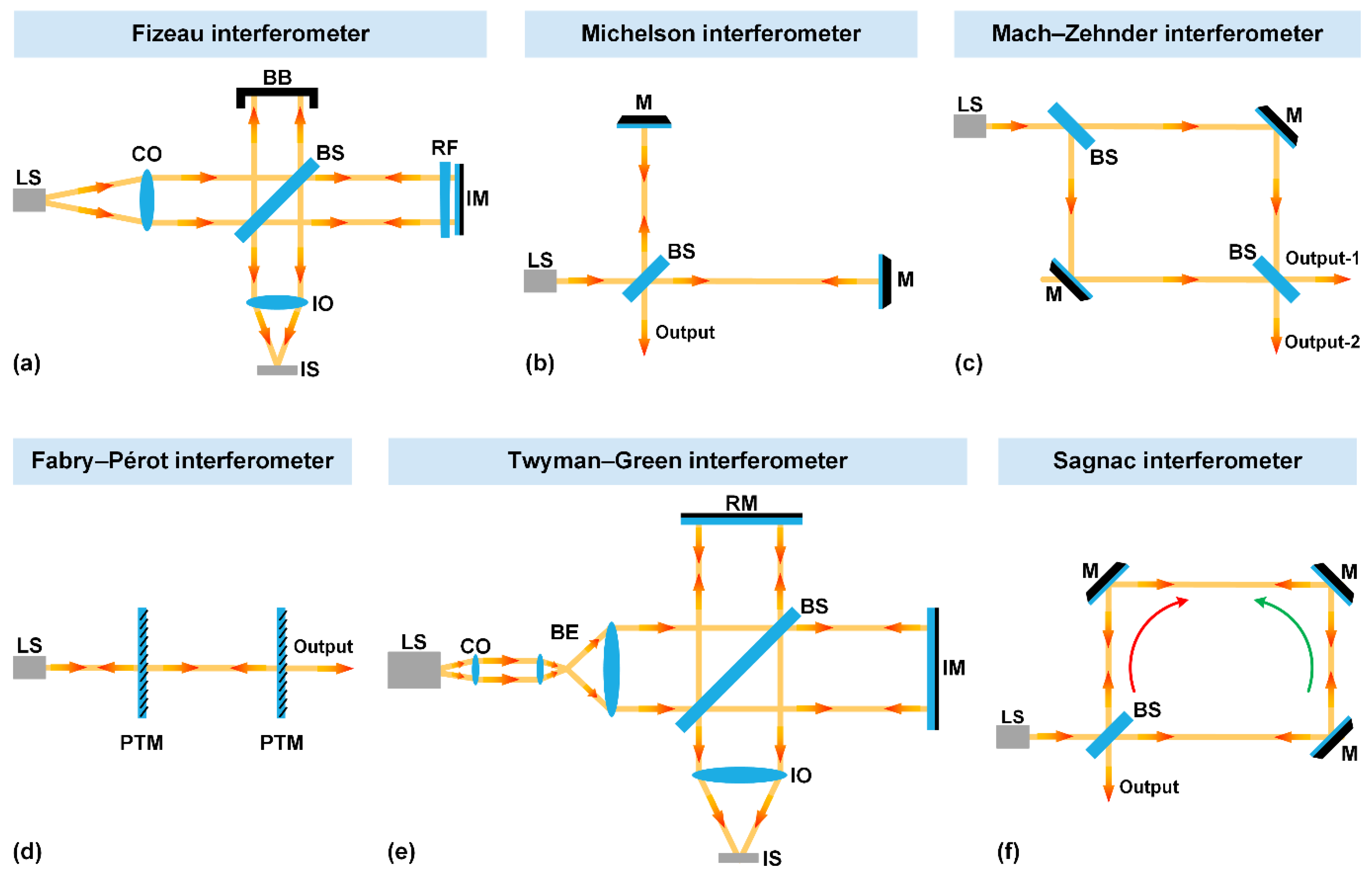
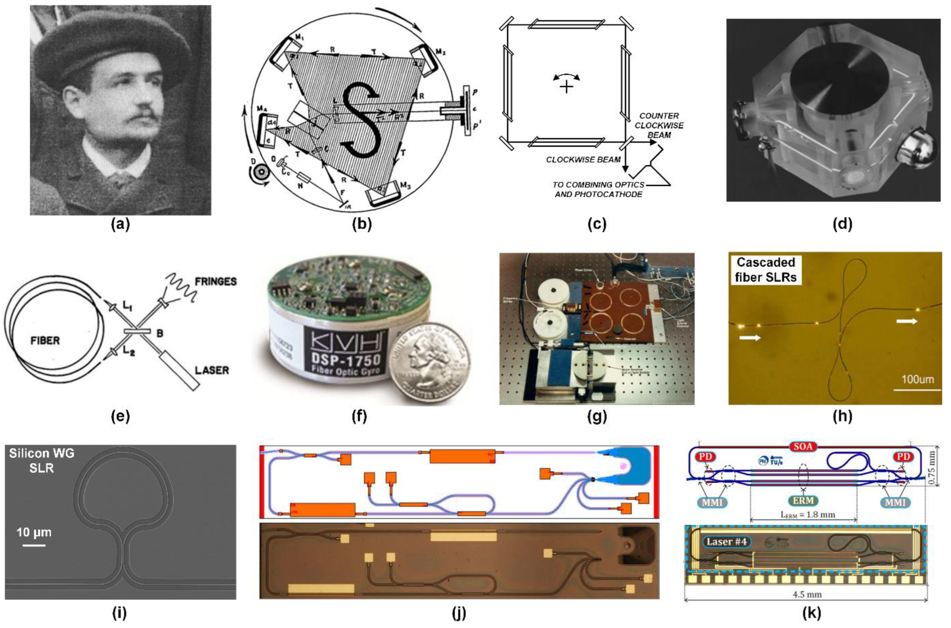
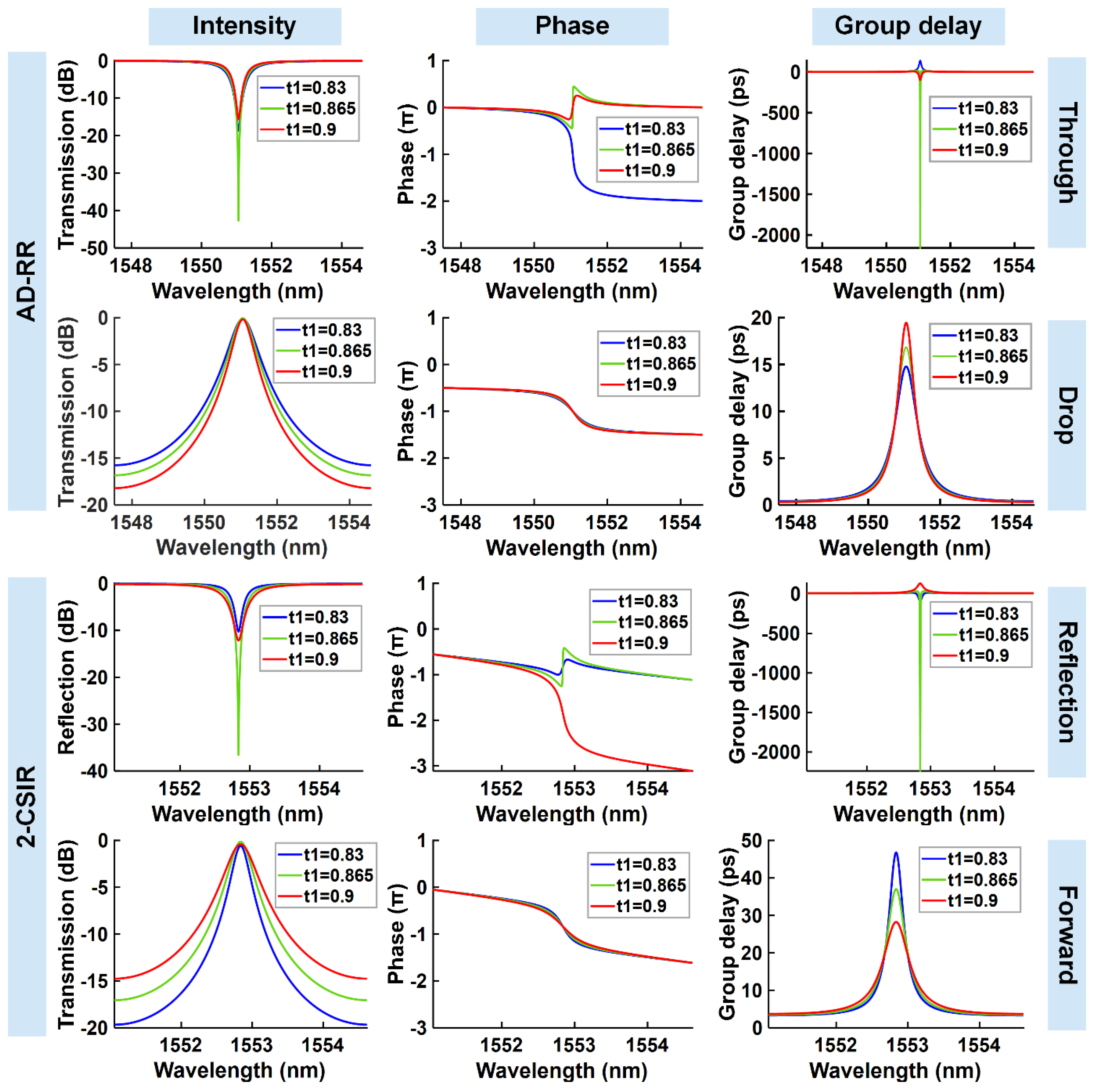
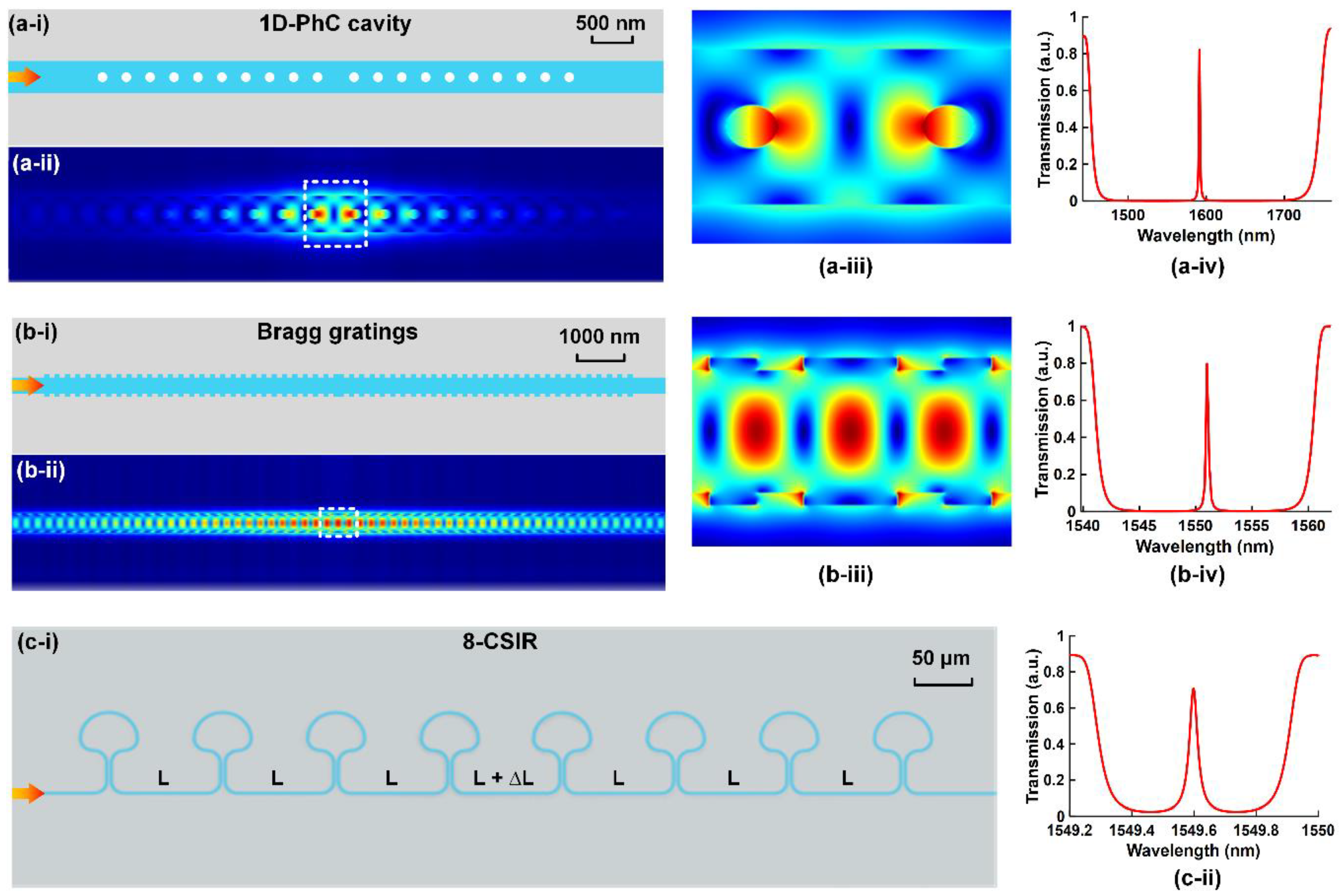
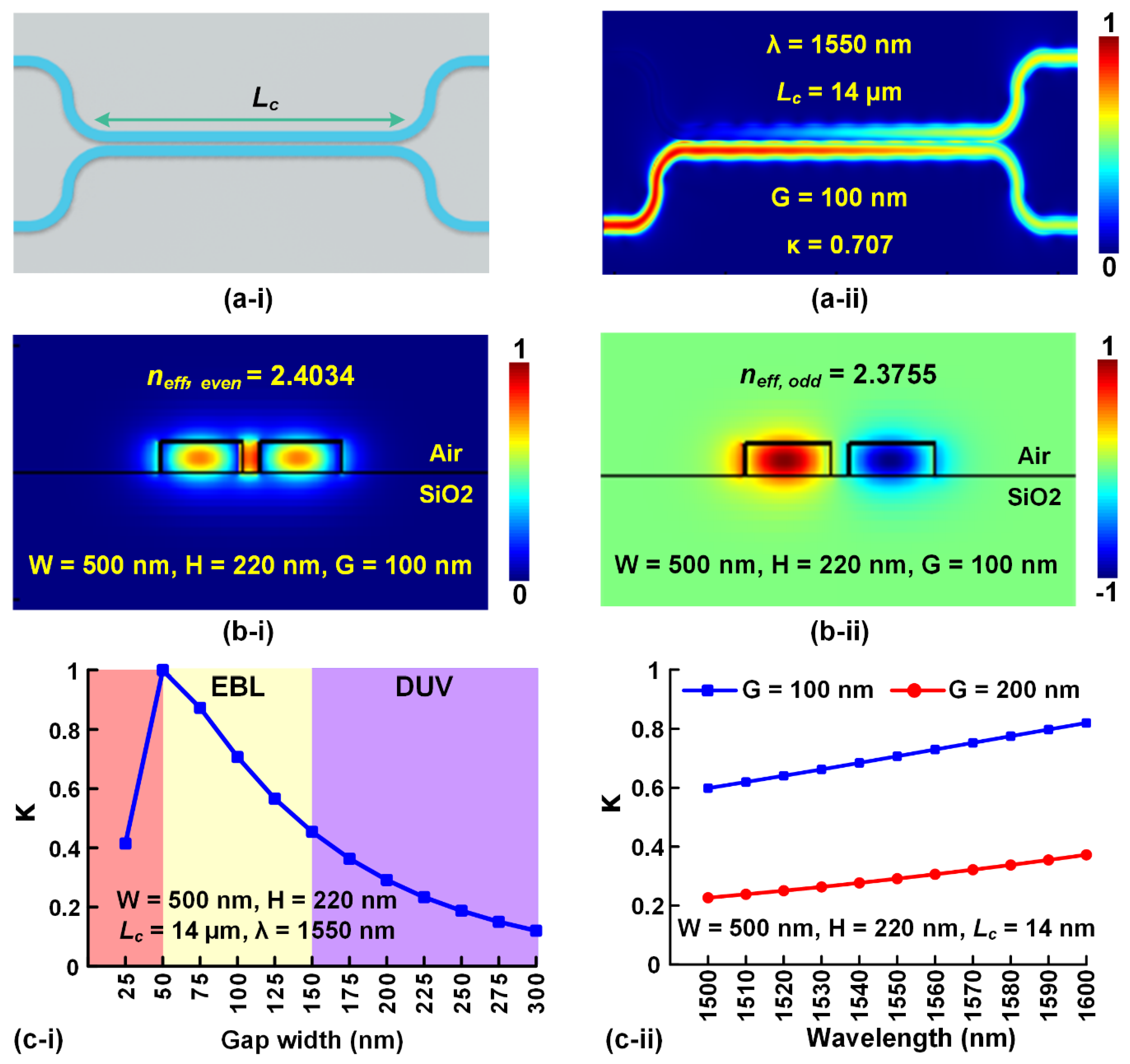
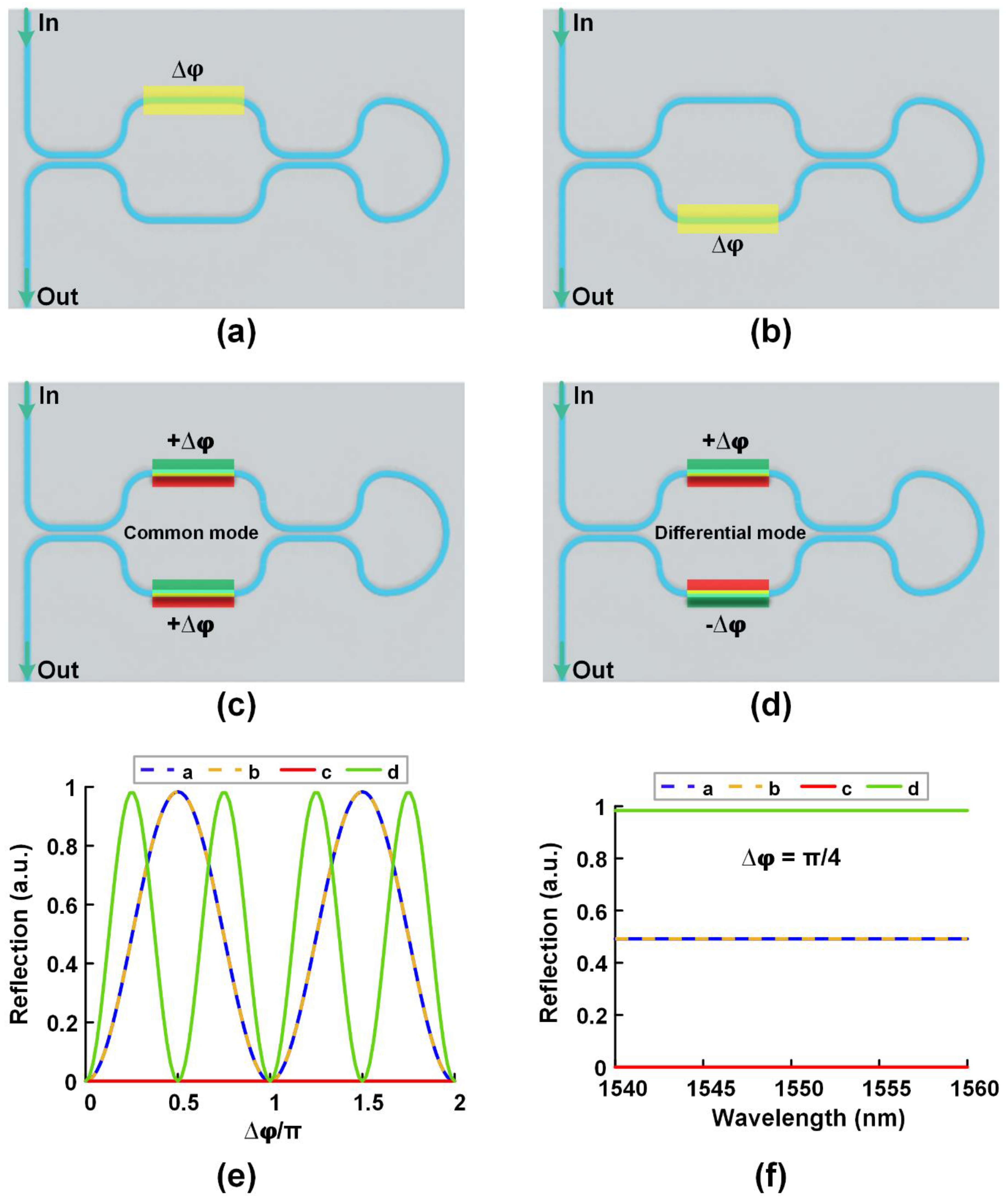
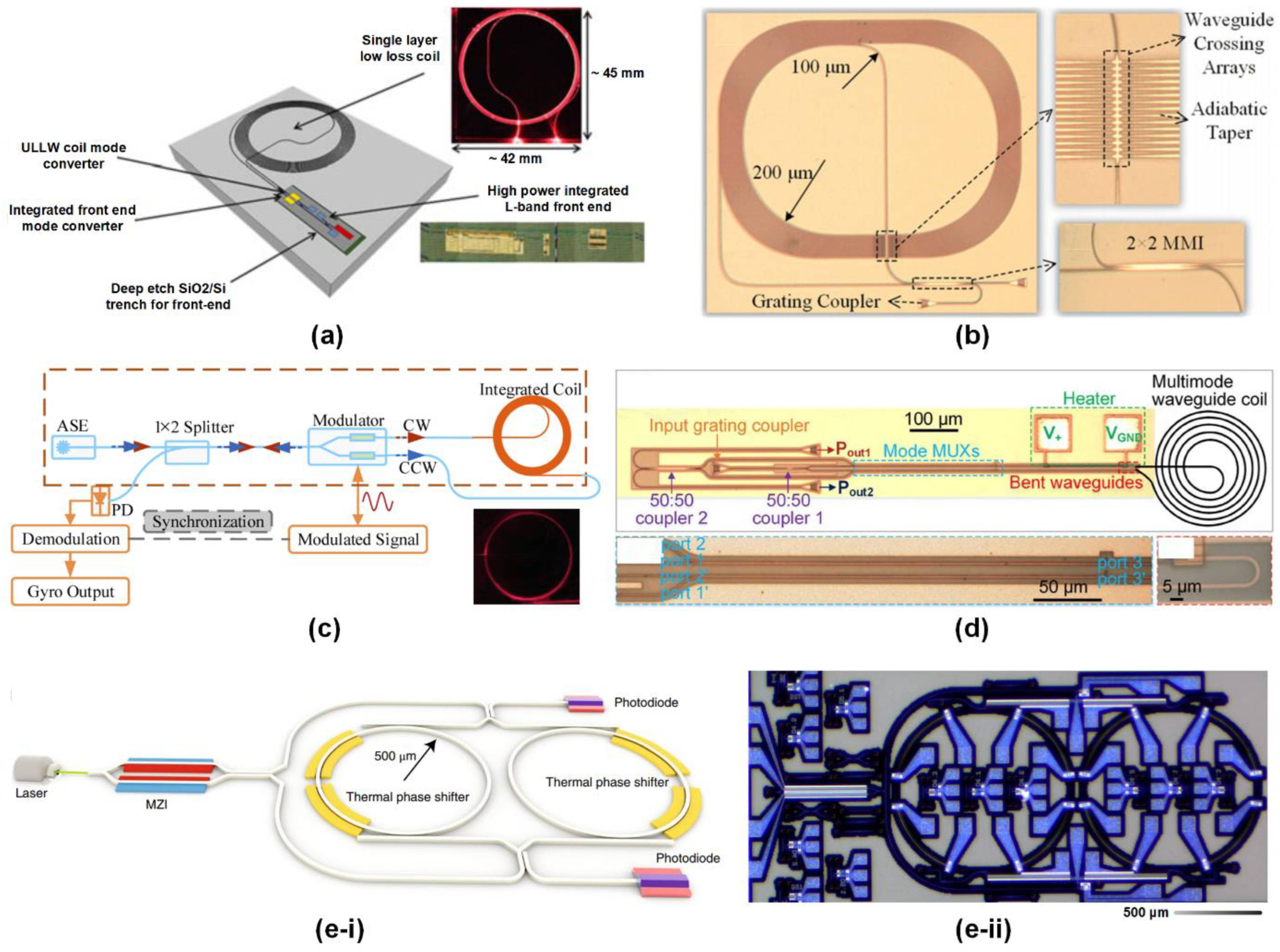
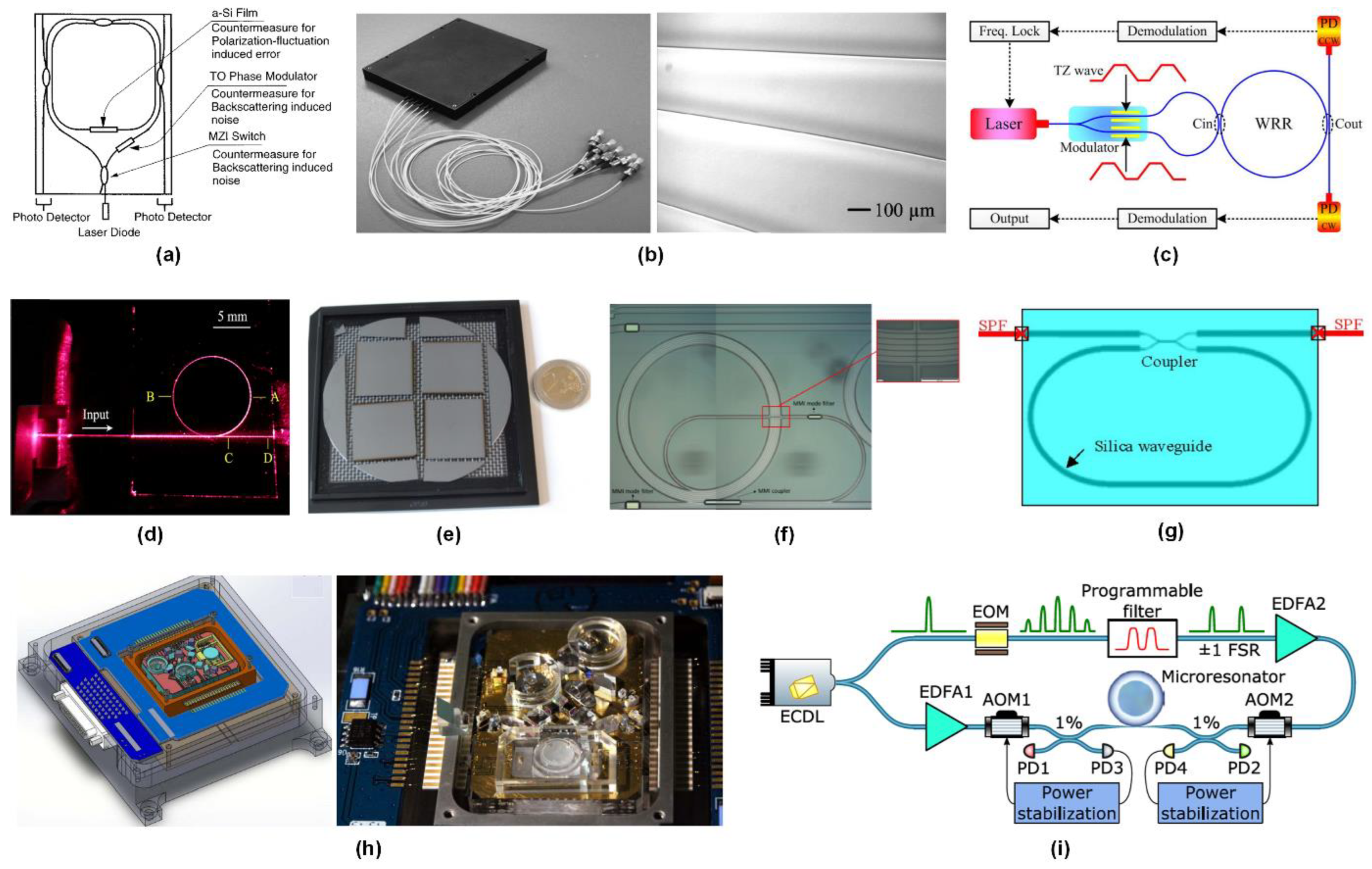
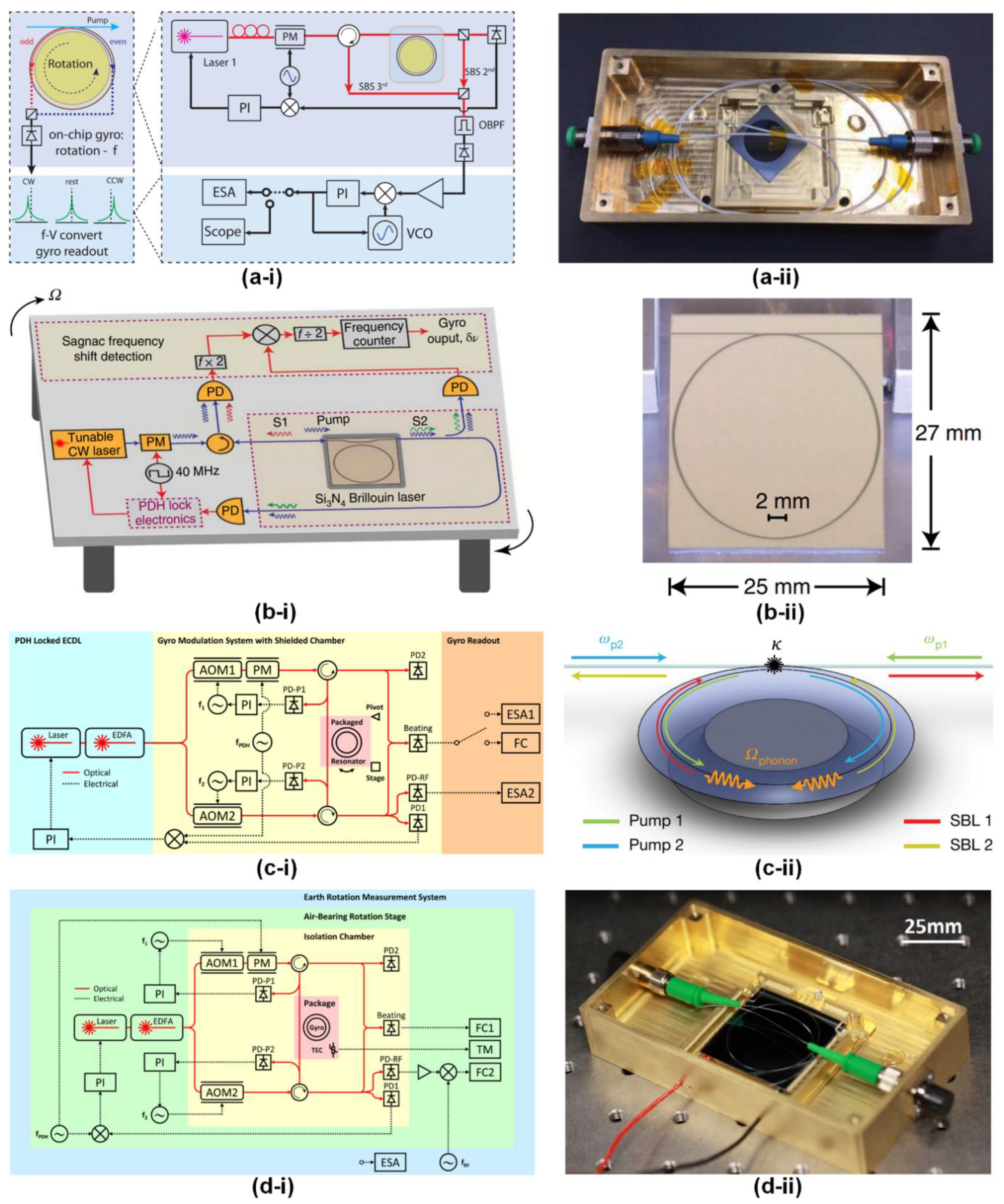
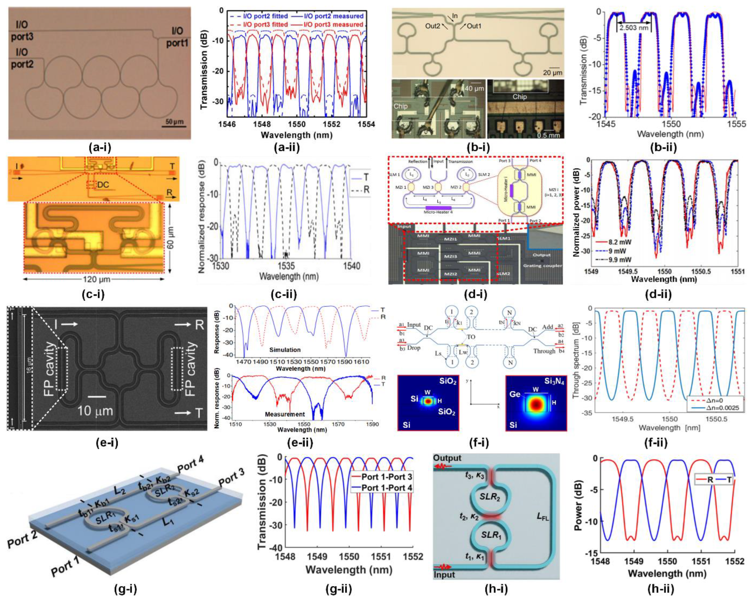
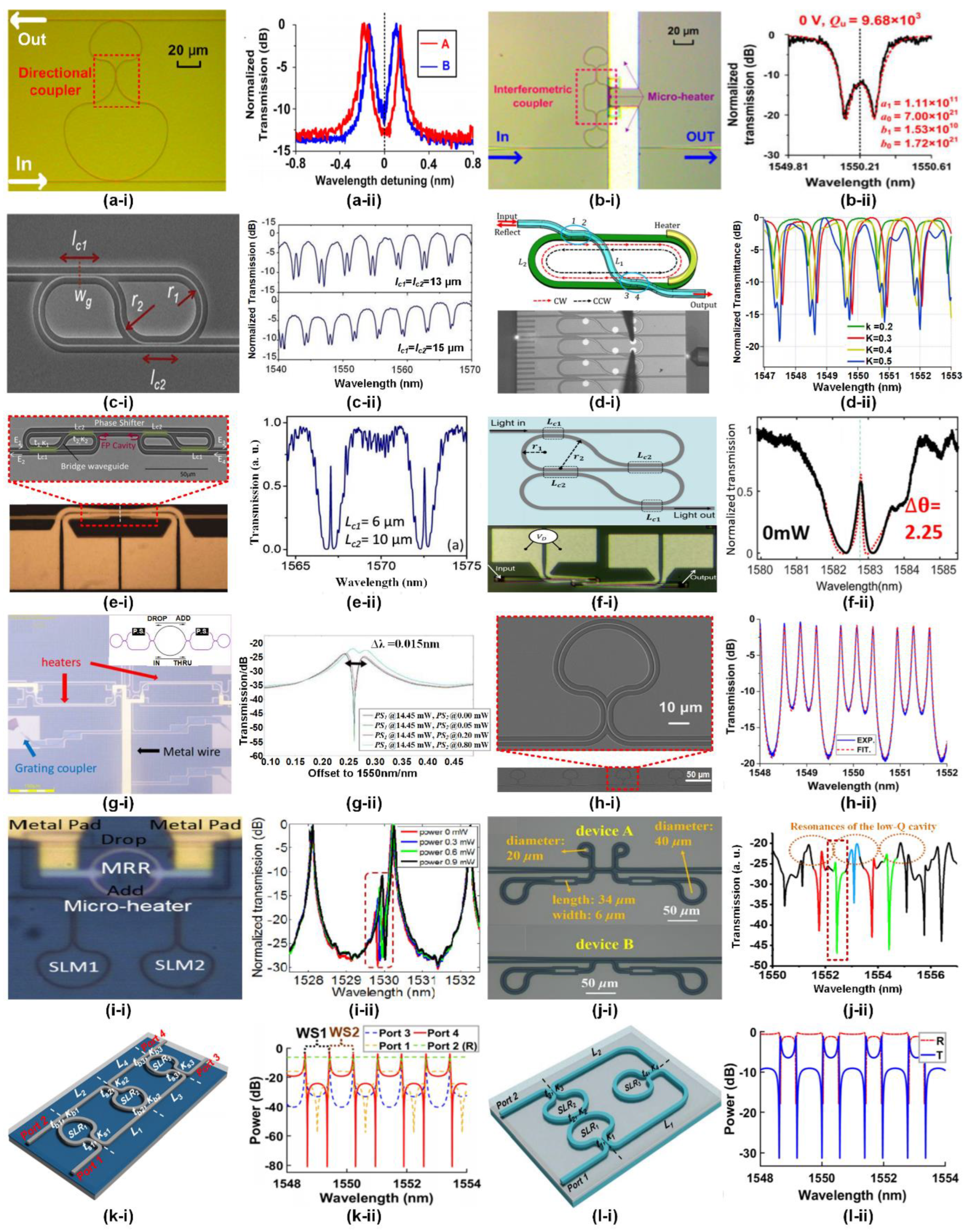
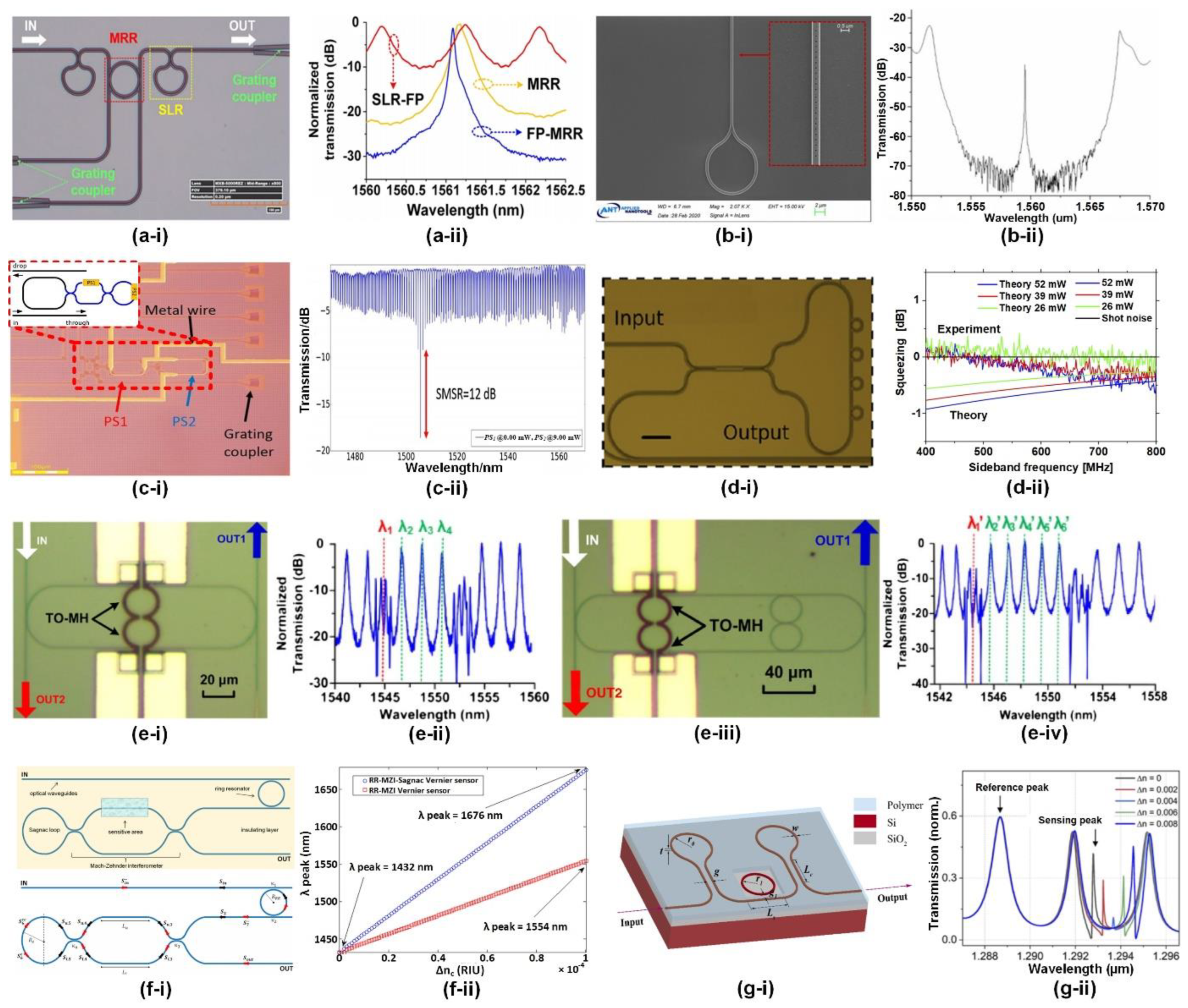
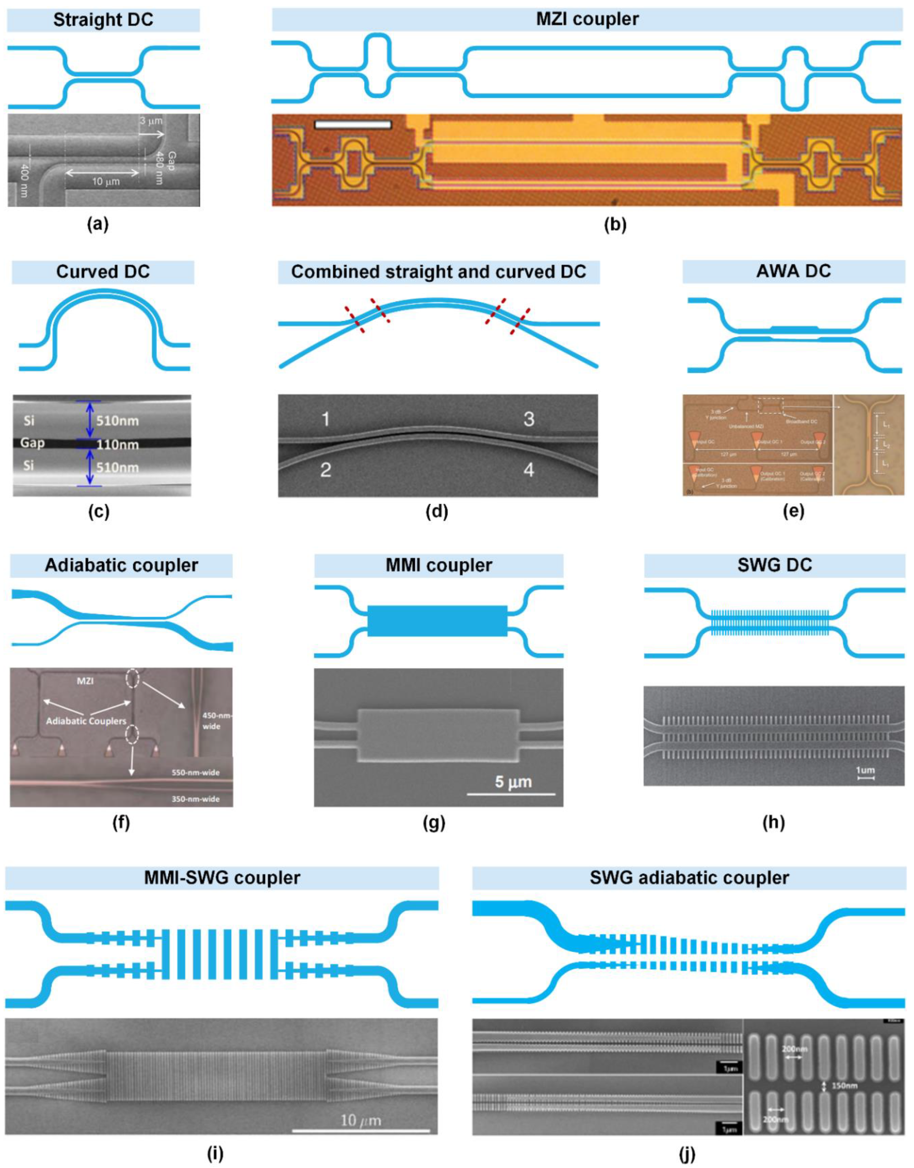
| Figure 7(a-i) | Connecting waveguides | Structural parameters |
Structure | Length | Transmission factor | Phase shift | |||||
| Bus waveguides (i = 1, 2) | Lwi | awi | φwi | ||||||||
| Sagnac loops (i = 1, 2) | Lsi | asi | φsi | ||||||||
| Scattering matrix equations a | Bus waveguides | Sagnac loops | |||||||||
|
|
|||||||||||
| Directional couplers (DCs) | Structural parameters |
Field transmission coefficient (i = 1 – 4) | ti | ||||||||
| Field cross-coupling coefficient (i = 1 – 4) | κi | ||||||||||
| Scattering matrix equations b | DC1 | DC2 | DC3 | DC4 | |||||||
| Input | Equations | ||||||||||
| Figure 7(b-i) | All units | Scattering matrix equations c | |||||||||
| Input | Equations | ||||||||||
| Type | Integrated components | Platform | Bias drift a) (deg/h) |
Sensitivity b) (deg/h) |
ARW c) (deg/h1/2) |
Ref. |
|---|---|---|---|---|---|---|
| IOG | Coiled waveguide | SiN | 58.7 | ‒ | 8.52 | [127] |
| IOG | Coiled waveguide | Si | ‒ | 184680 | ‒ | [128] |
| IOG | Coiled waveguide | Silica | 7.32 | ‒ | 1.26 | [129] |
| IOG | All the passive components and a thermo-optic micro-heater | Si | ‒ | 2304 | ‒ | [130] |
| IOG | A MZI switch, two RRs with thermo-optic micro-heaters, two germanium photodiodes, and several waveguide couplers | Si | 21600 | 432000 | 650 | [131] |
| PROG | RR | Silica | ‒ | ‒ | ‒ | [132] |
| PROG | RR | Silica | ‒ | ‒ | ‒ | [133] |
| PROG | RR | Silica | 324 | ‒ | ‒ | [134] |
| PROG | RR | Polymer | ‒ | 324 | ‒ | [135] |
| PROG | RR | InP | ‒ | 10 | ‒ | [136] |
| PROG | A spiral resonator coupled to a straight bus waveguide through a MMI coupler |
InP | 1 | 10 | ‒ | [137] |
| PROG | RR | Silica | 14.4 | 3.74 | ‒ | [138] |
| PROG | All parts are integrated on an optical micro-bench |
CaF2 | 3 | ‒ | 0.02 | [139] |
| PROG | Microrod resonator | Silica | ‒ | 7200 | ‒ | [140] |
| BRLG | Disk resonator | Silica | ‒ | 22 | ‒ | [141] |
| BRLG | RR | SiN | ‒ | 90000 | ‒ | [142] |
| BRLG | Wedge resonator | Silica | ‒ | ‒ | ‒ | [143] |
| BRLG | Wedge resonator | Silica | 3.6 | 5 | 0.068 | [144] |
| Device structure | Integrated platform | Corresponding atomic physics | Demonstration of dynamic tuning | Ref. |
|---|---|---|---|---|
| A close-loop resonator formed by 2 SIs connected via a directional coupler | SOI | ATS | No | [219] |
| A close-loop resonator formed by 2 SIs connected via a MZI coupler | SOI | ATS | Yes | [97,220] |
| 2 coupled SIs formed by a self-coupled optical waveguide | SOI | EIT | Yes | [221] |
| 2 coupled SIs formed by a bottom RR and a top S-bend waveguide | SiN | EIT | Yes | [222] |
| 2 cascaded self-coupled optical waveguides including 4 SIs | SOI | EIT | Yes | [223] |
| 4 coupled SIs | SOI | EIT | Yes | [224] |
| 2 cascaded SIs with MZI couplers embedded in a RR | SOI | EIT | Yes | [225] |
| 3, 4, and 8 cascaded SIs | SOI | Multiple energy level splitting |
No | [56] |
| An add-drop RR coupled to an FP cavity formed by cascaded SIs | SOI | Fano resonance | Yes | [226] |
| Two coupled FP cavities formed by cascaded SIs | SOI | Fano resonance | No | [227] |
| A zig-zag-like resonator formed by 3 coupled SIs | N/A a) | Fano resonance | N/A a) | [187] |
| 3 SIs formed by a self-coupled waveguide | N/A a) | Fano resonance | N/A a) | [188] |
Disclaimer/Publisher’s Note: The statements, opinions and data contained in all publications are solely those of the individual author(s) and contributor(s) and not of MDPI and/or the editor(s). MDPI and/or the editor(s) disclaim responsibility for any injury to people or property resulting from any ideas, methods, instructions or products referred to in the content. |
© 2023 by the authors. Licensee MDPI, Basel, Switzerland. This article is an open access article distributed under the terms and conditions of the Creative Commons Attribution (CC BY) license (http://creativecommons.org/licenses/by/4.0/).


