1. Introduction
According to the fact sheets from the World Health Organization, blood and vascular associated diseases (e.g., heart diseases, stroke, hypertensive disease, aneurysm) have become the top global factor of death, nearly 5% of the population in the United States have at least one cerebral aneurysm (CA) and about 0.2% result in stroke from rupture annually [
1,
2]. Both genetic and environmental factors can contribute to the initiation/growth of intracranial aneurysms, however; the impact of each factor is still ambiguous [
3]. Uniquely, hemodynamic roles in monozygotic twins (MTs) provide a scenario limiting the variability of genetic factors. Thus, it is desirable to reveal the underlying mechanisms associated with morphological alterations and hemodynamics differences affected by embryological and environmental factors utilizing MTs neurovascular systems for investigations.
There is an incomplete understanding of the importance of many measurable stressors on the cerebral vascular anatomy. Numerous studies have demonstrated the potentiality of low wall shear stress (WSS) leading to different tissue mechanical stabilities of the arterial wall, as well as regions of accelerating blood flow with high WSS and positive WSS spatial gradients leading to extracellular matrix degradation and cellular loss. Others have proposed arterial regions subjected to high WSS, but negative WSS spatial gradients, appear to be protected from matrix degradation [
4]. The expression of specific endothelial cell and smooth muscle cell phenotypes appears to depend not only on an interplay of local hemodynamic environmental factors, but also on intrinsic genetically programmed biology [
5,
6]. MTs reduce genetic variability (e.g., deoxyribonucleic acid (DNA)) and often share similar chronic health problems and habits. Arterial morphologies and associated blood flow patterns are affected by post-zygotic changes and epigenetic effects in utero which is not completely understood. The assumption of identical morphology and hemodynamics for MTs is questionable and needs further investigation.
To the best of our knowledge, there is no existing study to investigate the performances of hemodynamics such as WSS and oscillatory shear index (OSI) in the MTs. The only specific study [
7] compared the blood flow rates in the circle of Willis (CW) and CW morphology in sixty-four twins (i.e., 19 MTs and 13 dizygotic twins) using transcranial color-coded sonography. The difference of CW morphologies between twins were observed while the specific hemodynamic feature (e.g., OSI and WSS) were not investigated. Thus, to facilitate the understanding of morphology and hemodynamics in the MTs, and enrich the case studies in the CA research community, a careful study on the pathophysiology of CAs in MTs models is extremely valuable.
To quantify the differences in morphology and hemodynamics of cerebral arterial and aneurysmal models in a pair of MTs (i.e., twin A and twin B), the configurations and dimensions of the reconstructed models were compared first to identify differences related to embryological and environmental factors. Then, to quantify hemodynamic characteristics in the MTs, an
in-vitro validated computational fluid dynamics (CFD) CA model [
8] was employed to model the realistic blood flow patterns in the MTs. The findings provide a pathway to understand impacts of genetic and environmental factors on the morphology, which can further affect hemodynamics affiliated pathogenesis of neurovascular diseases. In addition, the study can also check the rationality of the assumption that simplifying the MTs to share identical cerebral arteries.
2. Comparisons in Morphology and Dimensions
2.1. Information and Symptoms of Patients
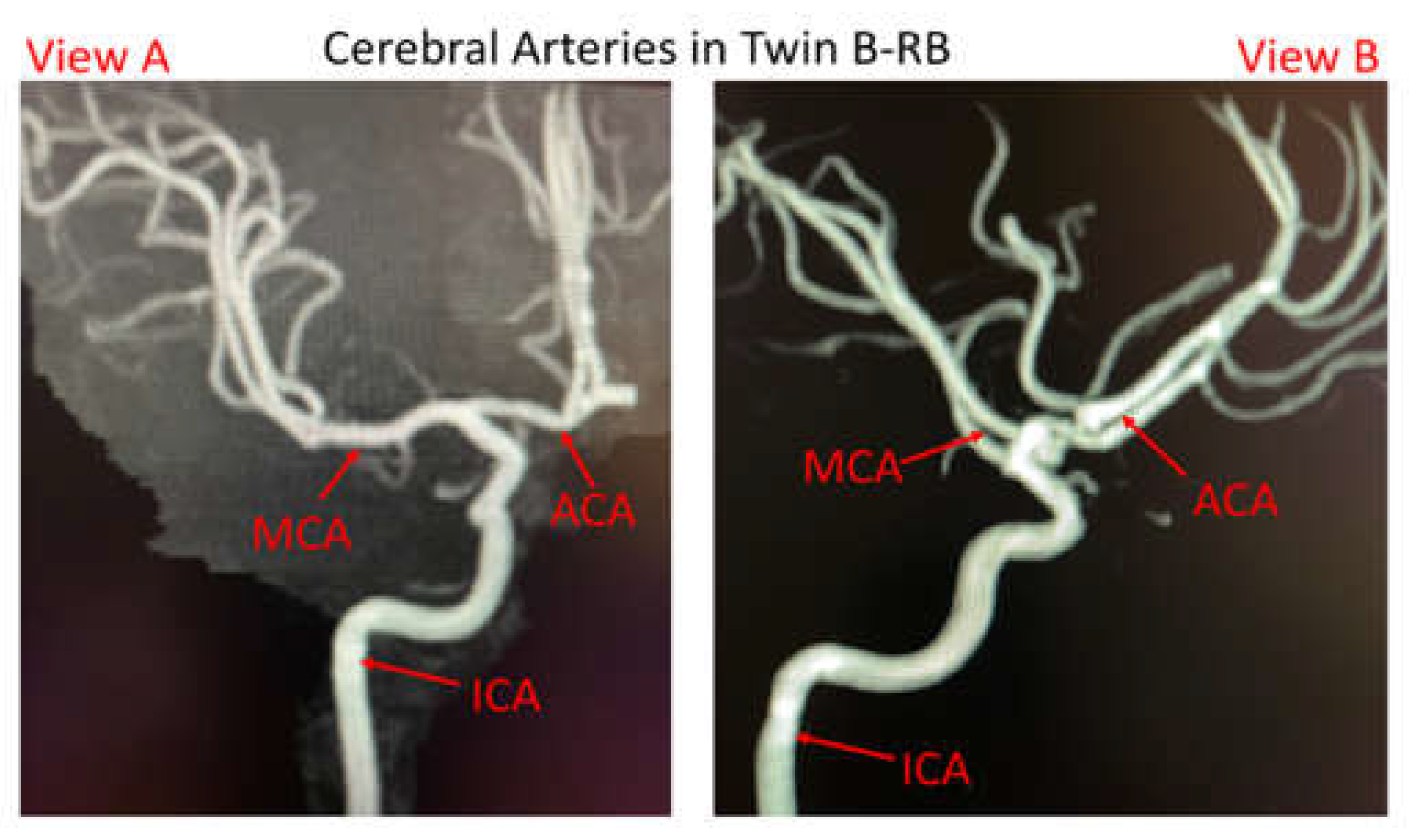
The pair of male MTs is 45~55 years old, with identical appearance and height, apart from the weights (twin A with 87.3 kg and twin B with 70.3 kg). Both twins had similar comorbidities (nearly identical smoking histories and essential hypertension profiles) according to the acquired information from a local hospital (Dayton, Ohio, USA). Twin A suffered a ruptured aneurysm located at the bifurcated region of anterior cerebral arteries (ACAs) in the right brain (RB), while he has no left ACA branches. Twin B has a small, unruptured bleb located at the left ACA bifurcation (LB). However, it should be mentioned that digital subtracted catheter information for twin B-RB is not available because no aneurysm was found in the right brain, but magnetic resonance imaging (MRI) of cerebral arteries showed twin B-RB has ACAs (see
Figure 1).
2.2. Reconstructed Arterial and Aneurysmal Models
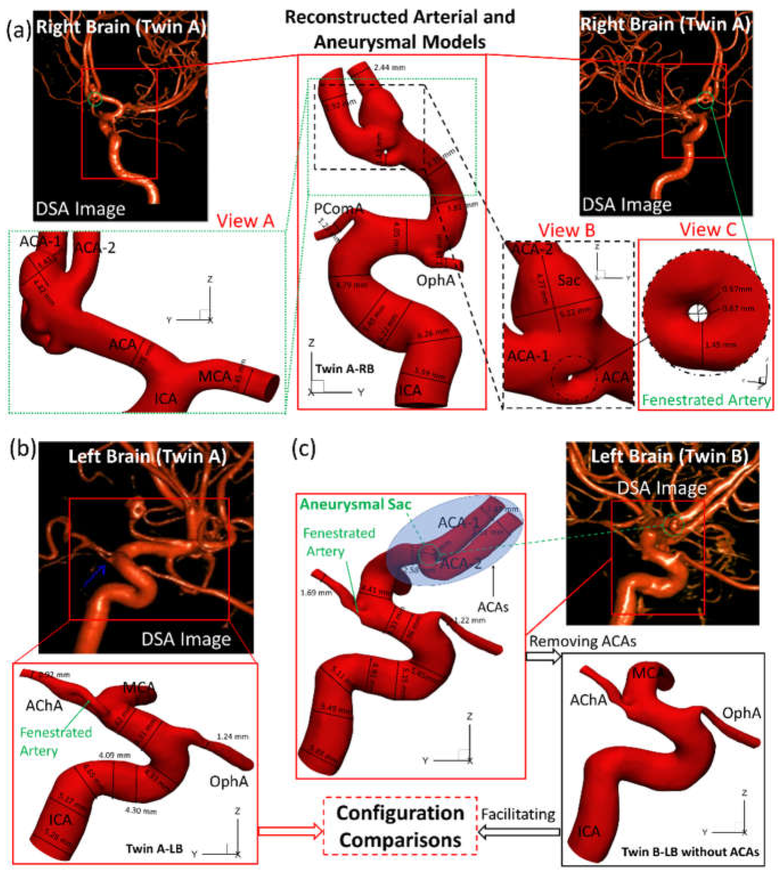
As shown in
Figure 2, the reconstructed models based on digital subtraction angiography (DSA) images, i.e., twin A-RB, twin A-LB, twin B-LB, and twin B-LB with ACA branches virtually removed (only for configuration comparison), were reconstructed using Mimics Research 23.0 (Materialise NV, Leuven, Belgium), based on 390 non-invasive digital subtraction angiography (DSA) images scanned by the Artis Zee system (Siemens Medical Solutions USA, Inc., PA, USA). To balance between arterial curvature and smoothness, reducing tolerance 0.03 with 5 iterations and smooth factor 0.4 with 10 iterations were adopted in the reconstruction. Reconstructed models were used for comparisons of morphologies and hemodynamics between the twins.
2.3. Dimensions and Configurations
Figure 2(a)&(b) manifest that the diameter of right internal carotid artery (ICA) of twin A is 10% larger than the counterpart in the LB, and RB has a fenestrated artery (FA) with an inner diameter ~0.6 mm with an aneurysmal sac (~5 mm) at the ACA bifurcation. Whether the FA contributed to the growth of the aneurysm is not clear and have been listed in the coming research plan. Both twin A and twin B have the same anterior choroidal artery branches (AChA) with a fenestration near its origin, but neither of them has a posterior communicating artery (PComA) (
Figure 2(a)&(c)). Unlike the configuration in twin A-RB, twin B-LB does not have a fenestration at the ACA bifurcation, however; there is a small unruptured aneurysmal bleb (~2 mm) associated with the left ACA bifurcation complex. More interestingly, twin A-LB does not have a left ACA which is completely different from twin B-LB, similar to a previous report [
7]. In addition, the arteries in twin B-LB are ~10% larger in diameter than that in twin A-LB, except the ophthalmic artery (OphA).
To match the extracted portion (ICA mainly) of the arterial model in twin A-LB and avoid the obscuring the MCA branches, the ACAs in twin B were removed (right corner of
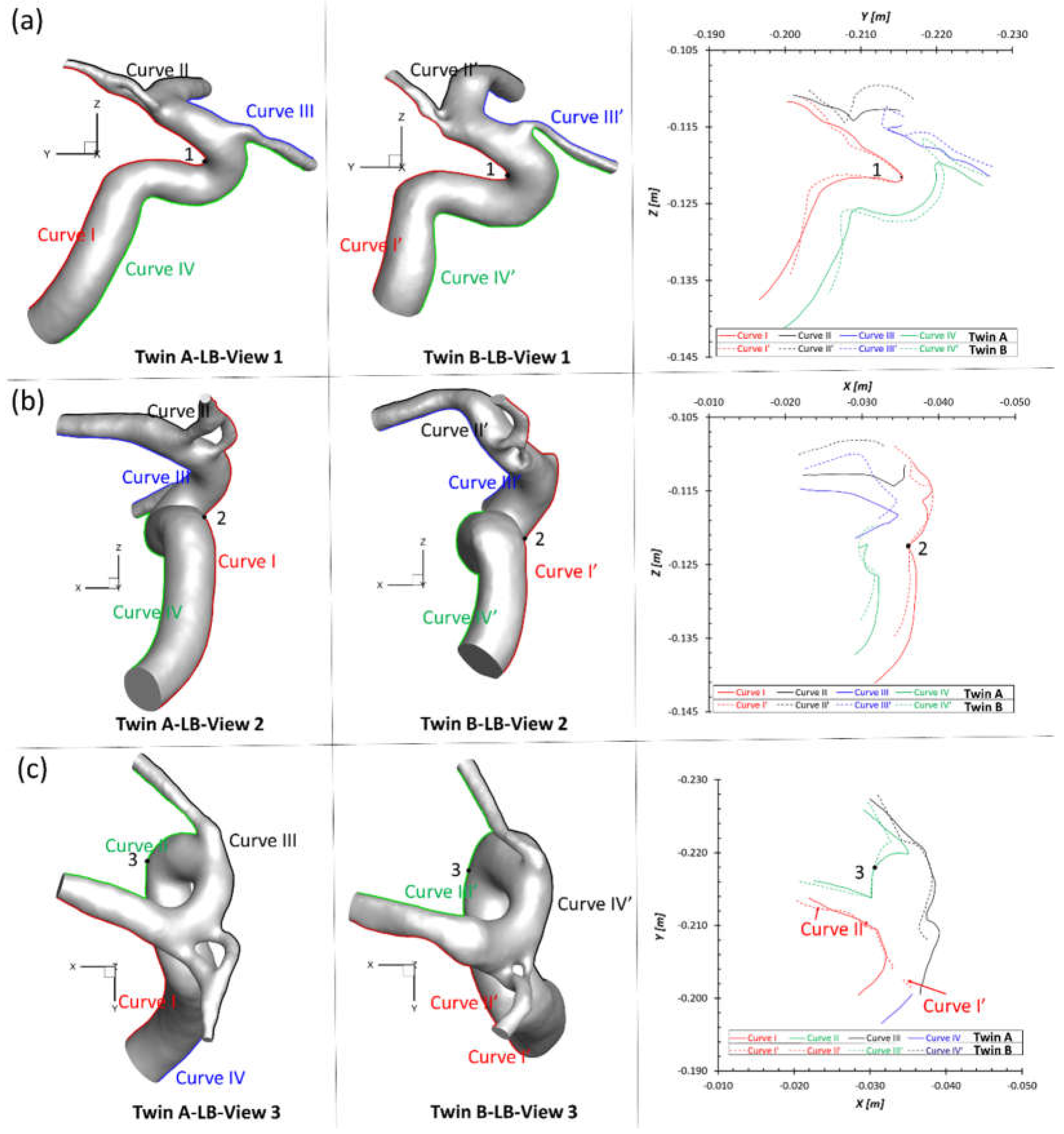
Figure 2(c)) purely for geometric comparisons. Three sets of projective images and outlines (see
Figure 3) of geometries from three perspective directions (YZ-plane, XZ-plane, XY-plane) were selected for comparisons, with corresponding benchmarked points, 1, 2, 3, respectively. Although twin A and twin B show an overall similar configuration, most dimensions and outlines show subtle differences from each other. Such discoveries can be explained by differing embryological influences during development for both MTs and less likely environmental factors. The dimensions and morphology of the neurovascular systems are not identical because of post-zygotic changes in DNA, and epigenetic effects that might influence overall gene expression. Therefore, the morphology in cardiovascular and neurovascular system can be significantly different due to environmental factors. How these variables affect hemodynamic characteristics between the twins is an interesting question, and were investigated in following sections.
3. Numerical Methods
3.1. Geometry and Mesh
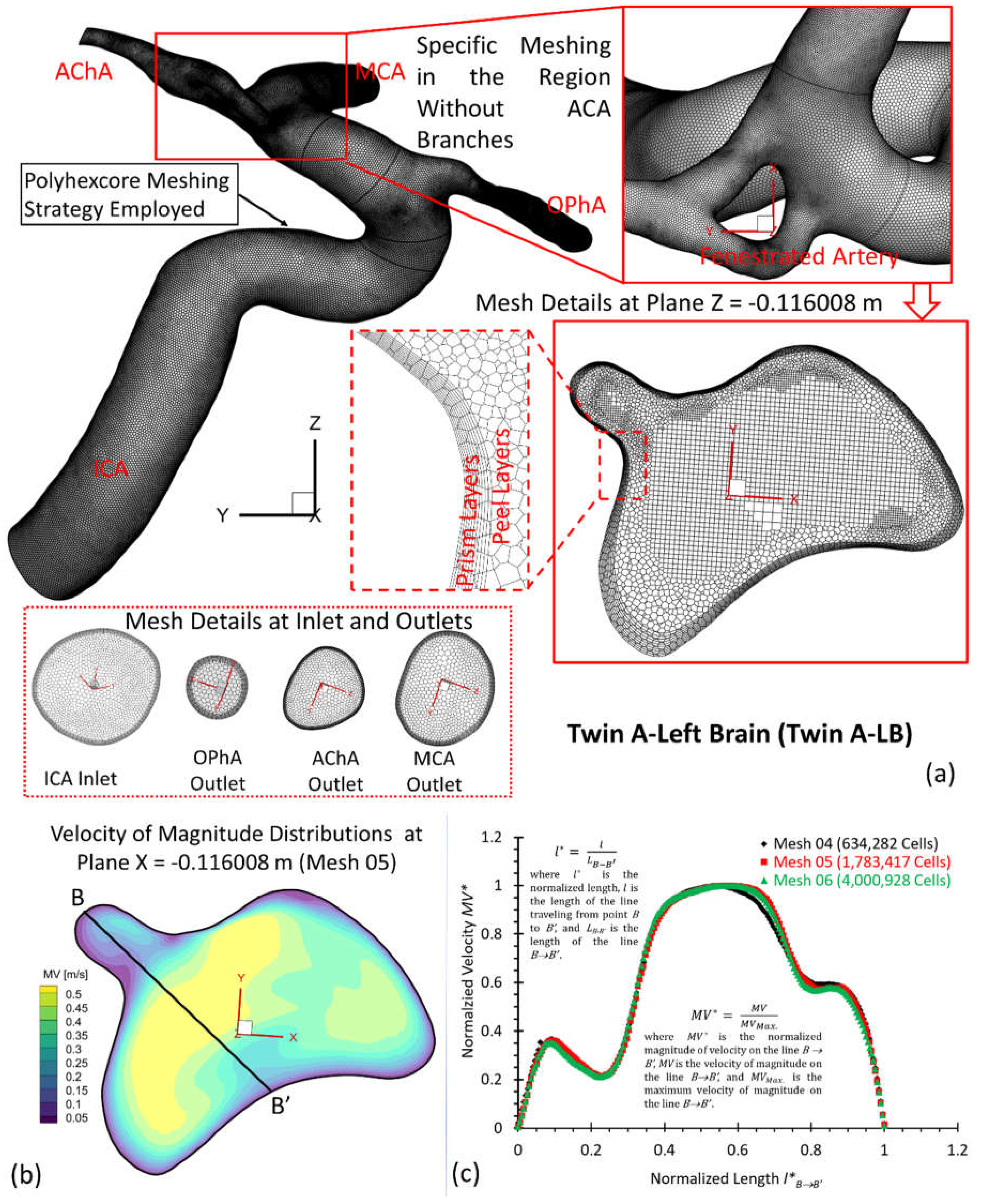
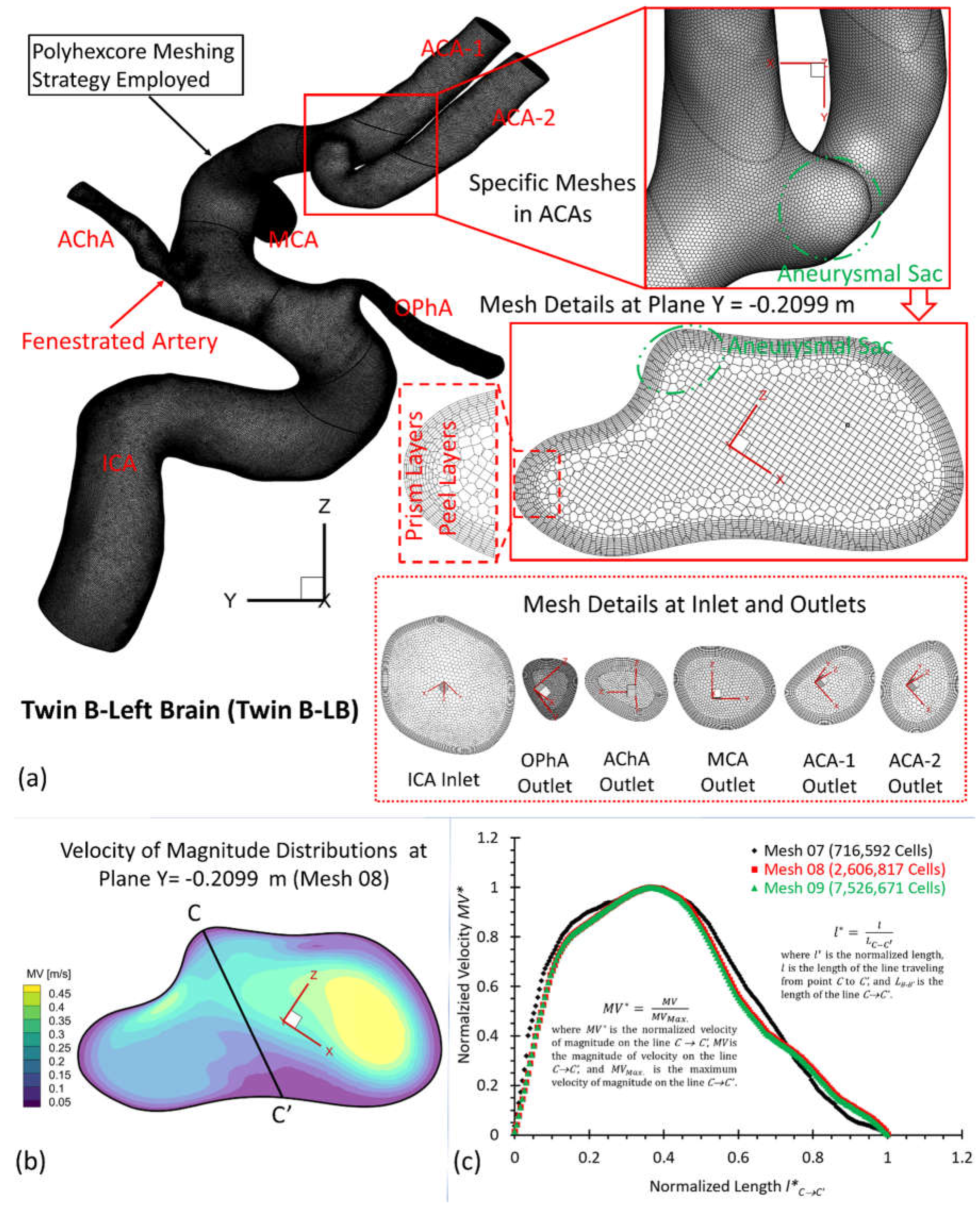
To investigate hemodynamic characteristics in the pair of MTs, e.g., twin A and twin B in this study, three arterial and aneurysmal models, e.g., twin A -LB and -RB, twin B-RB, were reconstructed using DSA images. Using ANSYS fluent meshing 2022 R2 (ANSYS Inc., Canonsburg, PA), total nine polyhexcore meshes (i.e., mesh 01, mesh 02, mesh 03, mesh 04, mesh 05, mesh 06, mesh 07, mesh 08, mesh 09) with different mesh sizes (see Table 1) were created for the mesh independence test, and meshing details have been visualized in
Figure 3(a),
Figure 4(a), and
Figure 5(a) for twin A-RB, twin A-LB, and twin B-LB, respectively. To determine the final mesh by considering the optimized balance between computational accuracy and efficiency, the mesh independence test has been performed by modeling the steady-state blood flow, using ANSYS fluent 2022 R2 (ANSYS Inc., Canonsburg, PA).
Specifically, regions (i.e., aneurysmal sac/bleb and arterial walls) with critical hemodynamic characteristics were discretized with refined mesh elements. Mesh independence tests were investigated by comparisons of non-dimensionalized velocity profiles
at selected locations (
Figure 4 (b)&(c)),
Figure 5 (b)&(c)), and
Figure 6 (b)&(c)), i.e., A-A’, B-B’, and C-C’ in the three investigated arterial models with in-model planes (i.e., plane X= 0.03007 m in twin A-RB, plane X = −0.116008 m in twin A-LB, and plane Y = − 0.2099 m in twin B-LB), respectively. A mean blood flow rate 265 ml/min [
9] in the ICA was employed to investigate the mesh sensitivity analysis in the three rebuilt models. In addition, blood properties, e.g., density of 1050 kg/m
3 and viscosity of
kg/m-s, were adopted for the mesh independence test.
Equations for normalized velocity
and normalized length, i.e.,
and
, can be expressed by:
where
is the maximum velocity magnitude along selected lines A-A’, B-B’, and C-C’ shown in
Figure 4(b),
Figure 5(b), and
Figure 6(b), respectively.
is the magnitude of velocity along selected lines from
,
, and
of cut-planes (i.e., plane X = 0.03007 m, plane X = −0.116008 m, and plane Y = −0.2099 m), respectively.
denotes the location of velocity vectors on lines A-A’, B-B’, and C-C’, respectively.
are lengths of lines A-A’, B-B’, and C-C’, respectively.
Using different meshes (see Table 1), the non-dimensionalized velocities are shown in
Figure 4(c),
Figure 5(c), and
Figure 6(c) for the corresponding models, e.g., twin A-RB, twin A-LB, twin B-LB, respectively. It can be observed that Mesh 01, Mesh 04, Mesh 07 are too coarse to obtain accurate results. The variations in simulated velocities are within 0.5% between Mesh 02 and Mesh 03. The similar results also can be found with the comparisons in Mesh 05 and Mesh 06, Mesh 08 and Mesh 09, respectively. Therefore, with 10 prism layers, 3 peel layers and a size growth ratio of 1.05 to capture accurate blood flow feature near arterial walls, the three final meshes (i.e., Mesh 02, Mesh 05, and Mesh 08) have 2,372,078, 1,783,417, and 2,606,817 cells for models of twin A-RB, twin A-LB, and twin B-LB to investigate the accurate hemodynamics, respectively.
3.2. Mathematical Equations
To explore hemodynamic patterns in MT models, our experimental validated non-Newtonian CFD CA model [
8] was employed to simulate the blood flow regime. The unsteady and periodic pulsatile incompressible blood flow can be modeled by the continuity and momentum equations, which are, i.e.,
where
is the blood velocity vector,
is the pressure,
is gravity vector, and
denotes blood density. In this study,
(i.e., 1050 kg/m
3) is adopted for the CFD simulations,
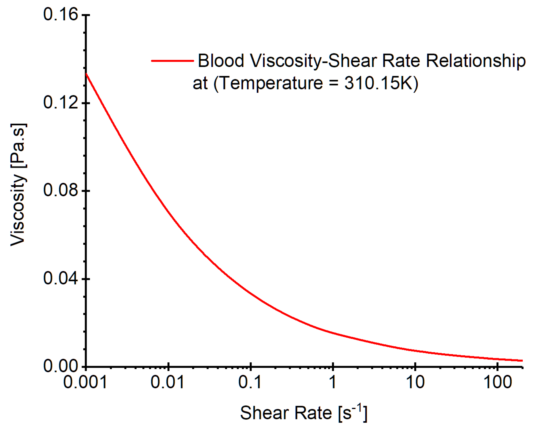
is blood viscosity determined by a non-Newtonian viscosity model at temperature 310.15 K (see
Figure 7) which was developed in our previous publication [
8]. Specifically, the model is expressed by, i.e.,
In Eqs. (5a)-(5c),
is the consistency index registered as 1.51
, and
is the power-law index defined as 0.685. In addition,
and
are minimum and maximum shear rates respectively. In the non-Newtonian blood flow modeling,
and
were registered as
-
and
-
[
10], respectively. The corresponding
and
can be determined by Eq. (5b). The shear rate
in the blood flow is computed by, e.g.,
Within the cardiac pulsatile blood flow regime, the flow in cerebral arterial system is featured as laminar-to-turbulence. Therefore, the shear stress transport (SST)
turbulence model [
11] was adapted for this study, predicting “laminar-to-turbulent” transition onset. In addition, to capture hemodynamic features more accurately in the near-wall regions with possible low Reynolds numbers, the low Reynolds correction was employed as well, which is a combination of SST
coupled with the correlation coefficient
and turbulent Reynolds number
additionally [
12]. The equations for turbulent viscosity, correlation coefficient and turbulent Reynolds number are [
12], e.g.,
In Eqs. (7)-(9),
is the turbulent viscosity,
is the turbulence kinetic energy,
is the specific dissipation rate,
is the correlation coefficient, and
is the turbulent Reynolds number. In addition, the hemodynamic parameters, such as time-averaged wall shear stress (TWSS), oscillatory shear index (OSI), time-averaged pressure (TAP), were defined in previous studies [
8,
13,
14].
3.3. Boundary Conditions
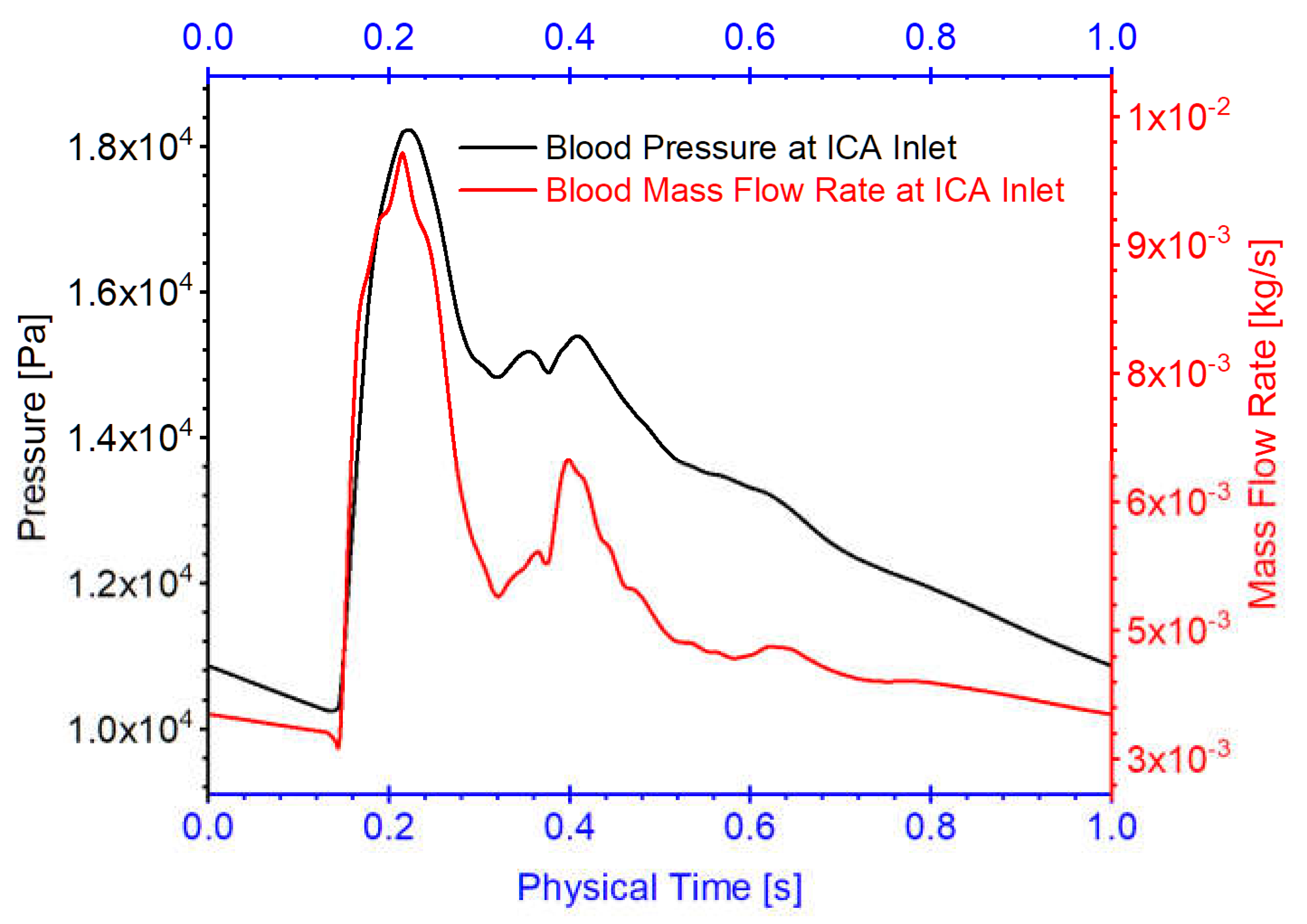
Three arterial models in twin A-RB, twin A-LB, and twin B-LB, were employed to investigate hemodynamics in the MTs. Specifically, one pulsatile flow rate waveform with a period of 1.0 s obtained from 1D model [
14,
15,
16] was applied as the boundary conditions at the ICA inlet in the simulations (see
Figure 8), mimicking cardiac pulsatile blood flow conditions. Pressure outlet was assumed as outlets (i.e., OphA, PComA, AChA, ACA) flow condition with the assumed gauge pressure of zero. Additionally, the arterial walls are set as stationary, non-slip, and no-penetration. The backflow direction at the outlets were determined based on the known flow direction in the cell layer adjacent to the outlets.
3.4. Numerical Setups
CFD modeling tasks were executed using Ansys fluent 2022 R2 (Ansys Inc., Canonsburg, PA) on a local HP Z840 workstation (Intel® Xeon® Processor E5-2687W v4 with dual processors, 24 cores, 48 threads, and 128 GB RAM). With the computational time step-size , it required ~71, ~54, and ~ 75 hours to finish the simulations for three physical pulsatile periods for three models, e.g., twin A-RB, twin A-LB, and twin B-LB, respectively. It worth mentioning that three pulsatile cycles were simulated to ensure the stability of numerical modeling. The simulation results based on the third pulsatile period (i.e., period = 1.0 s) were employed to analyze hemodynamic characteristics in the MT models. The pressure-implicit with splitting of operators (PISO) algorithm was employed for the pressure-velocity coupling, and the least-squares cell-based scheme was applied to calculate the cell gradient. The second order scheme was used for the pressure discretization. In addition, the second-order upwind scheme was employed for the discretization of momentum, turbulent kinetic energy, and the specific dissipation rate. Convergence is defined for continuity, momentum, and supplementary equations when residuals are lower than .
4. Hemodynamic Modeling Results and Discussion
4.1. Hemodynamics in Twin A-RB
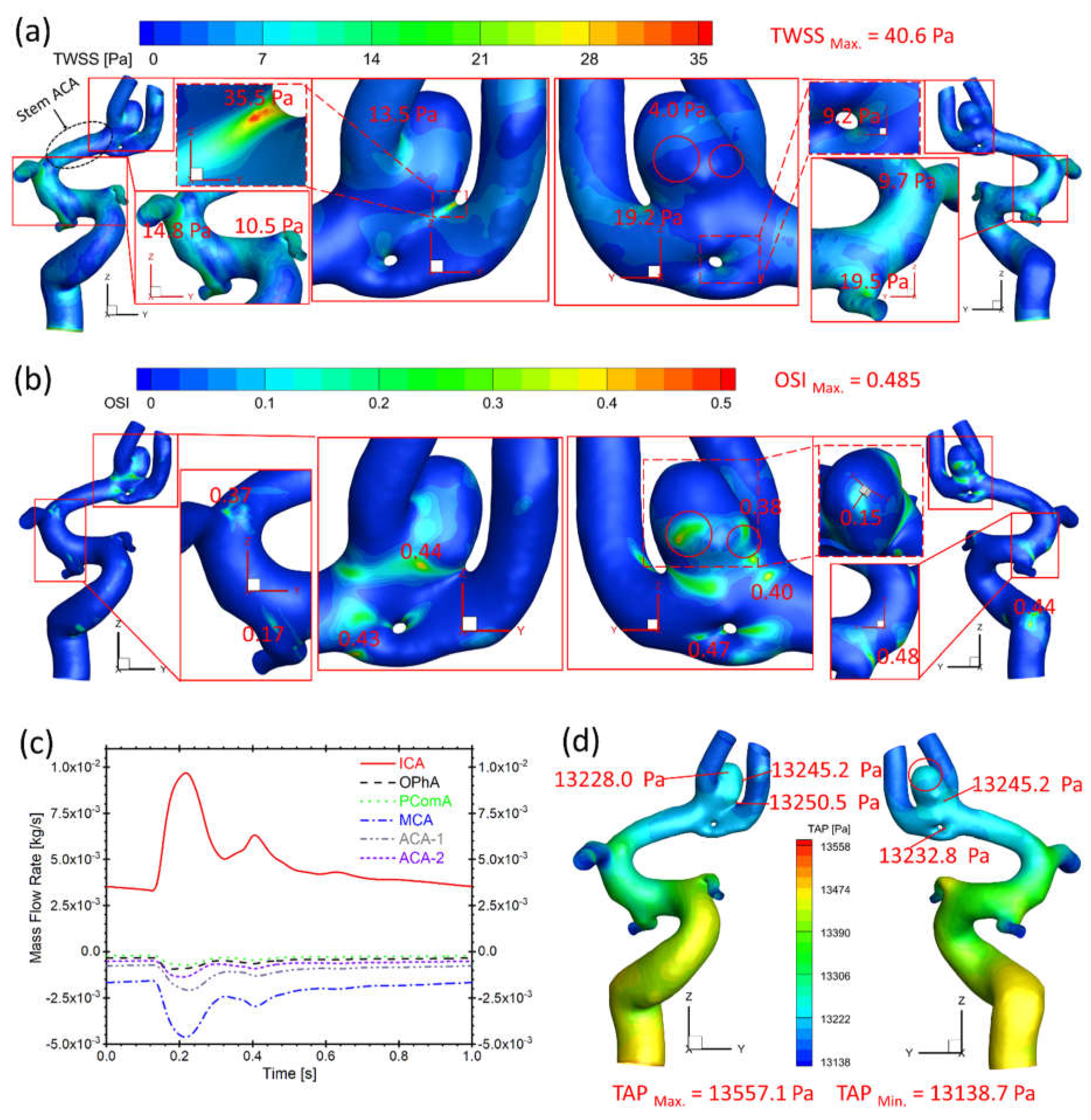
Figure 9(a) presents that the bifurcation region in twin A-RB registers relatively larger TWSS than other surrounding arteries, which is due to the direct impingement of the blood flow. This also could influence aneurysmal neck regions showing higher TWSS than other regions, reaching up to 35.5 Pa, in accordance with previous discoveries [
8].
Figure 9(b) manifests relatively high OSI distributions, which also appears on bifurcated regions and aneurysmal neck regions (close to 0.45) where flow diverts as the blood stream approaches such locations. In
Figure 9(a)&(b), the low TWSS and high OSI circumstance can be discovered in highlighted regions with red circles. Such luminal surfaces on the sac could suffer enlargement and then rupture with higher probability by hemodynamics-induced inflammatory-cell-mediated destructive remodeling [
17].
As for the blood flow rate in each artery (
Figure 9(c)), it has a close relationship with diameters of corresponding arteries. MCA has the largest diameter among bifurcation arteries which dominates ~50% of blood shunts from ICA, while PComA is the smallest artery which shunts the least blood flowrate (~5% of total flowrate). There is no significant difference in TAP distributions (~13,250 Pa) on the artery walls near ACAs comparing to the averaged pressure (13,158 Pa) of the ICA inlet (black waveform in
Figure 9(b)), the dynamic pressure contributes limited effects on the total blood pressure intrinsically, although TAP in the aneurysm (red circled region) is relatively higher than the surrounding regions due to the stagnation effect.
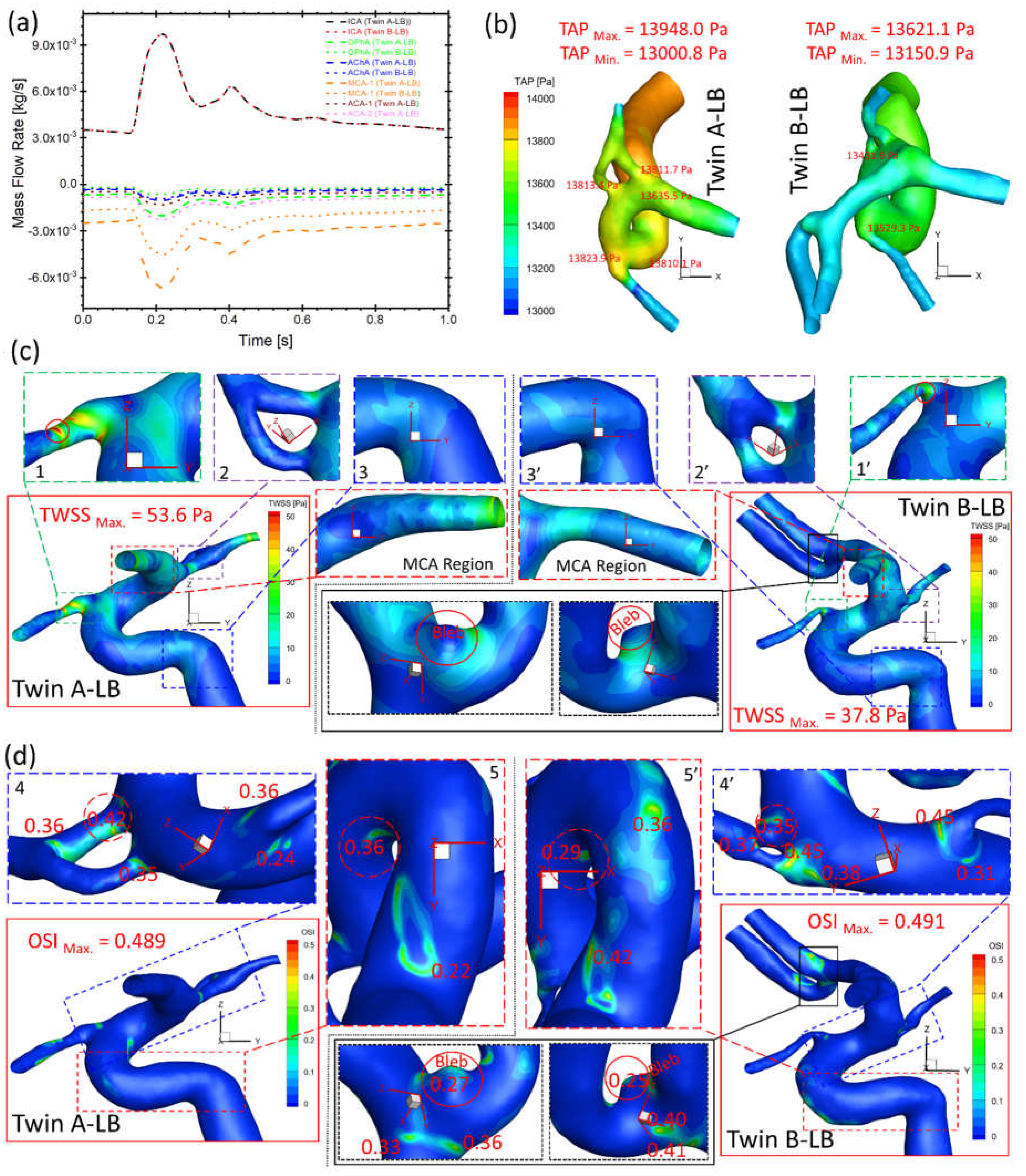
4.2. Hemodynamic Comparisons: Twin A-LB vs. Twin B-LB
Figure 10(a) presents the bifurcated artery with a larger diameter shunts more flows from ICA in both twin A-LB and twin B-LB arteries, similar to the case in twin A-RB (
Figure 9(c)). However, significant differences in shunts in corresponding arteries (i.e., OphA, AChA, and MCA) were observed in the twins (
Figure 10(a)), with discrepancies of volumetric blood flow rate in corresponding arteries between the MTs, from 16% (smallest) in AChA to 221% (largest) in the OphA, respectively. The blood flowrate in bifurcated twin A-MCA (without left ACAs) are much higher than the counterparts in twin B, because twin B-ACAs shunt over 30% flowrate from the ICA. This phenomenon can also explain the TAP loss in twin A being higher than the corresponding TAP loss in twin B (
Figure 10(b)), although differences in absolute values are insignificant. However, it is worth mentioning that the real flow conditions (flow rate and pressure) may be different from the current setup (assumed identical) since the ICA flow conditions may not be identical in the twins. While the patient-specific flow conditions were not available in the current study, the future plan is to employ Doppler ultrasound technique [
18] to measure the patient-specific blood flowrate in the ICA for follow-up examinations, to facilitate more accurate hemodynamic information through CFD modeling.
Under the identical ICA flow boundary condition, TWSS on most regions of twin A arterial wall is higher than the shear stress in twin B (
Figure 10(c)), similar to the observations of higher TAP distributions in twin A (
Figure 10(b)). The twins registered the highest TWSS on the same artery (i.e., OphA) with significant differences in specific locations and absolute values, e.g., 53.6 and 37.8 Pa (regions 1 and 1’ in
Figure 10(c)), respectively. The small difference of TWSS distributions can also be found in 2 and 2’, 3 and 3’ in
Figure 10(c), separately. Moreover, MCA regions presents completely different characteristics in TWSS distributions between twin A and twin B (
Figure 10(c)), in which, twin B shows higher TWSS in the entrance region than the distal end, while twin A shows the reversed distribution pattern. It is because the MCA diameter shrinks from the junction end (entrance) to the distal end in twin A, but slightly expands in twin B. This difference then influences the velocity gradient in the artery and finally results in different TWSS distributions. In contrast to TWSS comparisons, OSI values in twin A are generally smaller than counterparts in twin B on most regions except two highlighted regions in Fig. 5(d), while the registered highest OSI in twin A (0.489) and twin B (0.491) are similar. Similar to the TWSS comparisons, the twins present locations with relatively high OSI (regions 4 and 4’, 5 and 5’ in
Figure 10(d)) on the same artery, while specific locations and values are different. In summary, although the investigated MTs share the same genes, embryological factors (post-zygotic changes in the DNA and epigenetic effects that might influence overall gene expression) can significantly affect the morphological sizes and configurations, such as no ACAs in twin A-LB. Despite identical DNA, varying hemodynamic performances are noted on the arteries. Additionally, a small bleb in the bifurcated left ACAs of twin B-LB (highlighted in
Figure 10(c)&(d)) suffers low TWSS and relatively high OSI under the pulsatile cardiac flow conditions, thus surveillance should precede intervention, due to its small size but with considerable probability to enlarge and rupture.
5. Conclusions
Our findings contributed to the knowledge gap in CA pathobiology by studying the configurations and hemodynamics in identical twins. The morphological and hemodynamic comparisons led to key conclusions as follows, e.g.,
Although the twins share identical DNA, identical appearances and heights, the cerebral arterial morphological configuration and dimensions are different due to non-genetic factors.
Neck regions of the ruptured aneurysmal sac in twin A-RB present higher TWSS, and some local luminal surfaces on the sac may have higher probability to enlarge/rupture given the appearance of relatively high OSI and low TWSS. Such distribution was also observed in the small bleb in twin B-LB.
Differences in morphologies although sharing same DNA information further lead to varied hemodynamic characteristics in arteries, thus assuming the twins have identical arteries could mislead the hemodynamic analysis in the vascular system.
Author Contributions
Conceptualization, Z.Y. and B.L.; methodology, H.Y. and Z.Y.; software, H.Y. and Z.Y.; validation, H.Y. and Z.Y.; formal analysis, H.Y., Z.Y., and B.L.; investigation, H.Y. and Z.Y.; resources, Z.Y. and B.L.; data curation, H.Y., L.B, and Z.Y.; writing—original draft preparation, H.Y.; writing—review and editing, Z.Y., L.B., and B.L.; visualization, H.Y. and Z.Y.; supervision, Z.Y. and B.L.; project administration, Z.Y. and B.L.; funding acquisition, Z.Y. and B.L. All authors have read and agreed to the published version of the manuscript.
Funding
This research was funded by Premier Health and Boonshoft School of Medicine Endowment Funding at Wright State University.
Institutional Review Board Statement
The study was conducted in accordance with the Declaration of Helsinki, and approved by the Institutional Review Board (FWA#00002427) of Wright State University (protocol code IRB–2022–206 and date of approval on December 9, 2022) for studies involving humans.
Informed Consent Statement
Not applicable.
Data Availability Statement
Data available on request due to restrictions e.g., privacy or ethical.
Acknowledgments
The use of ANSYS software (Canonsburg, PA) as part of the ANSYS–WSU academic partnership agreement is gratefully acknowledged (Ms. C. Taylor and Mr. V. Ganore).
Conflicts of Interest
The authors declare no conflict of interest.
References
- Sadasivan, C.; Fiorella, D.J.; Woo, H.H.; Lieber, B.B. Physical Factors Effecting Cerebral Aneurysm Pathophysiology. Ann Biomed Eng 2013, 41, 1347–1365. [Google Scholar] [CrossRef] [PubMed]
- de Rooij, N.K.; Linn, F.H.H.; van der Plas, J.A.; Algra, A.; Rinkel, G.J.E. Incidence of subarachnoid haemorrhage: a systematic review with emphasis on region, age, gender and time trends. Journal of Neurology, Neurosurgery & Psychiatry 2007, 78, 1365–1372. [Google Scholar] [CrossRef]
- Sforza, D.M.; Putman, C.M.; Cebral, J.R. Hemodynamics of Cerebral Aneurysms. Annual Review of Fluid Mechanics 2009, 41, 91–107. [Google Scholar] [CrossRef] [PubMed]
- Meng, H.; Wang, Z.; Hoi, Y.; Gao, L.; Metaxa, E.; Swartz, D.D.; Kolega, J. Complex hemodynamics at the apex of an arterial bifurcation induces vascular remodeling resembling cerebral aneurysm initiation. Stroke 2007, 38, 1924–1931. [Google Scholar] [CrossRef] [PubMed]
- Nerem, R.M. Hemodynamics and the Vascular Endothelium. Journal of Biomechanical Engineering 1993, 115, 510–514. [Google Scholar] [CrossRef] [PubMed]
- Lehoux, S.; Tedgui, A. Cellular mechanics and gene expression in blood vessels. Journal of Biomechanics 2003, 36, 631–643. [Google Scholar] [CrossRef] [PubMed]
- Forgó, B.; Tárnoki, Á.D.; Tárnoki, D.L.; Littvay, L.; Fagnani, C.; Stazi, M.A.; Meneghetti, G.; Medda, E.; Farina, F.; Baracchini, C. Investigation of circle of Willis variants and hemodynamic parameters in twins using transcranial color-coded Doppler sonography. The International Journal of Cardiovascular Imaging 2018, 34, 1419–1427. [Google Scholar] [CrossRef] [PubMed]
- Yi, H.; Yang, Z.; Johnson, M.; Bramlage, L.; Ludwig, B. Hemodynamic characteristics in a cerebral aneurysm model using non-Newtonian blood analogues. Physics of Fluids 2022, 34, 103101. [Google Scholar] [CrossRef] [PubMed]
- Schöning, M.; Walter, J.; Scheel, P. Estimation of cerebral blood flow through color duplex sonography of the carotid and vertebral arteries in healthy adults. Stroke 1994, 25, 17–22. [Google Scholar] [CrossRef] [PubMed]
- Skalak, R.; Keller, S.R.; Secomb, T.W. Mechanics of blood flow. J Biomech Eng 1981, 103, 102–115. [Google Scholar] [CrossRef] [PubMed]
- Menter, F.R. Two-equation eddy-viscosity turbulence models for engineering applications. AIAA Journal 1994, 32, 1598–1605. [Google Scholar] [CrossRef]
- Wilcox, D.C. Simulation of Transition with a Two-Equation Turbulence Model. AIAA Journal 1994, 32, 247–255. [Google Scholar] [CrossRef]
- Yi, H.; Yang, Z.; Johnson, M.; Bramlage, L.; Ludwig, B. Experimental and Numerical Investigations on Hemodynamic Characteristics in an Internal Cerebral Artery Sidewall Aneurysm Model using Non-Newtonian Blood Analogue Fluids. Bulletin of the American Physical Society 2022. [Google Scholar]
- Yi, H.; Johnson, M.; Bramlage, L.C.; Ludwig, B.; Yang, Z. Effects of Pulsatile Flow Rate and Shunt Ratio in Bifurcated Distal Arteries on Hemodynamic Characteristics Involved in Two Patient-Specific Internal Carotid Artery Sidewall Aneurysms: A Numerical Study. Bioengineering 2022, 9, 326. [Google Scholar] [CrossRef] [PubMed]
- Yu, H.; Huang, G.P.; Yang, Z.; Ludwig, B.R. A multiscale computational modeling for cerebral blood flow with aneurysms and/or stenoses. International Journal for Numerical Methods in Biomedical Engineering 2018, 34, e3127. [Google Scholar] [CrossRef]
- Yu, H.; Huang, G.P.; Yang, Z.; Ludwig, B.R. Numerical studies of hemodynamic alterations in pre- and post-stenting cerebral aneurysms using a multiscale modeling. International Journal for Numerical Methods in Biomedical Engineering 2019, 35, e3256. [Google Scholar] [CrossRef]
- Meng, H.; Tutino, V.M.; Xiang, J.; Siddiqui, A. High WSS or Low WSS? Complex Interactions of Hemodynamics with Intracranial Aneurysm Initiation, Growth, and Rupture: Toward a Unifying Hypothesis. American Journal of Neuroradiology 2014, 35, 1254–1262. [Google Scholar] [CrossRef] [PubMed]
- Likittanasombut, P.; Reynolds, P.; Meads, D.; Tegeler, C. Volume flow rate of common carotid artery measured by Doppler method and Color Velocity Imaging Quantification (CVI-Q). J Neuroimaging 2006, 16, 34–38. [Google Scholar] [CrossRef] [PubMed]
Figure 1.
Cerebral artery system in twin B-RB based on collected magnetic resonance imaging (MRI) images (i.e., view A and view B).
Figure 1.
Cerebral artery system in twin B-RB based on collected magnetic resonance imaging (MRI) images (i.e., view A and view B).
Figure 2.
Morphologies and dimensions of cerebral arterial and aneurysmal models in the investigated genetic male twins. (a) Graphs show the specific arterial configurations and dimensions in twin A-RB, with an aneurysmal sac (~5 mm) (view B) and fenestrated arteries (view C); (b) Graphs present the dimensions and configuration of the arterial model which has ACAs in twin A-RB; (c) Graphs show the complete arterial and aneurysmal geometries with a small aneurysm bled located at the ACA bifurcation (left of
Figure 2(c)) in twin B-LB, and an arterial model (i.e., right of
Figure 2(c)) with ACAs virtually removed based on the left complete model to facilitate the configuration comparisons in the LB between the twins.
Figure 3.
Comparison of projective graphs and outline curves of partial LB arteries in the MTs in the Cartesian coordinate system. (a) Left two projective graphs show the projective images on the YZ-plane, and corresponding outline curves (right) show the lineaments of LB arteries in twin A and twin B with the overlapped benchmark point 1 (apex of the curvature); (b) Left two projective graphs show the projective images on the XZ-plane, and corresponding outline curves (right) show the lineaments of LB arteries in twin A and twin B with the overlapped benchmark point 2; (c) Left two projective graphs show the projective images on the XY-plane, and corresponding outline curves (right) show the lineaments of LB arteries in twin A and twin B with the overlapped benchmark point 3.
Figure 4.
Geometry and mesh details for twin A-RB model. (a) Detailed polyhexcore meshes for arterial and aneurysmal models, and specific meshing at selected plane, inlet and outlets; (b) Velocity distribution contours at plane X = 0.03007 m in Mesh 02; (c) Mesh independence test by comparing non-dimensionalized velocity profiles at line A-A’ among the mesh 01, mesh 02 (final), and mesh 03).
Figure 5.
Geometry and mesh details for twin A-LB model. a: Detailed polyhexcore meshes for the arterial model, and specific meshing at selected plane, inlet and outlets; b: Velocity distribution contours at plane X = - 0.116008 m in Mesh 05; c: Mesh independence test by comparing the non-dimensionalized velocity profiles at line B-B’ among the mesh 04, mesh 05 (final), and mesh 06.
Figure 6.
Geometry and mesh details for twin B-LB model. (a) Detailed polyhexcore meshes for the arterial and aneurysmal models, and specific meshing at selected plane, inlet and outlets; (b) Velocity distribution contours at plane X = - 0.2099 m in Mesh 08; (c) Mesh independence test by comparing the non-dimensionalized velocity profiles at line C-C’ among the mesh 07, mesh 08 (final), and mesh 09.
Figure 7.
Realistic non-Newtonian blood viscosity profiles employed in the CFD modeling.
Figure 7.
Realistic non-Newtonian blood viscosity profiles employed in the CFD modeling.
Figure 8.
Blood flow rate and pressure waveforms for ICA inlet boundary condition in the twins (i.e., models of twin A-RB, twin A-LB, and twin B-LB).
Figure 8.
Blood flow rate and pressure waveforms for ICA inlet boundary condition in the twins (i.e., models of twin A-RB, twin A-LB, and twin B-LB).
Figure 9.
Hemodynamic characteristics in the arterial and aneurysmal models in twin A-RB. (a) Specific TWSS distributions on the model walls, in which, relatively high TWSS locations were enlarged and highlighted; (b) Detailed OSI distribution contours on the model walls, in which, relatively high OSI locations were enlarged and highlighted; (c) Mass flow rates at ICA, OphA, PComA, MCA, ACA-1, and ACA-2 along the blood cardiac flow period (1.0 s); (d) TAP distributions on the arterial walls, in which, the maximum and minimum TAP, and some local sites with relatively high TAP were marked.
Figure 10.
Comparisons of hemodynamic characteristics in the arterial and aneurysmal model between twin A-LB and twin B-LB. (a) Mass flow rates at ICA, OphA, AChA, MCA, ACA-1, and ACA-2 along the blood cardiac flow period (1.0 s); (b) TAP distributions on arterial walls in one cardiac pulsatile period (1.0 s); (c) Specific TWSS distributions on the arterial and aneurysmal bleb walls; (d) Detailed OSI distribution contours on the arterial and aneurysmal bleb walls.
|
Disclaimer/Publisher’s Note: The statements, opinions and data contained in all publications are solely those of the individual author(s) and contributor(s) and not of MDPI and/or the editor(s). MDPI and/or the editor(s) disclaim responsibility for any injury to people or property resulting from any ideas, methods, instructions or products referred to in the content. |
© 2023 by the authors. Licensee MDPI, Basel, Switzerland. This article is an open access article distributed under the terms and conditions of the Creative Commons Attribution (CC BY) license (http://creativecommons.org/licenses/by/4.0/).
