Submitted:
20 February 2023
Posted:
22 February 2023
You are already at the latest version
Abstract
Keywords:
1. Introduction
2. Formulation of the Problem
3. Singular Stress Fields in the Vicinity of a Crack Front Weakening an Orthotropic/Orthorhombic Lamina/Single Crystal under General Loading
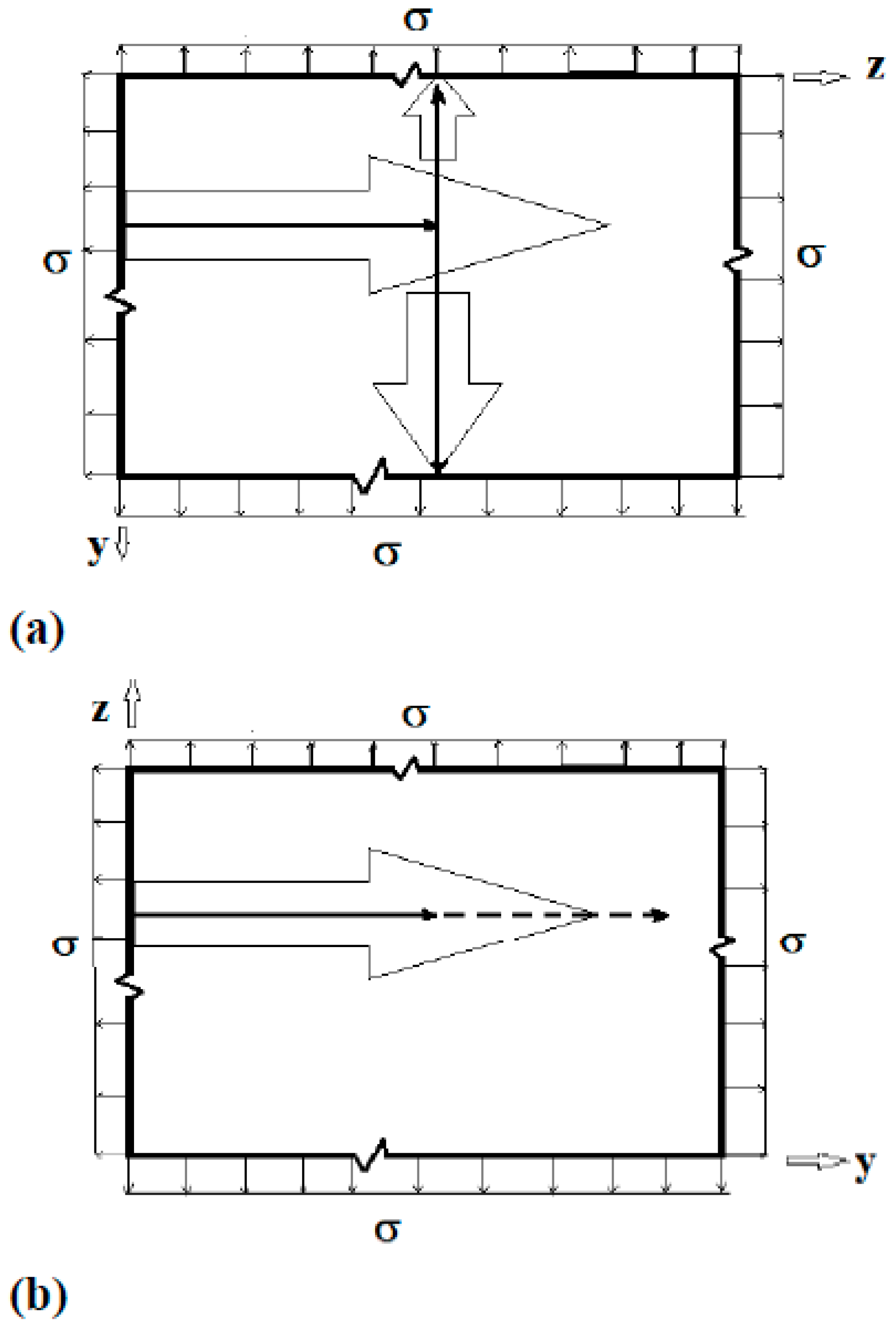
4. Singular Stress Fields in the Vicinity of a (010)[001] Through-Crack Front Propagating under Mode I (Extension/Bending) and Mode II (Sliding Shear/Twisting) in [100] Direction
4.1. Case (a): Complex Roots
4.1.1. Symmetric (Mode I) Loading (Extension/Bending)
4.1.2. Skew-symmetric (Mode II) Loading (Sliding Shear/Twisting)
4.2. Case (b): Imaginary Roots
4.2.1. Symmetric (Mode I) Loading (Extension/Bending)
4.2.2. Skew-symmetric (Mode II) Loading (Sliding Shear/Twisting)
5. Plate Surface Boundary Conditions and Through-Thickness Distribution of Singular Stress Fields
5.1. Satisfaction of traction-free boundary conditions
5.2. Hyperbolic Cosine Distributed Far-Field Loading
6. Stress Intensity Factors and Energy Release Rates for a Through-Thickness Center-Crack (Modes I and II)
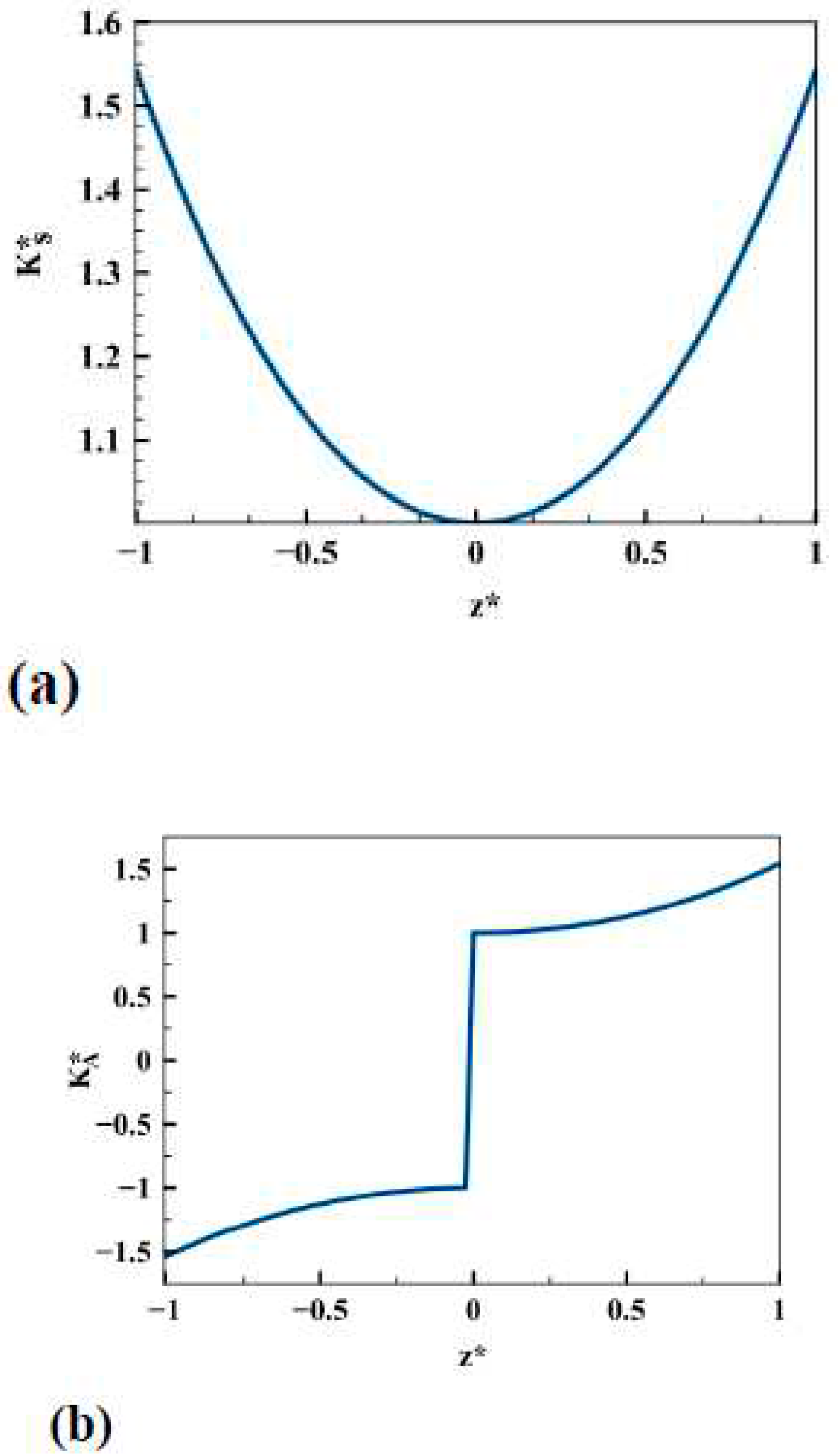
6.1. Through-Thickness Distribution of Stress Intensity Factors (Modes I and II)
6.2. Through-Thickness Distribution of Energy Release Rates (Modes I and II)
7. Necessary and Sufficient Conditions for Easy or Difficult Cleavage Planes
7.1. Crack Deflection Criterion, based on the relative fracture energy
7.2. Comparison of Solutions Involving Complex and Imaginary Roots with Their Isotropic Counterpart
7.2.1. Isotropic Materials:
7.2.2. Solution Involving Complex Roots:
7.2.3. Solution Involving Imaginary Roots
8. Numerical Results and Discussion
9. Summary and Conclusions
- Atomistic scale modeling of cracks requires consideration of both the long-range elastic interactions and the short-range chemical reactions. The Griffith thermodynamic-based theory does not take the latter into account, and hence must be regarded as a necessary condition but not as sufficient.
- The effect of short-range chemical reactions can be adequately captured by the elastic properties-based parameters, such as the inverse anisotropic ratio, λ, or equivalently, the normalized elastic parameter, χ. This is because the elastic properties are controlled by various aspects of the underlying structural chemistry of single crystals, such as the Bravais lattice type, bonding (covalent, ionic, and metallic), bonding (including hybridized) orbitals, electro-negativity of constituent atoms in a compound, polarity, etc.
- More specifically, the elastic properties of superconducting YBa2Cu3O7-σ are strongly influenced by oxygen non-stoichiometry (as well as various structural defects).
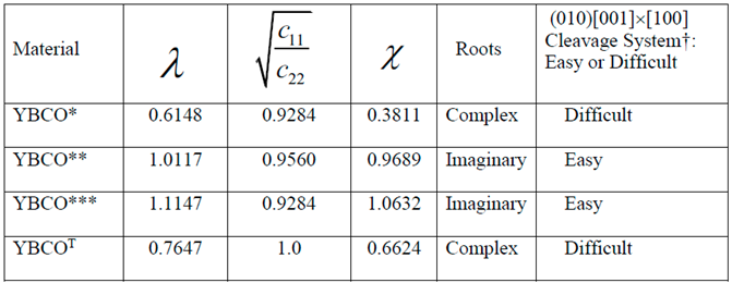
- Similarity or dissimilarity of the present asymptotic solutions involving complex (λ < 1 or equivalently, ) and imaginary roots (λ > 1 or equivalently, ) with their isotropic (λ = 1) counterparts can lead to a sufficient condition for determination of a cleavage system being easy or difficult for crack propagation.
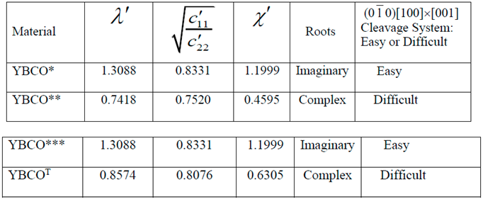
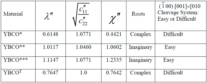
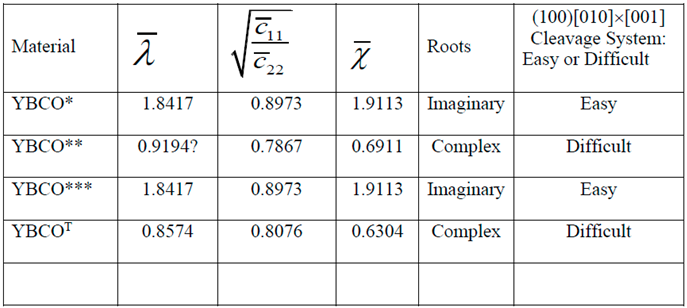
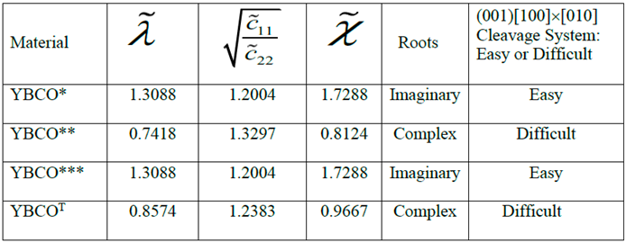
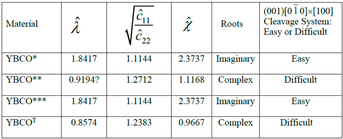
- The normalized elastic parameter, χ, for YBCO* is smaller than , giving rise to complex roots (of the characteristic equation) for a (010)[001] [100] through- crack, weakening a YBCO monocrystalline plate. Same is true for a (00)[001]×[010] crack. These results predict that (010) and (00) are difficult cleavage planes, which are in contradiction with the experimental observations.
- Only for YBCO***, all the cleavage systems are predicted to be easy, which is in agreement with the experimentally observed fracture characteristics, thus ensuring that a reasonably accurate complete set of nine experimentally determined elastic constants has been arrived at, by employing the present theoretical approach.
- For tetragonal YBCOT, all the six cleavage systems investigated here are found to be difficult, thus completely invalidating the values of the corresponding experimentally determined elastic constants reported by Reichard et al. [67].
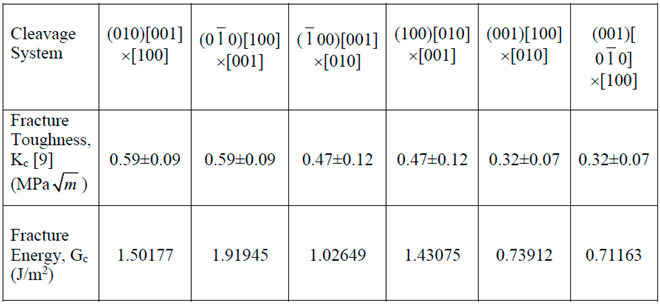
- Finally, generally unavailable results, pertaining to the through-thickness variations of stress intensity factors and energy release rates for a crack corresponding to symmetric and skew-symmetric hyperbolic cosine loads that also satisfy the boundary conditions on the top and bottom surfaces of an orthorhombic monocrystalline plate under investigation, bridge a longstanding gap in the stress singularity/fracture mechanics literature.
Appendix A. Singular Stress Fields in the Vicinity of a (00)[100] Through-Crack Front Weakening an Orthorhombic Single Crystal under Mode I (Extension/Bending) and Mode II (Sliding Shear/Twisting)
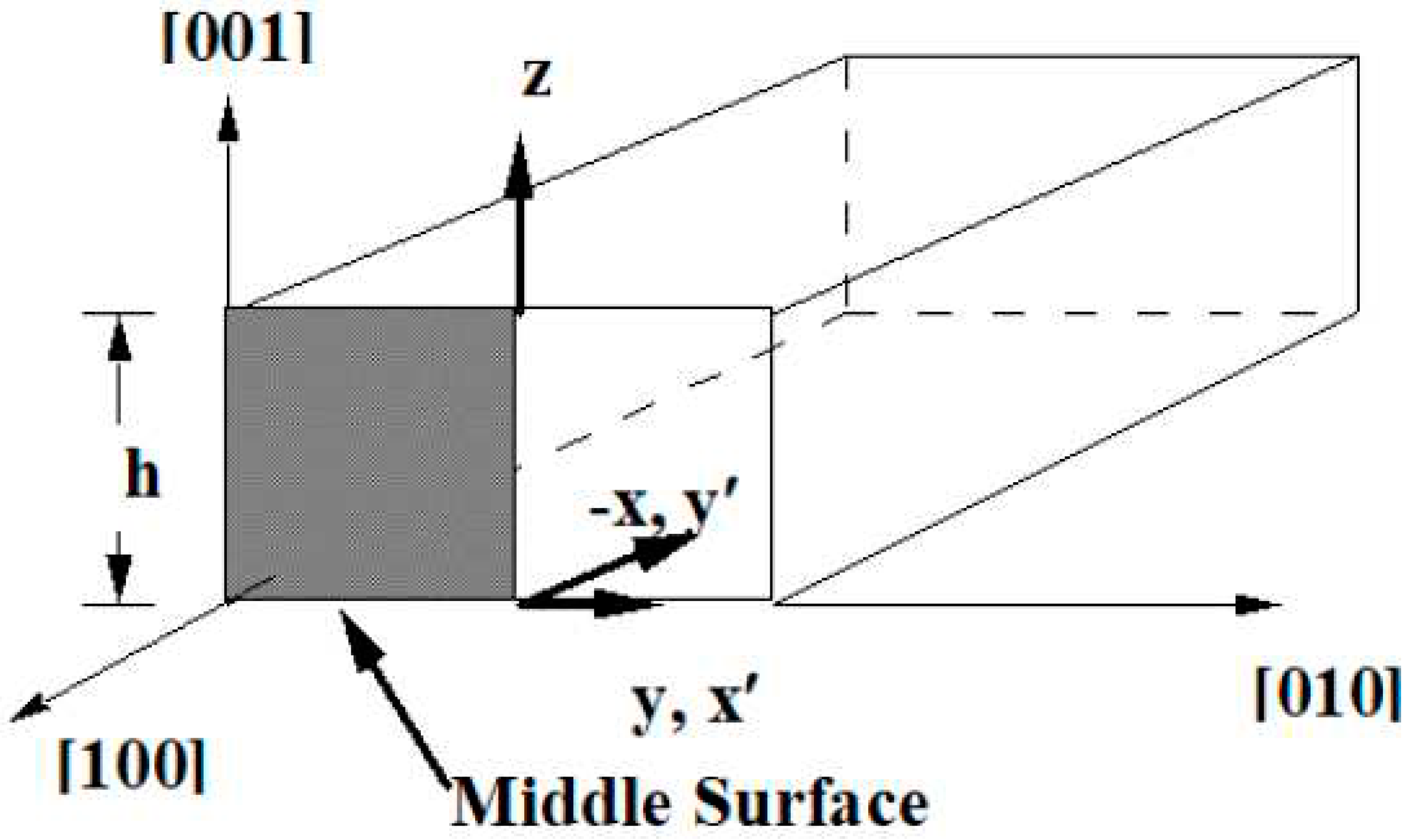
Appendix B. Singular Stress Fields in the Vicinity of a (00)[001] Through-Crack Front Propagating under Mode I (Extension/Bending) and Mode II (Sliding Shear/Twisting) in [010] Direction
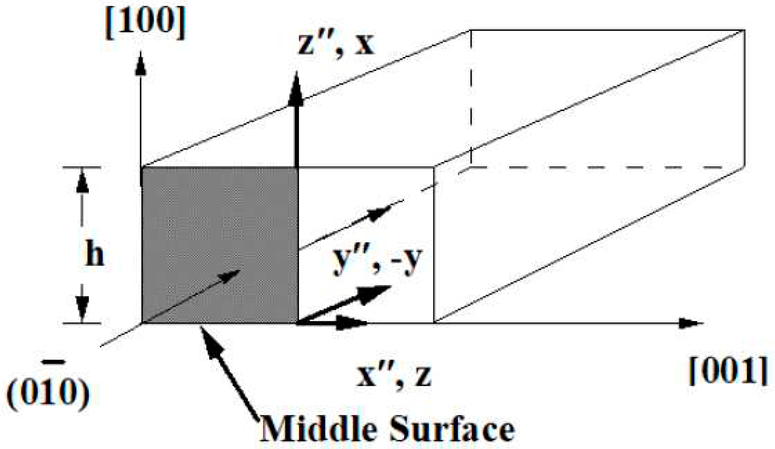
Appendix C. Singular Stress Fields in the Vicinity of a (100)[010] Through-Crack Front Propagating under Mode I (Extension/Bending) and Mode II (Sliding Shear/Twisting) in [001] Direction
Appendix D. Singular Stress Fields in the Vicinity of a (001)[100] Through-Crack Front Propagating under Mode I (Extension/Bending) and Mode II (Sliding Shear/Twisting) in [010] Direction
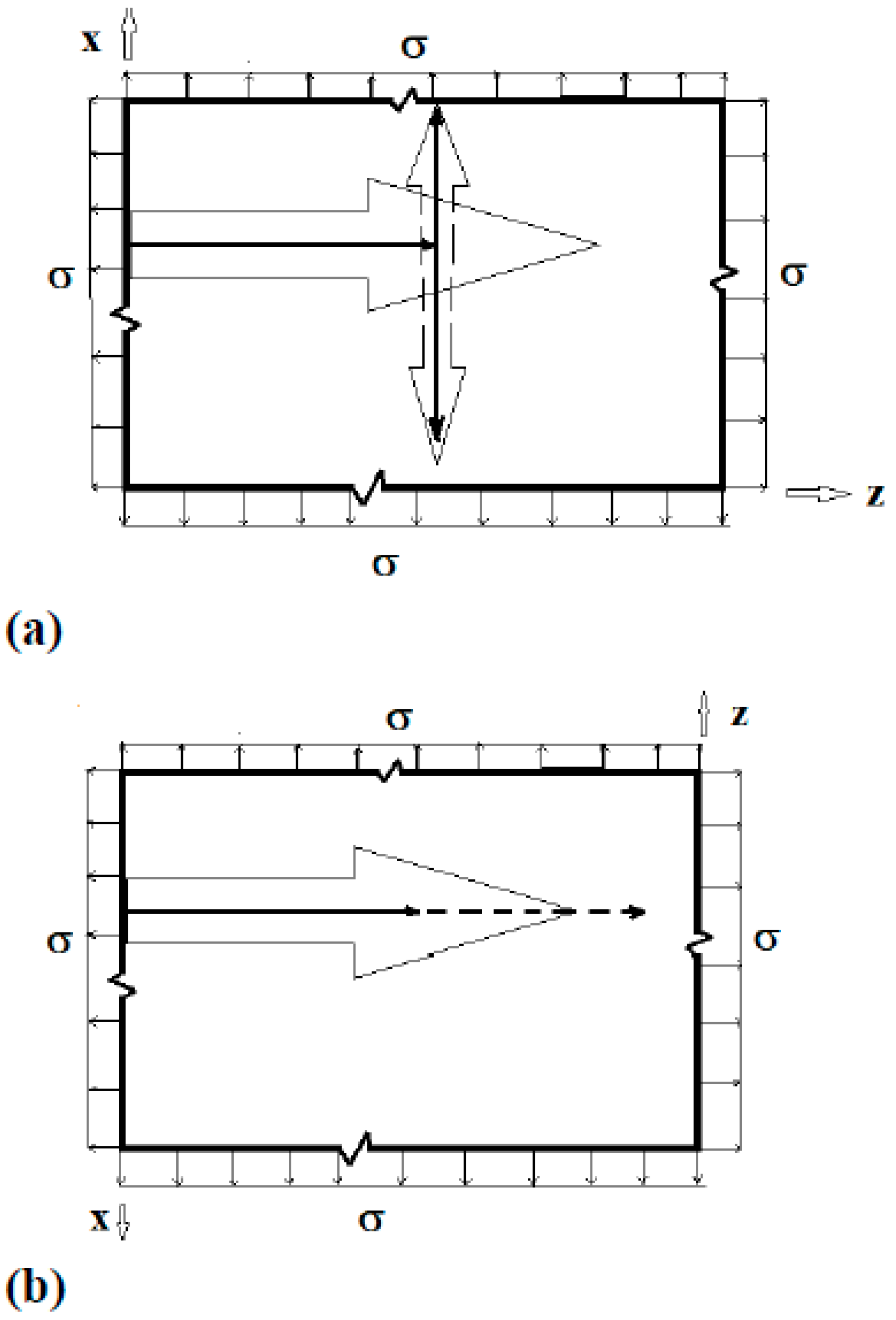
Appendix E. Singular Stress Fields in the Vicinity of a (001)[00] Through-Crack Front Propagating under Mode I (Extension/Bending) and Mode II (Sliding Shear/Twisting) in [100] Direction
References
- Lei M, Sarrao JL, Visscher WM, Bell TM, Thompson JD, Migliori A, Welp UW, Veal, BM. Elastic constants of a monocrystal of superconducting YBa2Cu3O7-δ. Phys. Rev. B 1993; 10: 6154-6156. [CrossRef]
- Bednorz JG, Muller KA. Perovskite-type oxides − the new approach to high-Tc superconductivity. Rev. Mod. Phys. 1988; 60: 585-600. (Nobel Lecture: ©1988 The Nobel Foundation).
- Walker G. Technology: How SQUIDs were found where crystals meet. New Scientist, Issue 1776, July 1991. https://www.newscientist.com/article/mg13117764-900-technology-how-squids-were-found-where-crystals-meet/.
- Grimvall G. The electron-phonon interaction in metals, Vol. XVI of Selected Topics in Solid State Physics; ed. E. P. Wolhfarth, North Holland, Amsterdam, 1981.
- Allen PB. The electron-phonon coupling constant λ. In Handbook of Superconductivity, ed. C. P. Poole, Jr., Ch. 9, Sec. G, pp. 478-483, Academic Press, New York (1999).
- Cook RF, Dinger TR, Clarke DR. Fracture toughness measurements of YBa2Cu3Ox single crystals. Appl. Phys. Lett. 1987; 61: 454-456. [CrossRef]
- Roa JJ, Capdevila XG, Martinez M, Espiell F, Segarra M. Nanohardness and Young’s Modulus of YBCO samples textured by Bridgman technique. Nanotechnology 2007; 18: 385701 (6 pages). [CrossRef]
- Konstantopoulou K, Roa JJ, Jiménez-Piqué E, Segarra M, Pastor JY. Fracture micromechanisms and mechanical behavior of YBCO bulk superconductors at 77 and 300 K. Ceramics Int. 2014; 40(8) Part B: 12797-12806. [CrossRef]
- Raynes AS, Freiman SW, Gayle FW, Kaiser DL. Fracture toughness of YBa2Cu3O6+δ single crystals: Anisotropy and twinning effects. J. Appl. Phys. 1991; 70 (10), 5254-5257. [CrossRef]
- Goyal A, Funkenbusch PD, Kroeger DM, Burns SJ. Anisotropic hardness and fracture toughness of highly aligned YBa2Cu3O7−δ. J. Appl. Phys. 1992; 71(5): 2363-2366. [CrossRef]
- Okudera T, Murakami A, Katagiri K, Kasaba K, Shoji Y, Noto K, Sakai N, Murakami M. Fracture toughness evaluation of YBCO bulk superconductor. Physica C 2003; 392–396: 628–633. [CrossRef]
- Diko P. Cracking in melt-grown RE–Ba–Cu–O single-grain bulk superconductors. Supercond. Sci. Technol. 2004; 17: R45–R58. [CrossRef]
- Congreve JVJ, Shi Y, Huang KY, Dennis AR, John H Durrell JH, Cardwell DA. Characterisation of the mechanical failure and fracture mechanisms of single grain Y–Ba–Cu–O bulk superconductors. Supercond. Sci. Technol. 2020; 33(1): 015003 (9pp). [CrossRef]
- Granozio FM, di Uccio US. Gibbs energy and growth habits of YBCO. J. Alloys and Compounds 1997; 251(1-2): 56-64. [CrossRef]
- Lekhnitskii SG. Anisotropic Plates. Gordon and Breach, New York (1968).
- Stroh AN. Dislocations and cracks in anisotropic elasticity. Phil. Magazine 1958; 7: 625-646. [CrossRef]
- Sih GC, Paris PC, Irwin GR. On cracks in rectilinearly anisotropic solids. Int. J. Fracture Mech. 1965; 1: 189-203. [CrossRef]
- Suo Z, Bao G, Fan B, Wang TC. Orthotropy rescaling and implications for fracture in composites. Int. J. Solids Struct. 1991; 28(2): 235-248. [CrossRef]
- Lin YY, Sung JC. Stress singularities at the apex of a dissimilar anisotropic wedge. ASME J. Appl. Mech.1998; 65: 454-463. [CrossRef]
- Nazarov SA. Stress intensity factors and crack deviation conditions in a brittle anisotropic solid. J. Appl. Mech. Techn. Phys. 2005; 36: 386-394.
- Nejati M, Ghouli S, Ayatollahi MR. Crack tip asymptotic fields in anisotropic planes: Importance of higher order terms. Appl. Math. Modelling 2021; 91: 837-862. [CrossRef]
- Chaudhuri RA. Three-dimensional singular stress field at the front of a crack and lattice crack deviation (LCD) in a cubic single crystal plate. Philosophical Magazine 2010; 90(15), 2049-2113. [CrossRef]
- Kravchenko V. Applied Quaternionic Analysis. Heldermann Verlag (2003).
- Stenger F, Chaudhuri R, Chiu J. Sinc solution of boundary integral form for two-dimensional bi-material elasticity problems. Compos. Sci. Tech. 2000; 60(12-13): 2197–2211. [CrossRef]
- Chaudhuri RA, Xie M. A novel eigenfunction expansion solution for three-dimensional crack problems. Compos. Sci. Tech. 2000; 60(12-13): 2565-2580. [CrossRef]
- Chaudhuri RA. Eigenfunction expansion solutions for three-dimensional rigid planar inclusion problem. Int. J. Fracture 2003; 121(3): 95-110. [CrossRef]
- Chaudhuri RA, Xie M. A tale of two saints: St. Venant and “St. Nick” — Does St. Venant’s principle apply to bimaterial straight edge and wedge singularity problems?. Compos. Sci. Tech. 2000; 60(12-13): 2503–2515. [CrossRef]
- Xie M, Chaudhuri RA. Three-dimensional stress singularity at a bimaterial interface crack front. Compos. Struct. 1997; 40(2): 137-147. [CrossRef]
- Chaudhuri RA, Xie M. Free-edge stress singularity in a bimaterial laminate. Compos. Struct. 1997; 40(2): 129-136. [CrossRef]
- Chaudhuri RA, Chiu SHJ. Three-Dimensional Asymptotic Stress Field in the Vicinity of an Adhesively Bonded Scarf Joint Interface. Compos. Struct. 2009; 89(3): 475-483. [CrossRef]
- Xie M, Chaudhuri RA. Three-dimensional asymptotic stress field at the front of a bimaterial wedge of symmetric geometry under antiplane shear loading. Compos. Struct. 2001; 54(4): 509-514. [CrossRef]
- Chiu JSH, Chaudhuri RA. Three-dimensional asymptotic stress field at the front of an unsymmetric bimaterial pie-shaped wedge under antiplane shear loading. Compos. Struct. 2002; 58(1): 129-137. [CrossRef]
- Chaudhuri RA, Chiu SHJ. Three-dimensional asymptotic stress field at the front of an unsymmetric bimaterial wedge associated with matrix cracking or fiber break. Compos. Struct. 2007; 78(2): 254-263. [CrossRef]
- Chiu SHJ, Chaudhuri RA. A three-dimensional eigenfunction expansion approach for singular stress field near an adhesively-bonded scarf joint interface in a rigidly-encased plate. Eng. Fracture Mech. 2011; 78 (10): 2220-2234. [CrossRef]
- Chaudhuri RA. Three-dimensional singular stress field near a partially debonded cylindrical rigid fiber. Compos. Struct. 2006; 72(2): 141-150. [CrossRef]
- Chaudhuri RA. Three-dimensional asymptotic stress field in the vicinity of the circumferential tip of a fiber-matrix interfacial debond. Int. J. Eng. Sci. 2004; 42(15-16): 1707-1727. [CrossRef]
- Chaudhuri SN, Chaudhuri RA, Benner RE, Penugonda M. Raman spectroscopy for characterization of interfacial debonds between carbon fibers and polymer matrices. Compos. Struct. 2006; 76(4): 375-387. [CrossRef]
- Chaudhuri RA, Xie M. On three-dimensional asymptotic solution, and applicability of Saint–Venant’s principle to pie-shaped wedge and end face (of a semi-infinite plate) boundary value problems. Eng. Fracture Mech. 2015; 142, 93-107; see also Corrigendum Eng. Fracture Mech. 2019; 217: 106506. [CrossRef]
- Chaudhuri RA. On applicability and uniqueness of the correspondence principle to pie-shaped wedge (“wedge paradox”) with various boundary conditions. Eng. Fracture Mech. 2020; 231: 106991. [CrossRef]
- Chaudhuri RA, Chiu SHJ. Three-dimensional singular stress field near the interfacial bond line of a tapered jointed plate either free-standing (notch) or (fully/partially) attached to a super-rigid inclusion (antinotch). Eng. Fracture Mech. 2012; 91: 87-102. [CrossRef]
- Chaudhuri RA. Three-dimensional singular stress fields near the circumferential junction corner line of an island/substrate system either free-standing or fully/partially bonded to a rigid block. Eng. Fracture Mech. 2013; 107: 80-97. [CrossRef]
- Chaudhuri RA. Three-dimensional asymptotic stress field in the vicinity of the circumference of a penny shaped discontinuity. Int. J. Solids Struct. 2003; 40(13-14): 3787-3805. [CrossRef]
- Chaudhuri RA. Three-dimensional asymptotic stress field in the vicinity of the circumference of a bimaterial penny shaped interface discontinuity. Int. J. Fracture 2006; 141(1-2): 207-221. [CrossRef]
- Chaudhuri RA. Three-dimensional asymptotic stress field in the vicinity of the line of intersection of a circular cylindrical through/part-through open/rigidly plugged hole and a plate. Int. J. Fracture 2003; 122(1): 65-88. [CrossRef]
- Chaudhuri RA. Three-dimensional asymptotic stress field in the vicinity of the line of intersection of an inclusion and plate surface. Int. J. Fracture 2002; 117(3): 207-233. [CrossRef]
- Chaudhuri RA. An eigenfunction expansion solution for three-dimensional stress field in the vicinity of the circumferential line of intersection of a bimaterial interface and a hole. Int. J. Fracture 2004; 129(4): 361-384. [CrossRef]
- Yoon J, Chaudhuri RA. Three-dimensional asymptotic antiplane shear stress fields at the front of interfacial crack/anticrack type discontinuities in trimaterial bonded plates. Compos. Struct. 2011; 93 (6): 1505-1515. [CrossRef]
- Yoon J, Chaudhuri RA. Three-dimensional asymptotic stress fields at the front of a trimaterial junction. Compos. Struct. 2012; 94 (2): 337-350. [CrossRef]
- Chaudhuri RA, Yoon, J. Three-dimensional asymptotic mode I/II stress fields at the front of interfacial crack/anticrack discontinuities in trimaterial bonded plates. Compos. Struct. 2012; 94 (2): 351-362. [CrossRef]
- Kaczynski, A. and Kozlowski, W. Thermal stresses in an elastic space with a perfectly rigid flat inclusion under perpendicular heat flow. Int. J. Solids Struct. 2009; 46: 1772-1777. [CrossRef]
- Willis JR. The penny shaped crack on an interface. Quart. J. Mech. Appl. Math. 1972; 25: 367-385. [CrossRef]
- Folias ES. On interlaminar stresses of a composite plate around the neighborhood of a hole. Int. J. Solids Struct. 1989; 25(10), 1193-1200. [CrossRef]
- Folias ES. Boundary layer effects of interlaminar stresses adjacent to a hole in a laminated composite plate. Int. J. Solids Struct. 1992; 29(2), 171-186. [CrossRef]
- Folias ES. On the stress singularities at the intersection of a cylindrical inclusion with the free surface of a plate. Int. J. Fracture 1989; 39: 25-34. [CrossRef]
- Chaudhuri RA. On through-thickness distribution of stress intensity factors and energy release rates in the vicinity of crack fronts. Eng. Fracture Mech. 2019; 216: 106478. [CrossRef]
- Chaudhuri RA. Three-dimensional singular stress field at the front of a crack weakening a unidirectional fiber reinforced composite plate. Compos. Struct. 2011; 93(2): 513-527. [CrossRef]
- Chaudhuri RA. On three-dimensional singular stress field at the front of a planar rigid inclusion (anticrack) in an orthorhombic mono-crystalline plate. Int. J. Fracture 2012; 174(2): 103-126. [CrossRef]
- Chaudhuri RA. Three-dimensional mixed mode I+II+III singular stress field at the front of a (111)[112]×[110] crack weakening a diamond cubic mono-crystalline plate with crack turning and step/ridge formation. Int. J. Fracture 2014; 187(1): 15-49. [CrossRef]
- Chaudhuri RA. On three-dimensional singular stress/residual stress fields at the front of a crack/anticrack in an orthotropic/orthorhombic plate under anti-plane shear loading. Compos. Struct. 2010; 92(8): 1977-1984. (also, Erratum, Compos. Struct. 2011; 93(2): 1058. Doi: 10.1016/j.compstruct.2010.09.010). [CrossRef]
- Chaudhuri RA. Three-dimensional stress/residual stress fields at crack/anticrack fronts in monoclinic plates under antiplane shear loading. Eng. Fracture Mech. 2012; 87: 16-35. [CrossRef]
- Yoon J, Chaudhuri RA. Three-dimensional singular antiplane shear stress fields at the fronts of interfacial crack/anticrack/contact type discontinuities in tricrystal anisotropic plates. Eng. Fracture Mech. 2013; 102: 15–31. [CrossRef]
- Eshelby JD, Read WT, Shockley W. Anisotropic elasticity with application to dislocation theory. Acta Metall. 1953; 1: 251-259. [CrossRef]
- Chaudhuri RA. Comparison of stress singularities of kinked carbon and glass fibers weakening compressed unidirectional composites: a three-dimensional trimaterial junction stress singularity analysis. Phil. Magazine 2014; 94(7): 625-667. [CrossRef]
- Chaudhuri RA, Xie M, Garala HJ. Stress singularity due to kink band weakening a unidirectional composite under compression. J. Compos. Materials 1996; 30(6): 672-691. [CrossRef]
- Alexandrov IV, Goncharov AF, Stishov SM. State equation and compressibility of YBa2Cu3Ox high temperature superconductor monocrystals under pressure to 20 GPa. Pis’ma Zh. Eksp. Teor. Fiz. 1988; 47(7): 357-360.
- Golding B, Haemmerle WH, Schneemeyer LF, Waszczak JV. Gigahertz ultrasound in single crystal superconducting YBa2Cu3O7. IEEE 1988 Ultrasonics Symp. Proc. Chicago, IL, 1988; vol.2: 1079-1083. [CrossRef]
- Reichardt W, Pintschovius L, Hennion B, Collin F. Inelastic neutron scattering study of YBa2Cu3O7-x. Supercond. Sci. Tech. 1988; 1(4): 173-176. [CrossRef]
- Baumgart P, Blumenröder S, Erle A, Hillebrands B, Güntherodt G, Schmidt H. Sound velocities of YBa2Cu3O7−δ single crystals measured by Brillouin spectroscopy, Solid State Comm. 1989; 69(12): 1135-1137. [CrossRef]
- Baumgart P, Blumenröder S, Erle A, Hillebrands B, Splittgerber P, Güntherodt G, Schmidt H. Sound velocities of YBa2Cu3O7−δ and Bi2Sr2CaCu2Ox single crystals measured by Brillouin spectroscopy. Physica C: Supercond. Its Applic. 1989; 162–164, Part 2: 1073-1074. [CrossRef]
- Saint-Paul M, Tholence JL, Noel H, Levet JC, Potel M, Gougeon P. Ultrasound study on YBa2Cu3O7−δ and GdBa2Cu3O7−δ single crystals. Solid State Comm. 1989; 69(12): 1161-1163. [CrossRef]
- Saint-Paul M, Henry JY. Elastic anomalies in YBa2Cu3O7−δ single crystals. Solid State Communications 1989; 72(7): 685-687. [CrossRef]
- Zouboulis E, Kumar S, Chen CH, Chan SK, Grimsditch M, Downey J, McNeil L, Surface waves on the a, b and c faces of untwinned single crystals of YBa2C3O7−δ. Physica C: Superconductivity 1992; 190(3): 329-332. [CrossRef]
- Ledbetter H, Lei M. Monocrystal elastic constants of orthotropic Y1Ba2Cu3O7: An estimate. J. Mater. Res. 1991; 6: 2253-2255. [CrossRef]
- Migliori A, et al. Elastic constants and specific-heat measurements on single crystals of La2CuO4. Phys. Rev. B 1990; 41: 2098-2102. [CrossRef]
- Migliori A, et al. Complete elastic constants and giant softening of c66 in superconducting La1.86Sr0.14CuO4. Phys. Rev. Lett. 1990; 64(20): 2458-2461. [CrossRef]
- Kunukkasseril VX, Chaudhuri RA, Balaraman K. A method to determine 18 rigidities of layered anisotropic plates. J. Fibre Sci. Tech. 1975; 8(4), 303-318. [CrossRef]
- Chaudhuri RA, Balaraman K. A novel method for fabrication of fiber reinforced plastic laminated plates. Composite Structures 2007; 77(2): 160-170. [CrossRef]
- Chaudhuri RA, Balaraman K, Kunukkasseril VX. A combined theoretical and experimental investigation on free vibration of thin symmetrically laminated plates. Composite Structures 2005; 67(1): 85-97. [CrossRef]
- Riddle J, Gumbsch P, Fischmeister HF. Cleavage Anisotropy in Tungsten Single Crystals. Phys. Rev. Lett. 1996; 76(19): 3594-3597. [CrossRef]
- Carslaw HS. Introduction to the Theory of Fourier Series and Integrals. 3rd edn., Dover, New York (1930).
- Wilcox CH. Uniqueness theorems for displacement fields with locally finite energy in linear elastostatics. J. Elasticity 1979; 9: 221-243. [CrossRef]
- Sedov LI. Similarity and Dimensional Methods in Mechanics. Mir Publishers, Moscow (1982).
- Perez R, Gumbsch P. Directional anisotropy in the cleavage fracture of silicon. Phys. Rev. Lett. 2000; 84: 5347-5350. [CrossRef]
- Kermode JR, Albaret T, Sherman D, Bernstein N, Gumbsch P, Payne MC, Csányi G, De Vita A. Low-speed fracture instabilities in a brittle crystal. Nature 2008; 455: 1224-1227. [CrossRef]
- Newnham RE. Structure-Property Relations. Springer-Verlag, New York (1975).
- Pauling L. The Chemical Bond. Cornell Univ. Press, Ithaca, New York (1967).
- Cotton FA, Wilkinson G. Advanced Inorganic Chemistry. 4th edn., John Wiley & Sons, New York (1980).
- Williams A, Kwei GH, Von Dreele RB, Raistrick ID, Bish DL. Joint x-ray and neutron refinement of the structure of superconducting YBa2Cu3O7−x: Precision structure, anisotropic thermal parameters, strain, and cation disorder. Phys. Rev. B 1988; 37:7960(R). [CrossRef]
- Ledbetter H. Elastic constants of polycrystalline Y1Ba2Cu3Ox. J. Mater. Res. 1992; 7: 2905. [CrossRef]
- Lin S, Lei M, Ledbetter H. Elastic constants and Debye temperature of Y1Ba2Cu3Ox: effect of oxygen content. Mater. Lett. 1993; 16: 165. [CrossRef]
- Lubenets SV, Natsik VD, Fomenko LS, Kaufman HJ, Bobrov VS, Izotov AN. Influence of oxygen content and structural defects on low temperature mechanical properties of high temperature superconducting single crystals and ceramics. Fizika Nizkik Temperatur 1997; 23(8): 902-908.
- Streiffer SK, Lairson BM., Eom CB, Clemens BM, Bravman JC, Geballe TH. Microstructure of ultrathin films of YBa2Cu3O7− δ on MgO. Phys. Rev. B 1991; 43: 13007. [CrossRef]
- Fowler DE, Brundle C.R., Lerczac J, Holtzberg FJ. Core and valence XPS spectra of clean, cleaved single crystals of YBa2Cu3O7. Electron Spectroscopy and Related Phenomena 1990; 52: 323-339. [CrossRef]
- Tanaka S, Nakamura T, Tokuda H, Iiyama M. All in situ deposition and characterization of YBa2Cu3O7−x thin films by low-energy electron diffraction and low-energy ion scattering spectroscopy. Appl. Phys. Lett. 1993; 62: 3040. [CrossRef]
- Lin CT, Liang WY. Etch defects in YBa2Cu3O7− δ single crystals grown from flux. Physic C, 1994; 225: 275-286. [CrossRef]
- Lawn B. Fracture of Brittle Solids. 2nd. edn., Camb. Univ. Press (1993).
- Anstis GR, Chantikul P, Lawn BR, Marshall DB. A critical evaluation of indentation techniques for measuring fracture toughness I. J. Am Ceramic Soc. 1981; 64(9): 533-538.
- Roa JJ, Capdevila XG, Segarra M. Mechanical characterization at nanometric scale of ceramic superconductor composites. Int. J. Condens. Matter Adv. Mater. Supercond. Res. 2011; 10(3/4): 217-307.
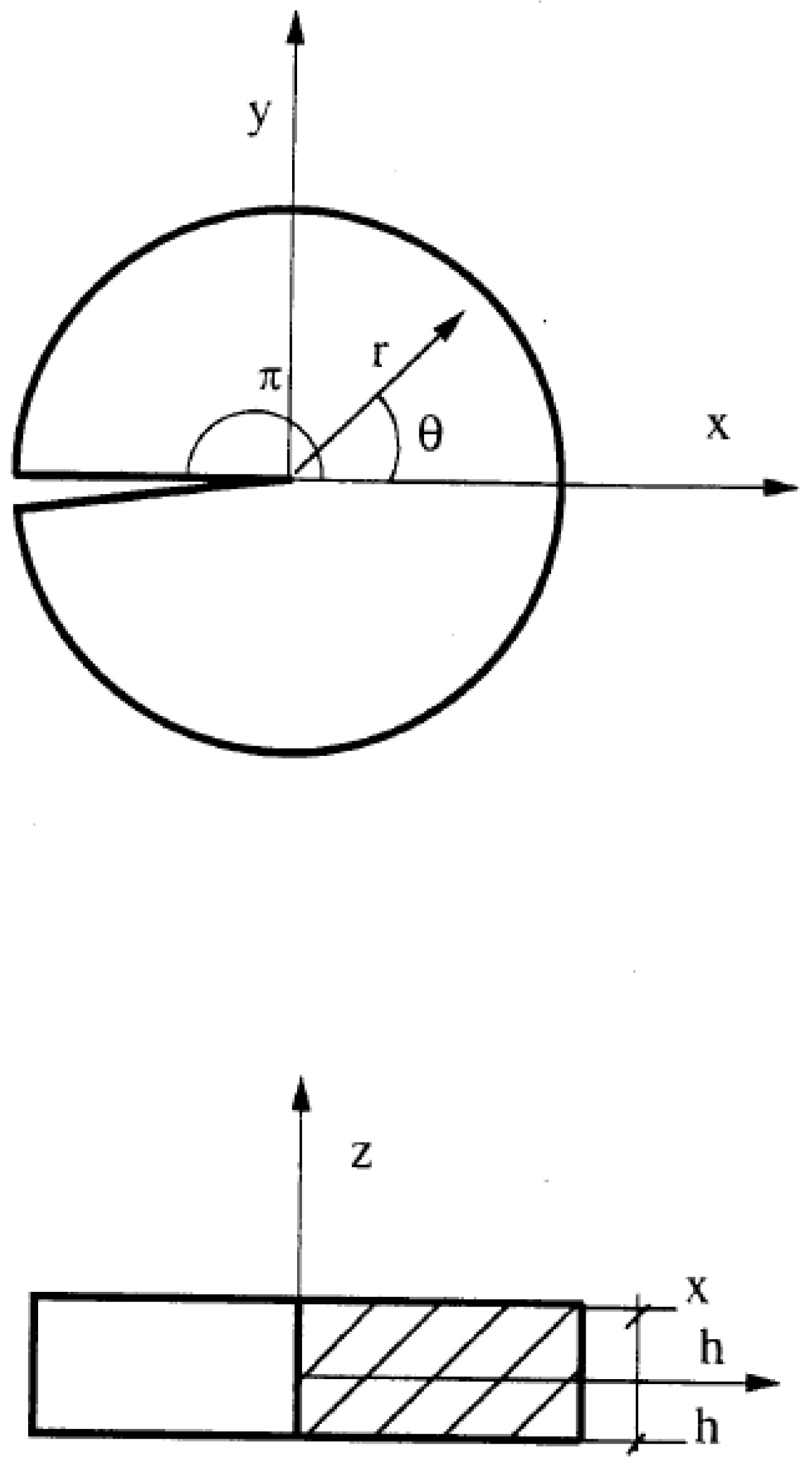

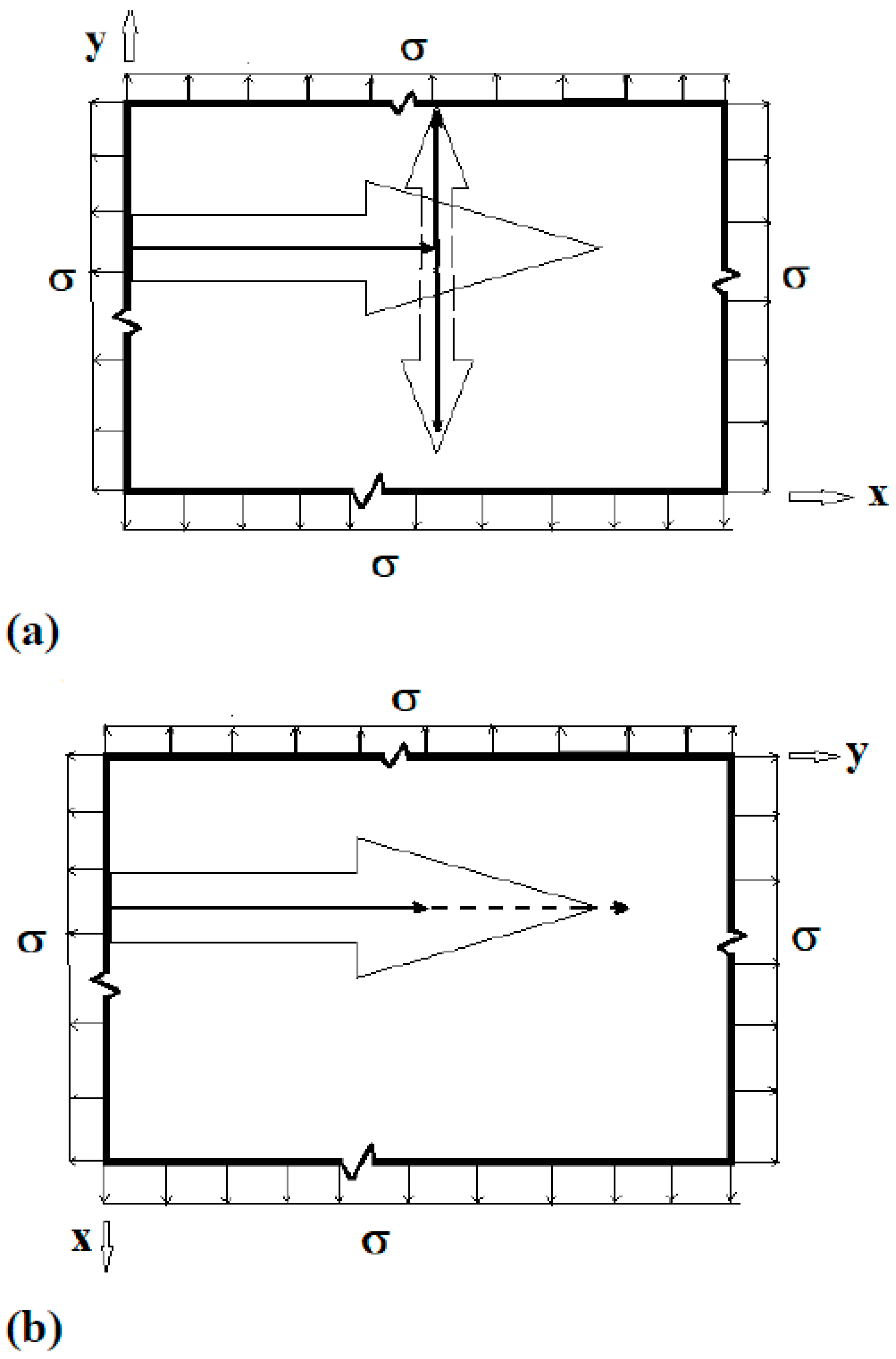
| Material (Technique) |
1. c11 2. (GPa) |
3. 4. (GPa) |
5. c13 6. (GPa) |
7. c22 8. (GPa) |
9. c23 10. (GPa) |
11. c33 12. (GPa) |
13. c44 14. (GPa) |
15. c55 16. (GPa) |
17. 18. (GPa) |
| YBCO* [1] (Resonant Ultrasound) |
19. 231.0 | 20. 132.0 | 21. 71.0 | 22. 268.0 | 23. 95.0 | 24. 186.0 | 25. 49.0 | 26. 37.0 | 27. 95.0 |
| YBCO** [73](Estimate) | 28. 223.0 | 29. 37.0 | 30. 89.0 | 31. 244.0 | 32. 93.0 | 33. 138.0 | 34. 61.0 | 35. 47.0 | 36. 97.0 |
| YBCO***(Inference) | 37. 231.0 | 38. 66.0 | 39. 71.0 | 40. 268.0 | 41. 95.0 | 42. 186.0 | 43. 49.0 | 44. 37.0 | 45. 82.0 |
| Material (Technique) |
46. c11 47. (GPa) |
48. 49. (GPa) |
50. c13 51. (GPa) |
52. c22 53. (GPa) |
54. c23 55. (GPa) |
56. c33 57. (GPa) |
58. c44 59. (GPa) |
60. c55 61. (GPa) |
62. 63. (GPa) |
| YBCOT [67] (Neutron Scattering) | 64. 230.0 | 65. 100.0 | 66. 100.0 | 67. 230.0 | 68. 100.0 | 69. 150.0 | 70. 50.0 | 71. 50.0 | 72. 85.0 |
Disclaimer/Publisher’s Note: The statements, opinions and data contained in all publications are solely those of the individual author(s) and contributor(s) and not of MDPI and/or the editor(s). MDPI and/or the editor(s) disclaim responsibility for any injury to people or property resulting from any ideas, methods, instructions or products referred to in the content. |
© 2023 by the authors. Licensee MDPI, Basel, Switzerland. This article is an open access article distributed under the terms and conditions of the Creative Commons Attribution (CC BY) license (http://creativecommons.org/licenses/by/4.0/).


