Preprint
Article

Oscillations Analysis and Control Optimization of Hydraulic Turbine Based on Variable Speed Reaching Law

Altmetrics

Downloads

156

Views

46

Comments

0

This version is not peer-reviewed

Submitted:

15 March 2023

Posted:

16 March 2023

You are already at the latest version

Alerts
Abstract
Hydro generator sets serve as the peak and frequency regulation of the power system,and play a very important role in maintaining system stability and improving power quality.Based on the internal characteristics model of a specific type of hydro generator,this paper constructs a hydroelectric coupling model for hydropower units,studies the influence of the regulation system of hydropower units on low-frequency oscillations under different load conditions,and adopts variable speed reaching law and fuzzy sliding mode control strategy to improve the regulation quality of the system and ensure the stable operation of the units.Results of simulation and water turbine set under different load conditions show that varible speed reaching law can effectively improve the power-angle oscillation behavior of the hydropower set and suppress the occurrence of low-frequency oscillations of the system when the system is subject to power disturbance,which provide a new theoretical basis and solution for the vibration analysis and control optimization of hydraulic turbine units.
Keywords: 
Subject: Engineering  -   Control and Systems Engineering

1. INTRODUCTION

The hydroturbine generator set can be started quickly and connected to the grid,and has good regulating performance.It plays a very important role in maintaining the stability of the system and improving the power quality.Based on the reality of variable working conditions of hydropower units,this paper focuses on the stability of power angle of hydropower units,reveals the influence of turbine on the stability of power system oscillation through mechanism analysis,and uses advanced control strategy to mine the regulating potential force of HTRS.It has a certain innovative and practical application value to further understand the inducement of low-frequency oscillation of hydropower units,and improve the capacity of hydropower delivery.Furthermore,it can improve the efficiency of unit operation and maintain the stability of power system.

2. MATHEMATICAL MODEL OF HYDRAULIC SYSTEM

2.1. Mathematical model of hydraulic system

2.1.1. Mathematical model of water turbine

Hydraulic turbine is an important part of HTRS,which has strong nonlinear characteristics.Under the condition that the turbine operating condition changes slowly,the steady state characteristic can be used to approximate the dynamic characteristic,it can be expressed by the linearized hydraulic turbine internal characteristic model as shown in Figure 1.
The steady state equation of the hybrid turbine can be described as Equ.(1),Equ.(2) [1,2,3,4].
Q = Ω r 0 2 + 9.8 η H Ω ctg α 2 π b o + r 0 ctg β 0 F
M t = Q ctg α 2 π b 0 + r 0 ctg β 0 F Q W r 0 2
Where:
Q -the flow rate of the hydraulic turbine;
M t -the mechanical torque;
H -the hydraulic turbine head;
Ω -the angular velocity of the rotor;
r 0 -the radius of the flow surface in the middle of the runner;
F- the outlet area of the runner;
b 0 -the installation height of guide vane;
β 0 -the outlet angle of the middle flow surface of the runner;
α -the outflow angle of guide vane.
By linearizing and standardizing Equ.(1) and Equ.(2),the calculation formula of turbine transfer coefficient based on internal characteristic method can be obtained as follows.
e q y = a Y r Q r ( 1 + a c ) 2 π b 0 r 0 2 k 0 ω r · q 0 2 cos 2 α 0 ω 0 e q x = q 0 ( a 1 ) ω 0 ( 1 + a c ) , e q h = q 0 h 0 ( 1 + a c ) e y = b e q y , e x = b e q x m t 0 ω 0 , e h = b e q h + m t 0 h 0 .
There are:
α = ω 0 2 η 0 h 0 · 0.353 D 1 2 ω r 2 9.81 H r , b = ( 1 + c ) m t 0 q 0 , c = 2 q 0 q q * Q r 2 2 d η 0 q 0 q * 2 Q r 2 , k 0 = ( d y / d α ) 0 , q 0 = Q 0 Q r , h 0 = H 0 H r , m t 0 = M t 0 M t r , ω 0 = Ω 0 Ω γ , η = η * q q * 2 Q r 2 2 d .
Where:
D 1 -the diameter of the turbine runner/m;
D -the constant related to the geometric parameters of the pipeline;
η -the approximate relationship between turbine flow rate and turbine efficiency;
r -the actual value under rated working condition;
0 -the actual value under steady state;
* -the optimal working condition of the turbine.
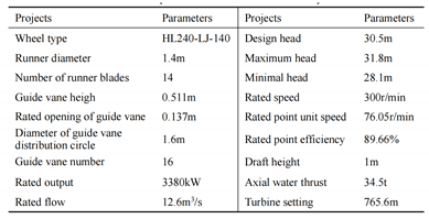
Taking HL240-LJ-140 hybrid turbine as the research object,the relationship between turbine load and transfer coefficient is calculated.
The basic parameters of the turbine are shown in Table 1 and Table 2 show the variation of turbine transfer coefficient with load under rated head calculated by internal characteristic method.Where P represents the turbine load (output),when the rated load is taken as P=1p.u.,then the working condition serial numbers 1-4 represent the working condition of 30%,50%,70% and 90% rated load(output) respectively.

2.1.2. Comprehensive mathematical model of hydraulic system

The equation of state of the hydraulic system considering the effect of elastic water hammer is as follows [5,6]:
x ˙ 1 = 1 T y + 8 e q h T w T r 2 · x 1 + x 2 8 e q x e h T w T r 2 · Δ ω + e y T y · Δ u x ˙ 2 = 8 e q h T w + T y T r 2 T y · x 1 + x 3 8 e q x e h T w T r 2 T y · Δ ω + 8 e q h e y + e q y e h T w T r 2 T y · Δ u x ˙ 3 = 8 T r 2 T y x 1 + 8 e y T r 2 T y · Δ u
Δ m t = x 1 + e x Δ ω
Among them, x 1 , x 2 and x 3 are intermediate variables, which are used to characterize the connection among the hydraulic turbine,pressure water diversion pipe and servo mechanism.

2.2. Mathematical model of generator

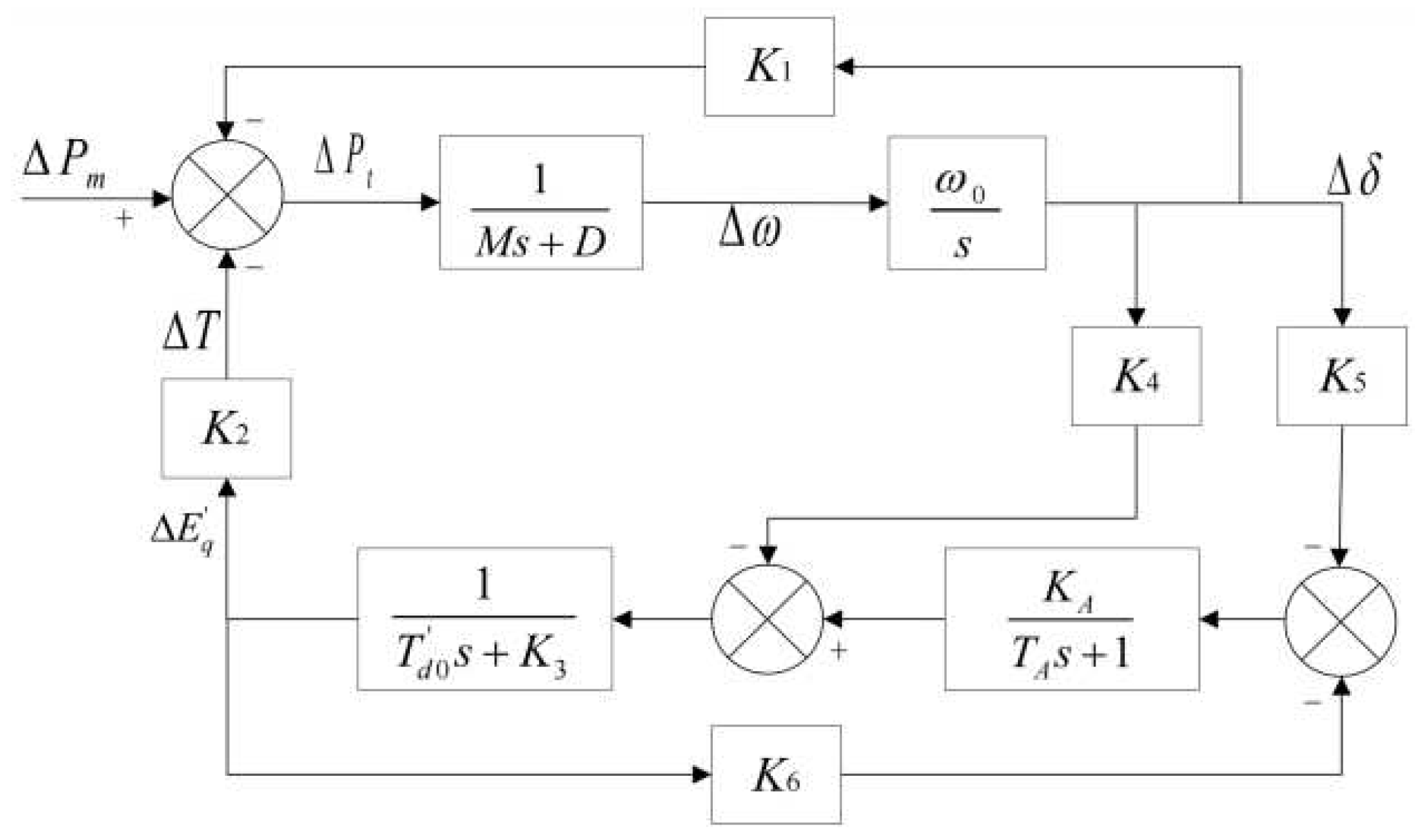
Philphils-heffron model of single-machine infinite system is the basis of damping torque analysis,which ignores the transient state of stator winding group and damping windings.The generator adopts the third-order practical model,and the excitation system uses the static excitation system represented by the first-order inertia link.By linearizing the system at the stable point,the linearized differential equation can be obtained as followed [7,8,9,10,11].
Δ δ ˙ = ω 0 Δ ω Δ ω ˙ = 1 M Δ P m Δ P e D Δ ω Δ E ˙ q = 1 T d 0 Δ E f d Δ E q Δ E f d = 1 T A · Δ E f d K A T A · Δ V t Δ P e = K 1 Δ δ + K 2 Δ E q Δ E q = K 3 Δ E q + K 4 Δ δ Δ V t = K 5 Δ δ + K 6 Δ E q
There have:
K 1 = E q 0 V b X d Σ cos δ 0 V b 2 X q X d X d Σ X q Σ cos 2 δ 0 K 2 = V b X d Σ sin δ 0 , K 3 = X d Σ X d Σ K 4 = X d X d V b X d Σ sin δ 0 K 5 = V t d 0 X q V b cos δ 0 V t o X q Σ V t q 0 X d V b 0 sin δ 0 V t o X d Σ K 6 = V t q 0 X t V t 0 X d Σ
In Equ.(7),the symbol Δ represents the small increment of the corresponding variable,and the subscript 0 represents the value of the corresponding variable at the steady-state operating point.And K 3 is a constant, K 1 , K 2 and K 4 - K 6 under different load conditions are shown in Table 3 [12,13,14,15].
The linearized infinite Phillips-Heffron model for a single machine can be obtained from Equ.(7) [16,17,18,19] and Equ(8) were shown in Figure 2.

2.3. Mathematical model of regulating system of hydropower unit

The state space model of hydropower unit regulation system is as follows:
X ˙ = A X + B Δ u X = Δ δ Δ ω Δ E q Δ E f d x 1 x 2 x 3 T
A = 0 ω 0 0 0 0 0 0 K 1 M e x D M K 2 M 0 1 M 0 0 K 4 T d 0 0 K 3 T d 0 1 T d 0 0 0 0 K A K 5 T A 0 K A K 6 T A 1 T A 0 0 0 0 8 e q x e h T w T r 2 0 0 1 T y 8 e q h T w T r 2 1 0 0 8 e q x e h T w T r 2 T y 0 0 8 e q h T w + T y T r 2 T y 0 1 0 0 0 0 8 T r 2 T y 0 0
B = 0 0 0 0 e y T y 8 e q h e y e q y e h T w T y 2 T y 8 e y T y 2 T y T

3. DESIGN OF FUZZY SLIDING MODE CONTROLLER FOR REGULATING SYSTEM OF HYDROPOWER UNIT

The transfer coefficient of the turbine will change with the change of the turbine output, and this change has a non-negligible influence on the stability of the system.At present,the widely used conventional PID controller has a relatively fixed structure and parameters,poor adaptability to system parameter perturbation,and a lack of tracking ability,which is difficult to meet the increasing control requirements under the increasing size of the power grid [20,21,22,23]. The sliding mode controller is insensitive to the changes of system internal parameters and external disturbances,and has strong tracking ability and robust performance.It has a good application prospect for solving complex control problems of hydropower units.

3.1. Conventional sliding mode controller

In the past design of sliding mode controller for power system,tracking error function is usually used to design sliding mode surface in order to reduce the complexity of calculation [24,25,26,27].
s = c e + e ˙
Where c is constant and k>0.At the same time,the commonly used approach law form is:
S ˙ = c Δ ω ˙ d Δ ω ˙ + Δ ω ¨ d Δ ω ¨ = ε sgn ( s )
Where ε is a constant and ε 0,whose size represents the approaching speed of the system moving point to the sliding mode surface.The larger ε is,the faster the approaching speed is,and the smaller ε is,the longer the time it takes for the system moving point to reach the sliding mode surface,sgn(s) is a sign function, and its specific expression is as follows [28].
sgn ( s ) = 1 s > 0 0 s = 0 1 s < 0
Taking the derivative of sliding mode functions in Equ.(9) with respect to time t, we can obtain:
s ˙ = c e ˙ + Δ ω ¨ d f ( X ) e y M T y Δ u
If s ˙ =0,the control law of sliding mode controller can be obtained as follows [29,30,31]:
u n S M C = Δ u = M T y e y c e ˙ + Δ ω ¨ d f ( X ) + ε sgn ( s ) = u e q + u s w
u e q is the equivalent control law,which is used to maintain the operating point of the system on the sliding mode surface. u s w is the switching control rate,which is used to guide the system operating point to the designed sliding surface.

3.2. Improved sliding surface

The electrical characteristics of the generator are introduced into the design of sliding mode function to reduce the risk of negative damping of the hydraulic system,improve the comprehensive regulation ability of HTRS,so that HTRS can more effectively suppress the power fluctuation after system disturbance.Therefore, Δ δ and Δ E ˙ q are considered to be introduced into the sliding mode surface design.But in the actual situation of power system, Δ d o t E q is difficult to obtain directly.Considering the practical engineering application significance of the controller, Δ δ and Δ V t are used to design the controller.In this case,the new sliding mode surface function is defined as Equ.(15) [32,33].
s = c e + e ˙ + b Δ δ ˙ + d Δ V ˙ t
Where,b and d are proportional coefficients.Taking the derivative of both sides of Equ.(13) with respect to time,we can obtain [31,32,33,34]:
s ˙ = c e ˙ + Δ ω ¨ d f ( X ) e y M T y Δ u + b g ( X ) + d j ( X )
There are:
g ( X ) = ω 0 M x 1 + e x D Δ ω + K 2 Δ E q j ( X ) = K 6 K 3 K 4 T d 0 2 K 5 K A T d 0 T A · Δ δ K 4 ω 0 T d 0 · Δ ω + K 3 2 T d 0 2 K 6 K A T d 0 T A · Δ E q K 3 T d 0 2 + 1 T d 0 T A · Δ E f d + K 5 ω 0 M x 1 + e x D · Δ ω K 1 Δ δ + k 2 Δ E q
Taking s ˙ =0,the sliding mode control law based on the improved sliding mode surface can be obtained as follow.
u n S M C = Δ u = M T y e y c e ˙ + Δ ω ¨ d f ( X ) + b g ( X ) + dj ( X ) + ε · sgn ( s ) ]
In this case,the Equivalent control law of the controller becomes:
u e q = M T y e y c e ˙ + Δ ω ¨ d f ( X ) + bg ( X ) + d j ( X )
Under the modified sliding surface,the system can still satisfy the Lyapunov stability.

3.3. Control law of fuzzy sliding mode controller combined with fuzzy system

Due to the strong approximation ability of fuzzy system,this paper proposes to use fuzzy system instead of symbol function sgn(s),in order to effectively eliminate the chattering problem of the controller under the premise of ensuring the tracking accuracy.The fuzzy output Fs will automatically adjust with the change of the input.Using Fs to replace the sign function sgn(s) can effectively ensure the tracking accuracy of the system and reduce the probability of chattering.At this time,the control law of fuzzy sliding mode controller combined with fuzzy system is Equ.(20).
u n S M C = Δ u = M T y e y c e ˙ + Δ ω ¨ d f ( X ) + bg ( X ) + d j ( X ) + ε · F s ]
The Lyapunov function is also defined as V = s 2 / 2 ,take the partial derivative of both sides,and get Equ.(21) [34].
V ˙ = s S ˙ = s c ˙ + Δ ω ¨ d f ( X ) e y M T y Δ u + d j ( X ) = s ε · F s
If the system is to satisfy Lyapunov stability,it must meet -s·Fs≦0 is and Fs must keep the same sign,in order to ensure the convergence of the sliding mode surface.When s= 0,this means that the operating point of the system is on the sliding surface.In this case,the value of Fs does not affect the arrival condition,but the output of the control controller should not be too large to avoid the system often in s>0 and s<0 across the surface.Therefore,when s=0,the membership function of Fs is set to zero.At this time,just like the conventional sliding mode controller,the equivalent control law will act.

3.4. Design of reaching law

Considering that the dynamic characteristics of the hydraulic turbine vary greatly under different working conditions,and the commonly used approach law is fixed under the fixed gain,it cannot meet the control requirements under different working conditions.In addition,eigenvalue analysis shows that the system has non-minimum phase characteristics,and the approach speed needs to be improved in order to make the system pass the delay link quickly.Based on the above analysis,this paper proposes to take mechanical power as the reference index and design an improved reaching law based on exponential rule adjustment as follows.
s ˙ = φ ( P , s ) ε · F s φ ( P , s ) = exp ( μ P ) 1 + exp [ σ ( | s | α ) ]
In Equ.(22), μ >0, σ >0,0< α <1,P is the mechanical power output by the hydraulic turbine.
In the new reaching law, ϕ (P,s) consists of two parts: Sigmoid function and exponential function.Sigmoid function is for use in the process of control to adjust reaching rate, α for speed change point,when the |s|> α the denominator of Sigmoid function will along with the increase of |s| exponential rate is reduced,the ϕ (P,s) will increase, means reaching speed;When |s|< α ,the denominator of Sigmoid function will increases with decreasing exponential rate of |s|, ϕ (P,s) will decrease, means that when the system is moving point is more and more close to the sliding mode surface.Reaching rate should be reduced to suppress the chattering phenomenon.
The function of the exponential function is to adjust the upper bound of the approach rate of the controller according to the output power of the turbine.When the hydraulic turbine is under light load condition,the system stability is weak,so the gain of approach rate should not be too large.When the turbine is in rated condition, the stability of the system is relatively high,so the upper limit of gain can be increased appropriately

3.5. Control law of regulating system of hydropower unit

The expression of the improved fuzzy sliding mode controller which takes into account the stability of power angle is:
u n F S M C R = Δ u = M T y e y c e ˙ + Δ ω ¨ d f ( X ) + bg ( X ) + dj ( X ) + φ ( P , s ) ε F s
In this case,the equivalent control law and reaching control law of the system are respectively:
u e q = M T y e y c e ˙ + Δ ω ¨ d f ( X ) + b g ( X ) + dj ( X ) u s w = M T y e y φ ( P , s ) ε sgn ( s )

3.5.1. Conclusions

The conclusions should be as clear as possible,highlighting the importance of the paper in the respective research area.The advantages and disadvantages of the proposed subject should be clearly emphasized, as well as the obtained results and possible applications.
For the hydraulic power system,if the interference to the system is bounded,then can get Equ.(24).Under the action of the control output Equ.(22),it satisfies Lyapunov stability.
V ˙ = s s ˙ = s c e ˙ + Δ ω ¨ d f ( X ) e y M T y Δ u + b g ( X ) + d j ( X ) ] = s [ φ ( P , s ) ε · F s ] φ ( P , s ) ε | s | 0

4. COMPARATIVE ANALYSIS OF CONTROLLERS

Through the simulation experiment,the control performance of the improved fuzzy sliding mode controller (nFSMCR) with both power angle stability is verified under different working conditions,and the control effect is compared with that of conventional PID and conventional fuzzy sliding mode controller (FSMC).The expression of the PID control law is Equ.(25).
u = K p e + K i 0 t e d t + K d e ˙
K p , K i and K d are respectively proportional gain,integral gain and differential gain.By choosing the values of the three gain systems reasonably,the PID controller can get a good control effect.

4.1. Parameter optimization

Considering that the regulating system of hydropower unit should have good regulating ability under all working conditions,the key parameters of each controller should be adjusted under the second working condition.In order to achieve the optimal control effect of the controller as far as possible,a suitable objective function should be set.The main objective is to reduce the steady-state error and adjustment time, and reduce the possibility of chattering.ITAE criterion is one of the commonly used optimization indexes,which can take into account both the speed and stability of regulation,its expression is shown as follows.
J = 0 t | e ( t ) | d t
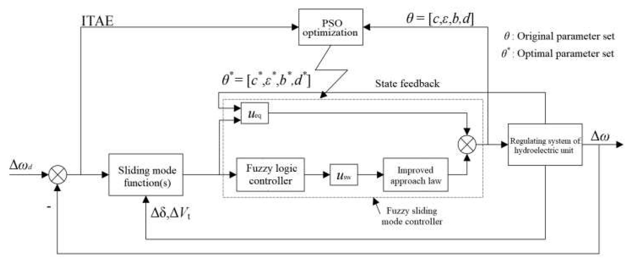
The main control parameters of the conventional PID controller,the conventional fuzzy sliding mode controller(FSMC) and the improved fuzzy sliding mode controller(nFSMCR) proposed in this paper are adjusted by using the PSO algorithm,the PSO parameters are set as follows:
The number of variables are respectively 3,2 and 4;Learning factor c 1 = c 2 =2;Population particle number k=100;The initial weight coefficient ω s t a r =0.9.
When the maximum number of iterations,the weight coefficient ω e n d =0.4,the speed V i is [-1,1],the maximum number of iterations G m a x =50,and the minimum adaptation value is 0.001.
The main optimization parameters and their value ranges are shown as follows:
PID: K p ∈[0,45], K i ∈[0,15], K d ∈[0,5];
FSMC: c∈[0,20], ε ∈[0,1];
nFSMCR: c∈[0,20], ε ∈[0,1],b∈[-1,1],d∈[-1,1].
Figure 3 shows the basic structure of nFSMCR control scheme for hydropower unit regulation system with PSO parameter optimization.
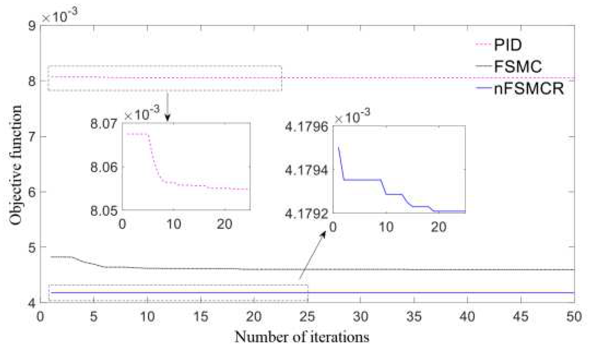
Under working condition 2,the PSO algorithm is used to optimize the parameters of each controller,and it is obtained that the system is disturbed by step power m g 0 =0.1p.u.The optimal control parameters under different controllers are as follows.
PID controller: K p =16, K i =0.13, K d =1.272;
FSMC: c=0.05, ε =0.0044;
nFSMCR: c=1.5806, ε =0.2304,b=0.014,d=0.1117, α =0.0015, σ =20,u=5.
The curve of the objective function was shown in Figure 4.

4.2. Simulation comparison

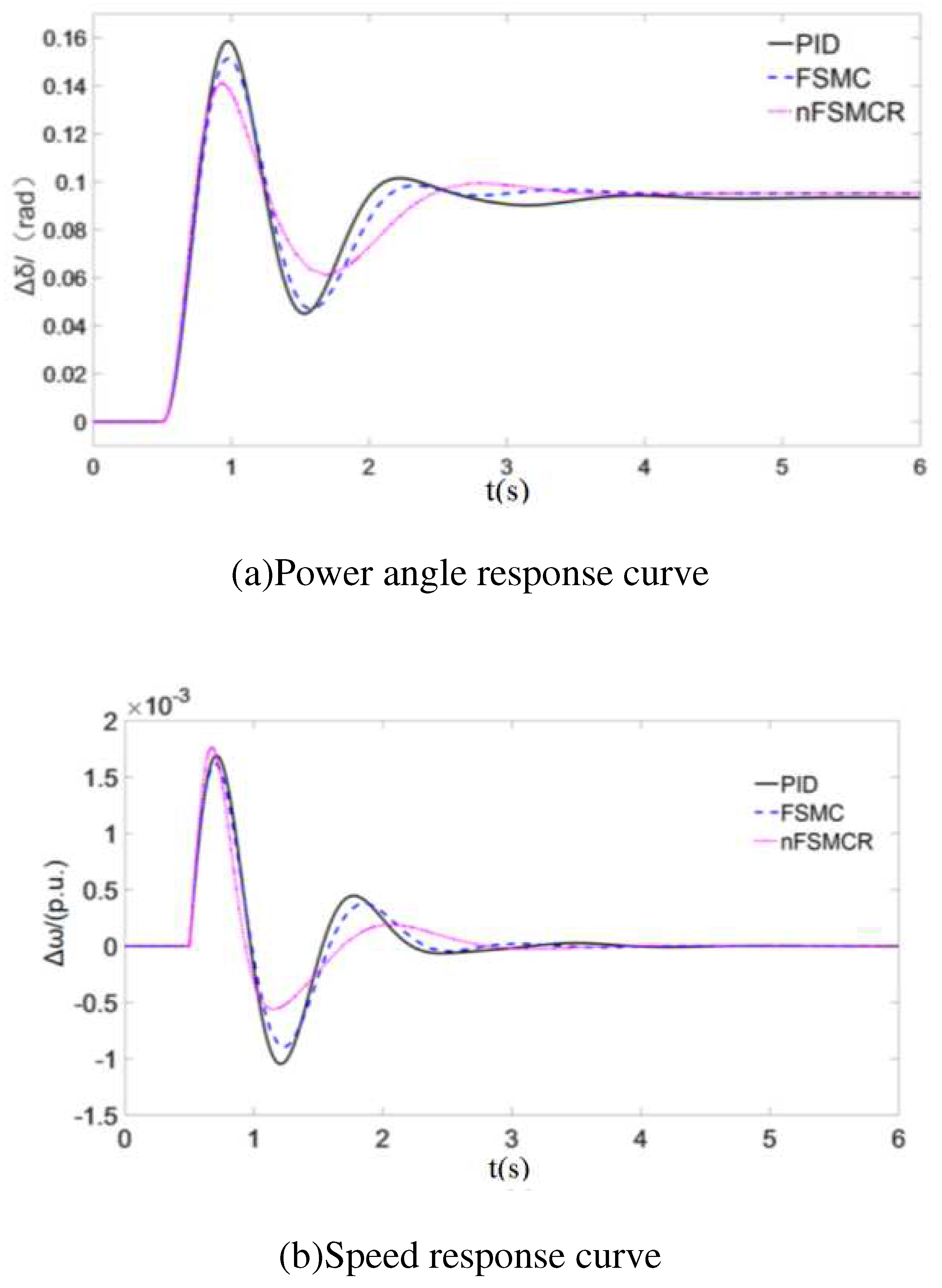
Under working condition 2,when the system power is disturbed by a step of m g 0 =0.1p.u.The optimal control curve under the action of different controllers is shown in Figure 5.
The power angle and frequency response curves of the system under the action of different controllers are shown in Figure 5.
The optimal control parameters under the action of different controllers are:
PID controller: K p =15.9, K i =0.12, K d =1.271;
FSMC: c=0.05, ε =0.005;
nFSMCR: c=1.581, ε =0.231,b=0.014,d=0.112, α =0.002, σ =20,u=5.
As can be seen from Figure 5, compared with PID controller and FSMC controller,nFSMCR controller can not only ensure faster stabilization time,but also minimize power angle overshoot.
The control performance of each controller was respectively verified under working conditions 1,3 and 4.The PID parameters optimized by PSO algorithm were respectively shown as follow:
Conditions 1: K p =5.33, K i =0.1, K d =1.97;
Conditions 2: K p =20, K i =1.22, K d =0.63;
Conditions 4: K p =32.85, K i =3.58, K d =1.19.
The parameter Settings of the FSMC controller and nFSMCR controller remain unchanged,then the external disturbances are all step disturbances with m g 0 =0.1p.u.
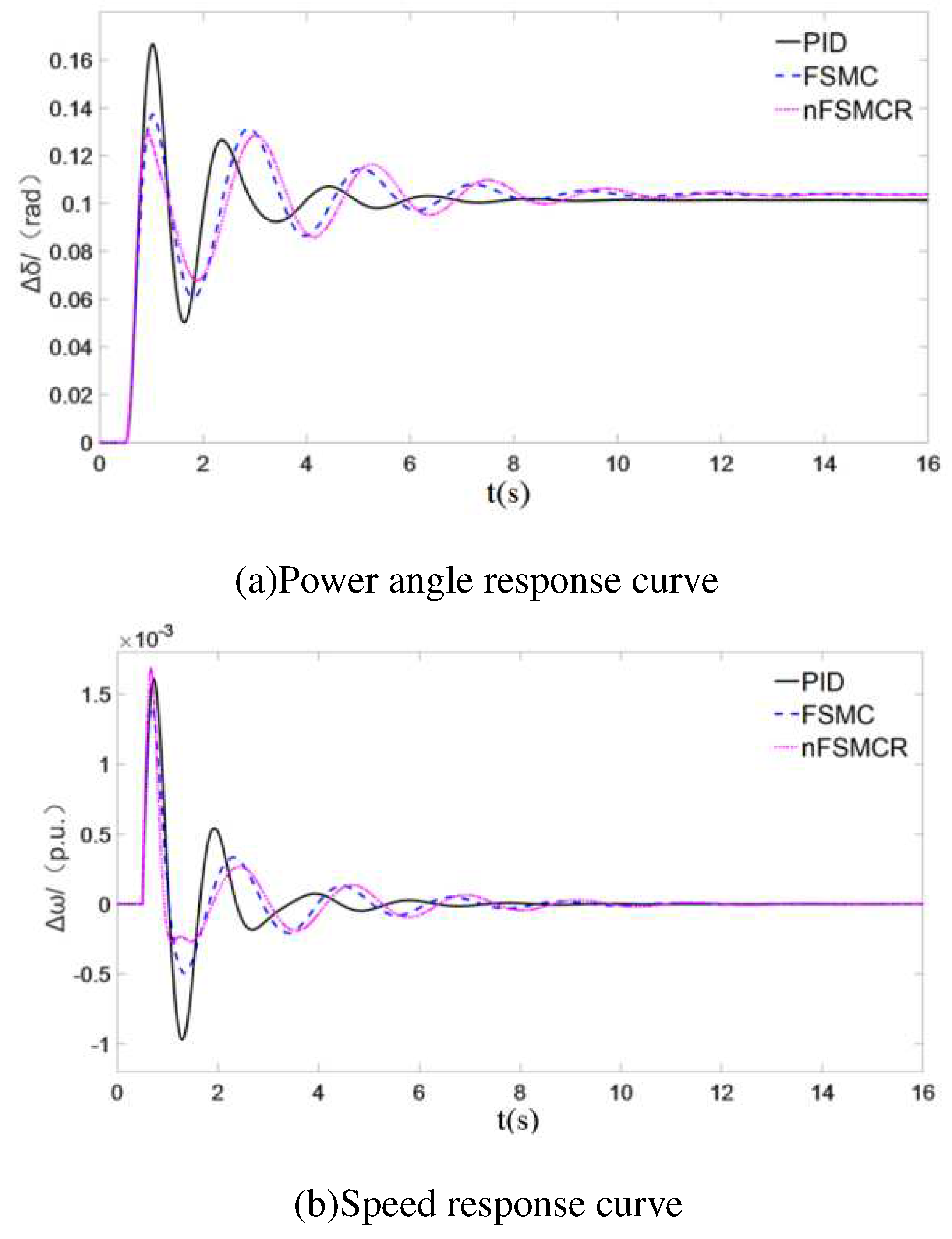
As shown in Figure 6, the PID controller has the shortest stabilization time but the largest power angle overshoot,the control effect of FSMC and nFSMCR controller is similar,among which the nFSMCR controller has the smallest power angle overshoot, but the stabilization time is longer,that is,the speed adjustment of nFSMCR controller is slightly insufficient under the condition of 30% rated load.
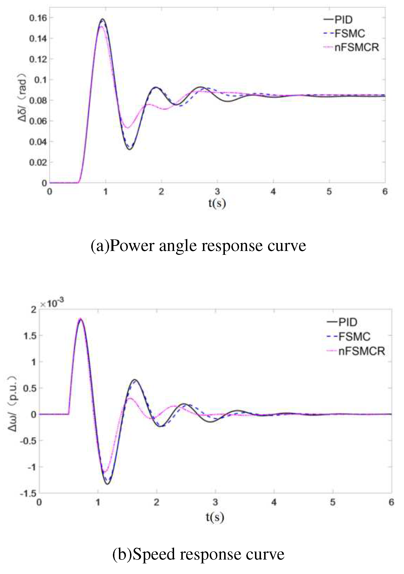
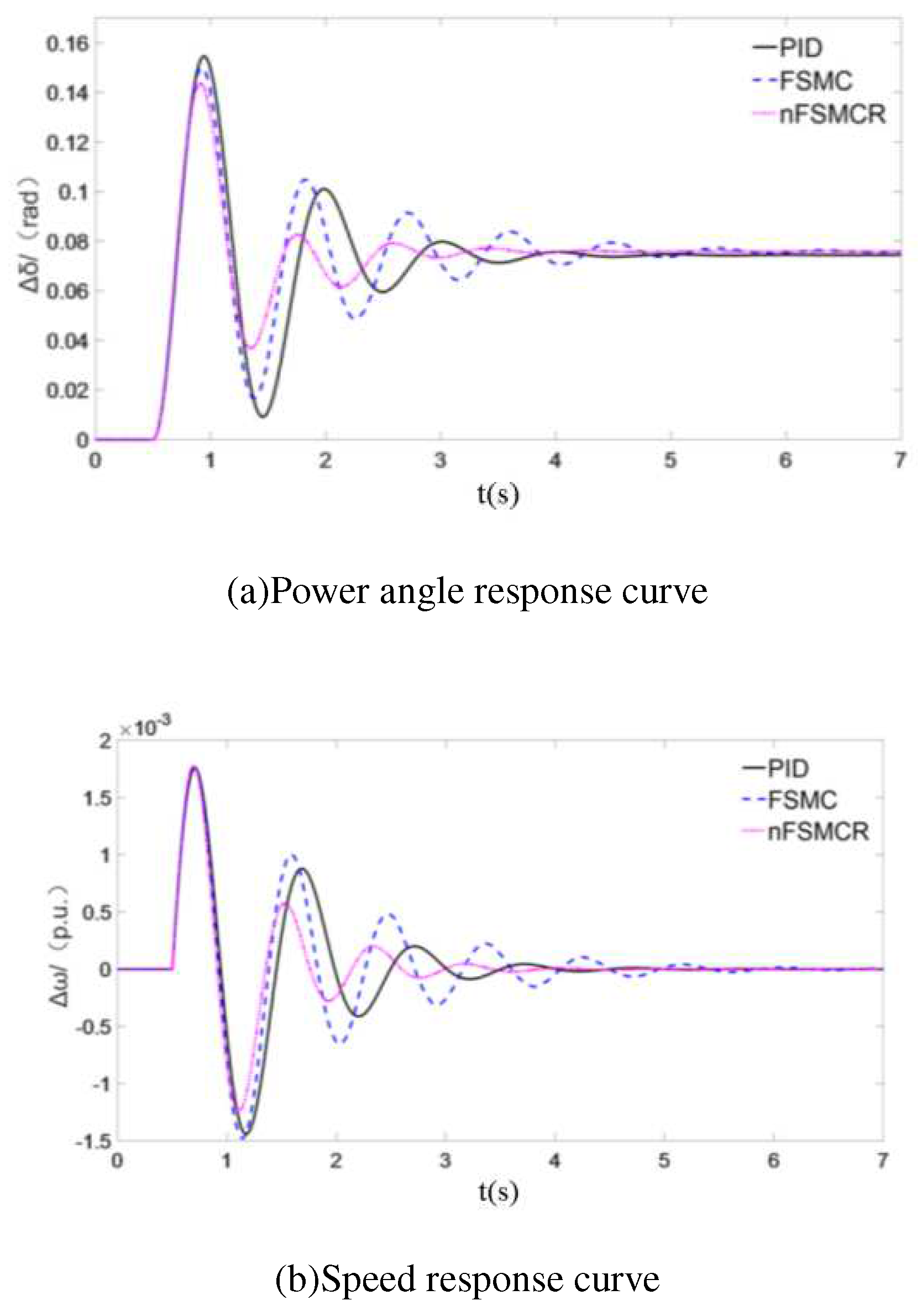
We can see the power angle response curves and frequency response curves of the system under in different working conditions were respectively shown in Figure 6, Figure 7 and Figure 8.
According to Figure 7, nFSMCR controller has better oscillation suppression effect than PID controller and FSMC controller.
As shown in Figure 8, nFSMCR has the shortest stabilization time (2.39s) and can stabilize the power Angle and frequency of the system with less fluctuation period,indicating that under working condition 4,the hydropower unit using nFSMCR controller has a better dynamic response process.
By comprehensive comparison of the control performance of each controller under different load conditions,it can be seen that although the stability time of the nFSMCR controller is the longest under 30% rated load,it ensures that the system power Angle will not overshoot too much.At 70% and 90% rated loads,nFSMCR controller shows certain advantages in speed and power angle oscillation suppression.
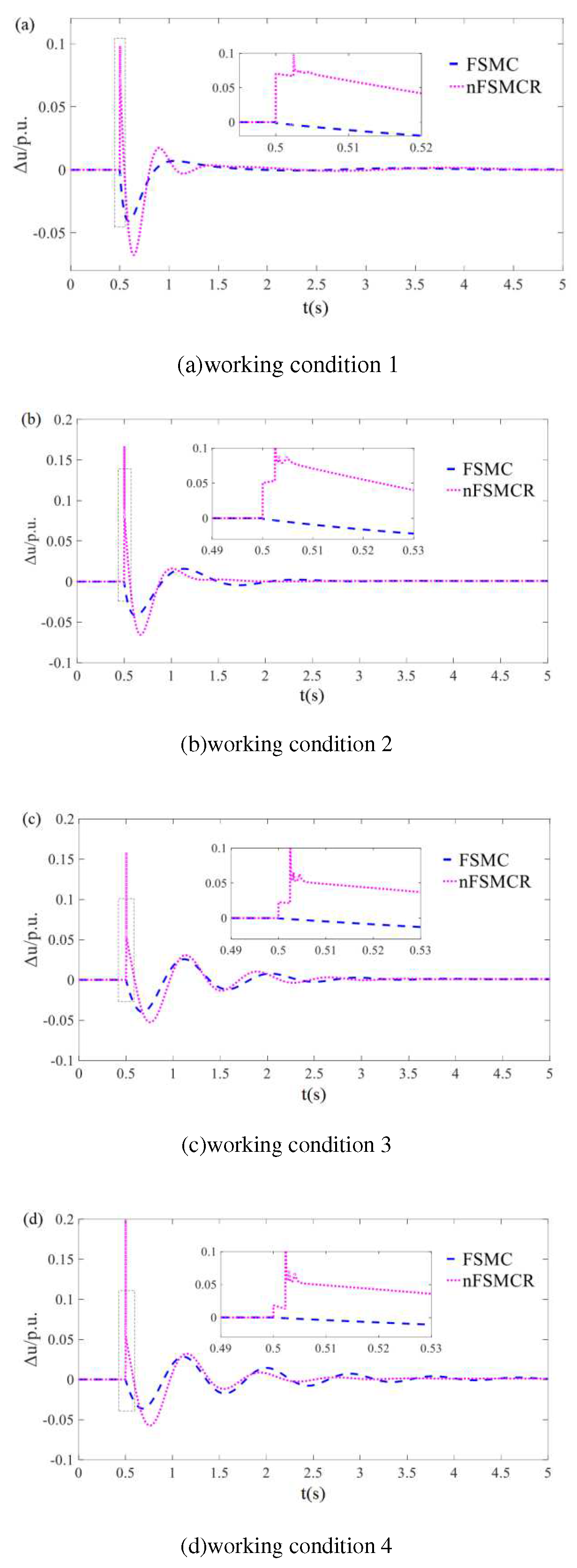
The output changes of FSMC controller and nFSMCR controller under different load conditions are compared,as shown in Figure 9.
The Sliding mode controller designed by combining sliding mode control theory and Fuzzy inference system can effectively improve the quality of controller regulation, reduce the occurrence probability of low-frequency oscillation,improve the control performance of the system, and enhance the adaptability of the controller.
Especially,we can see from Figure 9, the two fuzzy sliding mode controllers do not appear obvious chattering phenomenon under various working conditions.At the same time,it can also be seen from the figure that compared with the FSMC controller,the nFSMCR controller has a larger output at the initial stage of negative disturbance,and can quickly become stable at the later stage of disturbance,which means that compared with the FSMC controller,nFSMCR controller can provide better external disturbance suppression ability and better dynamic response process.
Based on the above simulation experiments and analysis and discussion,the advantages of nFSMCR controller compared with conventional PID and conventional fuzzy sliding mode controller can be summarized: when the system has power disturbance,nFSMCR controller can effectively reduce the overshoot of power Angle,improve the attenuation speed of system oscillation,and then suppress the possibility of low-frequency oscillation.
In order to solve the limitation of the regulation range of conventional reaching law and effectively improve the stability characteristics of HL240-LJ-140 hydraulic turbine under different load conditions, by dynamically adapting the variable speed reaching law of system output and operating point state, based on the premise of HTRS in working conditions 1, 2, 3 and 4.In addition,when the load conditions of the system change,even if the control parameters are not adjusted, the controller can also ensure a good control effect,with strong robustness.

5. CONCLUSIONS

Based on the stability characteristics of HTRS under different working conditions,combined with sliding mode control theory and fuzzy inference system,a suitable fuzzy sliding mode controller is designed.In order to improve the control quality of the controller and reduce the probability of low-frequency oscillation of the system,according to the characteristics of the established model and the actual operation requirements,the electrical characteristics are introduced into the sliding mode surface design,so that the controller can obtain more dynamic information of the system,optimize the regulation process,and improve the control performance of the system.At the same time,in order to solve the limitation of the regulation range of the conventional reaching law,a variable speed reaching law which can dynamically adapt to the output and operating point state of the system is designed to enhance the adaptive ability of the controller.The robustness of the proposed control strategy is verified by constructing Lyapunov function.Finally,under different load condition by simulation of the disturbance of power system,at the same time with conventional PID and control effect of the size paste sliding mode controller is compared,the results show that the designed controller has better angle overshoot and system oscillation suppression ability,and the change of working condition of the system has good adaptability,it has certain reference value to ensure the stable operation of hydropower units and restrain the low frequency oscillation of power system.

Author Contributions

Xiaoping Huang and Wenzhe Huang designed research,performed research.Qiu Lu analyzed data.All authors contributed to the writing and revisions.

Funding

This work was supported by Scientific Research and Technology Development Program of Guangxi(No.GuikeAA19254010).

Institutional Review Board Statement

The work was original research that has not been published previously, and not under consideration for publication elsewhere, in whole or in part.

Informed Consent Statement

It is approved by all authors for publication.

Data Availability Statement

All data generated or analysed during this study were included in this article.

Acknowledgments

The authors wish to express their gratitude.

Conflicts of Interest

The authors declare no competing interests.

Corresponding author

Correspondence to Xiaoping Huang.

NOMENCLATURE

H T R S Hydro-turbine regulating system.
F S M C Fuzzy sliding mode controller.
n F S M C Improved fuzzy sliding mode controller.
P I D Proportion Integration Differentiation.

References

  1. S.M.Mozayan,M.Saad,H.Vahedi,et al,“Sliding mode control of PMSG wind turbine based on enhanced exponential reaching law”,IEEE Transactions on Industrial Electronics,vol.63,no.10,pp.6148-6159,Oct.2016. [CrossRef]
  2. F.Blaabjerg,M.Liserre,K.Ma,“Power electronics converters for wind turbine systems”,IEEE Trans. Ind. Appl.,vol.48,no.2,pp.708-719,Oct.2012. [CrossRef]
  3. Weijia Yang,Per Norrlund,Chiyung Chung, et al,“Eigen-analysis of hydraulic-mechanical-electrical coupling mechanism for small signal stability of hydro-power plant”,Renewable Energy,vol.115,pp.1014-1025,Jan.2017. [CrossRef]
  4. Xiaoping Huang,Yufang Zhu,Paniz Vafaei,et al,“An iterative simulation algorithm for large oscillation of the applicable 2D-electrical system on a complex nonlinear substrate”,Engineering with Computers,vol.38,pp.3137–3149,Feb.2021. [CrossRef]
  5. Diyi Chen,Cong Ding,Younghae Do,et al,“Nonlinear dynamic analysis for a Francis hydro-turbine governing system and its control”,Journal of the Franklin Institute,vol.351,no.9,pp.4596-4618,Sep.2014. [CrossRef]
  6. P.C.O.Silva,C.Nicolet,P.Grillot,et al,“Assessment of power swings in hydropower plants through high-order modeling and eigenanalysis”,IEEE Transactions on Industry Applications,vol.53,no.4,pp.3345-3354,Nov.2017. [CrossRef]
  7. Xiaoping Huang,Huadong Hao, Khaled Oslub,et al,“Dynamic stability/instability simulation of the rotary size-dependent functionally graded microsystem”,Engineering with Computers,May 2021. [CrossRef]
  8. J.I.Sarasua,J.I.Perez-Diaz,J.R.Wilhelmi,et al,“Dynamic response and governor tuning of a long penstock pumped-storage hydropower plant equipped with a pump-turbine and a doubly fed induction generator”,Energy Conversion and Management,vol.106,pp.151-164,Dec.2015. [CrossRef]
  9. Chaoshun.Li,Nan Zhang,Xinjie Lai,et al,“Design of a fractional-order PID controller for a pumped storage unit using a gravitational search algorithm based on the Cauchy and Gaussian mutation”,Information Sciences,396:162-181,Aug.2017. [CrossRef]
  10. Yang Zheng,Jianzhong Zhou,Wenlong Zhu, et al,“Design of a multi-mode intelligent model predictive control strategy for hydroelectric generating unit”,Neurocomputing,207:287-299,Sep.2016. [CrossRef]
  11. H.V.Pico,J.D.Mccalley,A.Angel,et al,“Analysis of very low frequency oscillations in hydro-dominant power systems using multi-unit modelingt”,IEEE Trans. Power Syst.,vol.27,no.4,pp.1906-1915,Nov.2012. [CrossRef]
  12. Beibei Xu,Feifei Wang,Diyi Chen,et al,“Hamiltonian modeling of multi-hydro-turbine governing systems with sharing common penstock and dynamic analyses under shock load”,Energy Conversion and Management,vol.108,no.15,pp.478-487,Jan.2016. [CrossRef]
  13. Bin Wang,Jianyi Xue,Fengjiao Wu,et al,“Robust Takagi-Sugeno fuzzy control for fractional order hydro-turbine governing system”,ISA Transactions,65:72-80,Nov.2016. [CrossRef]
  14. Chang Xu,Dianwei Qian,“Governor design for a hydropower plant with an upstream surge tank by GA-based fuzzy reduced-order sliding mode”,Energies,vol.8,no.12,pp.13442-13457,2015. [CrossRef]
  15. Lei Chen,Xiaomin Lu,Yong Min,et al,“Optimization of governor parameters to prevent frequency oscillations in power systems”,IEEE Transactions on Power Systems,vol.33,no.4,pp.4466-4474,Jul.2018. [CrossRef]
  16. Hao Zhang,Diyi Chen,Beibei Xu,et al,“Nonlinear modeling and dynamic analysis of hydro-turbine governing system in the process of load rejection transient”,Energy Conversion and Management,90:128-137,Jan.2015. [CrossRef]
  17. Huanhuan Li,Diyi Chen,Hao Zhang,et al,“Nonlinear modeling and dynamic analysis of a hydro-turbine governing system in the process of sudden load increase transient”,Mechanical Systems and Signal Processing,80:414-428,Dec.2016. [CrossRef]
  18. J.Shin,D.Kwak,K.Kwak,“Model predictive path planning for an autonomous ground vehicle in rough terrain,”International Journal of Control,Automation, and Systems,vol.19,no.6,pp.2224–2237,2021. [CrossRef]
  19. Chaoshun Li,Yifeng Mao,Jiandong Yang,et al,“A nonlinear generalized predictive control for pumped storage unit”,Renewable Energy,114:945-959,2017. [CrossRef]
  20. Weijia Yang,Per Norrlund,Johan Bladh,et al,“Hydraulic damping mechanism of low frequency oscillations in power systems: Quantitative analysis using a nonlinear model of hydropower plants”,Applied Energy,212:1138-1152,Feb.2018. [CrossRef]
  21. G.Delille,B.Francois,G.Malarange, “Dynamic frequency control support by energy storage to reduce the impact of wind and solar generation on isolated power system’s inertia”,IEEE Trans.Sustain.Energy,vol.3,no.4,pp.931-939,Oct.2012. [CrossRef]
  22. C.G.Jiang,J.H.Zhou,S Peng,et al,“Ultra-low frequency oscillation analysis and robust fixed order control design”,International Journal of Electrical Power and Energy Systems,104:269-278,Jan.2019. [CrossRef]
  23. Bicheng Guo,Jiang Guo.“Feedback linearization and reaching law based sliding mode control design for nonlinear hydraulic turbine governing system”,Energies,vol.12,no.12,pp.1-19,Jun.2019. [CrossRef]
  24. Xiaohui Yuan,Zhihuan Chen,Yanbin Yuan,et al,“Design of fuzzy sliding mode controller for hydraulic turbine regulating system via input state feedback linearization method”,Energy,vol.91.no.1,pp.173-187,Dec.2015. [CrossRef]
  25. Yinggan Tang,Xiangyang Zhang,Dongli Zhang,et al,“Fractional order sliding mode controller design for antilock braking systems”,Neurocomputing,111:122-130,Jul.2016. [CrossRef]
  26. Zhiren Han,Chuang Wei,Simin Du, Zhen Jia,Xinyang Du,“Numerical simulation and experimental research on rubber flexible-die forming limitation with new position-limited backpressure mechanism”,The International Journal of Advanced Manufacturing Technology,vol.116,pp.2183–2196,Jul.2021. [CrossRef]
  27. N.Pathak,T.S.Bhatti,A.Verma,“Discrete data AGC of hydro-thermal systems under varying turbine time constants along with the power system loading conditions”,IEEE Trans. Ind. Appl.,vol.53,no.5,pp.4998-5013,Sep.2017. [CrossRef]
  28. A.Salem,H.Van Khang,K.G.Robbersmyr,et al,“Voltage source multilevel inverters with reduced device count:Topological review and novel comparative factors”,IEEE Trans.Power Electron.,vol.36,no.3,pp.2720-2747,Mar.2021. [CrossRef]
  29. Civalek Ö,Demir C,“A simple mathematical model of microtubules surrounded by an elastic matrix by nonlocal fnite element method”,Appl. Math Comput.,289:335-352,2016. [CrossRef]
  30. Z.Akhtar,B.Chaudhuri,S.Y.Ron Hui,“Primary frequency control contribution from smart loads using reactive compensation”,IEEE Trans.Smart Grid,vol.6,no.5,pp.2356-2365,Sep.2015. [CrossRef]
  31. D.Rimorov,I.Kamwa,G.Joos,“Quasi-steady-state approach for analysis of frequency oscillations and damping controller design”,IEEE Trans. Power Syst.,vol.31,no.4,pp.3212-3220,Jul.2016. [CrossRef]
  32. Xinjie Lai,Chaoshun Li,Wencheng Guo,et al,“Stability and dynamic characteristics of the nonlinear coupling system of hydropower station and power grid”,Communications in Nonlinear Science and Numerical Simulation,79:104919.1-104919.20,Dec.2019. [CrossRef]
  33. M.A.Fnaiech,F.Betin,G.A.Capolino,et al,“Fuzzy logic and sliding-mode controls applied to six-phase induction machine with open phases”,IEEE Trans.Ind.Electron.,vol.57,no.1,pp.354-364,Jan.2010. [CrossRef]
  34. A.Moeini,I.Kamwa,“Analytical concepts for reactive power based primary frequency control in power systems”,IEEE Trans.Power Syst.,vol.31,no.6,pp.4217-4230,Nov.2016. [CrossRef]
  35. Xiaoguang Zhang,Lizhi Sun,Ke Zhao,et al,“Nonlinear speed control for PMSM system using sliding-mode control and disturbance compensation techniques”,IEEE Transactions on Power Electronics,vol.28,no.3,pp.1358-1365,Mar.2013. [CrossRef]
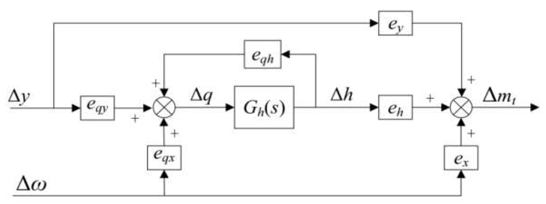
Figure 1. Linearized internal characteristic model of hydraulic turbine.
Preprints 69846 g001
Figure 2. Single machine infinite bus Phillips-Heffron linearization model.
Preprints 69846 g002
Figure 3. The structure diagram of nFSMCR controller assisted with HICA algorithm for HTRS.
Preprints 69846 g003
Figure 4. The structure diagram of nFSMCR controller assisted with HICA algorithm for HTRS.
Preprints 69846 g004
Figure 5. Comparison of the control performance of different controllers under working condition 2.
Preprints 69846 g005
Figure 6. Comparison of the control performance of different controllers under working condition 1.
Preprints 69846 g006
Figure 7. Comparison of the control performance of different controllers under working condition 3.
Preprints 69846 g007
Figure 8. Comparison of the control performance of different controllers under working condition 4.
Preprints 69846 g008
Figure 9. Controller output comparison.
Preprints 69846 g009
Table 1. Linearized internal characteristic model of hydraulic turbine.
Preprints 69846 i001
Table 2. Parameters of hydroturbine model under rated water head and different operation conditions.
Preprints 69846 i002
Table 3. Parameters of generator model under different operation conditions.
Preprints 69846 i003
Disclaimer/Publisher’s Note: The statements, opinions and data contained in all publications are solely those of the individual author(s) and contributor(s) and not of MDPI and/or the editor(s). MDPI and/or the editor(s) disclaim responsibility for any injury to people or property resulting from any ideas, methods, instructions or products referred to in the content.
Copyright: This open access article is published under a Creative Commons CC BY 4.0 license, which permit the free download, distribution, and reuse, provided that the author and preprint are cited in any reuse.
Prerpints.org logo

Preprints.org is a free preprint server supported by MDPI in Basel, Switzerland.

Subscribe

© 2024 MDPI (Basel, Switzerland) unless otherwise stated