1. Introduction
By studying the tractor seat suspension with good vibration reduction performance and controlling the seat suspension through scientific and effective control algorithms, it can effectively reduce the vibration transmitted from the road surface to the human body and reduce the impact of vibration on human health. Tractors usually work and drive in fields with large road excitation, so that tractor drivers are exposed to various vibration levels. Long-term vibration will cause serious damage to the driver 's body [1,2]. Therefore, the safety and comfort of tractor drivers has become a key research field in the design and development of tractors. Factors such as road roughness, tires, seat suspension systems, and full-body vibration affect the driver 's ride comfort [3]. How to effectively improve the ride comfort of tractors without increasing input costs is one of the key issues for agricultural machinery companies to compete for solutions. Therefore, it is particularly important to improve the ride comfort and driving stability of tractors. Different suspension systems are adopted for tractors of different sizes to meet the diversified vibration reduction requirements. The vibration generated by the tractor during driving and working is finally transmitted to the human body through the seat suspension, and the seat suspension can minimize the vibration impact transmitted to the human body [4]. The seat structure and parameters are easy to adjust. It has the advantages of short manufacturing cycle, quick effect, practical economy, convenience and feasibility, and does not affect the other performance of the vehicle when changing the dynamic characteristics of the system. In short, it is more practical and economical to study the tractor seat suspension system to improve its vibration isolation performance [5].
The seat suspension system generally includes elastic elements, dampers and upper and lower frames. According to different control forms, the seat suspension system can be divided into three categories: passive seat suspension, semi-active seat suspension and active seat suspension. Compared with the passive seat suspension, the active seat suspension system has an active actuator. The active suspension system can be used in agricultural machinery to minimize the interference caused by uneven ground. The active seat suspension system applies external force through the actuator, thereby attenuating most of the vibration transmitted by the road surface, so that the suspension system is always in the best vibration reduction state.
Compared with the passive seat suspension system, the structure and control of the active seat suspension system are more complex, and the actuator outputs the active power completely according to the requirements of the control strategy. Therefore, it is the key to choose a scientific and effective control strategy to improve the performance of the tractor seat suspension. At present, the control strategies for active seat suspension include traditional PID control, linear quadratic regulator (LQR), fuzzy logic controller (FLC), artificial neural network (ANN), H∞ and sliding mode controller (SMC) [6]. In addition, many researchers have also designed hybrid controllers such as PID-FLC and SMC-PI. The H∞ optimal controller based on sliding mode observer designed by Xiaolong Wang et al. [7] can accurately estimate the unknown disturbance of the seat suspension system, and improve the performance index of the seat suspension and the driver 's ride comfort. Sha Shujing et al. [8] used the adaptive learning function of BP neural network to integrate the control parameters of the traditional PID seat suspension in real time by collecting the deviation signal, so that the seat suspension has better adaptability and damping effect. Ma shuo et al. [9] studied a PID control method of active seat suspension system based on low-pass filtering, which effectively improved the performance index of active seat suspension system. Luan Guangrui et al. [10] proposed a VEI-VD device and a semi-active control strategy. In the random excitation test, the root mean square value of the seat acceleration is effectively reduced and the ride comfort is improved. Munyaneza Olivier et al. [11] used the Skyhook controller to control the current supply of the hybrid magnetorheological damper and enhance the damping force under low current power supply. The skyhook controller improves seat comfort compared to uncontrolled conditions. Phu Do Xuan et al. [12] proposed a new switch adaptive fuzzy controller and applied it to the vibration control of automobile seat suspension with semi-active magnetorheological dampers. The automobile seat suspension with controllable magnetorheological dampers was used to verify the robustness and effectiveness of the proposed controller in the corresponding road excitation and external disturbance. The results show that the controller has better vibration control performance than the existing robust controller, and the displacement and speed at the seat position are well reduced. In general, the main purpose of seat suspension research is to design a controller with simple structure and good robustness to reduce vehicle vibration and achieve ride comfort.
MPC has become a very successful and mature control scheme in the past few decades and has been widely used in various fields [13]. Narayan, Jayesh [14] studied LQR and MPC control strategies, and the quadratic cost function of the two control schemes optimized the state variables and input variables, and used MATLAB-SIMULINK to simulate and compare the ride comfort index and actuator power. The results show that the suspension performance and power requirements of MPC are significantly improved compared with LQR on both road grades. MPC reduces the actuator power consumption requirements, actuator size and weight. I. Maciejewski et al. [26] designed a controller with adaptive mass identification function. The adaptive mechanism identifies the actual load mass to improve the vibration isolation effect and enhance the robustness of the system when the mass load response changes. Papadimitrakis Myron et al. [27] proposed a road preview model predictive controller combined with radial basis function model as the control scheme of the whole vehicle active suspension system. The RBF model adopted can effectively approximate the nonlinear behavior of the suspension system, thus improving the performance of the linear MPC method. In the impulse and ramp collision tests, the vertical acceleration of the vehicle body is reduced and the ride comfort is improved. Huang Kun et al. [15] considered the physical constraints of the electromagnetic actuator and the dynamic deflection stroke of the suspension. Based on the model predictive control method, a 1/4 vehicle electromagnetic active suspension controller was designed, and the instantaneous vertical impact and random uneven road conditions were simulated and analyzed. The results show that compared with the LQR active suspension, the model predictive control can improve the ride comfort performance of the vehicle. Zhao Qiang [16] designed a model predictive controller for the active suspension driven by electro-hydraulic servo. The simulation results show that the vertical acceleration of the body, the dynamic deflection of the suspension and the dynamic load of the tire are greatly reduced, and the damping effect is obvious. The model predictive controller has strong robustness under parameter changes and road disturbances. Model predictive control (MPC) is a control scheme that can directly adapt to the nonlinearity of the object, and has excellent dynamic response capability and small energy consumption, which is suitable for active seat suspension.
Aiming at the problem that the current passive seat suspension matching the tractor can not cope with the complex vibration environment in the field and can not achieve the best vibration reduction effect, this paper combines the new electromagnetic actuator technology and the seat suspension control method to establish the MPC active seat suspension model without increasing the input cost. When the tractor is driving under various working conditions, operating at different speeds and responding to changing load mass, the MPC controller controls the actuator to generate appropriate force to provide the best vibration reduction effect and improve the tractor. The vibration generated under driving and complex operating conditions affects driving stability and driver ride comfort.
2. Establishment of Tractor Active Seat Suspension System Model
Establishing a suitable tractor seat system model is the premise of studying the active seat suspension control, and analyzing the dynamic characteristics of the active seat suspension is a necessary link to verify the vibration reduction effect of the seat suspension. Therefore, it is necessary to analyze the system dynamics of the tractor scissor seat system and establish a 3-degree of freedom 1/4 vehicle active seat suspension mathematical model.
2.1. Dynamics Analysis of Seat Suspension System
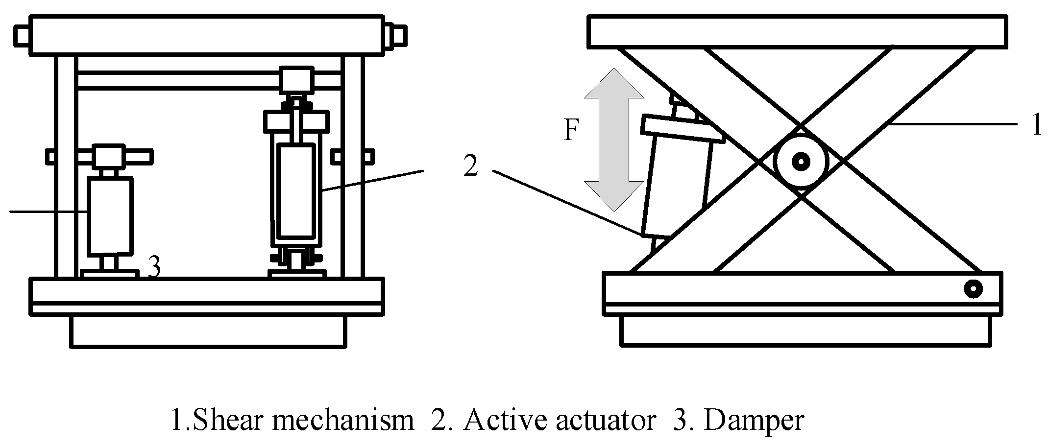
In this paper, the dynamics analysis of the widely used scissors seat structure is carried out, and the structure is X-shaped. Actuators can be divided into three categories: hydraulic, pneumatic and servo actuators [17]. As shown in
Figure 1, the seat base is fixed on the vehicle cockpit floor, and the roof is connected to the seat chassis. The active actuator is placed in the inner shear structure, and the upper and lower ends of the active actuator are connected to the upper and lower plates of the seat base. The active seat suspension system with scissor mechanism is driven by an active actuator in the vertical direction, and the active actuator is used in parallel with the damper to absorb and reduce the vibration impact in the vertical direction [19].
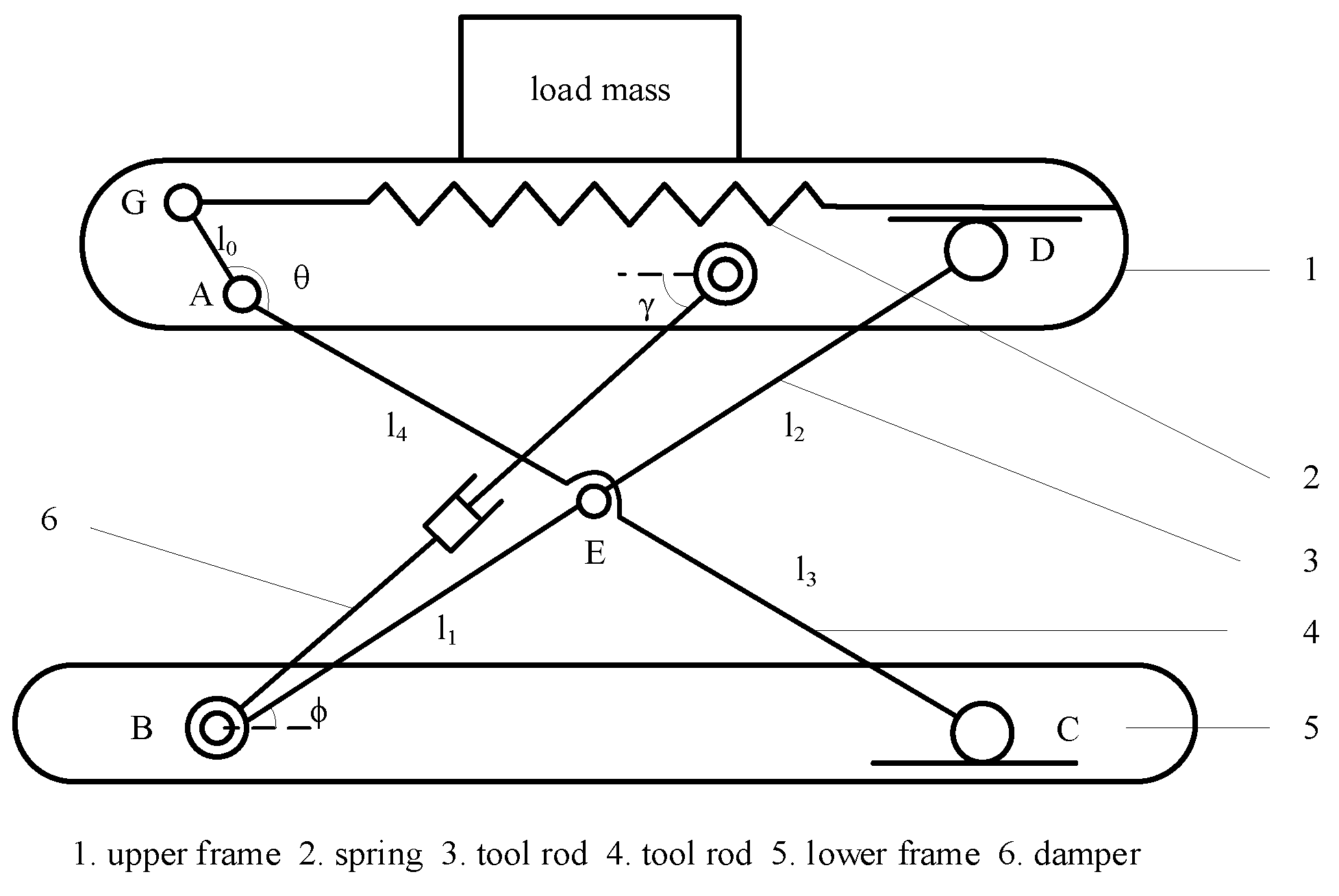
The schematic diagram of the tractor scissor seat suspension structure is shown in
Figure 2, which is composed of scissors, upper and lower frames, springs, shock absorbers and other components. Interconnection point E connects the seat suspension shear rod. The shear bar 3 is hinged with the lower frame of the seat at point B, and the upper point D can slide into the linear groove of the upper frame. The shear bar 4 is hinged with the upper frame of the seat at point A, and its lower end C can slide into the linear groove of the lower frame of the seat. Spring 2 is a linear coil spring with a stiffness of k. Spring 2 is placed horizontally in the upper frame of the seat. One end of the spring 2 is connected to the shear bar 4 at point G, and the other end is connected to the right side of the seat suspension upper frame. Damper 6 is located between the upper and lower frames of the seat suspension, and the damping coefficient is c.
The following assumptions are made before the dynamic analysis of the scissor-type front seat suspension system: (1) Without considering the influence of the seat upper plate cushion in contact with the human body, the bearing mass is 75 % of the total mass of the human body and the seat suspension upper plate. (2) Assume that the seat scissors have no mass. (3) Under the external excitation, the seat vibrates in the static equilibrium position.
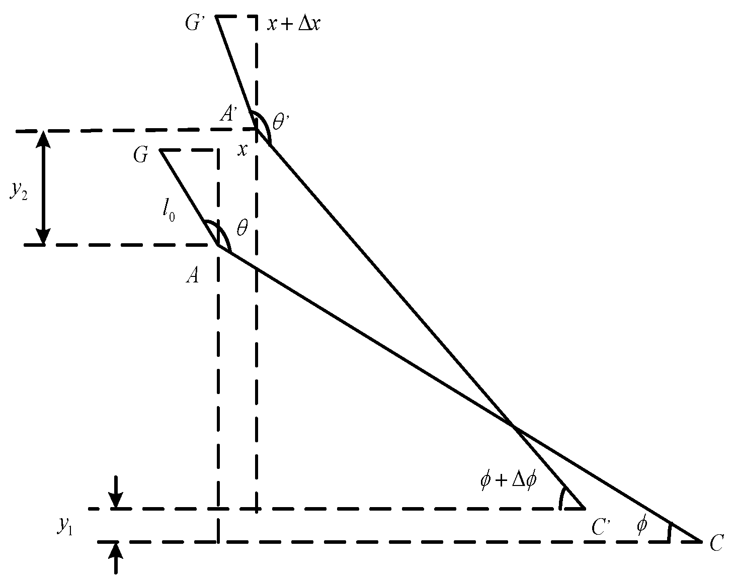
The scissors movement of the seat suspension under external excitation is shown in
Figure 3.
At this time, the spring deformation under external excitation is:
Where
is the excitation amplitude,
is the excitation frequency,
is the spring deformation.
The inertia force acting on the upper plate of the seat suspension by the vibration generated by the external excitation is, and the equilibrium equation can be established:
Where
is damping force,
is the angle between the axial direction of the damper and the upper plate at the static equilibrium position,
is the change of the inclination angle of the damper,
is the sliding friction factor,
is spring force.
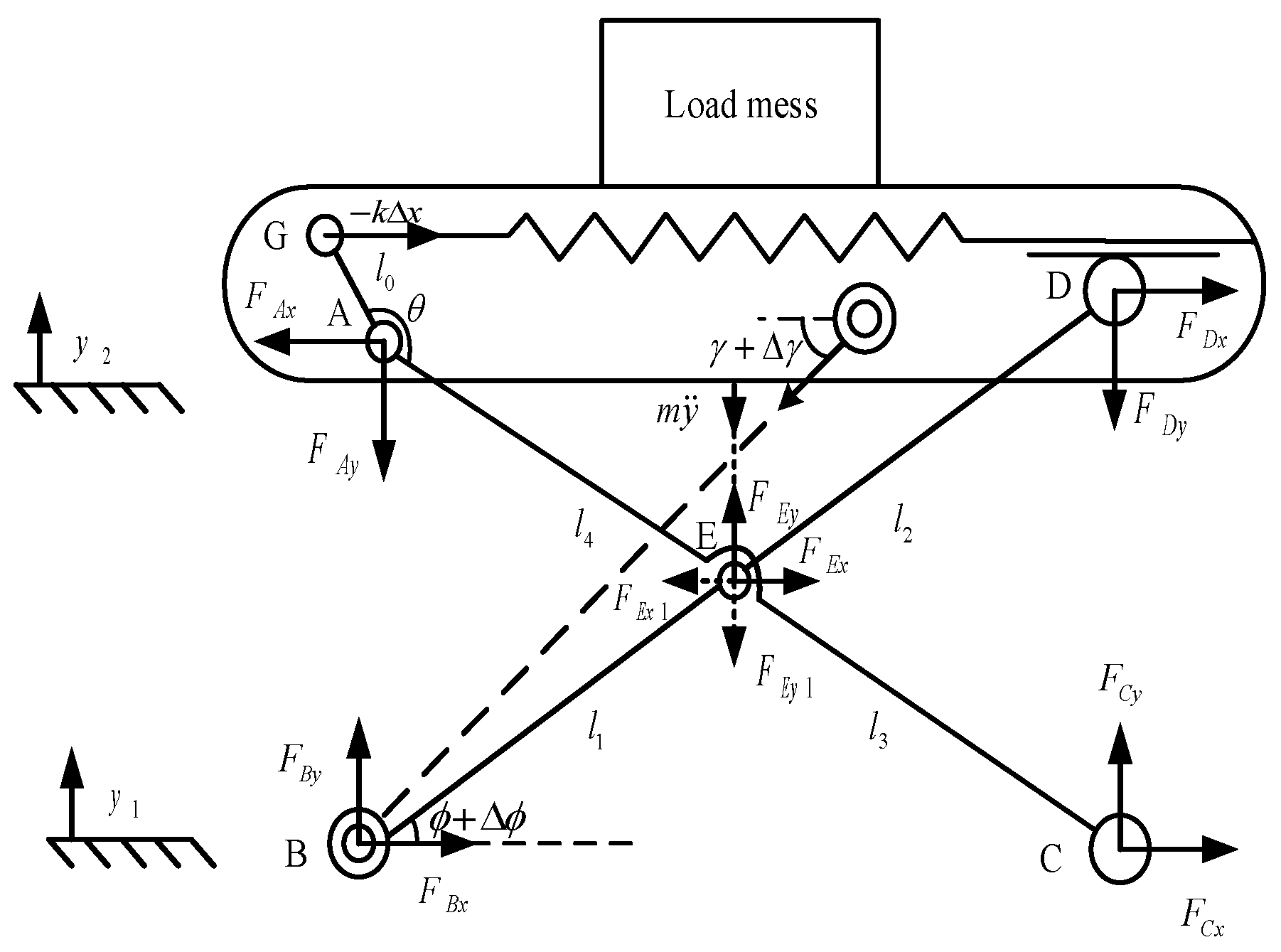
Figure 4.
Overall force analysis of seat.
Figure 4.
Overall force analysis of seat.
Through the force analysis of the shear rod, the equilibrium equations of AC and BD shear rods are established respectively:
When
, the following equation can be obtained:
2.2. Mathematical Model of Active Seat Suspension System
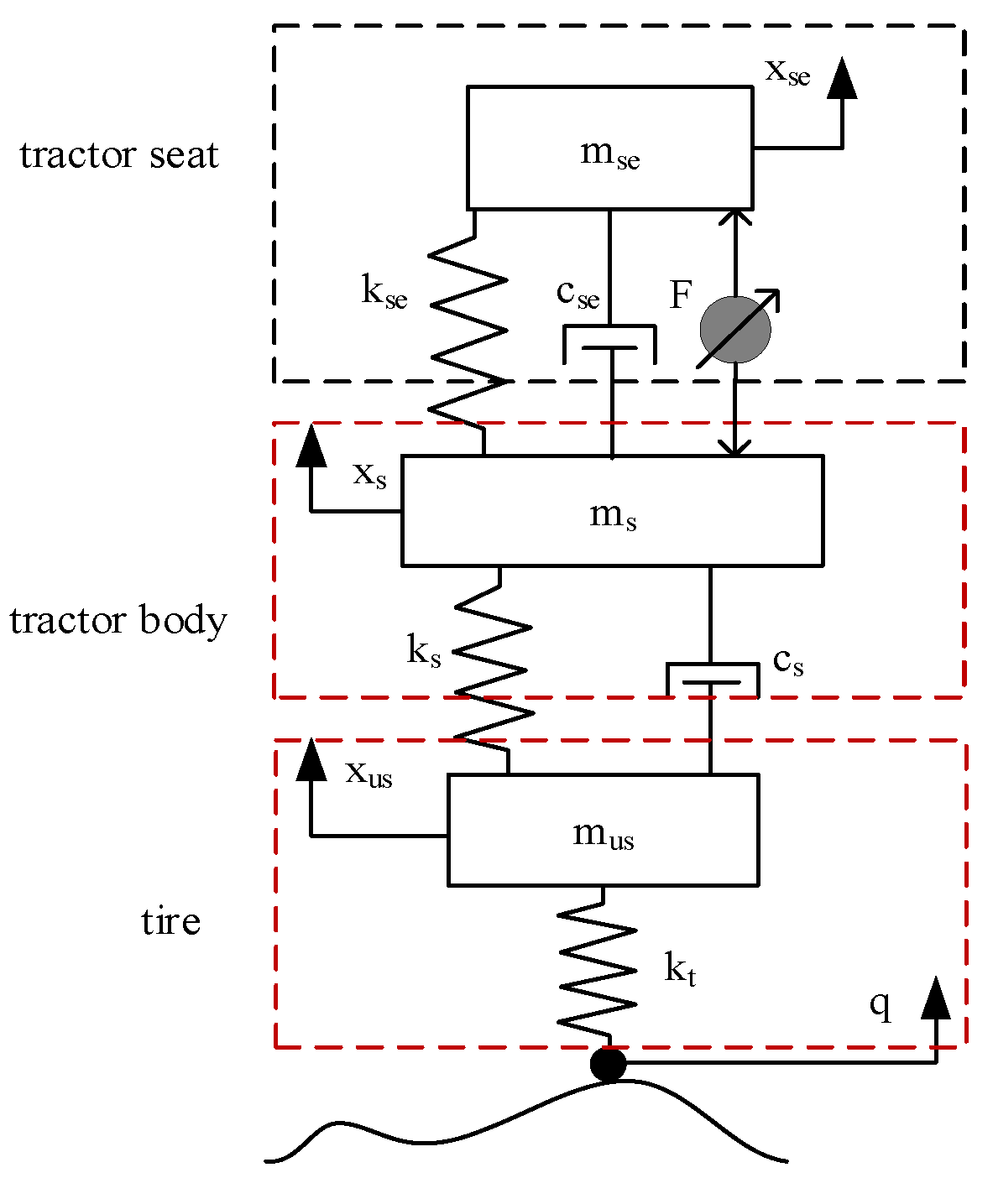
The seat suspension model is the basis for the design of the active seat suspension controller. In engineering applications, a simplified system model is usually used to describe the controlled object [20]. This paper mainly studies the vibration of the tractor seat suspension in the vertical direction. Combined with the dynamic modeling theory, for the convenience of research, this paper simplifies the tractor into a 1/4 vehicle model with three degrees of freedom. The model has been widely used in seat suspension control [21,22]. The tractor seat and the human body as a whole are assumed to be a single-degree-of-freedom system.
Figure 5 shows the active seat suspension that integrates a 1/4 vehicle model and an active actuator fixed in parallel with the suspension.
Since the tire damping can be ignored, the tire is simplified as a constant coefficient stiffness spring. Assuming that both the seat suspension and the vehicle suspension have linear characteristics, the dynamic equation is:
where
is the combined mass of human and seat,
is the body mass,
is the unsprung mass. Their displacements in the vertical direction are
and
,
is random road excitation displacement,
is the seat suspension spring stiffness coefficient and damping coefficient,
is the stiffness coefficient and damping coefficient of the tractor body,
is active control.
The active control force and road excitation of the seat suspension are taken as the control vector. The body-seat displacement, body-seat vertical vibration velocity, body displacement, body vertical vibration velocity, unsprung mass displacement and unsprung mass vertical vibration velocity are the state variables of the system. The human-seat displacement, human-seat vertical vibration velocity, body displacement, body vertical vibration velocity, human-seat vertical vibration acceleration, and seat suspension dynamic deflection are output variable.
Then the state space equation of the system model corresponding to Equation 8 can be expressed as:
Where
is the coefficient matrix of state vector,
is the input coefficient matrix,
is the output coefficient matrix of the state vector,
is the output coefficient matrix,
is the input vector.
2.3. Mathematical Model of Active Seat Suspension Actuator
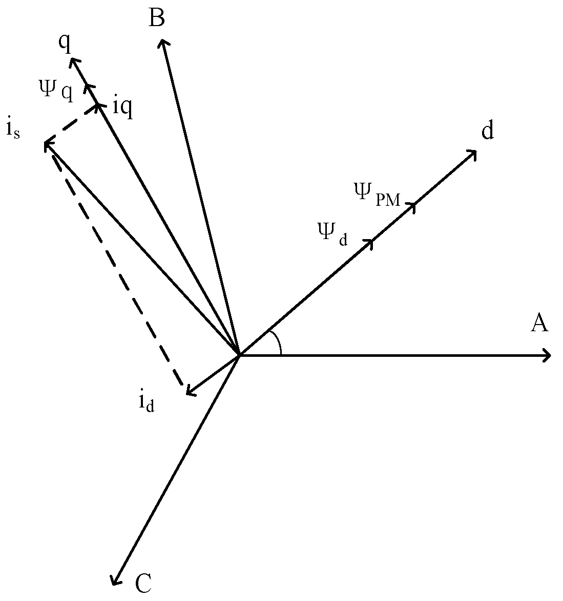
The permanent magnet synchronous linear motor has great advantages as an active seat suspension actuator. It has simple and compact structure, high conversion efficiency, high control accuracy, small error and short response time. Compared with the traditional motor, it can directly complete the linear motion [23]. In this paper, the ideal active force required by the permanent magnet synchronous linear motor output active seat suspension system is taken as the precondition to realize the control effect of the tractor active seat suspension, and the control system of the linear actuator itself is not studied. Assuming that the winding is ideally distributed, the permanent magnet magnetic field is stable, and the harmonic and magnetic saturation effects are not considered, and the end effect of the linear motor is ignored. The control principle model of the linear motor actuator is established, and the space vector diagram of the actuator is shown in
Figure 6.
The voltage equation of linear motor in
coordinate is:
Where
is the linear motor phase resistance,
is the flux linkage component of the motor permanent magnet in the
three-phase.
The
phase coordinate equation of the linear motor is transformed into the
axis coordinate, and the voltage balance equation in the
phase coordinate is:
Where
is the stator voltage under the direct and quadrature axes,
is the stator current under the direct and quadrature axes,
is the inductance under the direct and quadrature axes,
is the flux component of the permanent magnet under the direct and quadrature axes ,
is the permanent magnet flux linkage.
is the mover speed of linear motor,
is polar distance.
The control
-axis current
is set to 0, and the linear function relationship between the output thrust of the linear motor actuator and the quadrature-axis current can be obtained. The electromagnetic thrust of the linear motor is expressed as:
Where
is the electromagnetic thrust coefficient of the motor.
The linear motor model is established by the above equations. The input of the motor model is three-phase current. After Clark transformation and Park transformation, the current of the axis under the two-phase rotating shaft system is obtained. According to equations (10) to (13), the active force required for the active seat is obtained. The linear actuator outputs the ideal active force according to the upper MPC controller, which directly acts on the seat suspension system.
3. Model Predictive Controller Design for Active Seat Suspension
The basic idea of model predictive control is to predict the future output of the system by using the existing model, the current state of the system and the future control volume area, and to achieve the control goal by rollingly solving the constrained optimization problem. Predictive control solves the optimization problem within the moving time range. Long predictive ability is the most important feature of MPC different from other control methods.
The three key points of MPC are system model, system constraints, and defining weights [24,25].
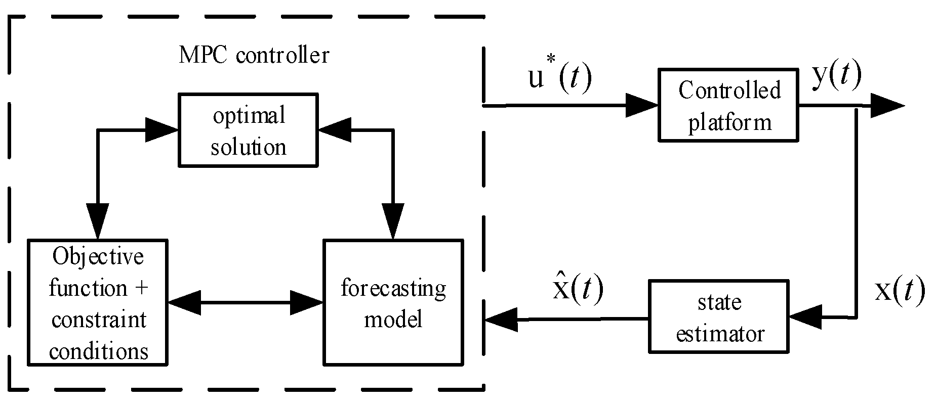
Figure 7 is the block diagram of model predictive control.
The MPC controller combines the prediction model, the objective function and the constraint conditions to obtain the optimal control sequence at the current time. It is input into the controlled platform, and the controlled platform is controlled according to the current control output , and then the current state observation value is input into the state estimator. The estimator estimates the state variables that cannot be observed by the sensor or the observation cost is high. The estimated state quantity is input into the MPC controller, and the optimization solution is carried out again to obtain the control sequence for a period of time in the future.
3.1. MPC Active Seat Suspension Control Principle
There are some uncertainties and constraints in the process of tractor driving and working, including the change of working state and the change of driving road environment. The model predictive control theory has strong adaptability to this uncertainty, and provides an effective control method for the tractor active seat suspension system. The characteristics of the system are that the tractor active seat suspension minimizes the seat acceleration and tire dynamic displacement within the range of the actuator active power and the allowable dynamic deflection of the seat suspension. The traditional control algorithm can not deal with the input, state and output constraints in the process, so that it can not achieve the optimal control effect. MPC can optimize the state information and constraints of each control cycle of the seat suspension system in the finite prediction domain, so that the controller can be optimized at each moment.
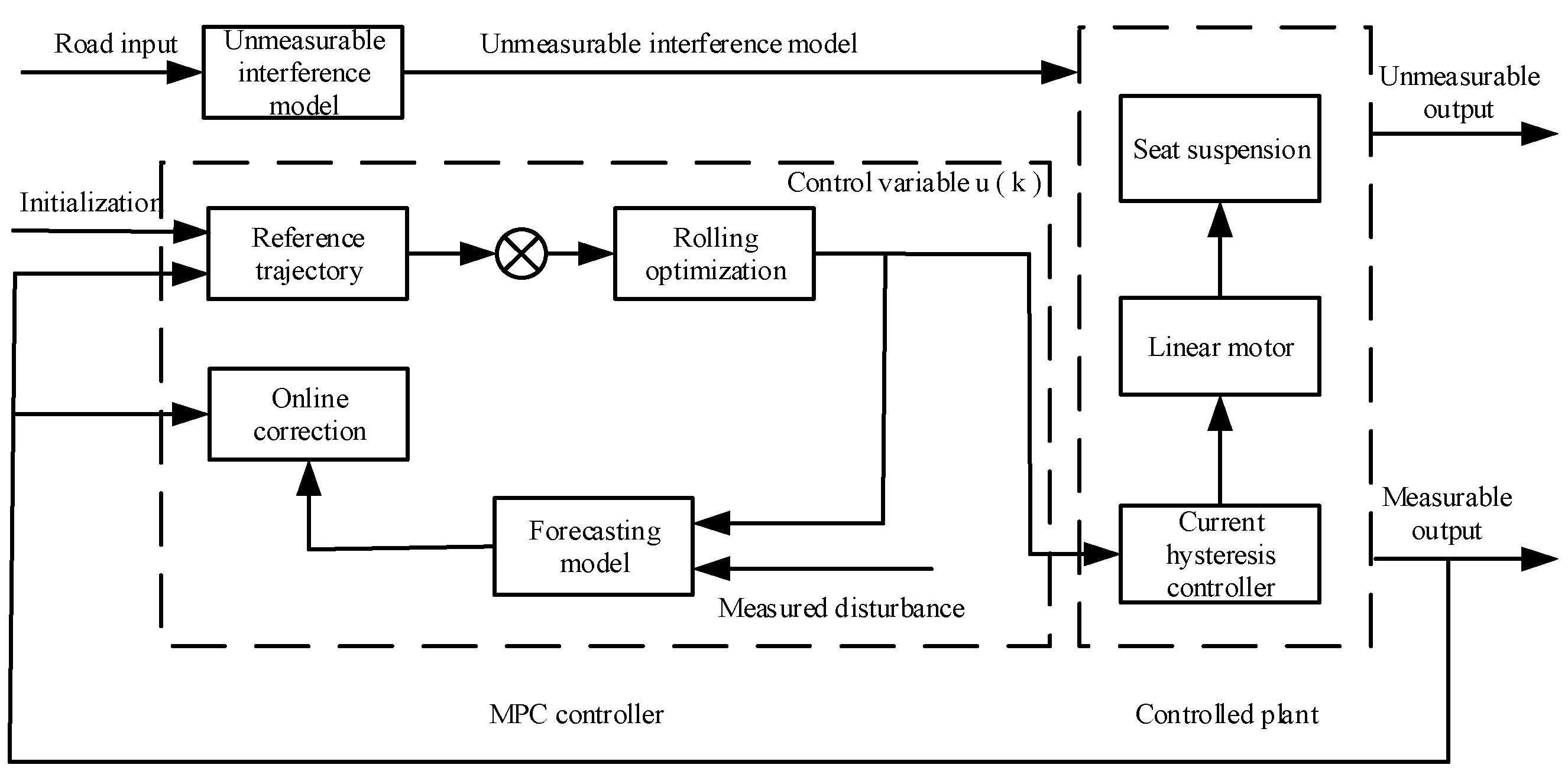
Tractor active seat model predictive control system structure is shown in
Figure 8.
3.2. Forecasting Model
Model predictive control solves the optimal problem in the discrete time domain by aiming at the state and constraint conditions of each control period, so that the controller remains optimal at each moment. Therefore, it is necessary to discretize the existing continuous-time state equation (14).
The discretized state equation can be expressed as:
Where:
is the sampling time,
is the coefficient matrix of discrete system under sampling period, is the discrete time of the system, is the integral time constant.
In MATLAB, the discrete model matrix
can be obtained by “c2d” function and setting a sampling time
.
3.3. Rolling Optimization
Model predictive control obtains the optimal control quantity by optimizing a performance evaluation index. Different from other traditional control algorithms, this optimization process is repeated online. The purpose of rolling optimization is to determine the control effect in the future by minimizing a certain performance index, namely seat suspension acceleration and tire dynamic displacement. The objective of the MPC controller is to find the optimal control rate, and to optimize the ride comfort and stability of the tractor under the constraint conditions. By solving the minimum value of the objective function, the control vector of the minimum value of the objective function at the current time is found, and the elements in are the active control force F. The purpose of optimization is to minimize the objective function, and the quadratic performance index is selected as the rolling optimization objective function:
Let be the weighted matrices of output variables and control variables, respectively. The optimization goal is mainly aimed at the dynamic performance of the system in the prediction time domain, and only the first item of the optimal control sequence is applied to the controlled process, that is, the control increment at time is , where the variable can be solved offline in advance. After the new measurement value is obtained at the next sampling time, the above optimization problem will be re-solved to obtain a new control sequence, so as to achieve rolling optimization.
In order to achieve optimal performance control under actual operating conditions, the constraints of the controller must be considered, so the control quantity and control increment must be constrained.
In the optimization design of the seat suspension, according to the characteristics of the active seat suspension controller, in addition to meeting the requirements of the objective function, certain constraints must be met to make the optimization results meet the design requirements. The rolling optimization constraints are:
According to the road surface and field working conditions of the tractor, the tractor is prevented from slipping on the muddy and loose soft soil road surface during operation. The static load of the tire is greater than the dynamic load of the tire to ensure that the tire and the ground always have good ground adhesion
The height of the road profile of the tractor driving on the D and E road surfaces is high, resulting in a larger amplitude and displacement of the seat suspension. The dynamic stroke of the seat suspension should be within the dynamic deflection range to avoid damage to the mechanical structure of the suspension . is the allowable dynamic deflection of the seat suspension.
The output of the controller control force is less than the maximum output force of the seat suspension controller to ensure that the controller is always in normal working condition.
3.4. Feedback Correction
In order to suppress the control deviation caused by model mismatch or environmental interference, that is, after the controlled object receives the control signal of the predictive controller at time
, the actual output
of the controlled system at time
is not equal to the model prediction output
,which constitutes a prediction error.
Therefore, at the new sampling time, the actual output of the object is first detected, and this real-time information is used to weight the model-based prediction, and then a new optimization is performed.
Where
is the system output predicted by the system at time
after error correction,
is the error correction vector,
.
The predicted initial value at the next moment is the corrected, and the predicted initial value at is used to predict the future moment .
The predicted initial value at the next moment can be obtained :
4. Active Control and Simulation Analysis of Active Seat Suspension
In order to verify the damping effect of the proposed model predictive controller on the active seat suspension of the tractor and consider the influence of the parameter change of the seat suspension system on the dynamics, this chapter selects three evaluation indexes of seat acceleration, seat suspension dynamic deflection and tire dynamic displacement to simulate the amplitude-frequency characteristics of the 3-degree o -freedom 1 4 vehicle active seat suspension model. The Matlab MPC toolbox is used to simulate the MPC active seat suspension. The generation and implementation of MPC in the system mainly includes three steps.
4.1. Define the System Model
The whole prediction process depends on the accuracy of the established model, so defining the system model-state space model is the key to MPC design. The establishment of the state space model According to the state space equation of the dynamic model of the tractor active seat suspension system determined in
Section 2.3, the established system model is imported into the MPC controller.
4.2. Define the Input and Output of MPC
According to the structure of the tractor seat suspension and the behavior and control characteristics of the system, the input and output of the active seat suspension model are accurately defined. In the tractor active seat suspension system, the active actuator output active power is required to act on the seat suspension to attenuate the vibration. Therefore, the actuator active power F is defined as the control variable (), that is, the input of the seat suspension system. Then the state variable of the system is selected as the measurable output () of the MPC controller. According to the actual situation, the constraints of MPC are defined by considering the system constraints. First of all, the dynamic stroke of the seat suspension should be within the dynamic deflection range to avoid damage to the mechanical structure of the suspension. Secondly, the output of the controller control force should be less than the maximum output force of the seat suspension controller to ensure that the controller is always in normal working condition. The input of MPC is defined as the main power F(N).The output of MPC is defined as human-seat acceleration ,(m / s2).The seat suspension stroke constraint is 0.08 m, the output active force range is , and the change rate range is .
4.3. Set MPC Controller Parameters
Define the input and output() of the MPC controller, and finally set the MPC controller parameters. The sampling time () is defined as 0.01 seconds, the predictive time domain () is 10, and the control time domain () is 2. The MPC controller parameters are defined and the controller is simulated in the MPC control box. According to the control characteristics of the seat suspension, the active seat suspension generates the active force through the active actuator, which can keep the seat upper plate stable under the perfect control and ideal state. That is to say, the MPC control behavior expects that the vibration acceleration of the upper surface of the seat in contact with the human body is 0 when the road vibration is input into the suspension system, so the state reference value is set to 0.
4.4. System Simulation Implementation and Application Result Analysis
After defining the system model, defining the input and output of MPC and setting the parameters of model predictive controller, according to the established mathematical model of active seat suspension and the designed MPC controller, the simulation model of the system is established and analyzed in MATLAB / Simulink. The classical PID control algorithm is easy to adjust and the control algorithm parameters are simple. It is widely used in seat suspension control applications. Therefore, the comparison algorithm in this paper selects PID control algorithm. The output results of passive seat suspension, PID control active seat suspension and model predictive control active seat suspension are placed in an oscilloscope to observe the performance of seat suspension under the control of each controller. The passive seat suspension has zero active power output. The Simulink simulation model diagram of the whole system of tractor seat suspension is built. The simulation parameters of tractor seat suspension are shown in
Table 1.
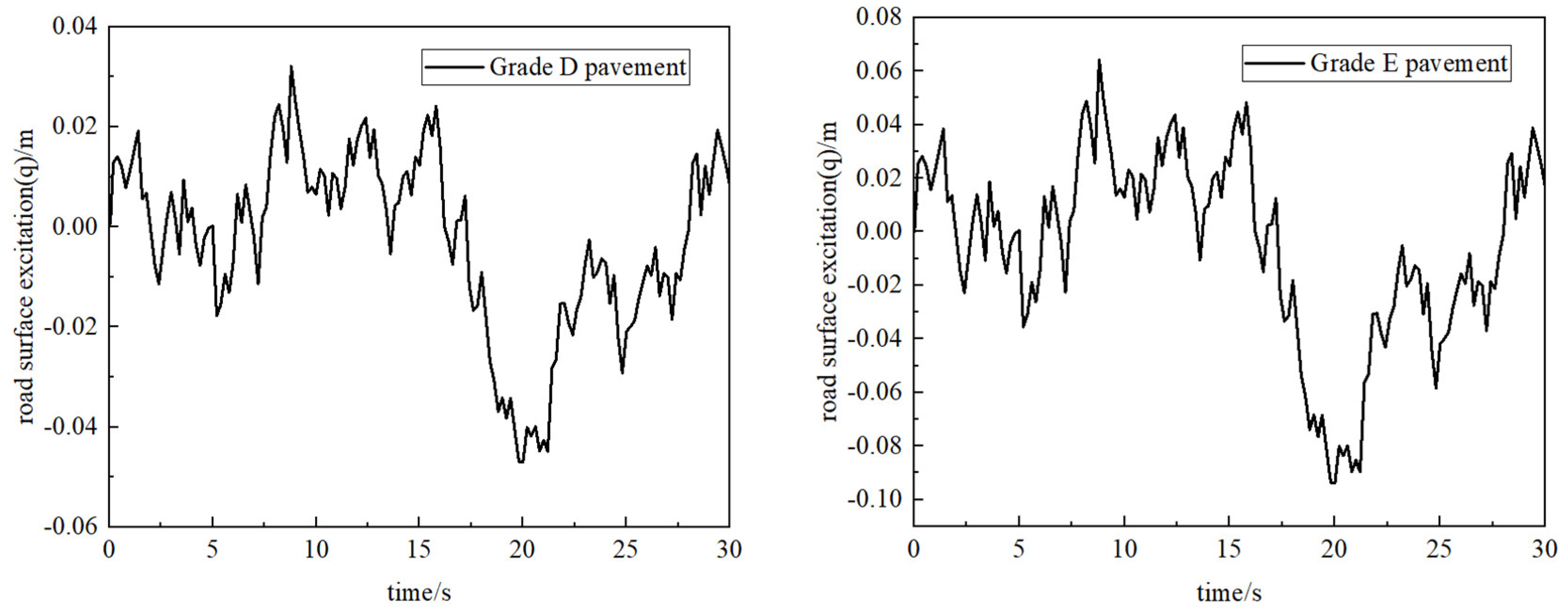
Combined with the characteristics of the road and working conditions of the tractor, the D and E random road input excitation models are first established as the vibration input of the whole seat suspension system. The vibration sources of tractor seat mainly include engine vibration and ground excitation input. Most of the periodic vibration and high frequency vibration caused by engine vibration have been isolated by the seat system, so this paper mainly studies the random vibration in the low frequency range caused by ground uneven excitation. According to the complex road conditions in the field when the tractor is driving and operating, this paper selects the D and E-level road excitation as the field rugged road surface. According to the 'vehicle vibration input-road surface flatness representation ', the following is the time domain expression of road roughness [18].
Where
is road displacement,
is the road roughness coefficient,
under D-class pavement and
under E-class pavement,
is the lower cut-off frequency
,
,
is Gaussian white noise with mean value of 0.
The time domain model of road roughness is built in the Matlab/Simulink environment. According to the actual driving conditions of the tractor (including the transfer and transportation of the tractor) and the road roughness of the field operation, the D-class road surface at the speed of 20km / h is selected to simulate the transfer and transportation of the tractor in the non-road field rugged road year, and the E-class road surface simulation tractor at the speed of 10km / h is selected to analyze the field operation and verify the model, as shown in
Figure 9. The sampling time is 0.005 s, and the simulation time is 30 s.
The practical application effect of tractor active seat suspension system based on model predictive control strategy is analyzed, and compared with traditional PID control and passive seat suspension system.
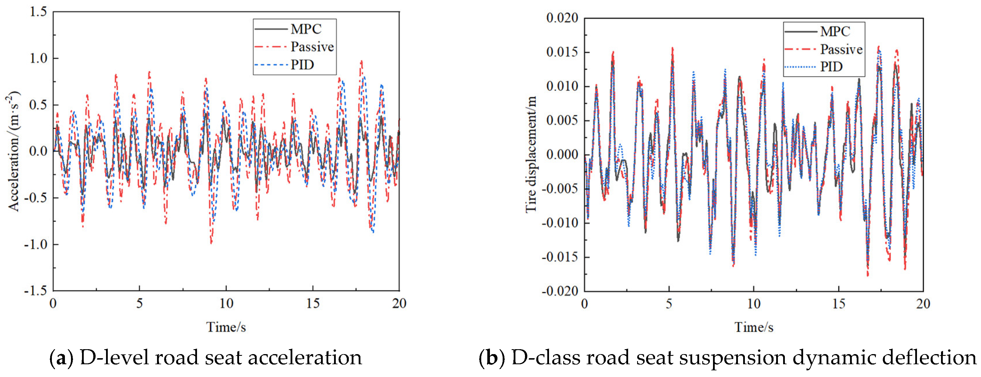
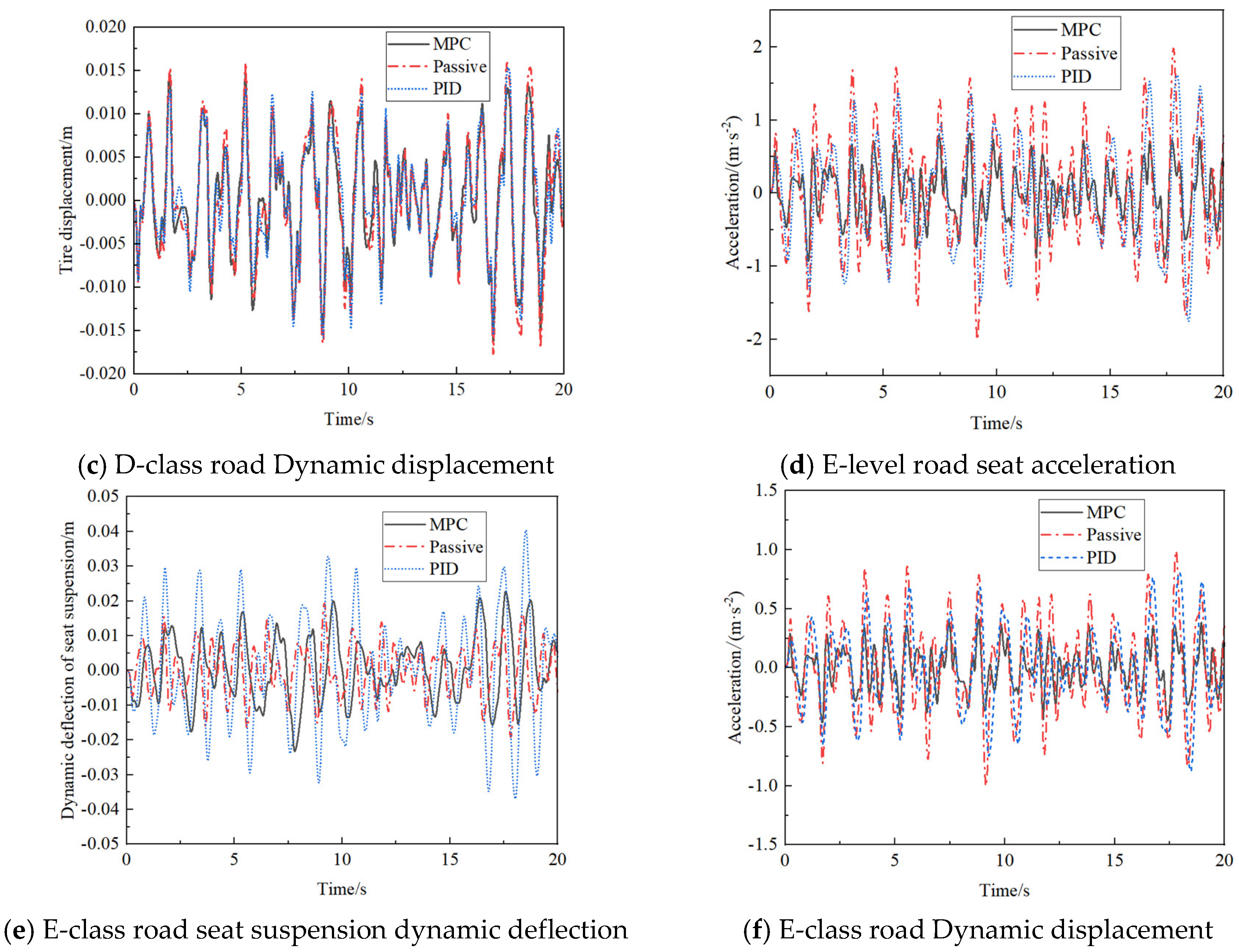
Figure 10 is the simulation results of human-seat acceleration, suspension dynamic deflection and tire dynamic load of seat suspension under different road excitation.
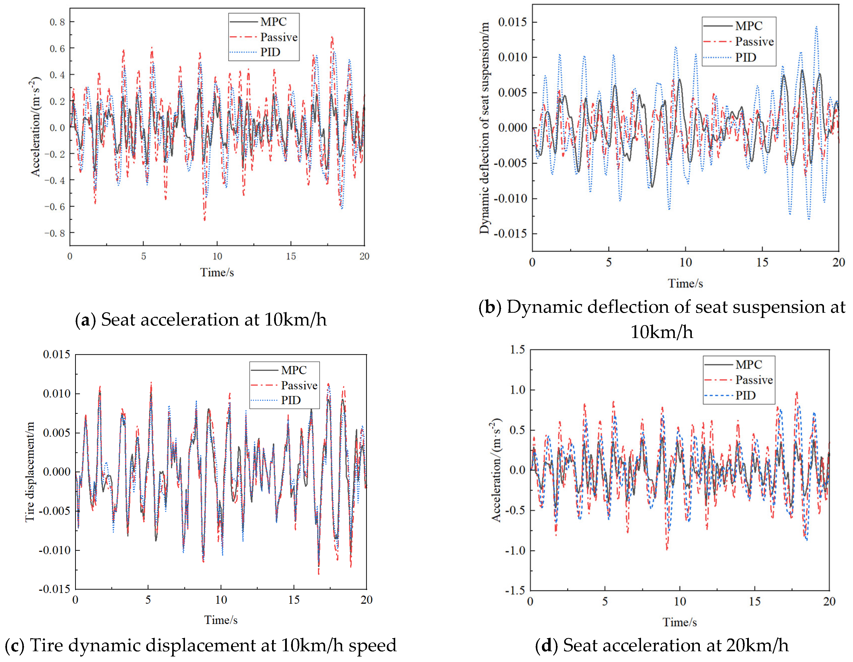
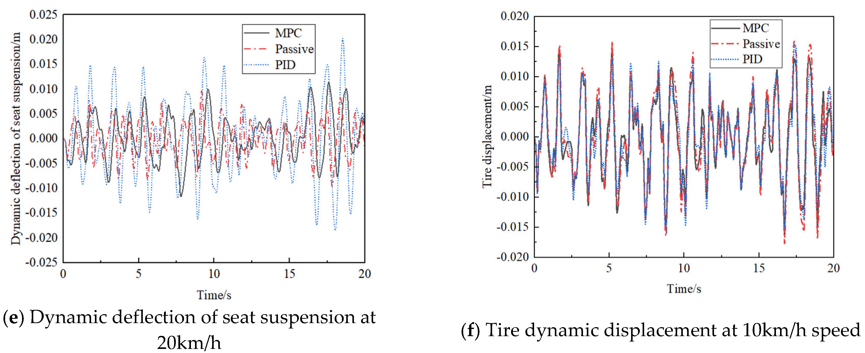
Figure 11 is the simulation results of human-seat acceleration, suspension dynamic deflection and tire dynamic load of seat suspension at different speeds.
It can be seen from
Figure 10 and
Figure 11 that under different driving speeds (10km/h and 20km/h) and different levels of road surface (D and E) excitation. In terms of human-seat vertical vibration acceleration, MPC active seat suspension system has the best effect, and has obvious advantages over passive seat suspension and PID seat suspension, PID control active seat suspension is the second, and passive seat suspension is the worst. For the dynamic deflection of the seat suspension, the passive seat suspension is the best, the MPC seat suspension is the second, and the PID seat suspension is the worst. This is due to the characteristics of the active seat suspension controller, in order to achieve the optimal goal, while reducing the performance of other targets. In order to achieve the optimal vibration reduction effect, the active seat suspension sacrifices the displacement of the seat suspension, resulting in an increase in dynamic deflection, but the dynamic deflection of the MPC and PID seat suspensions is still within the dynamic deflection limit. For the dynamic displacement of the tire, the dynamic displacement performance of the three seat suspensions is not much different. The MPC seat suspension has the best performance, followed by the PID seat suspension, and the passive seat is the worst. The root mean square values of acceleration, dynamic deflection and dynamic displacement of active seat suspension system based on model predictive control and PID, passive seat suspension seat system are shown in
Table 2.
Compared with the passive seat suspension, the mean square of seat vertical vibration acceleration of MPC active seat suspension is reduced by 52.5 %, and the root mean square of tire dynamic displacement is reduced by 64.3 %.Compared with the PID active seat suspension, the root mean square of the vertical acceleration of the seat center of mass is reduced by 45.5 %, and the root mean square of the tire dynamic displacement is reduced by 55.9 %.The MPC active seat suspension effectively reduces the human-seat vibration acceleration, improves the ride comfort of the tractor, reduces the dynamic displacement of the tire, improves the grip of the tractor tire under various complex road conditions and driving conditions, and improves the driving stability of the tractor.
In order to consider the dynamic response of the seat suspension to the change of load mass, the suspension performance under different load mass m
se is compared and analyzed. In the dynamic model of the tractor active seat suspension system established in
Section 2.3 of this paper, m
se is the combined mass of human and seat. Here, the dynamic response of MPC active seat suspension to load mass change is mainly considered.
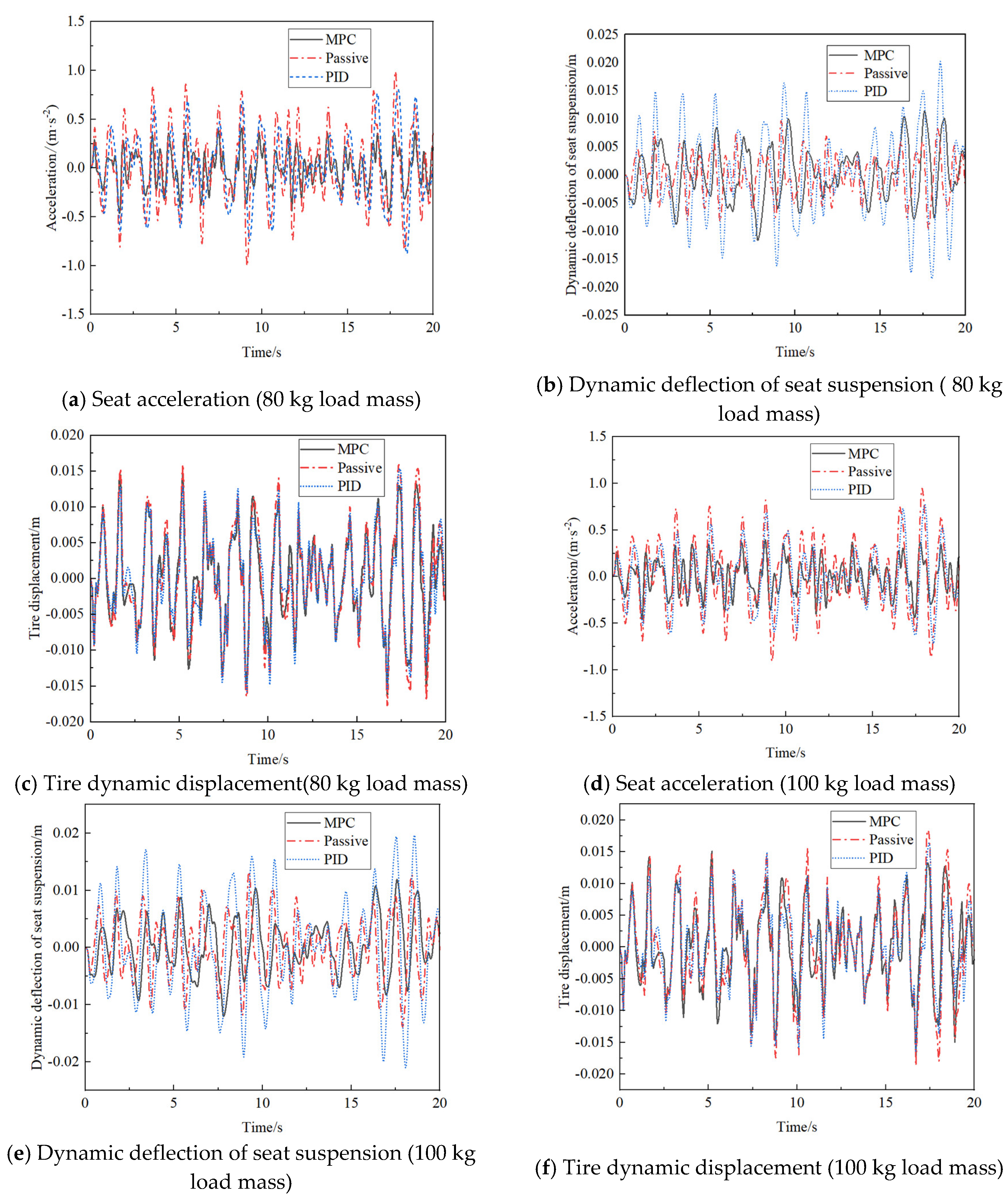
Figure 12 is the simulation results of human-seat acceleration, suspension dynamic deflection and tire dynamic load of seat suspension under different load masses. It can be seen from
Figure 12 that with the increase of load mass, the acceleration of passive and PID seat suspension, the dynamic deflection of seat suspension and the dynamic displacement of tire increase, that is, with the increase of load mass, the evaluation index of human comfort vibration decreases.
It can be seen from
Table 3 that when the load mass changes, the human-seat acceleration, seat suspension dynamic deflection and tire dynamic displacement of the MPC active seat suspension system do not change much. As the load mass increases, the seat vibration acceleration increases by 11.4 %, the seat suspension dynamic deflection decreases by 9.12 %, and the tire dynamic displacement decreases by 8.1 %. The MPC active seat suspension system has better vibration control characteristics than the passive system when the load mass increases, and has better robustness to load mass changes. MPC has dynamic characteristics, can solve problems such as sudden interference, and has good performance.
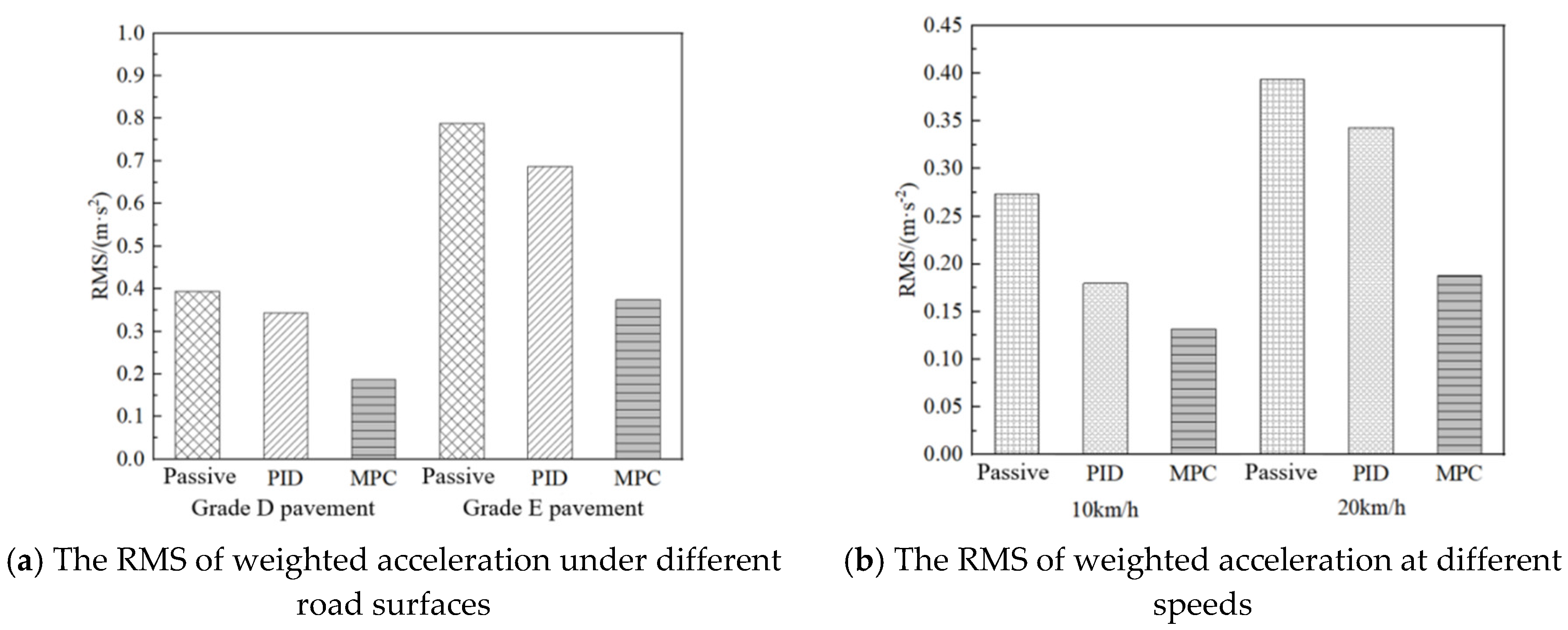
As the most important one of the three performance indexes of seat suspension, the vertical vibration acceleration of human-seat is analyzed and compared separately. The weighted vertical acceleration of MPC active seat suspension system and PID seat suspension system under different road types and different vehicle speeds is shown in
Figure 13. Considering the real road conditions of the tractor, as well as the speed of the working condition and the non working condition. Under different road level (D and E) excitations and different driving speeds (10km/h and 20km/h), with the increase of road level, that is, the larger the random road input amplitude and the larger the speed, the MPC active seat suspension can still reduce the vertical vibration acceleration amplitude of the seat by 52 %, which greatly improves the vibration reduction effect, thereby improving the ride comfort of the tractor driver.
5. Conclusions
Based on the 1/4 vehicle-seat suspension model, the active seat suspension model predictive controller is designed. The control results of the seat suspension are simulated and analyzed under different random road input types, vehicle speed and load quality test conditions. Comprehensively considering the three evaluation indexes of human-seat mass vibration acceleration, seat suspension dynamic deflection and tire dynamic displacement, the seat vibration acceleration is the most obvious improvement among the above three evaluation indexes. The seat acceleration can more accurately evaluate the human ride comfort and vehicle ride comfort, and significantly improve the tractor in the field operation with large road surface excitation and the influence of driver exposure to various complex and strong vibration on driver comfort.
The MPC active seat suspension controller designed in this paper, by setting the appropriate controller parameters and selecting the weight of input and output, the comprehensive performance of the vehicle seat MPC active suspension is obviously better than that of the PID control active suspension and passive suspension, and the comprehensive performance is the best in the three suspension control. The ride comfort of tractor is 52 % higher than that of passive seat suspension, and 45 % higher than that of traditional PID control seat suspension. Therefore, the designed tractor active seat suspension based on model predictive control has better vibration reduction characteristics and improves ride comfort. When the load mass changes, the root mean square value of the human-seat acceleration of the MPC active seat suspension changes by 11.4 %, the root mean square value of the seat suspension dynamic deflection changes by 9.12 %, and the root mean square value of the tire dynamic displacement changes by 8.19 %. The numerical variation range of these three evaluation indexes is about 10 %, which has good dynamic characteristics and can solve the problems of sudden interference. The results of this study can provide a theoretical basis for further research and future active seat suspension control work.
Funding
The National Key R&D Program of China (2022YFD2001203,2022YFD2001201B); Key agricultural core technology research project (NK202216010103); Open Project of State Key Laboratory of Tractor Power System (SKT2022001); 2022 Plan for Key Scientific Research Projects in Colleges and Universities of Henan Province (22B416001).
Institutional Review Board Statement
Exclude this statement.
Informed Consent Statement
Informed consent was obtained from all subjects involved in the study.
Data Availability Statement
No new data were created or analyzed in this study. Data sharing is not applicable to this article.
Conflicts of Interest
The authors declare no conflicts of interest.
References
- Yang, Y.; Cheng, S.K.; Qi, J.et al. Design and Experiment of Automatic Leveling System for Agricultural Machinery Seat Based on Ergonomics. Trans. Chin. Soc. Agric. Mach. 2022, 53, 434–444.
- Wang Q C, Huo Y H, Xu Z, et al. Effects of backrest and seat-pan inclination of tractor seat on biomechanical characteristics of lumbar, abdomen, leg and spine. Comput. Methods Biomech. Biomed. Eng. 2022, 26. [CrossRef]
- Chen M, Zhao Q H, Yang J Z, et al. Research on the vibration response of three-dimensional sitting human model considering seat design. J. Qingdao Univ. 2022, 37, 49–60.
- Gao R T, Wang Y, Yang Z, et al. Tractor Driving Seat Suspension System Research Status and Strategies in China: A Review. IFAC Pap. Online 2018, 51. [CrossRef]
- Aisyah Adam, Nawal A, Abdul jalil.Vertical Suspension Seat Transmissibility and SEAT Values for Seated Person Exposed to Whole-body Vibration in Agricultural Tractor Preliminary Study. Procedia Eng. 2017, 170. [CrossRef]
- Zhao, Q.; Zhang, N. Design of Canopy backstepping Controller for Vehicle Active Seat Suspension. Noise Vib. Control 2018, 38, 12–17.
- Wang X L, Huang J Y, Lv H F, et al. H∞ optimal control of vehicle semi-active seat suspension system based on sliding mode observer. Vib. Shock 2022, 41, 246–251.
- Sha S J, Wang Z G, Du H P. Research on the performance of semi-active seat suspension system of vehicle using magnetorheological damper. Mech. Des. Manuf. 2021, 370, 48–53. [CrossRef]
- Ma Shuo, Jiang H, Guo X L, et al. Research on active seat suspension system based on low-pass filter PID control. J. Liaocheng Univ. 2023, 35, 1–7.
- Luan G G, Liu P F, Ning D H,et al. Semi-Active Vibration Control of Seat Suspension Equipped with a Variable Equivalent Inertance-Variable Damping Device. Machines 2023, 11. [CrossRef]
- Munyaneza Olivier, Sohn Jung Woo. Modeling and control of hybrid MR seat damper and whole body vibration evaluation for bus drivers. J. Low Freq. Noise Vib. Act. Control. 2022, 41. [CrossRef]
- Phu Do Xuan, Mien Van, Choi SeungBok. A New Switching Adaptive Fuzzy Controller with an Application to Vibration Control of a Vehicle Seat Suspension Subjected to Disturbances. Appl. Sci. 2021, 11. [CrossRef]
- Jay, H. Lee. Model predictive control: Review of the three decades of development. Int. J. Control. Autom. Syst. 2011, 9. [CrossRef]
- JNarayan, S.A. Gorji, M.M. Ektesabi. Power reduction for an active suspension system in a quarter car model using MPC. In Proceedings of the 2020 IEEE International Conference on Energy Internet (ICEI), 2020; pp. 140–146.
- Huang, K.; Yu, F.; Zhang, Y.C. Design of Model Predictive Controller for Electromagnetic Active Suspension. J. Shanghai Jiaotong Univ. 2010, 44, 1619–1624.
- Zhao, Q.; Yin, J.X. Predictive Control of Vehicle Electro-hydraulic Active Suspension. J. Wuhan Univ. Technol. 2014, 38, 979–983.
- Yu F. Vehicle Dynamics and Control; People's Communications Press: Beijing, China, 2003; pp. 23–24..
- Ning D H, Jia Z J, Dong M M, et al. Research Progress of Vehicle Seat Suspension Damping System. J. China Jiliang Univ. 2018, 29, 113–120.
- Mohammed Al-Ashmori,Xu Wang. A Systematic Literature Review of Various Control Techniques for Active Seat Suspension Systems. Appl. Sci. 2020, 10. [CrossRef]
- Yu Y W, Zhao L L, Zhou C C, et al. Design and Analysis of Vehicle Seat Suboptimal Control Active Suspension. J. Beijing Univ. Posts Telecommun. 2021, 44, 87–93.
- Du H P,Li W H,Zhang N.Integrated seat and suspension control for a quarter car with driver model. IEEE Trans. Veh. Technol. 2012, 61. [CrossRef]
- Kuznetsov A,Mammadov M,Sultan I,et al. Optimization of a quarter-car suspension model coupled with the driver biomechanical effects. J. Sound Vib. 2011, 330, 2937–2946. [CrossRef]
- Wang R C, Xie J, Ye Q, et al. Modeling and Experimental Study of Linear Motor Active Suspension. Automot. Eng. 2016, 38, 495–449. [CrossRef]
- Gong, J.W. Model Predictive Control of Driverless Vehicle; Beijing Institute of Technology Press: Beijing, China, 2020; pp. 57–60.
- Durmaz, B.E.; Kaçmaz, B.; mutlu, I. Implementation and comparison of LQR-MPC on active suspension system. In Proceedings of the International Conference on Electrical and Electronics Engineering, ELECO, 2017; pp. 828–835.
- I Maciejewski; S Glowinski,T. Krzyzynski. Active control of a seat suspension with the system adaptation to varying load mass. Mechatronics 2014, 24. [CrossRef]
- Papadimitrakis Myron,Alexandridis Alex. Active vehicle suspension control using road preview model predictive control and radial basis function networks. Appl. Soft Comput. 2022, 120. [CrossRef]
|
Disclaimer/Publisher’s Note: The statements, opinions and data contained in all publications are solely those of the individual author(s) and contributor(s) and not of MDPI and/or the editor(s). MDPI and/or the editor(s) disclaim responsibility for any injury to people or property resulting from any ideas, methods, instructions or products referred to in the content. |
© 2023 by the authors. Licensee MDPI, Basel, Switzerland. This article is an open access article distributed under the terms and conditions of the Creative Commons Attribution (CC BY) license (http://creativecommons.org/licenses/by/4.0/).
