ACM Reference Format:
Rajesh Kumar Datta. 2018.
CVM: Crossbar-based circuit Verification through Modeling. In
Proceedings of ACM Conference (Conference’17). ACM, New York, NY, USA, 3 pages.
https://doi.org/XXXXXXX.XXXXXXX
Permission to make digital or hard copies of all or part of this work for personal or classroom use is granted without fee provided that copies are not made or distributed for profit or commercial advantage and that copies bear this notice and the full citation on the first page. Copyrights for components of this work owned by others than ACM must be honored. Abstracting with credit is permitted. To copy otherwise, or republish, to post on servers or to redistribute to lists, requires prior specific permission and/or a fee. Request permissions from permissions@acm.org.
Conference’17, July 2017, Washington, DC, USA
© 2018 Association for Computing Machinery. ACM ISBN 978-1-4503-XXXX-X/18/06… $15.00
1. Introduction
Crossbar-based circuits are a promising substitute for traditional CMOS-based circuits as the latter approach has limitations in further miniaturization. In [
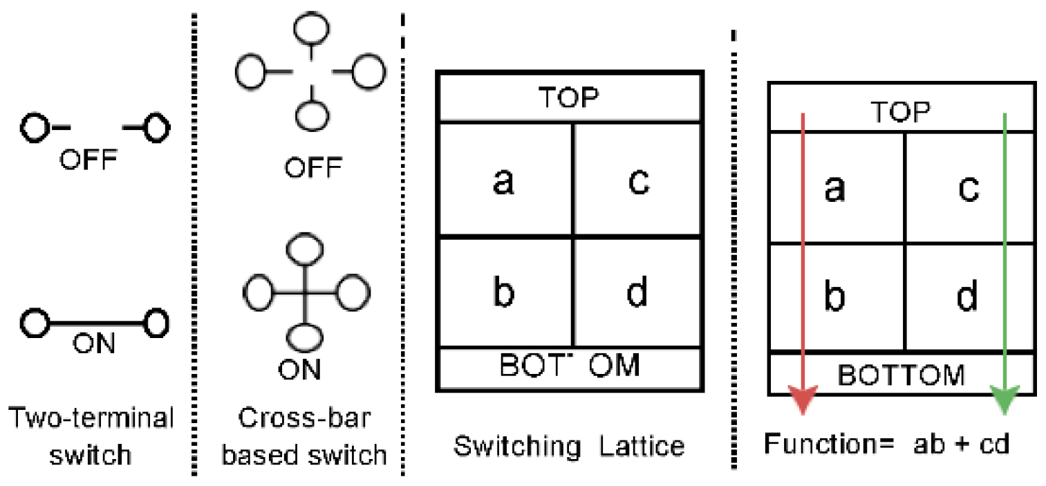
3] the concept of four terminal or crossbarbased implementation of boolean function was proposed. These switches offer a more efficient implementation of Boolean functions with fewer switches compared to traditional CMOS switches. Twoterminal switches are controlled by Boolean literals, with a value of ‘1’ turning the switch ON and ‘0’ turning it OFF. In contrast, Cross-terminal switches are arranged in a rectangular lattice and can be mutually ON or OFF. These switches can also be controlled by Boolean literals and offer more connection flexibility. Technology development and circuit modeling of these structures were discussed in [8]. Different methods have [2,7] shown the implementation of the Boolean function with cross-bar-based switching lattices. The idea of using two-dimensional arrays of rectangular switches is not new [1]. In recent years, the four-terminal switch model has gained renewed attention due to advances in technology [4,5]. Boolean functions can be implemented using crossbar-type switches [6,9].
Figure 1 and
Figure 3 summarize the basic concept. In this work, we have presented the idea and implementation of CVM, which can be used to verify the accuracy of crossbar-based implementations of any given function. This is accomplished by modeling the characteristics of the lattice and comparing the output with the expected result.
2. Modeling of Lattice Network
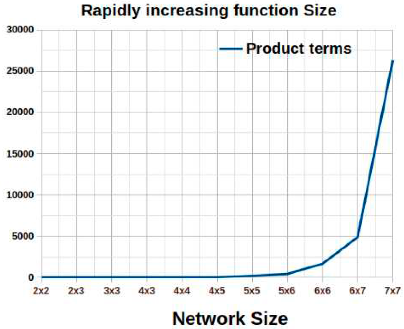
Given a lattice network, the position of the Boolean literals can be identified. However, as the size of the network increases, it becomes more difficult to verify the function implemented by the network due to the rapid increase in the number of product terms.
Figure 2 presents the rapid increase of function size in the lattice network. To simplify the process of verifying the Boolean function implemented by a given lattice network, we can create a
model of the network and find the SOPs implemented by it. This can make the verification process easier. Next, we will discuss the modeling technique of any lattice implementation.
Formation of a Lattice If we take a 3x3 lattice network (
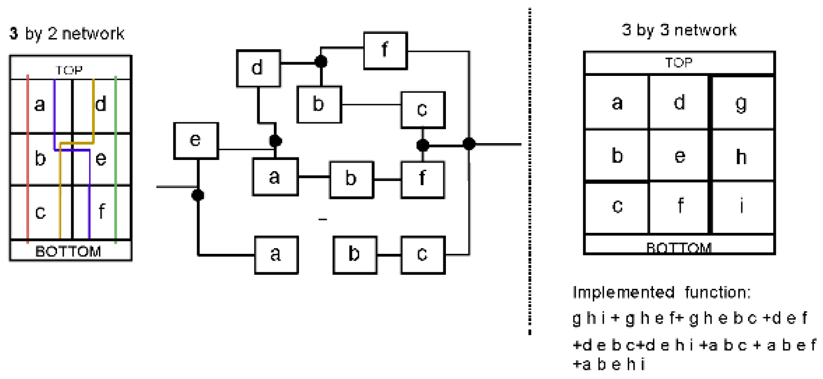
Figure 3 right side), it contains 9 four-terminal switches, with the top and bottom parts referred to as ‘TOP’ and ‘BOTTOM’. Every path connecting the TOP to the BOTTOM is a Product term of the imple- mented Boolean function. The lattice network can be represented as a graph and DFS algorithm is used to find the paths.
Path formation To generate paths in a 3 by 3 lattice, we begin by checking the adjacent nodes (or ‘children’) of the source four- terminal switch. Each four-terminal switch can be connected to a maximum of four other switches, so each switch can have up to four children. In the 3 by 3 lattice shown in
Figure 3, the source node has three children: ‘a’, ‘d’, and ‘g’. We then choose one of these children, such as ‘a’, and check its children. ‘a’ has one child, ‘b’, which has two children: ‘e’ and ‘c’. If we choose ‘c’, the path reaches the bottom of the lattice and the product term becomes ‘a b c’. If we choose ‘e’ instead, it has two children: ‘h’ and ‘f’. If we choose ‘f’, the path reaches the bottom and the product term becomes ‘a b e f’. This process is repeated recursively until all nodes and their children have been examined. Nodes that have already been marked as used in a previous path are not checked again.
Figure 3.
(Left side) The implementation of the function X = abc+ abef+ debc+ def can be performed using either crossbarbased or two-terminal-based circuits. The crossbar-based implementation requires 6 switches, while the two-terminalbased implementation requires 11 switches. Lines from Top to Bottom shows the path which implements product terms of the function. In larger functions, the size of the network can be significantly reduced by using crossbar-based circuits. (Right side) A 3 by-3 switching lattice is also shown in the figure.
Valid path selection To determine if a generated path is a su- perset of another path, we have two options: we can either generate all the paths first and then check for supersets, or we can check the path as it is being generated. The latter option is faster, especially for large functions with many paths. When adding a new node to the path, we can check if it is a child of any previous node in the path, except for the one that brought us to the new node. This avoids the need to generate all the paths and then remove the supersets.
Repetition of literals To generate all possible paths in a lattice structure with repeated literals, we can initially treat all literals as distinct, and then replace the basic literals with the original, repeated literals. However, this may result in superset paths that need to be removed to obtain the final set of paths.
3. Implementation of CVM
To model a four-terminal lattice or cross-bar structure, all relevant features must be considered mentioned in the previous section. Once the model is designed, the implemented boolean function can be obtained and compared to the intended target function to ensure an accurate representation of the lattice structure’s behavior. We implemented and developed the verification tool CVM with the ‘C’ language. The input of the tool is the lattice structure. We will release the preliminary version of the code for this paper. A
demo of the tool is uploaded here as an anonymous user with some sample examples [?]. The user will give the input of the literals in the order of the structure. For example, in
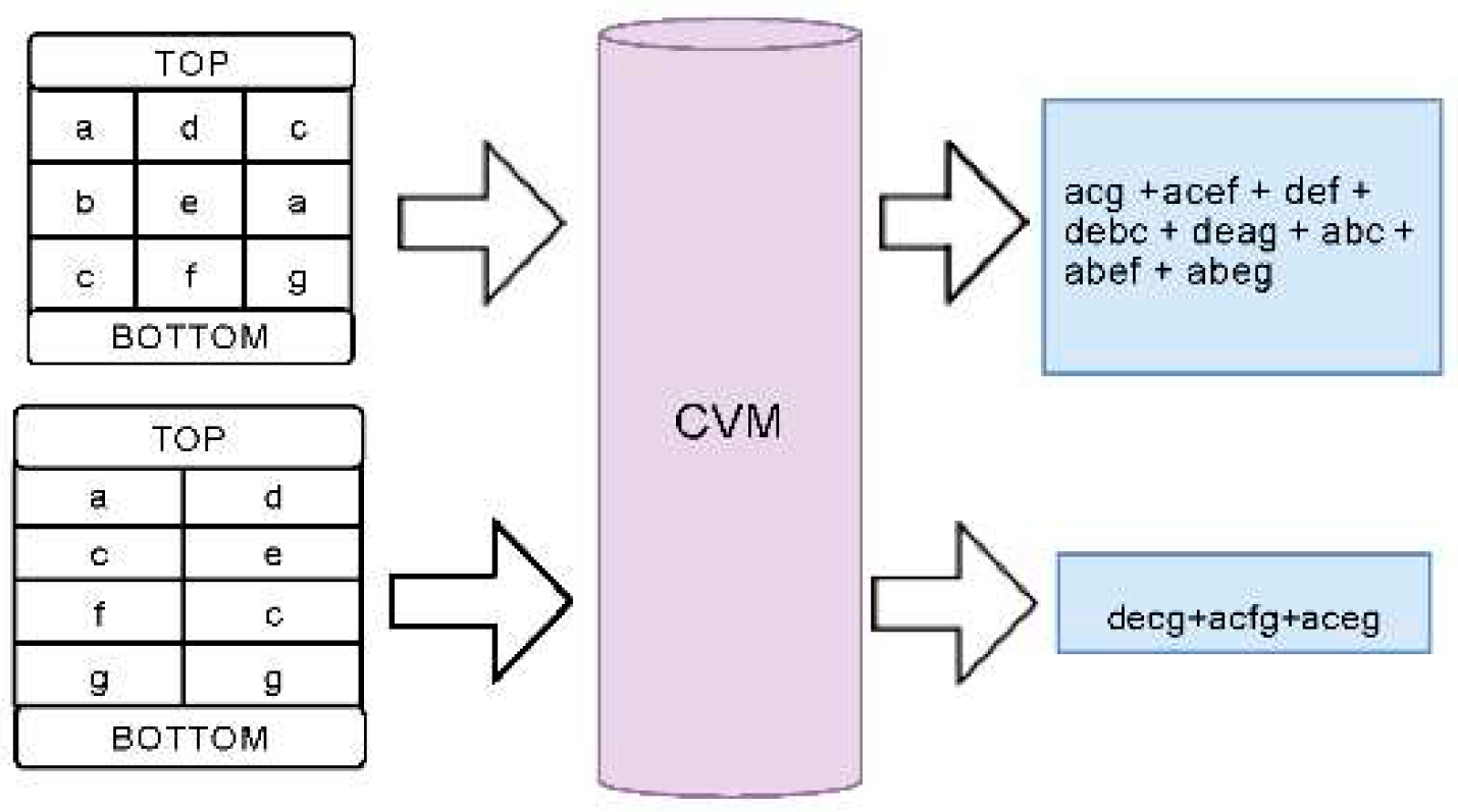
Figure 3 a 3x2 lattice has been shown. For the input of the tool, we can assume the literals as 1,2,3..6 for the literals a,b,c...f. At the output, the tool will provide the function’s product terms. If there is no repetition in the literals the lattice will generate the maximum number of product terms possible by the lattice. If there is a repetition of the literals there will be some invalid paths and CVM will discard those at the output. In
Figure 4 two sample lattice and their output has been shown which has been generated from CVM.
As we get the product terms of the lattice structure from CVM, we can verify if the lattice implements our required function or not. As in the bigger lattices, the number of product terms will be really high, CVM can help to understand if the implementation is correct or not.
4. Conclusions
In this work, we presented CVM for verifying any switching lattice network by modeling it. We have implemented the tool and verified the modeling methodologies with different lattice structures.
References
- Akers, S.B. A rectangular logic array. In 12th Annual Symposium on Switching and Automata Theory (swat 1971); IEEE: Piscataway, NJ, USA, 1971; pp. 79–90. [Google Scholar]
- Aksoy, L.; Altun, M. Novel Methods for Efficient Realization of Logic Functions Using Switching Lattices. IEEE Trans. Comput. 2020, 69, 427–440. [Google Scholar] [CrossRef]
- Altun, M.; Riedel, M.D. Logic synthesis for switching lattices. IEEE Trans. Comput. 2012, 61, 1588–1600. [Google Scholar] [CrossRef]
- Chrzanowska-Jeske, M.; Mishchenko, A. Synthesis for reg- ularity using decision diagrams [logic IC synthesis and layout]. In 2005 IEEE International Symposium on Circuits and Systems; IEEE: Piscataway, NJ, USA, 2005; pp. 4721–4724. [Google Scholar]
- Chrzanowska-Jeske, M.; Xu, Y.; Perkowski, M. Logic synthesis for a regular layout. VLSI Des. 1999, 10, 35–55. [Google Scholar] [CrossRef]
- Eshaghian-Wilner, M.M.; Flood, A.H.; Khitun, A.; Stoddart, J.F.; Wang, K. Molecular and nanoscale computing and technology. In Handbook of nature-inspired and innovative computing; Springer: Berlin/Heidelberg, Germany, 2006; pp. 477–509. [Google Scholar]
- Morgül, M.C.; Altun, M. Optimal and heuristic algorithms to synthesize lattices of four-terminal switches. Integration 2019, 64, 60–70. [Google Scholar] [CrossRef]
- Safaltin, S.; Gencer, O.; Morgul, M.C.; Aksoy, L.; Gur- men, S.; Moritz, C.A.; Altun, M. Realization of four-terminal switching lattices: Technology development and circuit modeling. In 2019 Design, Automation & Test in Europe Conference & Exhibition (DATE); IEEE: Piscataway, NJ, USA, 2019; pp. 504–509. [Google Scholar]
- Ziegler, M.M.; Stan, M.R. CMOS/nano co-design for crossbar- based molecular electronic systems. IEEE Trans. Nanotechnol. 2003, 2, 217–230. [Google Scholar] [CrossRef]
|
Disclaimer/Publisher’s Note: The statements, opinions and data contained in all publications are solely those of the individual author(s) and contributor(s) and not of MDPI and/or the editor(s). MDPI and/or the editor(s) disclaim responsibility for any injury to people or property resulting from any ideas, methods, instructions or products referred to in the content. |
© 2023 by the authors. Licensee MDPI, Basel, Switzerland. This article is an open access article distributed under the terms and conditions of the Creative Commons Attribution (CC BY) license (http://creativecommons.org/licenses/by/4.0/).


