1. Introduction
Hydrodynamic journal bearings are used in many high-speed rotating machineries. Among them, tilting pad journal bearings (TPJBs) offer more stability to the system [
1]. Hydrodynamic bearings are prone to rub-impact between the journal and the bearing due to their high-speed operation and low clearance between the journal and the bearing. Journal bearings are also exposed to experiencing wear due to insufficient oil film to separate the journal and the loaded part of the bearing in Run-up/shot-down phases. Therefore, rub-impact mainly occurs between the journal and loaded pads of TPJBs which can lead to material removal from the inner side of the bearing surface. Therefore, wear-induced geometrical imperfections are formed on the inner side of the loaded pads [
2]. As pad pivots tolerate weight of the rotor, the wear-induced geometrical imperfections of the pad are mostly created in front of loaded pad pivots. It is worth mentioning that for the load between pads (LBP) configuration of the TPJBs, the geometrical imperfection patterns are not equivalent in both loaded pads, since the loaded pad nearer to the journal suffers from more severe wear. These minor geometrical imperfections can negatively affect the TPJB dynamic behavior and change the dynamic behavior of the system at some speeds. For example, they can increase the vibration amplitude of the rotor, resulting in more severe wear and system failure [
3]. Therefore, early detection of journal-bearing contact and subsequent wear-induced bearing geometrical imperfections is crucial in preventing severe failure.
Mathematical simulations and experimental tests have been widely employed in previous studies for the description of the rotor-TPJB behavior. Dimond et al. [
4] reviewed the TPJB theory and showed the action of oil film-induced nonlinear forces on the system. The nonlinear behavior of TPJBs has been investigated by several researchers. Cloud et al. [
5] presented a five-pad TPJB model and analyzed the effects of two different pad clearances on the system stability by numerical simulation and experimental tests. They also showed that numerical simulations over-predict the stability thresholds compared to the experimental results. The rotor simulations are, however, verified experimentally by free-free modal tests, a better simulation is needed for fluid film bearing to obtain more accurate results. A nonlinear model of flexible rotor-TPJB was presented by Cao et al. [
6]. They analyzed the system behavior at equilibrium and numerically obtained the nonlinear dynamic response of the system for a flexible rotor-TPJB model. They did not, however, considered the effect of the temperature-induced oil film viscosity variations on the system equilibrium and dynamic response. The influence of the TPJB cross-coupling stiffness on the system dynamic behavior was analyzed by Synnegard et al. [
7]. They explored the effect of considering the TPJB cross-coupling stiffness in the simulation by numerical calculations and verified the results with the experimental bearing displacement values.
Nonlinear forces induced by oil film can lead to chaotic motion and instability in TPJBs. Kim and Palazzolo [
8] analyzed the bifurcation diagrams and stability of a five-pad TPJB. They also assessed the effects of oil film nonlinear forces on the quasi-periodic and chaotic motion of the system for a rigid rotor TPJB. The effects of pad preload on dynamic coefficients of the TPJBs were investigated by Dixit and Gupta [
9]. They studied the effects of different pad preloads on the system dynamic coefficients and fluid film pressure distribution, but the fluid film temperature changes due to the pad clearance variation were not addressed. Dang et al. [
10] presented an experimental procedure for pivot stiffness calculation and showed that pivot stiffness causes a reduction in TPJB dynamic coefficients. Hagemann et al. explored the transition between fully lubricated condition to partially lubricated condition in TPJBs [
11]. They showed that this transition occurs in certain spaces during run-up and shot-down phases, but they did not consider the effect of contact between journal and bearing in these phases. Bizarre et al. [
12] used the finite volume method for thermo-hydrodynamic simulation of a TPJB model. They studied the effects of oil film thickness on temperature and obtained its effects on the temperature distribution of the pads and the eccentricity of the journal. They also verified the simulations with experiments, but the dynamic behavior of TPJBs was not studied. Soltani and Naderan [
13] compared an isothermal 3D model of a TPJB with conventional 2D model and concluded that the results of 3D and 2D models are almost matched for heavier rotor with higher eccentricities. At lower eccentricities, more significant difference can be detected between the 3D and 2D models of the oil film. Therefore, the 2D model of the oil film could well identify the TPJB behavior for heavy rotors at higher shaft eccentricities. This paper failed to analyze the effect of temperature on the oil film behavior. Wanger and Allaire examined the effect of the pad pivot flexibility on the system frequency response in combination with the oil film effect [
14]. Furthermore, Jin et al. [
15] investigated the pivot stiffness effect on the vibration amplitude of TPJBs and showed that pivot stiffness leads to reduce the resonance and working amplitude of the system. Finally, Shin et al. [
16] published a review paper on thermal modeling methods for journal-bearing systems. They did not mention any previous works which simulated the effect of temperature-induced variations of the oil film viscosity on the dynamic behavior of a rotor-worn TPJB.
The nonlinear behavior of hydrodynamic bearings due to oil film forces can be affected by geometrical imperfections in journal and bearing. Bearing geometrical imperfections are created as a result of manufacturing errors and wear during the service time of the system. Wear can increase the loaded pads clearance and preload, therefore, changing the system behavior. Dufrane et al. [
17] measured wear depth on a worn plain bearing and suggested a mathematical relation to modify the oil film thickness formula in the worn area of the bearing. Gertzos et al. [
18] presented a computational model to simulate wear in a hydrodynamic plain bearings. They analyzed the eccentricity ratio changes, friction coefficient, attitude angle, and side oil flow versus the wear depth. Furthermore, The effects of wear was explored on the dynamic response of rotor-bearing system by Chasalevris et al. [
19]. According to their study, wear in the bearing is the source of additional harmonics in the frequency response of the system. They used continuous wavelet transform for wear detection in a plain bearing. Machado and Cavalca [
20] investigated the effects of hydrodynamic plain bearing wear on oil film pressure distribution, dynamic coefficients, and vibration amplitude. They reported an increase in journal-worn bearing vibration amplitude due to the bearing wear. Alves et al. [
21,
22] developed a model to describe wear in journal-hydrodynamic bearings. They used temperature and the system vibration spectral analysis to determine the severity of wear in plain bearings and concluded that wear increments the system anisotropy. Furthermore, they showed that wear-induced system anisotropy is more detectable in lower speeds as the rotor has higher eccentricity and rotates near the bearing.
The solid-to-solid contact between journal and the bearings is one of the main sources of hydrodynamic bearings wear and the bearing geometric imperfections induced by wear. Journal-bearing contact may occur due to several reasons such as slow operating speed or high mass unbalance of the rotor. Inclusion of the journal-bearing contact effect on the dynamic behavior of the system can lead to a more accurate simulation of the dynamic motion of the system which can be utilized for system fault diagnosis. The effects of the oil film in the contact region should be considered for precise simulation of the journal-bearing contact. To this end, a mixed elastohydrodynamic model can be implemented by assuming that surfaces are nominally smooth with a specified roughness. The solid-to-solid contact force is created due to contact between the asperity summits. In journal-bearing contact region, the oil film flows between the journal and the bearing surface asperities. This lubrication regime is called mixed-lubrication which was used by Kazama and Naritia [
23] to assess the effects of the wear-induced bearing geometrical imperfections on the solid-to-solid contact between a journal and a hydrodynamic plain bearing. They also obtained the oil film pressure distribution and the extent of the effect of bearing wear on a journal-worn bearing behavior at its equilibrium state. They, however, did not address the effect of bearing geometrical imperfections and journal-bearing contact on the dynamic behavior of the system. Varney and Green [
24] applied the mixed-lubrication theory to simulate the dynamic behavior of a rotor-circular stator experiencing rotor-stator rub-impact. They assumed the rotor and stator surfaces are rough and used asperity contact forces to simulate the rotor-stator contact. Xiang et al. [
25] simulated the interaction between wear and fluid-solid-thermal coupling in a sleeve lubricated bearing. They investigated the effect of the surface roughness to calculate solid-to-solid contact force in addition to examining the nonlinear behavior of a water lubricated bearing using a mixed-thermoelastohydrodynmaic lubrication model for the lubricant film [
26], They only studied the plain bearings and did not address the TPJBs behavior. Guo et al. [
27] implemented the mixed lubrication theory to simulate a misaligned rotor- bearing system that experiences a journal-bearing contact. They also considered the oil film temperature effect on the lubricant viscosity and pressure distribution and verified the results experimentally. They, however, did not investigate the journal-bearing dynamic motion in mixed lubrication regime.
In addition to the journal-bearing solid-to-solid contact and wear which lead to bearing geometrical imperfections, manufacturing errors is another source of journal-bearing geometrical imperfections. Dang et al. [
28] simulated the effect of TPJB geometric imperfections due to manufacturing errors. They investigated the effects of pad radius variations on a TPJB equilibrium position and the lubricant pressure distribution while neglecting the effect of TPJB geometric imperfections on the dynamic motion of the system. Lee et al. [
2] explored the effects of the use of worn pads on a TPJB equilibrium position. As wear mostly occurs at low speeds due to the lack of adequate oil film to separate the journal and the bearing, they created an artificial geometrical imperfection on the loaded pads and analyzed the effects of geometrical imperfections on the temperature distribution of the worn pads. They also found the journal equilibrium position both numerically and experimentally. They reported an increase and a decline in the temperature of the loaded pads and upper pads, respectively. Zhang et al. [
29] experimentally investigated the effects of wear in pads and the journal geometrical imperfections on the behavior of TPJBs. They observed that bearing geometrical imperfections change the system vibration level at some speeds but they did not study the dynamic behavior of the system in frequency domain. Silva and Nicoletti [
30] studied the effects of uncertainty due to assembly error in pad clearances on the system dynamic coefficients. They showed that bearing asymmetry can cause an increase or decrease in TPJB dynamic coefficients. Furthermore, Lou et al. [
31] showed that small uncertainties in pivot position and pad angular extension do not have a significant effect on static characteristic of TPJB; whereas uncertainties in shaft radius, pad inner radius, and pivot radius in a specified preload could have a considerable influence on TPJB static characteristic. They did not study effect of TPJB geometric uncertainties on the dynamic characteristic of the system.
Wear in TPJBs can change the dynamic motion of the system therefore, monitoring the vibration component variations can be used as a tool to detect wear in journal-bearings at its early stages. Ranjan et al. [
32] employed wear debris, vibration, and temperature analysis to experimentally study the wear and journal-bearing rub-impact in a water lubricated TPJB. They mentioned a considerable increase in the amplitudes of 5X and 10X frequency component in the system vibration signals due to wear and metal-metal contact between the journal and the bearing. Zhou et al. [
33] also showed that a water lubricated TPJB which operates in mixed lubrication regime, experiences lower contact load in heavy load conditions in comparison with conventional water lubricated bearings. Dixit and Gupta [
34] used the short bearing assumption to evaluate the effects of the TPJB geometrical parameters on the oil film dynamic coefficients. They showed that an increase in bearing clearance changes the oil film stiffness but did not consider the effect of possible contact between journal and bearing which may occur as a result of variations in the bearing stiffness. The effects of geometrical imperfections of the TPJB bearing on the dynamic behavior of the system was studied before [
35], while neglecting the effect of the oil film temperature variations due to the bearing geometrical imperfections on the system dynamic coefficients and the effect of bearing wear on the rotor-bearing contact pressure severity. According to Lee et al. [
2], the wear-induced geometric imperfections of the loaded pad can alter the temperature distribution on the pads and the lubricant film. Therefore, these temperature changes will affect oil film viscosity and the journal-bearing dynamic behavior.
Based on the provided literature review, no study has addressed the impact of the wear-induced variations in the TPJB temperature on the dynamic behavior of the system. Furthermore, previous works did not examine the effect of the TPJBs geometric imperfections on journal-bearing rub-impact severity. This paper is thus aimed to analyze the effects of the TPJBs geometric imperfections and wear severity on the dynamic and thermal behavior of the system. Moreover, their effects were assessed on rub-impact severity between the journal and the bearing. Therefore, the presented simulations require three major parts. Firstly, a rotor supported by intact TPJBs is simulated. Then, the effect of wear-induced bearing geometric imperfections is added to the model. Finally, the contact between the journal and the bearing is simulated and added to the model. Therefore, the novelty of this work can be described as follows: (1) A tribo-dynamic model is presented to investigate the effects of wear-induced TPJB geometrical imperfections on the thermal and dynamic behavior of the system. This model is then utilized to evaluate the temperature distributions of the lubricant and pad for intact and worn TPJBs. (2) The effect of TPJB geometrical imperfection on journal-bearing rub-impact severity is then analyzed for different wear severities to evaluate the effect of bearing geometrical imperfection on subsequent journal-bearing rub-impact. (3) The effect journal-worn TPJB rub-impact on dynamic motion of the system is explored by the proposed model and dynamic indicators suggested to detect wear at its early stages. The details of the proposed mathematical model are presented in section 2.
Section 3 discusses the results while the validation of the proposed model is given in
Appendix A.
3. Results and discussion
This paper is an attempt to study the effects of rotor-tilting pad journal bearing (TPJB) contact and bearing geometrical imperfections. Furthermore, the effects of worn pad geometrical imperfections are explored on the thermal and dynamic behavior of the system and, rub-impact between the journal and the bearing is also analyzed.
Table 2 shows the properties of a flexible rotor-TPJB system, considered for mathematical simulation of this work. TPJB surface and thermal properties are also given in
Table 3.
In the first part of the simulations, it is assumed that the rotor rotates in a completely balanced condition with no mass unbalance in the rotor. Therefore, the rotor rotates in its equilibrium position. In this part, the effects of loaded pads wear signatures with different wear severities are explored on the oil film thickness, hydrodynamic pressure distribution, temperature distribution of the oil film and pads, journal eccentricity, and the dynamic coefficients of the system. In the second part of the simulations, an unbalanced rotor is considered to analyze the dynamic behavior of the system. The effects of the bearing geometrical imperfections on the system nonlinear dynamic behavior and the rub-impact force severity between the rotor and TPJB are also addressed in this part.
This work assumes that two loaded pads experience wear-induced geometrical imperfections and the maximum wear depth occurs on the 5th pad and in front of the pivot. The maximum wear depth on the 4
th pad equals half of that of the 5
th pad as the 5
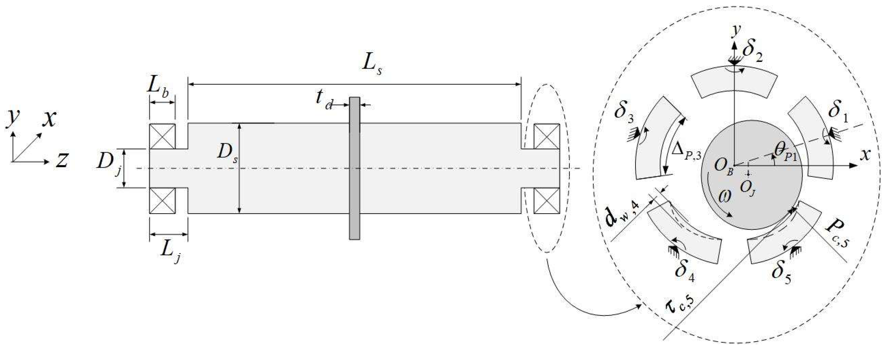
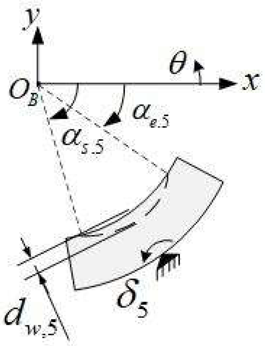
th pad is closer to the journal equilibrium position when the rotor rotates in the counter-clockwise direction, thus, forming a more severe contact with the journal. The labeling of the pads is shown in
Figure 1. The standard deviations of the roughness of both surfaces are equal to
. Intact TPJB and two worn TPJBs with different wear severities are investigated. The effect of wear severity is examined on TPJB thermal and dynamic behavior of the system. The maximum wear depth on the 5
th pad of the more severely worn TPJB is assumed to be 20μm. This TPJB is labeled as the 20μm worn bearing case in the rest of the paper. The maximum wear depth on the 5th pad of the less severely worn TPJB is equal to 10μm, and this TPJB is entitled the 10μm worn bearing case. Three speeds of 3500rpm, the first critical speed of the system, and 10200rpm are selected to show the behavior of the system in its equilibrium position. The speed of 3500rpm represents the system behavior below the first critical speed, while the velocity of 10200rpm demonstrates the system behavior in its service operating speed. The oil film thickness and the pressure distribution in the TPJB mid-line are depicted in
Figure 3 and
Figure 4, respectively. The effects of wear on the loaded pads are visible in the profile of the loaded pads oil film thicknesses (
Figure 3).
Table 2.
Rotor-tilting pad bearing properties.
Table 2.
Rotor-tilting pad bearing properties.
| Rotor |
Bearing |
| Parameter |
Value |
Parameter |
Value |
|
200Gpa |
|
0.5 |
|
|
|
125.196mm |
| N |
0.3 |
L |
50mm |
|
125mm |
|
0.3988 |
|
160mm |
|
18, 90, 162, 234, 306deg |
|
1.84m |
|
52deg |
|
0.08m |
|
|
|
176.4kg |
|
1200kg |
Table 3.
TPJB Thermal and Surface properties.
Table 3.
TPJB Thermal and Surface properties.
| Parameter |
Value |
Parameter |
Value |
|
2000J/kg/K |
|
0.05 |
|
|
|
222.31GPa |
|
|
|
0.1 |
|
0.0396Pa.s |
|
493MPa |
|
22W/m.K |
|
45W/m.K |
Figure 4a shows the cavitation on the 1
st and the 2
nd pads at 3500rpm when the maximum wear depth is 20μm. When the system speed reaches its first critical speed, and a worn bearing with 10μm or 20μm maximum wear depth is used, cavitation only occurs on the 2
nd pad (see
Figure 4b). Noteworthy, there is no cavitation on the pads if an intact bearing is used at the first critical speed of the system. Based on
Figure 4c, no cavitation can be detected when the operating speed increases to 10200rpm and an intact or 10μm worn TPJB is used; however, cavitation occurs on the 2
nd pad when a 20μm worn TPJB is utilized. The effect of cavitation on the oil film thickness is visible in
Figure 3 as well at the mentioned operating conditions. Based on
Figure 3 and
Figure 4, an increase in the wear depth of the loaded pad leads to an increase in the probability of cavitation on the unloaded pads. Furthermore, the system is more prone to cavitation at lower speeds. The probability of cavitation formation decreases as the speed increases to the operating speed of the system.
Figure 5,
Figure 6 and
Figure 7 show the effects of intact and worn TPJBs at two different wear severities on the temperature distribution of the pads at 3500rpm, the system’s first critical speed, and 10200rpm.
Figure 3.
Oil film thickness on intact and worn TPJBs. a) Shaft rotational speed is equal to 3500rpm b) Shaft rotational speed is equal to the first critical speed of the system c) Shaft rotational speed is equal to 10200rpm. (Blue solid line: Intact bearing, Red dashed line: Bearing with maximum wear depth of , Magenta dashed dot line: Bearing with maximum wear depth of .).
Figure 4.
Hydrodynamic pressure distribution on intact and worn TPJBs. a) Shaft rotational speed is equal to 3500rpm b) Shaft rotational speed is equal to the first critical speed of the system c) Shaft rotational speed is equal to 10200rpm. (Blue solid line: Intact bearing, Red dashed line: Bearing with maximum wear depth of , Magenta dashed dot line: Bearing with maximum wear depth of .).
Figure 5.
Pad temperature distribution at 3500rpm. a) Intact bearing b) Maximum wear depth: 10μm c) Maximum wear depth: 20μm.
Figure 5.
Pad temperature distribution at 3500rpm. a) Intact bearing b) Maximum wear depth: 10μm c) Maximum wear depth: 20μm.
Figure 6.
Pad temperature distribution at the first critical speed of the system. a) Intact bearing b) Maximum wear depth: 10μm c) Maximum wear depth: 20μm.
Figure 6.
Pad temperature distribution at the first critical speed of the system. a) Intact bearing b) Maximum wear depth: 10μm c) Maximum wear depth: 20μm.
Figure 7.
Pad temperature distribution at 10200rpm. a) Intact bearing b) Maximum wear depth: 10μm c) Maximum wear depth: 20μm.
Figure 7.
Pad temperature distribution at 10200rpm. a) Intact bearing b) Maximum wear depth: 10μm c) Maximum wear depth: 20μm.
Furthermore,
Figure 8 presents the inner surface temperature of the pads at 3500rpm, the first critical speed of the system, and 10200rpm. Based on Figures 5 to 7, the wear in loaded pads decremented the temperature in the unloaded pads while raising the temperature increase in the loaded ones. Furthermore, the wear-induced temperature variations of the pad are more severe at lower speeds. Considering
Figure 8, the 5
th pad, which experiences more severe wear, has a higher temperature variation near its trailing edge. Therefore, the temperature variations of the loaded pads near their trailing edges provide an accurate indicator to determine the wear severity and bearing geometrical imperfections. This indicator introduced by Lee et al. [
2] to diagnose wear in TPJB using an experimental test-rig as well.
Figure 8.
Pads inner surface temperature for intact and worn TPJBs a) Shaft rotational speed equals 3500rpm b) Shaft rotational speed equals to the first critical speed of the system c) Shaft rotational speed equals 10200rpm. (Blue solid line: Intact bearing, Red dashed line: Bearing with maximum wear depth of , Magenta dashed dot line: Bearing with maximum wear depth of .).
The effects of using intact and worn TPJBs on the temperature variations of the loaded pads near their trailing edges are shown in
Figure 9a and b for a range of shaft rotational speeds. The temperature of a point on the pad surface at the distance of 71% of the arc length of the pad from its leading edge is shown in these figures. This point on loaded pads is appropriate for temperature measurement using probes in experimental and industrial studies as it is near the trailing edge of the pad and experiences more temperature variations due to wear. It should be noted that the 5
th pad temperature rises more significantly than the 4
th pad because the 5
th pad is closer to the journal equilibrium position in this simulation. Furthermore, the wear-induced pad temperature rise is more significant at low speeds and slightly decreases by increasing the shaft speed since the rotor rotates closer to the loaded pads at lower speeds. Based on the results, it is recommended to measure the temperature of the loaded pads near their trailing edges at lower speeds in a balanced rotor-TPJB system to detect the bearing wear. The effect of wear of the loaded pads on the journal eccentricity is also illustrated in
Figure 9c. As seen, an increase in the wear depth of the pads raises the journal eccentricity.
It is worth mentioning that the variations in the lubricant temperature will change the lubricant viscosity, which affects the dynamic coefficients of the system. Here, the TPJB dynamic coefficients are obtained considering the geometrical imperfections of the pads based on the procedure presented in [
41].
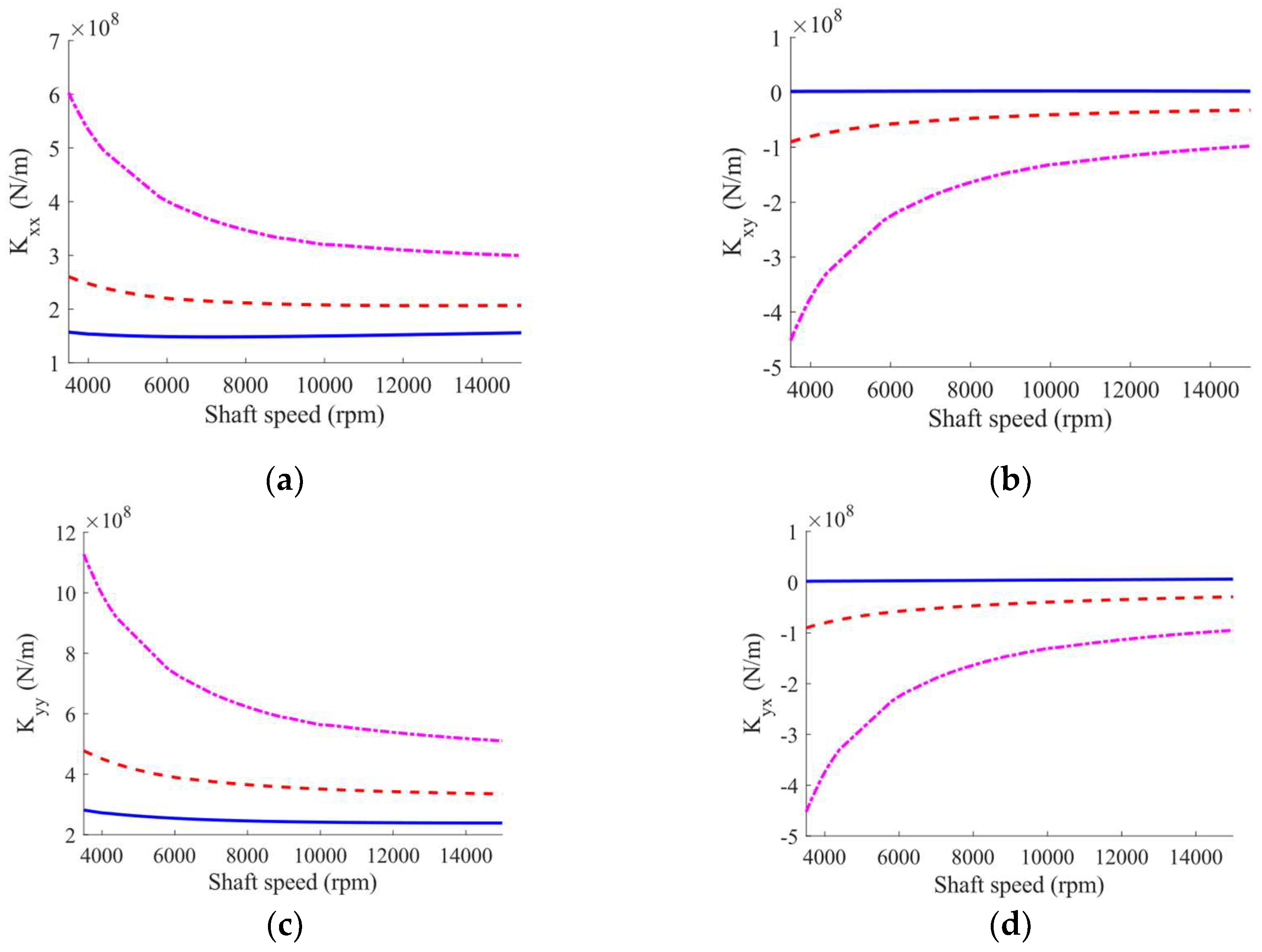
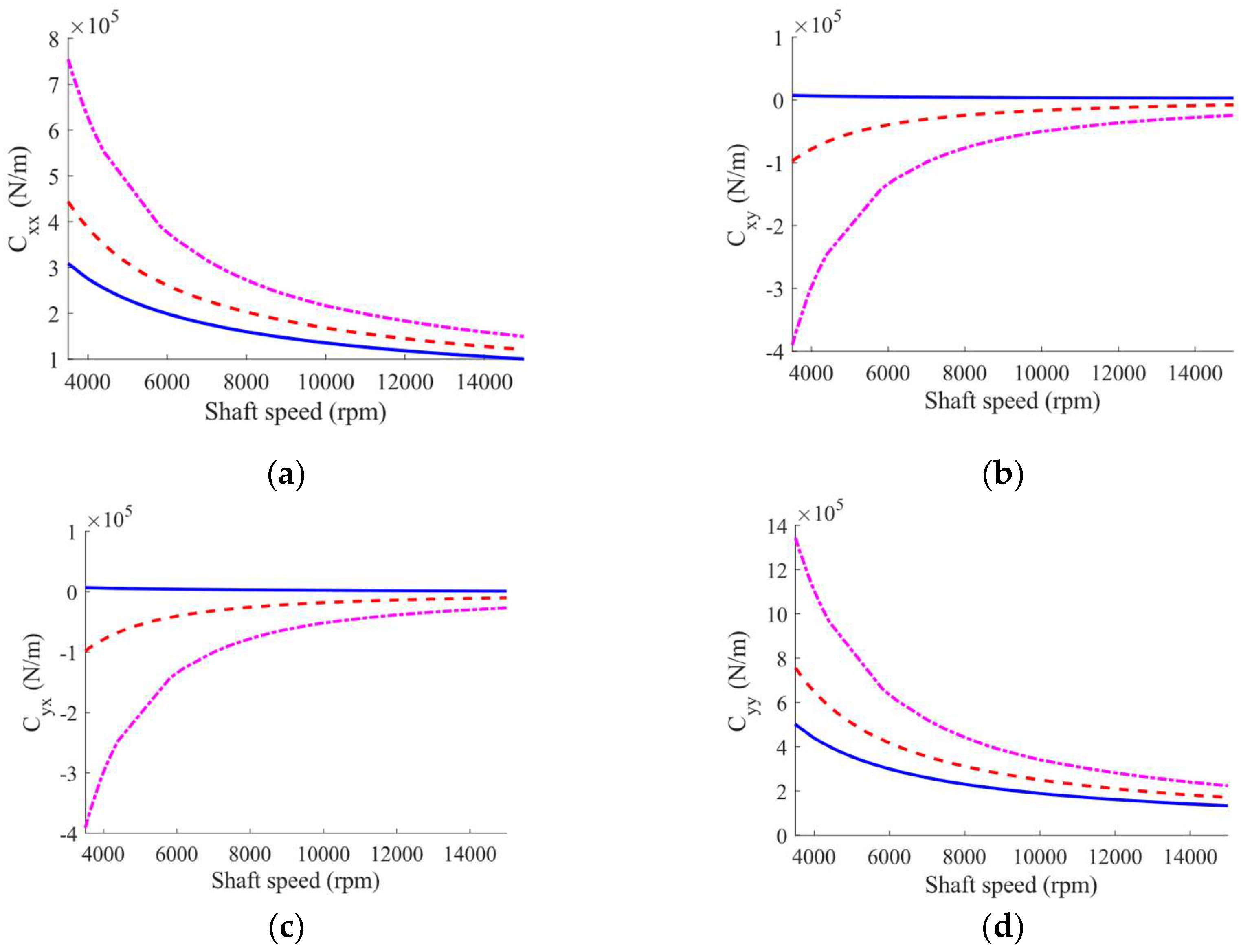
Figure 10 and
Figure 11 shows the changes in the dynamic coefficients of the intact and worn bearings versus the shaft rotating speeds. Accordingly, the dynamic coefficients of the bearing show less sensitivity to geometrical imperfections at higher speeds. This phenomenon can be assigned to the formation of a thicker oil film at higher shaft speed, therefore, the rotor rotates farther than the loaded pads.
Furthermore, an increase in the wear severity leads to the creation of the cross-coupling terms of the TPJB stiffness and damping coefficients which can affect the system stability. However, an increase in the sleeve bearing wear severity can lead to decrease in bearing stiffness [
45], according to
Figure 10 and
Figure 11, the increase in the wear severity in TPJBs with load between pads (LBP) configuration results in an increase in direct dynamic coefficients due to the enhancement of the wear-induced asymmetry and preload of the TPJBs. The increase in TPJBs dynamic coefficients with LBP configuration due to the bearing preload and bearing asymmetry enhancement was also discussed in [
5,
46,
47].
Figure 9.
The effect of wear in loaded pads considering variable shaft speed a) Pad number 4 temperature in 71% of the pad’s arc length from its leading-edge b) Pad number 5 temperature in 71% of the pad’s arc length from its leading-edge. c) Journal eccentricity (Blue solid line: Intact bearing, Red dashed line: Bearing with maximum wear depth of , Magenta dashed dot line: Bearing with maximum wear depth of .).
Figure 10.
TPJB stiffness for intact and worn bearings cases at different speeds (Blue solid line: Intact bearing, Red dashed line: Bearing with maximum wear depth of , Magenta dashed dot line: Bearing with maximum wear depth of .).
Figure 10.
TPJB stiffness for intact and worn bearings cases at different speeds (Blue solid line: Intact bearing, Red dashed line: Bearing with maximum wear depth of , Magenta dashed dot line: Bearing with maximum wear depth of .).
Figure 11.
TPJB damping for intact and worn bearings cases at different speeds (Blue solid line: Intact bearing, Red dashed line: Bearing with maximum wear depth of , Magenta dashed dot line: Bearing with maximum wear depth of .).
Figure 11.
TPJB damping for intact and worn bearings cases at different speeds (Blue solid line: Intact bearing, Red dashed line: Bearing with maximum wear depth of , Magenta dashed dot line: Bearing with maximum wear depth of .).
In the proposed model, flexible rotor vibration amplitudes are obtained at the disc and the journal locations using the calculated dynamic coefficients as shown in
Figure 12. As seen, an increase in the wear severity of loaded pads of TPJB with LBP configuration, increases the vibration amplitude of the rotor at its mid-point at the critical speed of the system. Moreover, an increase in wear on loaded pads causes a shift in the first critical speed of the system. Changes in the first critical speed of the system and the rotor vibration amplitude induced by the bearing wear are quantitatively shown in Table. 4. According to this table, the system’s first critical speed value and its vibration amplitude are good indicators of wear severity in TPJBs at its early stages.
Figure 12.
Rotor vibration amplitudes for intact and worn TPJBs considering mass unbalance on disc a) Disc vibration amplitude b) Journal vibration amplitude (Blue solid line: Intact bearing, Red dashed line: Bearing with maximum wear depth of , Magenta dashed dot line: Bearing with maximum wear depth of .).
Table 4.
The effect of the bearing wear severity on the rotor-TPJB first critical speed and the variation of the rotor’s vibration amplitude.
Table 4.
The effect of the bearing wear severity on the rotor-TPJB first critical speed and the variation of the rotor’s vibration amplitude.
| Maximum wear depth |
First critical speed |
Increase in vibration amplitude of the journal |
Increase in vibration amplitude of the disc |
| Intact bearing |
5500rpm |
- |
- |
|
6200rpm |
23.7% |
47.2% |
|
6900rpm |
52.6% |
253.3% |
In the next part of the paper, it is assumed that the disc has a 0.04 kg.m unbalanced mass. Therefore, the rotor orbits around its equilibrium position at the steady state. In such conditions, the contact between the journal and the bearing is possible due to the high vibration level of the rotor, possibility of fluttering of unloaded pads, and the wear-induced geometrical imperfections of the loaded pads.
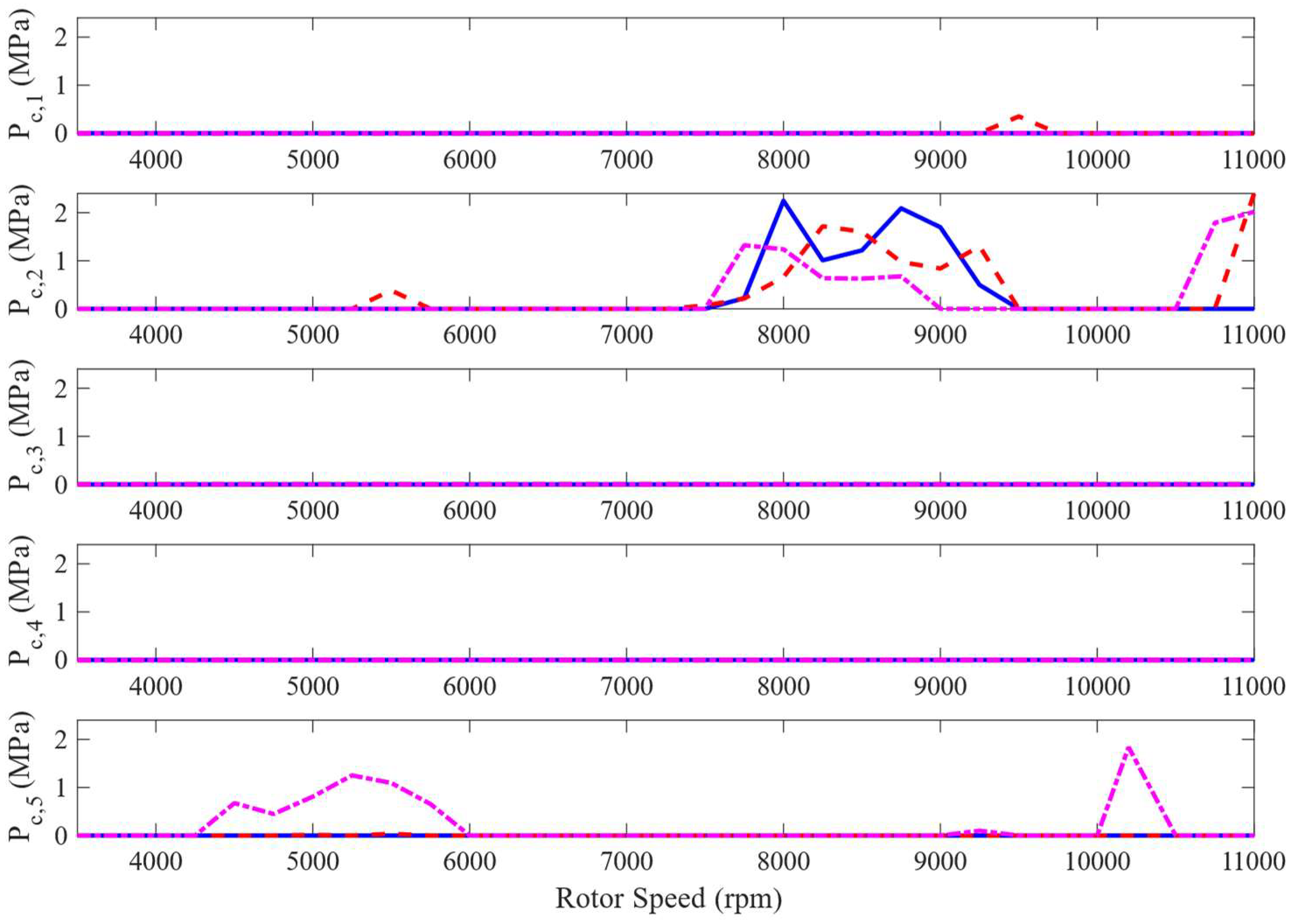
Figure 13 and
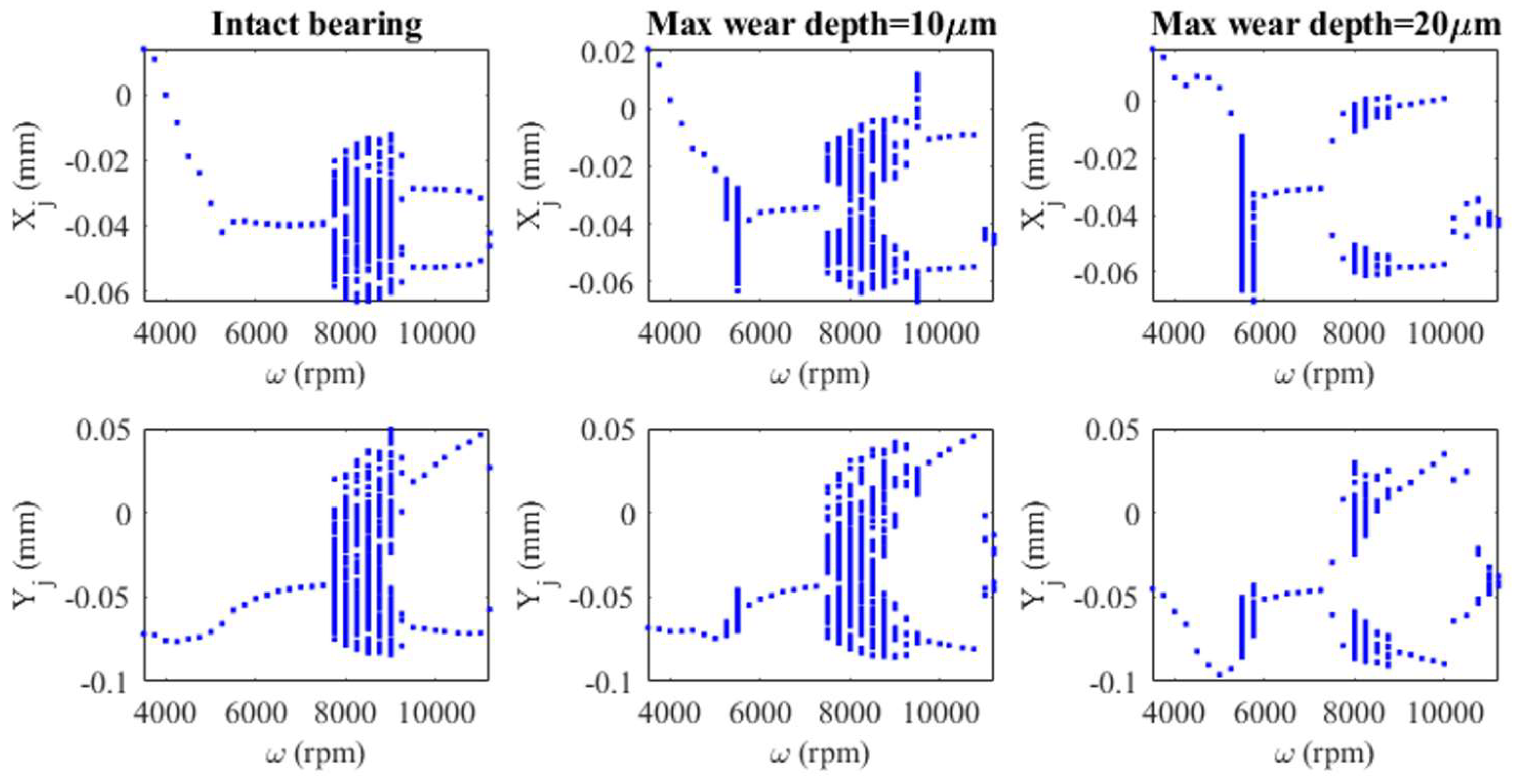
Figure 14 show the solid-to-solid contact pressure induced by the rub-impact between the journal and the pads at different speeds and bifurcation diagrams for the journal center in horizontal and vertical directions. Based on
Figure 14, the rotor motion is period one for the intact bearing at the speeds of 3500-7500rpm and
Figure 13, shows no contact between the journal and the pads for intact bearing case in the mentioned speed range. According to
Figure 13, contact occurs between the unbalanced rotor and the 2
nd pad when there is a wear signature on the loaded pads with a maximum wear depth of 10μm in the shaft speed range of 5250-5500rpm. Since the 2
nd pad is unloaded, the contact occurs due to pad flutter. Moreover, the rotor motion changes to irregular patterns at the mentioned speed range and then returns to period one based on
Figure 14. The effect of pad fluttering on a rotor-TPJB dynamic behavior and the rotor irregular motion induced by pad fluttering was studied in previous works [
48] using bifurcation diagrams.
When wear depth increases to 20μm, contact between the journal and the 5
th pad of the bearing starts from 4500 rpm and increases with the rotor speed until reaching its maximum severity at 5250 rpm. Contact pressure decreases beyond this speed, and vanishes at 6000rpm. The 5
th pad is a loaded pad and the mentioned journal-bearing contact is induced by the wear signature on this pad. For this case, Figure14 shows irregular rotor motion in the speed range of 5250 to 5750rpm where the obtained vibration amplitude is larger than the 10μm worn bearing case at the same speed range. Based on
Figure 13, the contact between the journal and the unloaded pad vanishes when the maximum wear depth increases to 20μm; but contact between the journal and the loaded pad becomes more severe than the 10μm worn bearing case. Since an increase in loaded pad wear depth changes the journal orbit location to a lower position in the bearing, the increase in the bearing wear severity decreases the probability of contact between the journal and upper pads while increasing the rub-impact between the journal and the lower pads.
As shown in
Figure 12, the increase in vibration amplitude in the mentioned speed range is due to the first critical speed of the rotor. In this situation, the rotor rotates near the bearing due to its low speed, and journal-bearing contact is arisen from its high mass unbalance. These observations conclude that the increase in wear depth in loaded pads makes the rotor-bearing system more prone to experience an increase in wear and rub-impact near the first critical speed of the system.
Figure 13.
Solid-to-solid contact pressure induced by journal-bearing contact at different speeds for pad No. 1 to pad No. 5 in the intact and worn bearing cases (Blue solid line: Intact bearing, Red dashed line: Bearing with maximum wear depth of , Magenta dashed dot line: Bearing with maximum wear depth of .).
Figure 14.
The journal displacement bifurcation diagrams in different speeds for the intact and the worn bearing cases.
Figure 14.
The journal displacement bifurcation diagrams in different speeds for the intact and the worn bearing cases.
By enhancing the rotor speed, the rotor rotates nearer to the bearing center and the oil film forms to separate the journal and the bearing. Based on
Figure 13, there will be no contact between the journal and the bearing in the speed range of 5750-7500rpm for an intact and a 10μm worn bearing case. For the 20μm worn bearing case, no contact is expected in the speed range of 6000 to 7500 rpm. The period one motion of the rotor is visible from
Figure 14 for the speed range of 5750-7500rpm. Journal-bearing contact starts again at 7500rpm for all intact and worn bearing cases. According to
Figure 13, this contact occurs between the journal and the 2
nd pad which is an unloaded pad. This phenomenon is due to the high mass unbalance of the rotor and the unloaded pad flutter.
Figure 13 also suggests that the rotor experiences a lower contact pressure between the journal and the upper pad during pad fluttering in the mentioned speed range as the wear depth on loaded pads increases. Such a trend can be assigned to the lower orbit position of rotor in a worn TPJB, which decreases the contact between the journal and the upper pads.
Figure 13 and
Figure 14 show that the rotor motion changes to period two and the contact pressure vanishes at higher speeds.
Figure 13 shows that the rotor-intact TPJB operates without journal-bearing contact in the speed range of 7500-11000rpm, suggesting that the unbalanced rotor-intact TPJB can work without rub-impact at its service speed (10200rpm). The journal-worn bearing contact starts again at 10200rpm for the 20μm worn bearing case which is induced by the contact between the journal and the 5
th pad (see
Figure 13). Furthermore, the contact between journal and the upper pad appears again at 10500 and 10750 rpm for the 10μm worn bearing and the 20μm worn bearing cases, respectively. Based on
Figure 13 and
Figure 14, the journal-intact bearing has much better dynamic behavior than a worn TPJB at 10200rpm (the standard operating speed of the system). Furthermore, an increment in wear of the loaded pads increases the journal-bearing rub-impact and promotes the irregular dynamic motion around the service speed of the system.
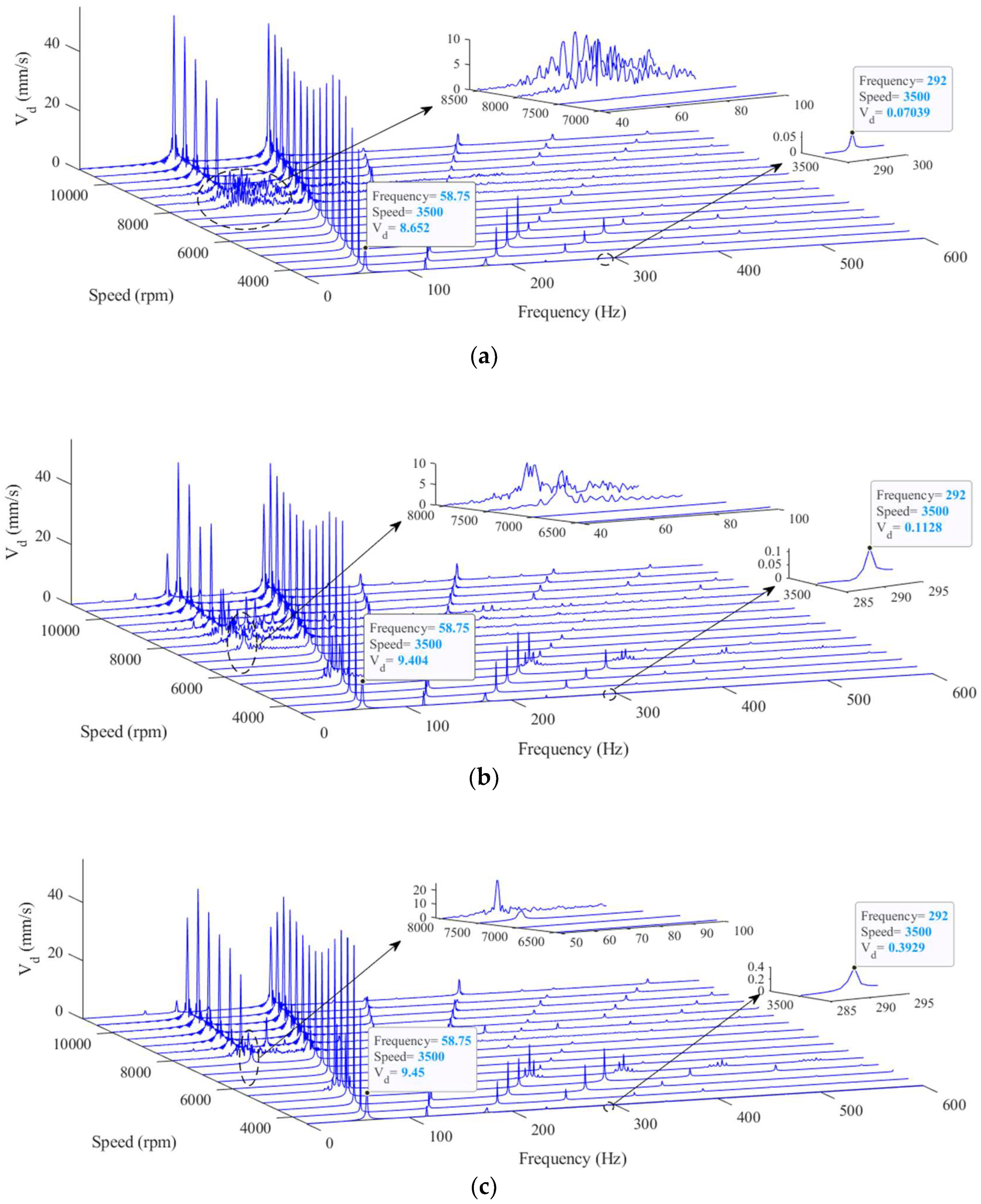
Waterfall diagrams for the intact and the worn bearing cases are illustrated in
Figure 15a-c. The effects of oil whirl which is induced by the oil film nonlinear force [
49] are recognizable in these diagrams. Note that the frequency of the oil whirl equals half of the rotational frequency of the journal. Moreover, the oil whip has a constant frequency that approximately equals the first critical speed of the system [
50]. The zoomed plots in
Figure 15a-c present the speeds at which the oil whirl effect starts to appear in the system frequency response. The velocity signal amplitude is also depicted for 1X and 5X frequency component at the shaft speed of 3500rpm. Based on
Figure 15a, the oil whirl starts at 8000rpm, and its amplitude increases at 9000rpm for the case of the intact bearing. For both 10μm and 20μm worn bearing cases, oil whirl effects appear sooner at 7500rpm (
Figure 15b,c). Therefore, the minor wear in loaded pads of the TPJB with LBP configuration can lead to the oil whirl at a slightly lower speed compared to the intact TPJBs.
Since the rotor rotates closer to the loaded pads at the lower speeds, the signals of the system motion at low speeds can better show the effects of the geometrical imperfections of the hydrodynamic bearing [
21]. Therefore, the peak amplitudes of the velocity signal are investigated at three speeds of 3500rpm, the first critical speed of the system, and 10200rpm. It is worth mentioning that 3500rpm represents one of the sub-critical speeds, while the operating speed of the system is 10200rpm. The mentioned values are chosen for the shaft speed to compare the intact and worn TPJB velocity signal peak amplitudes to analyze the effects of the geometrical imperfections of the loaded pads on the dynamic motion of the system.
Figure 15.
Waterfall diagrams for disc velocity in a range of rotor speeds and different wear severities, a) Intact bearing b) Maximum wear depth: 10μm c) Maximum wear depth: 20μm.
Figure 15.
Waterfall diagrams for disc velocity in a range of rotor speeds and different wear severities, a) Intact bearing b) Maximum wear depth: 10μm c) Maximum wear depth: 20μm.
Table 5 lists the amplitudes of the disc velocity signal peaks at 3500rpm. Furthermore, the peak amplitudes of 1X and 5X frequency components are depicted in Figure15a-c for the mentioned signals. According to
Figure 15a-c and
Table 5, an increase in maximum wear depth of the bearing enhances the 1X harmonic component of the velocity signal. Moreover, the increase in wear depth increments in the disc velocity signals of the 5X, 6X, and 7X components. The experimental observations in [
32] also show similar behavior for the frequency response of a worn TPJB velocity signal at low speeds. Therefore, 1X, 5X, and higher harmonic components of the shaft velocity signal at low speeds provide an accurate indicator for detecting the wear severity of the bearing at its early stages.
Table 6 and
Table 7 show the amplitude of the disc velocity signal at the first critical speed of the system and 10200rpm (i.e. operating speed of the system). Furthermore, the TPJB system experiences the oil whirl at 10200rpm. The whirl amplitudes at 0.5X frequency components are shown in
Table 7. Since an increase in the shaft speed shifts the journal equilibrium position toward the bearing center, the journal rotates in a farther place relative to the worn pads at higher speeds. Therefore, the geometrical imperfections of the bearing have a more negligible effect on the dynamics of the system, and the peak amplitudes of the velocity signal cannot be used for wear detection at this speed.
The effects of wear-induced geometrical imperfections of the bearing on the variations of the velocity signal peak amplitudes are shown in
Table 8 at 3500rpm and the first critical speed of the system. According to this table, the velocity signals of 1X and 5X harmonic components are good indicators to detect wear in the loaded part of the TPJB.
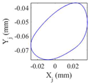
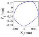
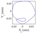
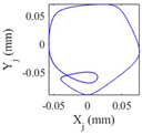
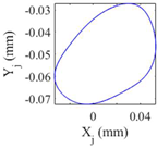
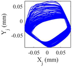
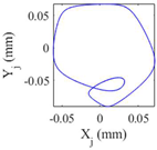
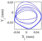
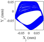
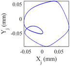
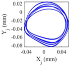
Table 9 presents the journal center orbit diagrams at 3500, 5500, 10200, and 11000rpm. These results are shown for the intact and two worn bearing cases with a maximum wear depth of 10μm and 20μm, respectively. According to
Figure 12, the 5500rpm is the first critical speed of the rotor-intact TPJB system. Furthermore, the standard operating speed of the system equals to 10200, hence, the speed of 11000rpm exceeds the standard operating speed of the system. Based on
Table 9, the wear in loaded pads changes the periodic motion of the rotor to irregular motion. Furthermore, TPJB keeps its period two motion at 10200rpm when a bearing with 10μm maximum wear depth is used. But if the maximum wear depth increases to 20μm, the system behavior changes to the irregular motion. It is worth mentioning that 10μm wear depth changes the system behavior from period two to period six motion at the speed of 11000rpm.
Table 5.
Peak amplitudes of the disc velocity signal spectra at 3500rpm in mm/s.
Table 5.
Peak amplitudes of the disc velocity signal spectra at 3500rpm in mm/s.
| |
1X |
2X |
3X |
4X |
5X |
6X |
7X |
| Intact bearing |
8.652 |
4.064 |
2.604 |
0.7275 |
0.07039 |
0.09018 |
0.01463 |
| 10μm wear depth |
9.404 |
4.955 |
3.166 |
0.9615 |
0.1128 |
0.1643 |
0.02591 |
| 20μm wear depth |
9.45 |
3.683 |
1.88 |
0.917 |
0.3929 |
0.3704 |
0.0915 |
Table 6.
Peak amplitudes of the disc velocity signal spectra at the first critical speed of the system in mm/s.
Table 6.
Peak amplitudes of the disc velocity signal spectra at the first critical speed of the system in mm/s.
| |
1X |
2X |
3X |
4X |
5X |
6X |
7X |
| Intact bearing |
52.04 |
8.922 |
14.81 |
5.486 |
0.8825 |
0.8505 |
0.3522 |
| 10μm wear depth |
53.55 |
8.032 |
11.41 |
3.837 |
1.534 |
0.3031 |
0.2553 |
| 20μm wear depth |
62.89 |
6.998 |
11.78 |
6.383 |
2.414 |
1.044 |
0.4888 |
Table 7.
Peak amplitudes of the disc velocity signal spectra at 10200rpm in mm/s.
Table 7.
Peak amplitudes of the disc velocity signal spectra at 10200rpm in mm/s.
| |
0.5X |
1X |
1.5X |
2X |
2.5X |
3X |
3.5X |
| Intact bearing |
42.43 |
43.23 |
2.685 |
3.005 |
1.56 |
1.338 |
0.503 |
| 10μm wear depth |
44.77 |
44.59 |
2.972 |
3.788 |
2.232 |
1.568 |
0.8926 |
| 20μm wear depth |
34.39 |
35.3 |
4.073 |
0.9427 |
1.785 |
1.68 |
0.9641 |
Table 8.
Effect of wear severity on disc vibration amplitude at 3500rpm and the first critical speed.
Table 8.
Effect of wear severity on disc vibration amplitude at 3500rpm and the first critical speed.
| Maximum wear depth |
Rotor speed |
Increase in 1X Vibration amplitude |
Increase in 5X Vibration amplitude |
|
3500rpm |
8.6% |
160% |
| First critical speed (6200rpm) |
2.9% |
73% |
|
3500rpm |
9.2% |
558% |
| First critical speed (6900rpm) |
20.8% |
273% |
Table 9.
Journal orbits in selected rotational speeds for intact and worn bearing cases.
To sum up, the increase in the wear severity of the bearing is detectable by analyzing the dynamic behavior of the system as well as the temperature trend of the pads. This paper shows that the temperature of the loaded pads near their trailing edges and 1X, 5X, and higher harmonic components of the disc velocity signal are suitable indicators for detecting TPJBs wear severity at the early stages. Furthermore, wear on the loaded pads negatively affects the dynamic behavior of the system at low, middle, and standard operating speeds.
