1. INTRODUCTION
With the increasing importance of global greenhouse gas emissions and climate warming, the energy conservation and emission reduction of HVAC have been paid more and more attention by the relevant national departments and industries, which also put forward higher requirements for air conditioning accessories. The four-way reversing valves are the main component of the air conditioning system, which is mainly used in the heat pump type air conditioning unit. Through the four-way reversing valve, the air conditioning system can realize the conversion of refrigerant flow direction according to the needs, and change the functions of the condenser and evaporator of the air conditioning system, so as to realize the switch of the refrigeration, heating, defrosting and other functions of the air conditioner.
Researchers have done a lot of work on the characteristics of air conditioner four-way reversing valves [
1,
2,
3,
4]. Krishnan [
5] evaluated the impact of the four-way reversing valves on the performance of the heat pump air-conditioning system and pointed out that the poor performance of the four-way reversing valves could lead to a 5% reduction in the efficiency of the whole system. Damasceno [
6] discussed the influence of the four-way reversing valves on the heat pump air conditioning system through a mathematical model in terms of heat transfer, pressure drop and leakage. Raichintala and Kulkarni [
7] also established a mathematical model of the four-way reversing valves to describe the energy loss of the valves and its influence on the heat pump system. In this mathematical model, energy loss caused by friction, refrigerant leakage and heat transfer was separated from the total energy loss and each factor was investigated separately. Deng [
8] studied and compared the performance of the heat pump system with and without four-way reversing valves by using experimental methods, and the results showed that the heating capacity, performance coefficient (COP) and energy efficiency of the heat pump system without four-way reversing valves were improved. Chen [
9] analyzed the two basic conditions for reversing smoothly of four-way reversing valves from theoretical and experimental perspectives. Liu [
10] studied the influence of the flow channel on the flow performance of the four-way reversing valves through simulation and experiment. Peng [
11] compared and analyzed the performance of the traditional four-way reversing valves structure and D-E straight-through four-way reversing valves, and the results showed that D-E straight-through four-way reversing valves could improve the heating performance of the system, but could not improve the annual energy consumption efficiency of the air-conditioning system APF (Annual Performance Factor).
In the early stage, researchers conducted many studies on the impact of four-way reversing valves on energy efficiency, heat transfer and leakage of the whole air conditioning system, but rarely involved research on the reversing performance of four-way reversing valves [
12,
13]. As the slider is the main part of the four-way reversing valves, the research on the reversing performance of the slide block to the four-way reversing valve is not comprehensive enough.
In this paper, the internal flow field of four-way reversing valves with different sliders and its influence on the reversing performance are studied by means of numerical analysis. It is found that the slider structure of the four-way reversing valves can cause changes in the flow field inside the chamber, and by comparing the resistance and thrust of different slider structures, it is found that the cutting-structure slider valves are effective in improving the reversing smoothness. The research results of this paper can provide a reference for the optimized design of the four-way reversing valves. It can be of important significance to improve the smoothness of reversing during the operation of air conditioners.
2. Structure and principle of four-way reversing valve
2.1. Structure of four-way reversing valve
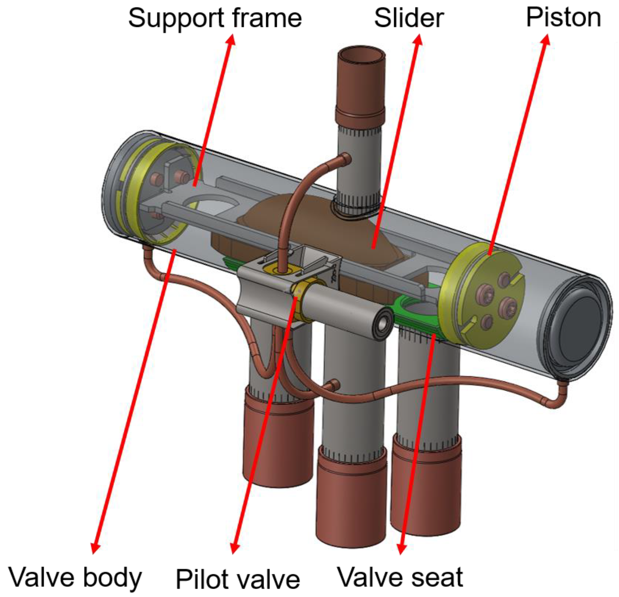
The four-way reversing valve is a complex component in the air conditioning system, which is mainly composed of slider, valve seat, valve body, pilot valve, piston, slider support frame and tubes connecting the inlet and outlet of the compressor and the two units of the air conditioning system (evaporator and condenser), as shown in
Figure 1. A slider embedded in the support frame changes the refrigerant flow direction from one end of the valve chamber to the other.
2.2. Working principle of four way reversing valve
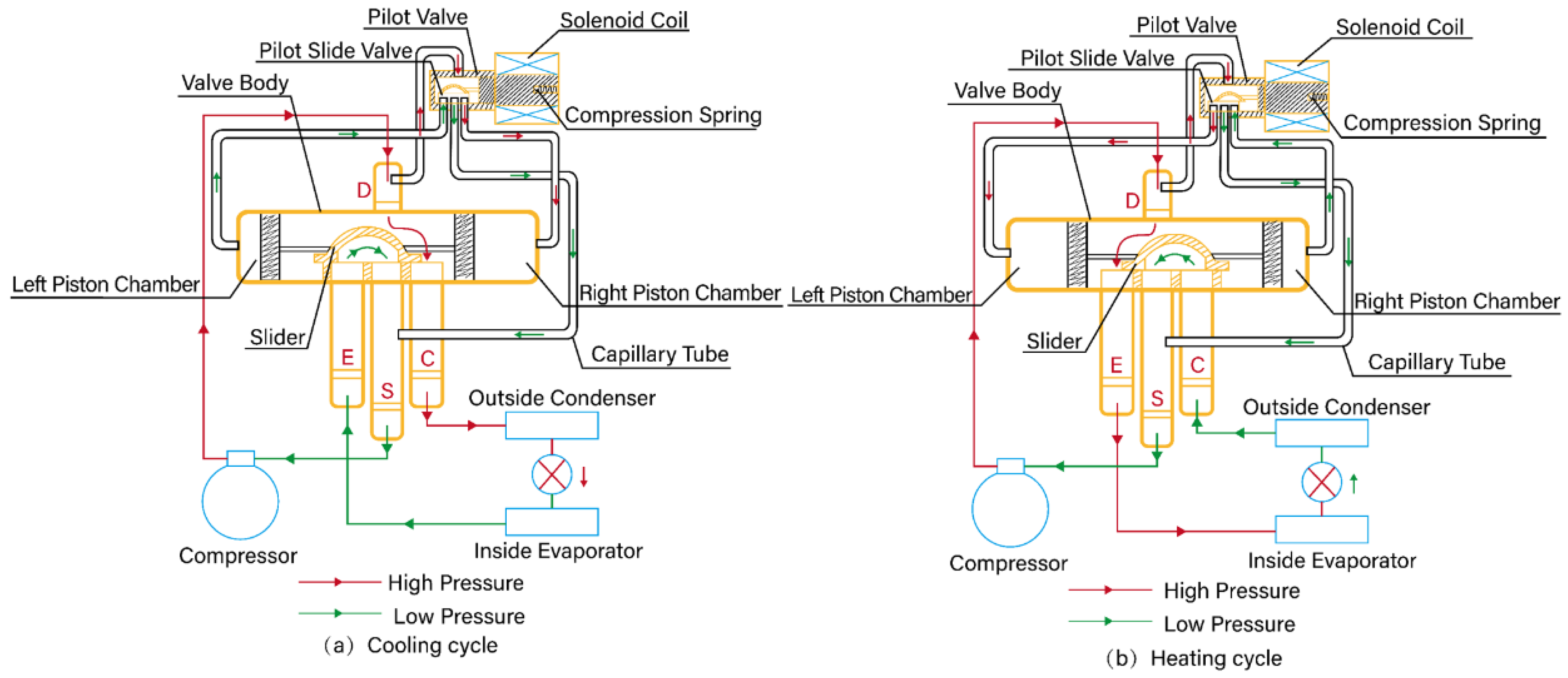
The working principle of the four-way reversing valve is shown in
Figure 2. When the heat pump air-conditioning system switches from the heating cycle shown in
Figure 2 (b) to the cooling cycle shown in
Figure 2 (a), the electromagnetic coil is powered off, the pilot slide valve moves to the left driven by the compression spring force, and the high-pressure refrigerant gas enters the right piston chamber through the pilot valve. At the other end, the compressor continuously draws gas into the compressor through the S-tube, reducing the pressure in the left piston chamber. At this time, there is a pressure difference between the piston chambers, thus moving the slider to the left. When the slider moves to the left end position, the E/S tube and the D/C tube are connected respectively, and the heat pump system switches from the heating cycle to the cooling cycle.
When the electromagnetic coil is energized, the electromagnetic force generated by the electromagnetic coil in the pilot valve moves to the right to overcome the tension of the spring, and the high-pressure refrigerant gas enters the left piston chamber through the pilot valve. At the other end, the compressor constantly draws gas into the compressor through the S-tube, reducing the pressure in the right piston chamber. At this time, there is a pressure difference between the left and right piston chambers, thus moving the slider to the right. When the slider moves to the right end position, the C/S tube and the D/E tube are connected respectively, and the heat pump system switches from the cooling cycle to the heating cycle.
3. Hydrodynamic control equations
Computational fluid dynamics (CFD) is the process of dividing the continuum model of air moving into large algebraic equations and solving them on a computer. The partial differential equation is transformed into algebraic equation by discretization and algebraic differential equation, and then the equations are solved by appropriate numerical calculation method to obtain the numerical solution of the flow field, and then the node solution is fitted to the corresponding area of the grid by different fitting methods. With the development of computational fluid dynamics and the improvement of computer running speed, computational fluid dynamics has been used by more and more researchers to study the flow field inside the valve, in order to obtain the detailed situation of fluid flow inside the valve [
14,
15,
16,
17].
When fluid flows, all media satisfy the law of conservation of physics: the law of conservation of mass, momentum and energy. When the fluid flow is in turbulent state, the whole system also follows the turbulent transport equation. These mathematical descriptions of conservation laws are collectively known as governing equations. In this paper, the Realizable k-ε turbulence model provided in CFD software is used for numerical calculation.
The control equation of turbulence is three-dimensional incompressible Reynolds time-mean Navier-Stokes equation:
Where div is vector symbol, div(a)= ∂ax/∂x+∂ay/∂y+∂az/∂z, ρ is fluid density, kg/m³; t is time,s; u is velocity vector, m/s.
Momentum conservation equation:
Where u, v, w are the components of the velocity vector u in the x, y, and z directions, m/s; x,y,z is fluid flow direction ; p is the pressure on a fluid cell, N; τ is viscous stress, Pa; Fx, Fy,Fz is the physical strength of the micro element in the x, y and z directions, N.
Where
T is temperature, K;
k is heat transfer coefficient of fluid,W/(m
2·K);
cp is specific heat capacity of fluid, J/(kg·K);
ST is the internal heat source of fluid and the part of fluid mechanical energy acted by viscosity, J [
18,
19].
4. Simulation model and boundary conditions
The four-way reversing valves are located at the exhaust end of the air conditioning compressor. The four-way reversing valves realize the reversing (slider thrust) by pushing the slider in the valve body through the high temperature and high-pressure refrigerant gas from the compressor. At the same time, the slider is also under the pressure of the upper part of the high-pressure tube to achieve the fit between the valve seat (slider resistance). The easier the reversing, the resistance to push ratio is too large, which will cause poor reversing of the four-way reversing valve, which will cause vibration and noise problems of the valve body, and then affect the performance and life of the whole air conditioning. Therefore, the research on the structure of the slide block of the four-way reversing valve and the flow field in the valve body, especially the research on the pressure and velocity of the refrigerant gas near the slide block in the reversing process, has been paid more and more attention by people and become one of the research directions of the four-way reversing valve.
4.1. Simulation model
The slider is one of the core components of the four-way reversing valves, which mainly has two functions: one is to switch the flow direction of the refrigerant when the four-way reversing valves are switched over in the cooling and heating cycle; the other is to isolate the high and low pressure area in the non-reversing stable state. In the process of slider moving from one end to the other end, there is a period of time between C tube, E tube and S tube is ventilated. When the slider is in the middle position, the flow between C/E/S tube is called the middle flow, which plays the role of pressure relief. Whether the design of intermediate flow is reasonable or not directly determines the reversing performance of four-way reversing valves. If the intermediate flow rate is too small, the refrigerant pressure in the valve body will rise instantaneously and impact the slider, the friction resistance of the slider will increase, and the vibration and noise of the valve body will be produced at the same time. Excessive intermediate flow will lead to small pressure difference in the piston chamber, insufficient thrust, reversing stagnation, affecting the normal reversing function of the four-way reversing valve. The structure of the slider directly affects the intermediate flow of the four-way reversing valves, so it is necessary to design a slider with appropriate thrust and friction resistance structure to ensure the reversing performance of the four-way reversing valves.
Since the structure and size of the slider are the main factors affecting the intermediate flow rate, the no-cutting, straight- cutting and arc-cutting slider structures are selected to analyze the reversing working process, observe the changes in fluid pressure and speed in the valve chamber, as well as the changes in the resistance and thrust received by the slider, and then analyze and compare the reversing performance of the four-way reversing valve. The specific structure is shown in
Figure 3.
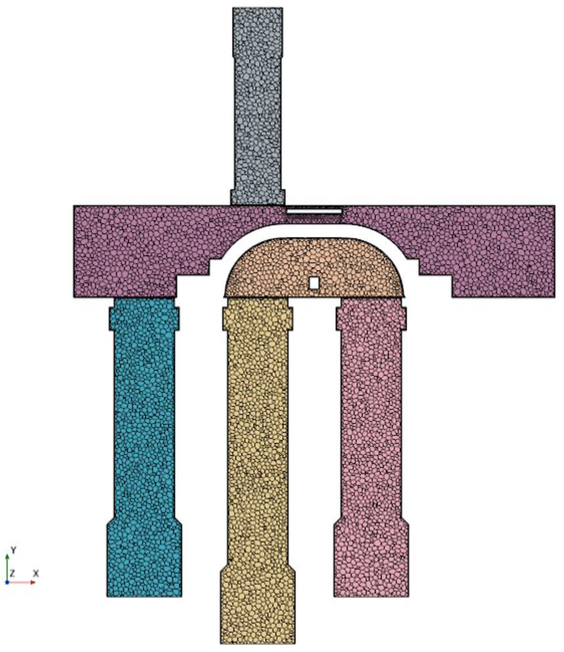
The refrigerant gas flow area such as valve body, slider, valve seat and C/E/S/D tube is taken as the calculation domain, while some non-essential parts such as capillary and pilot valve are ignored
Figure 4 shows the grid cross-section diagram of the calculation model. The calculated flow medium is common refrigerant R410A, and the corresponding thermal and physical parameters are obtained from the NISTREFPROP software. The turbulence model with Realizable k-ε Reynolds mean stress Navier-Stokes equations are addressed, which has the characteristics of high precision and low consumption of computing resources. The main advantage of polyhedral mesh is that it has multiple adjacent cells to reduce the total number of grids, and the calculation accuracy can be well guaranteed. In order to simulate the sliding process of slider, the sliding grid technique is adopted.
4.2. Boundary conditions
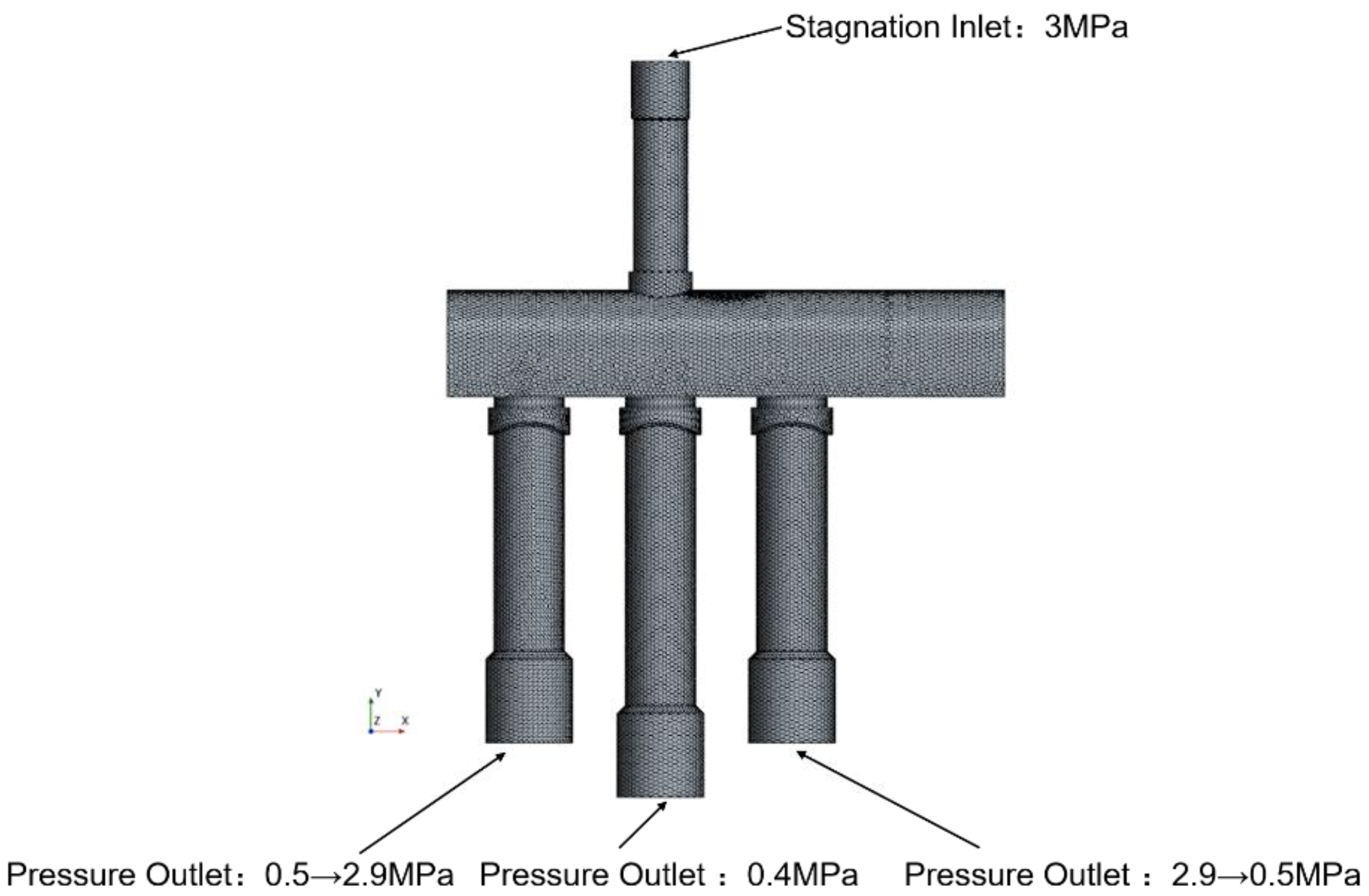
In order to ensure the consistency between the numerical simulation and the actual system, the geometric model, boundary conditions and reversing time are measured from the actual product operation. The E tube and C tube are the pressure outlet boundary. The pressure of C tube is slowly reduced from 2.9Mpa to 0.5Mpa by using dynamic function, and the pressure of E tube is slowly increased from 0.5Mpa to 2.9Mpa. The D inlet tube is set at the stagnation inlet boundary of 3.0Mpa atmospheric pressure. The outlet tube S is set as the outlet boundary condition of 0.4Mpa atmospheric pressure, and the other wall boundary is set as solid wall surface, as shown in
Figure 5. In order to ensure rapid convergence and calculation speed, the time step is set to 5×10⁻⁵s. The simulation process is from cooling cycle to heating cycle, that is, the slider slides from E tube to C tube.
5. Results and discussion
5.1. Analysis of simulation results
The slider structure determines the intermediate flow of the four-way reversing valves, and then affects its reversing fluent performance. The intermediate flow also affects the pressure and velocity of the refrigerant fluid in the valve body.
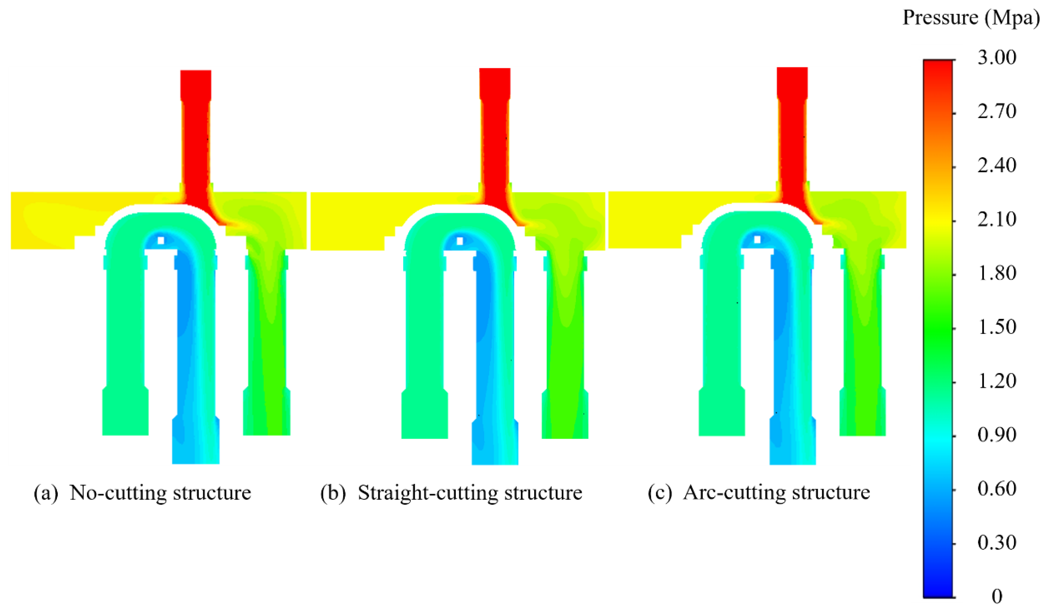
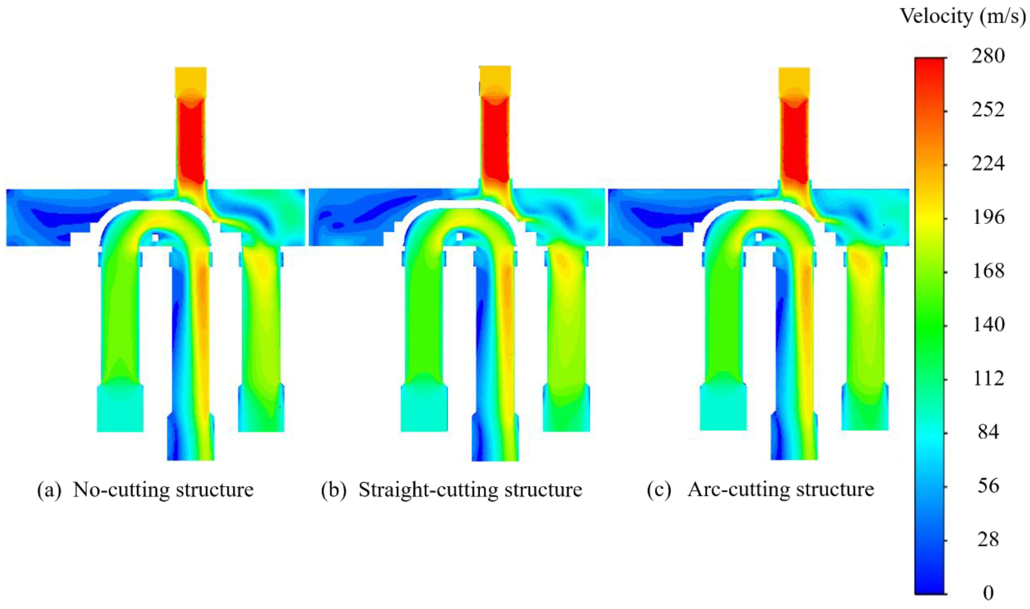
In the case of three different slider structures, the distribution of flow field pressure and velocity of refrigerant fluid in the four-way reversing valves chamber are shown in
Figure 6 and
Figure 7 when the slider is under the initial sliding state.
As can be seen from
Figure 6, the pressure value, distribution of high and low pressure areas, and pressure drop areas in the valve chamber of the different sliders are basically the same. After the high-pressure fluid is discharged from the compressor, it enters the valve body from the D tube, and then flows out to the two devices (condenser and evaporator) through the C tube, enters the E tube, and then enters the compressor to the next cycle through the S tube. The pressure distribution trend of the three structures also conforms to the above circulation process. The fluid pressure in the D tube is higher, and after entering the valve chamber, the fluid flows to both ends of the slider. On the left side of the chamber, the pressure is higher because the space is closed. E tube and S tube are connected, belonging to the low-pressure side. Fluid flows from E tube to S tube. Because the direction of fluid changes 180° near the slide block, certain pressure drop is generated. For the three slider structures, the overall pressure distribution in the four-way reversing valves is as follows: D tube has the highest pressure. After entering the main chamber, the pressure far away from the port of the connecting two devices is higher, while the pressure near the port of the connecting two devices is lower. There is no significant difference in the pressure on the surface of the slider.
As can be seen from
Figure 7, velocity distribution in valve body cavity is similar to pressure for sliders of different structures, and velocity gradient changes in high speed area are basically consistent. The overall velocity distribution is as follows: After entering the main chamber, the velocity of D tube is the highest. As there is no flow outlet near the connecting two tubes, the velocity in some areas is close to 0, and there is a flow dead zone, the fluid velocity in the whole valve body is low. Near the connecting pipe of the two tubes, the fluid velocity has a certain increase, and the discharge effect is obvious. Near the wall surface close to the S-tube, the fluid velocity is greatly improved, and there is no significant difference in the velocity of the slider surface.
Since the intermediate flow rate is the flow rate when the slider slides to the middle position, the fluid condition in the cavity is the main factor reflecting the reversing performance. Therefore, it is necessary to investigate the distribution of fluid pressure and velocity in the cavity when the slider is in the middle position.
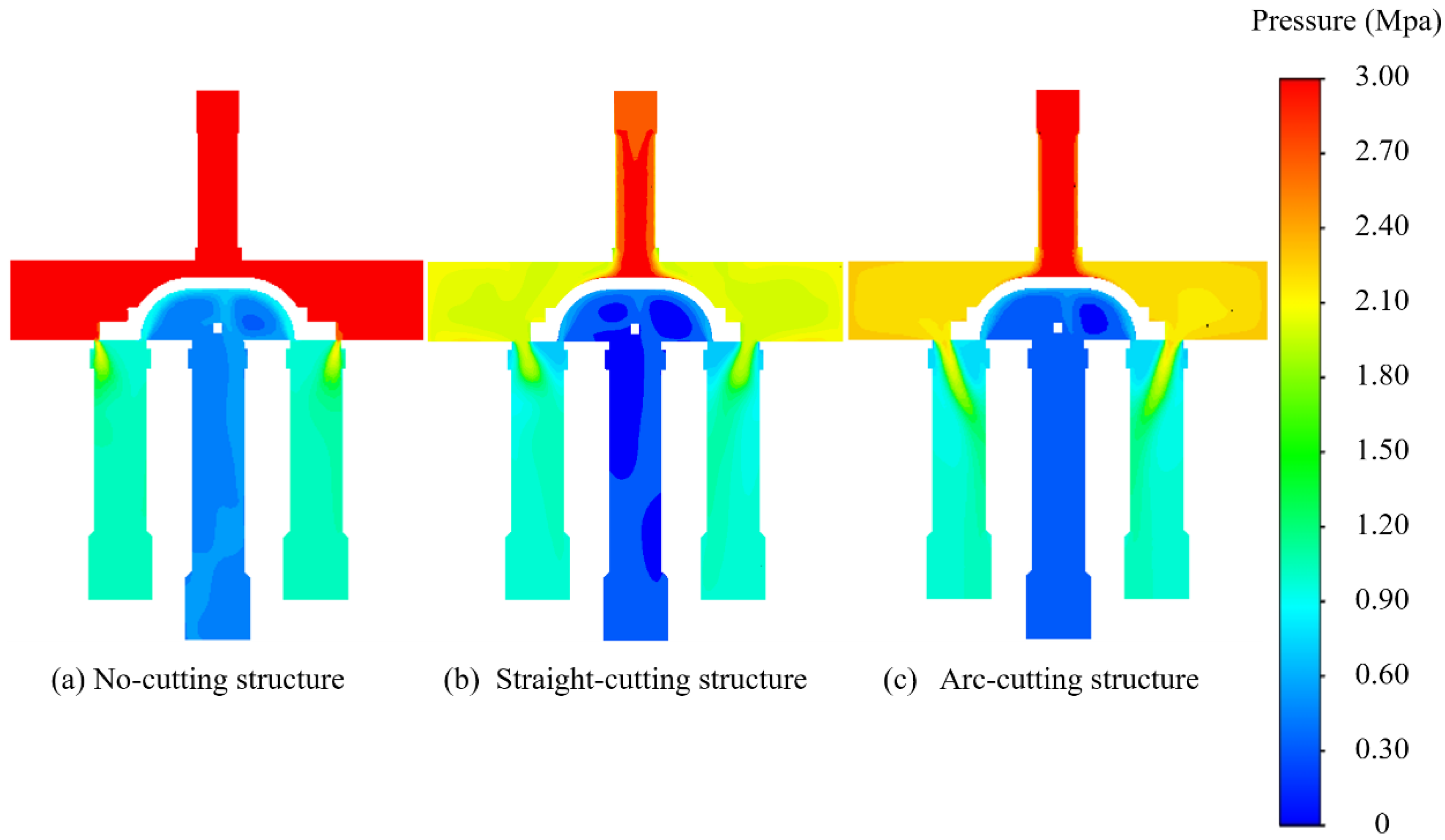
Figure 8 and
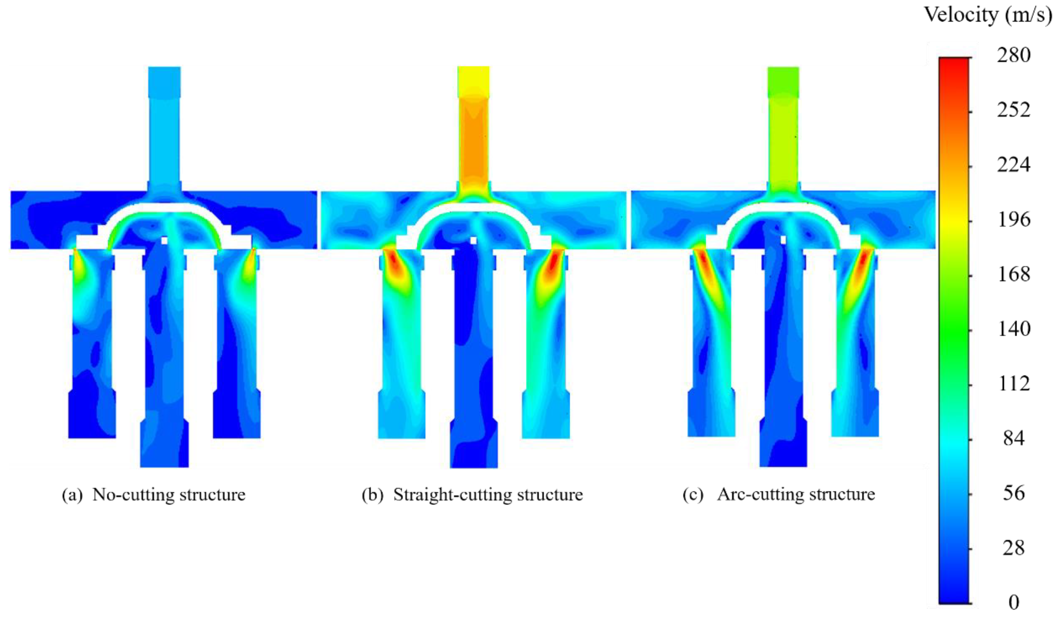
Figure 9 show the distribution of flow field pressure and velocity in the chamber when the slider is in the middle position.
It can be seen from
Figure 8, when the slider is in the middle position, the pressure in the chamber of the slider no-cutting structure is the largest, and the pressure at each position in the chamber is almost equal to that of D tube, at about 3Mpa. The pressure in the chamber of the slider with straight-cutting and arc-cutting structures is relatively small, at about 2.2Mpa, which is obviously lower than that of the four-way reversing valve no-cutting structure. The pressure distribution in the whole chamber is relatively uniform. In addition, it can be seen from the pressure field that on both sides of the slider, the high pressure release area of the straight-cutting structure and the arc-cutting structure is obviously larger than that of the no-cutting structure, which is also the main reason why the pressure distribution in the chamber of the cutting structure is lower than that of the no-cutting structure.
It can also be seen from the distribution of flow field velocity in
Figure 9 that the fluid velocity in the chamber of the slider with cutting-structure is higher than that of the no-cutting structure. The slider with cutting-structure on both sides of the slider has an obvious velocity gradient, corresponding to the pressure cloud diagram. No-cutting structure, the pressure in the chamber is lower on the whole, and there is a certain flow dead zone, which is not conducive to fluid flow.
5.2. Experimental comparison and analysis
In order to verify the authenticity of the simulation, a pressure test bench for the valve chamber of the four-way reversing valve was designed and built. In order to facilitate the arrangement of sensors, a pressure sensor was placed on the chamber wall above the E tube in the valve chamber of the four-way reversing valves to measure the change of pressure at this point during the reversing process of the four-way reversing valve. The experimental platform is horizontal, as shown in
Figure 10.
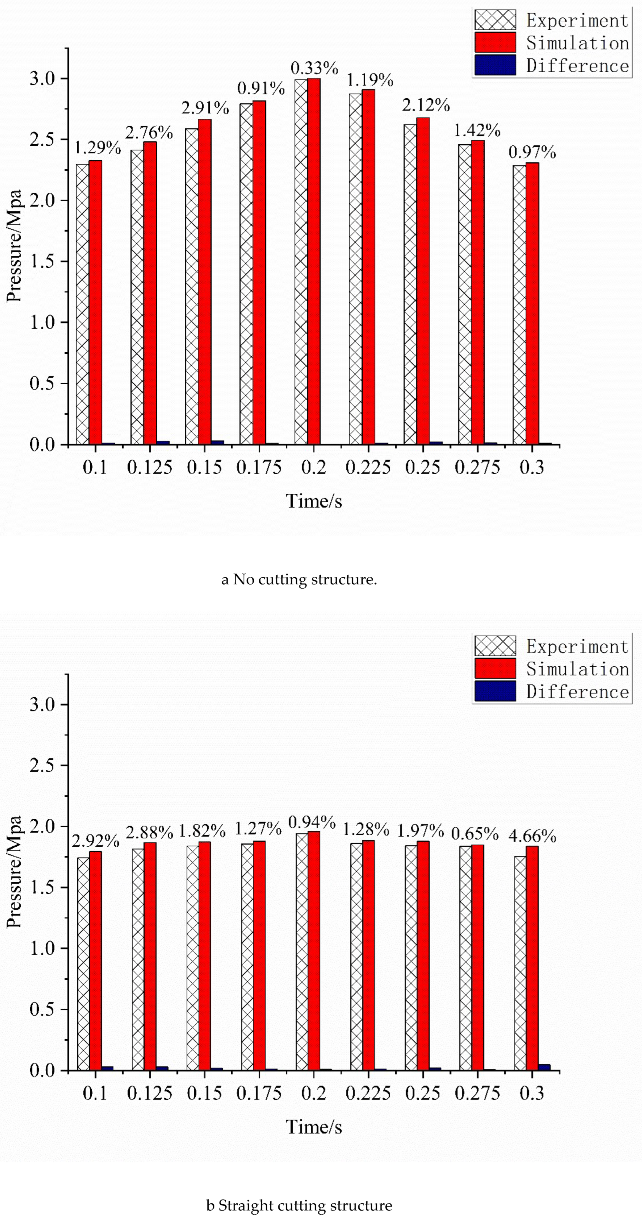
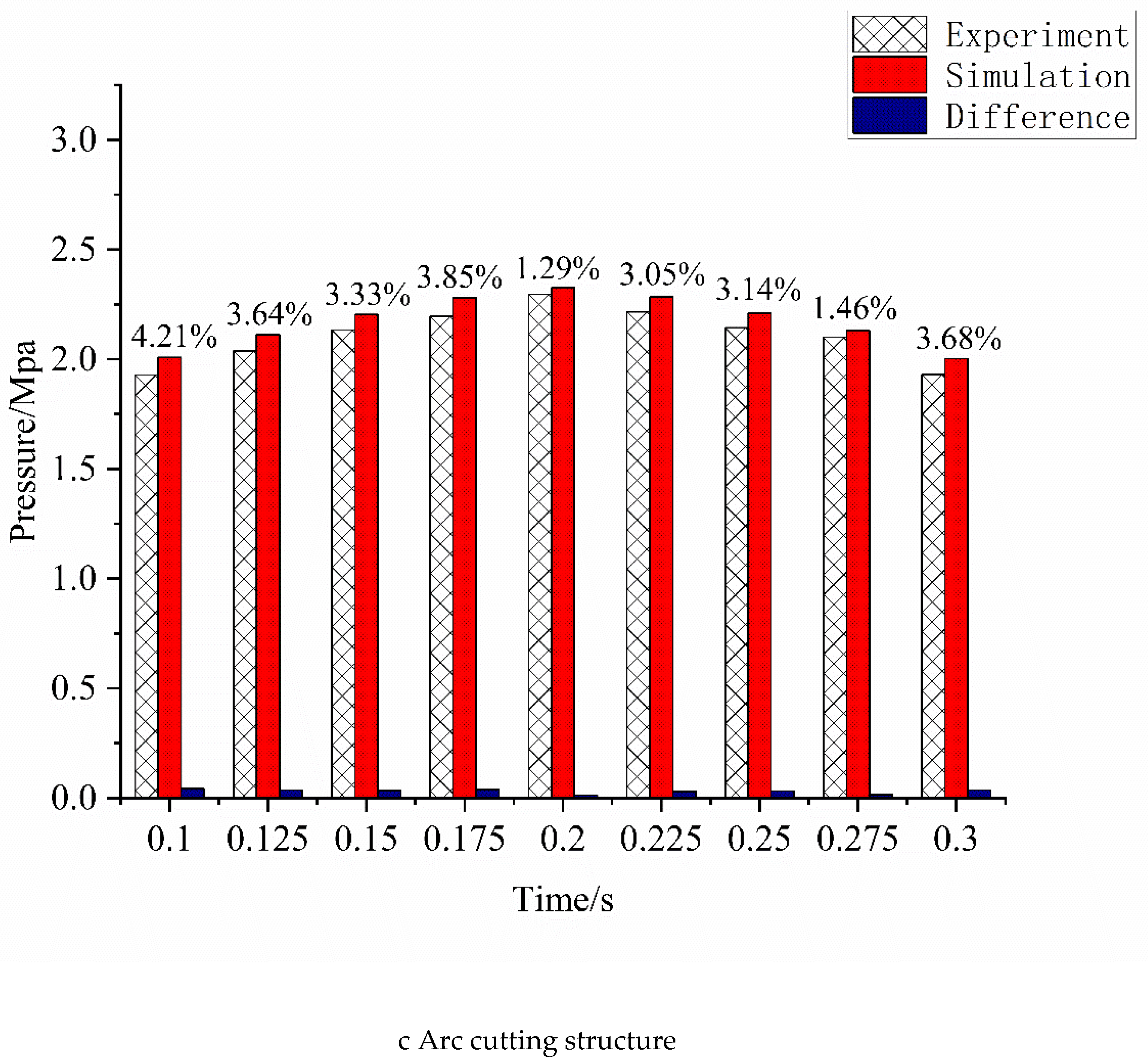
After the reversing stability of the four-way reversing valves, the experiment was carried out to eliminate the unstable factors at the beginning and near the end of the reversing. The count was from 0.1s of each reversing to 0.3s before the end. The pressure value was taken every 0.05s, the pressure was measured 5 times and the average value was taken. The pressure results of this position point were extracted from the pressure field simulation results of three slider structures respectively and compared with the average test results of three different slider structures. The results are shown in
Figure 11.
As can be seen from the figure, the pressure variation trend calculated by numerical simulation tends to be consistent with the test results. The maximum error is 4.66% when the slider moves 0.3s in the straight-cutting structure, and the allowable error range of engineering is ±5%. Therefore, the results obtained by numerical simulation are reliable and meet the accuracy requirements.
5.3. Investigation of effects of slider structure on the reversing performance
The basic condition of the four-way reversing valves is that the thrust
Ft of the slider is greater than the friction between the slider and the valve seat
f,
f=μFr.
Fr is the positive pressure of the slider,
μ is the kinetic friction factor, only related to the material and roughness of the contact surface,
Fr is defined here as the resistance of the slider. Therefore, the reversing performance of the reversing valves depends on the thrust
Ft and resistance
Fr of the slide [
11].
Where
Pl and
Pr are the pressure on the left and right ends of the slider, Mpa;
Sc is the axial cross-sectional area of the slider,m
2.
Where Pt and Pb are the pressure on the upper and lower surfaces of the slider, Mpa; St and Sb are the areas of the upper and lower surfaces of the slider, m2.
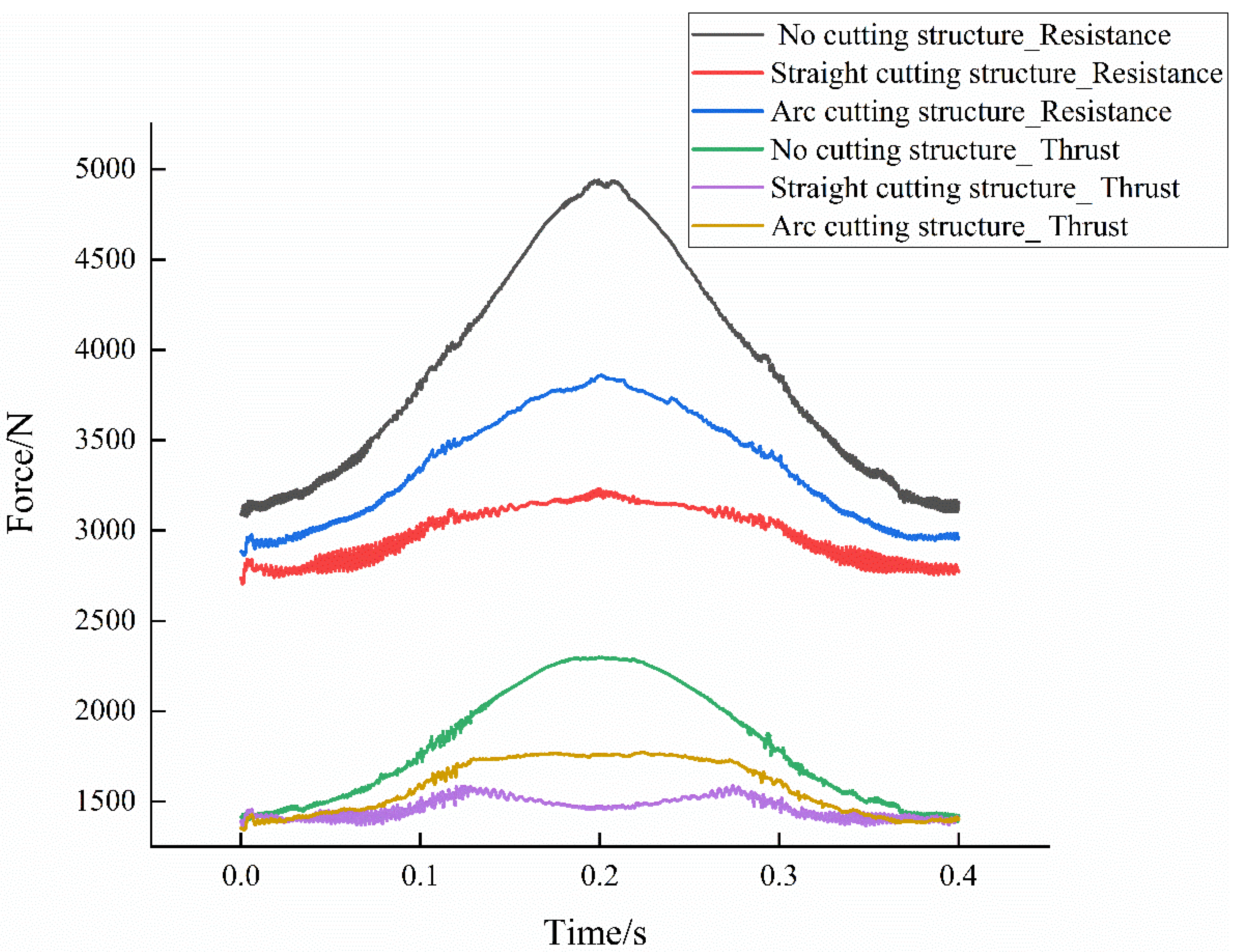
The resistance and thrust changes of three slider structures in the process of reversing are shown in
Figure 12. It is obvious from the figure that thrust of the three sliders is almost equal at the beginning and end of reversing. With the passage of reversing time, thrust of the no-cutting sliders first increases and then decreases at the middle position until the end of reversing. The thrust of the straight-cutting slider first increases, reaches the maximum at 0.12s and then decreases, then increases again at the middle position, and then decreases at 0.28s until the end of reversing. The thrust of the circular arc cutting slider increases at the beginning, becomes stable at 0.12s, and decreases at 0.28s until the end of the reversing.
It can also be seen from
Figure 6 and
Figure 8 that, at the beginning, the pressure in the chamber of the three slider structures is similar. When the slider reaches the middle position, the pressure in the chamber of the no-cutting structure is the largest, while the pressure in the chamber of the straight-cutting and arc-cutting structure is small. It can also be seen from
Figure 12 that the resistance of no-cutting structure is the largest, followed by arc-cutting structure and straight -cutting structure. In addition, the change trend of resistance in the course of reversing is from first increasing to the middle position decreasing until the end of reversing. This is because with the movement of the slider, the slider surface is directly affected by the impact area of high pressure fluid more and more large, reached the middle position when the maximum, and then gradually reduced until the end of the reversing, and the effective compression area of the no-cutting structure is the largest, so the resistance of the no-cutting structure slider is the largest.
Since the resistance and thrust trends of the three structural sliders in
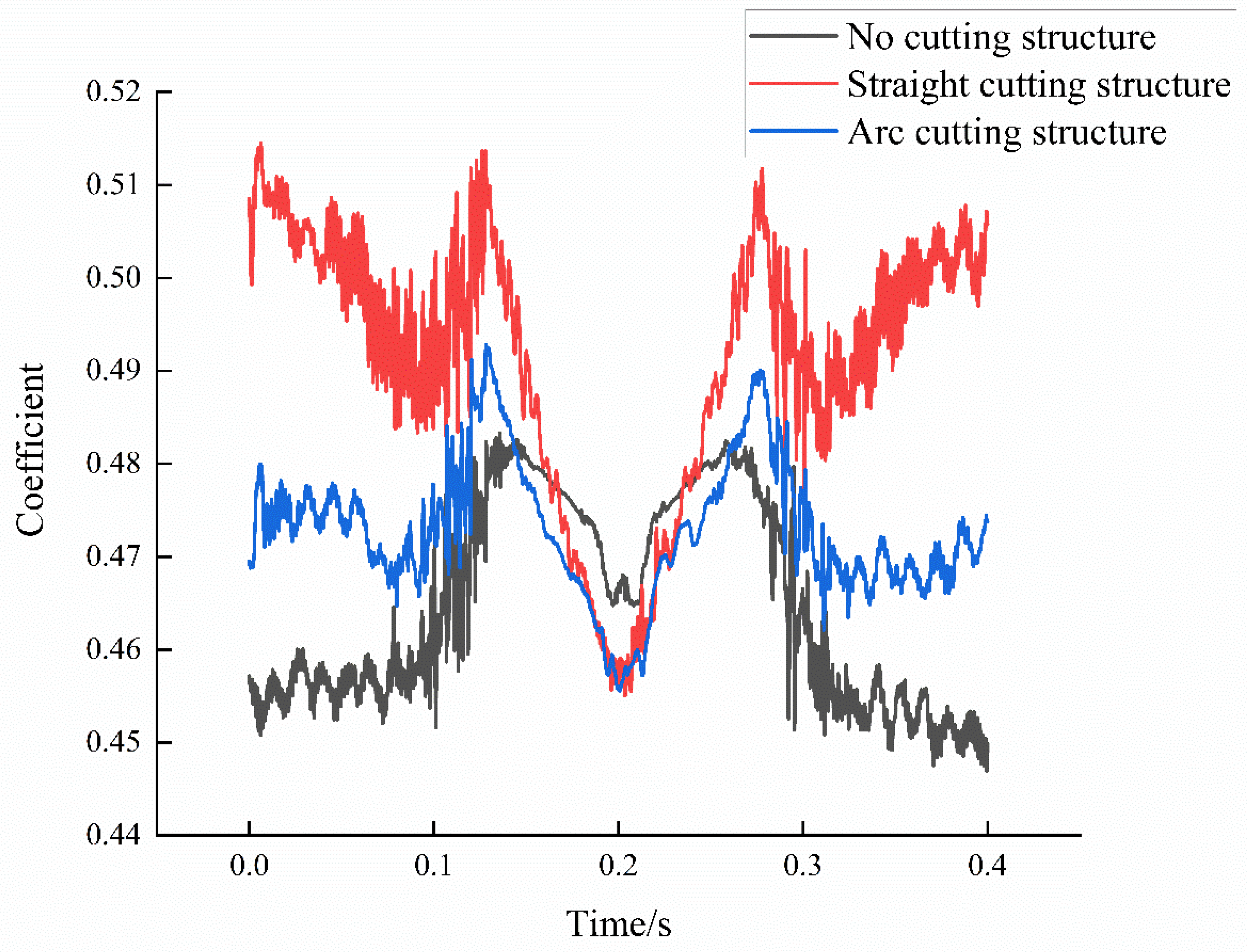
Figure 12 are consistent, the reversing performance cannot be directly judged. In order to further compare the reversing performance of the three structures, the reversing process of the four-way reversing valve is observed by using the ratio of slider resistance and thrust (resistance to thrust ratio). The smaller the resistance-to-thrust ratio, the more conducive to reversing. The resistance-to-thrust of the three slider structures is shown in
Figure 13.
It is obvious from the figure that the resistance-to-thrust ratio of the slider of the no-cutting structure is the smallest at the beginning and end of the reversing stage, followed by the arc-cutting structure, and the resistance-to-thrust ratio of the straight-cutting structure is the largest. However, at the middle position, the resistance-to-thrust ratio of the no-cutting structure is the largest, and the resistance-to-thrust ratio of the arc-cutting structure and the straight-cutting structure is the same, and both are smaller than the no-cutting structure. As the middle position is the most important position in the whole reversing process, the positive pressure at this time is the largest and the reversing is the most difficult. Therefore, the reversing performance of the cutting structure slider is better than the no-cutting structure slider. In addition, it can be seen from the figure that the resistance to thrust ratio transformation of the slider of the straight-cutting structure fluctuates more violently than the arc-cutting structure, which is easy to generate vibration and noise in the reversing process, also unfavorable to the reversing process. Therefore, the reversing performance of the arc-cutting slider is optimal.
6. Conclusions
- (1)
The slider structure affects the pressure and velocity distribution in the valve chamber during the reversing process of the four-way reversing valve. At the beginning of reversing, there is little difference in the pressure and velocity distribution in the valve chamber of no cutting slider, straight cutting and arc cutting slider. When the slider slides to the middle position of the four-way reversing valve, the pressure in the chamber of the no-cutting structure slider is greater than that in the chamber of the cutting structure slider.
- (2)
At the beginning and end of the reversal, the thrust of the three structures is almost the same. In the reversing process, the thrust received by the no-cutting structure slider is first large and then small, and reaches the maximum in the middle position. The thrust of the straight-cutting structure slider first increases and then decreases, and then increases and then decreases. The thrust of the circular cutting structure slider first increases and then stabilizes for a period of time and then decreases. The resistance of the three structures increases first and then decreases, among which the resistance of the slider without cutting the structure is the largest.
- (3)
In the middle of the reversing position, the resistance-to-thrust ratio of the no-cutting structure slider is the largest. The resistance-to-thrust ratio of the straight-cutting structure slider is similar to the arc-cutting structure slider, but the resistance-to-thrust ratio of the arc-cutting structure slider changes gently, which is more conducive to reversing.
CRediT authorship contribution statement
Kepeng Zhang: Methodology, Writing-original draft, Simulation, Experiment, Investigation. Dazhuan Wu:Supervision, Methodology, Investigation, Funding acquisition. Huan Wang: Simulation, Methodology.
Declaration of competing interest
The authors declare that they have no known competing financial interests or personal relationships that could have appeared to influence the work reported in this paper.
References
- G. Kim, J. Lee, J. Park, S. Song, Flow visualization and noise measurement of R410A two-phase flow near electric expansion valve for heating cycle of multi-split air-source heat pump, Appl. Therm. Eng. 157 (2019) 113712. [CrossRef]
- T. Lai, S. Yan, Y. Wang, X. Liu, S. Yang, P. Ding, Y. Hou, Experimental study on vaporous cavitation of R134a in micron clearance, Exp. Therm. Fluid Sci. 129 (2021) 110484. [CrossRef]
- G. Li, X. Ding, Y. Wu, S. Wang, D. Li, W. Yu, X. Wang, Y. Zhu, Y. Guo, Liquid-vapor two-phase flow in centrifugal pump: Cavitation, mass transfer, and impeller structure optimization, Vacuum. 201 (2022) 111102. [CrossRef]
- M. Han, Y. Liu, D. Wu, X. Zhao, H. Tan, A numerical investigation in characteristics of flow force under cavitation state inside the water hydraulic poppet valves, Int. J. Heat Mass Transf. 111 (2017) 1–16. [CrossRef]
- S.-H. Park, T.-H. Phan, W.-G. Park, Numerical investigation of laser-induced cavitation bubble dynamics near a rigid surface based on three-dimensional fully compressible model, Int. J. Heat Mass Transf. 191 (2022) 122853. [CrossRef]
- Y. Zhang, J. Xu, L. Cheng, Y. Zhao, S. Peng, S. Jiang, Exploring cavitation erosion resistance of ZrN nanocrystalline coating prepared by double-cathode glow discharge plasma technique, Vacuum. 182 (2020) 109697. [CrossRef]
- J.R. Valdés, J.M. Rodríguez, R. Monge, J.C. Peña, T. Pütz, Numerical simulation and experimental validation of the cavitating flow through a ball check valve, Energy Convers. Manag. 78 (2014) 776–786. [CrossRef]
- Y. Song, R. Hou, Z. Liu, J. Liu, W. Zhang, Ultrasonics Sonochemistry Cavitation characteristics analysis of a novel rotor-radial groove hydrodynamic cavitation reactor, Ultrason. Sonochem. 86 (2022) 106028. [CrossRef]
- J. Liang, X. Luo, Y. Liu, X. Li, T. Shi, A numerical investigation in effects of inlet pressure fluctuations on the flow and cavitation characteristics inside water hydraulic poppet valves, Int. J. Heat Mass Transf. 103 (2016) 684–700. [CrossRef]
- W.B. Jeong, H.S. Han, J.Y. Mo, J.K. Lee, Experimental study of the effects of the cycle characteristics on the refrigerant-induced noise in system air-conditioner, J. Mech. Sci. Technol. 21 (2007) 1112–1119. [CrossRef]
- Y. Zhang, X. Liu, B. Li, S. Sun, J. Peng, W. Liu, J. He, L. Wei, Hydrodynamic characteristics and optimization design of a bio-inspired anti-erosion structure for a regulating valve core, Flow Meas. Instrum. 85 (2022) 102173. [CrossRef]
- W. Xu, Q. Wang, D. Wu, Q. Li, Simulation and design improvement of a low noise control valve in autonomous underwater vehicles, Appl. Acoust. 146 (2019) 23–30. [CrossRef]
- Y. Hou, C. Liu, J. Ma, J. Cao, S. Chen, Mass flowrate characteristics of supercritical CO2 flowing through an electronic expansion valve, Int. J. Refrig. 47 (2014) 134–140. [CrossRef]
- G.F. Ou, J. Xu, W.Z. Li, B. Chen, Investigation on Cavitation Flow in Pressure Relief Valve with High Pressure Differentials for Coal Liquefaction, Procedia Eng. 130 (2015) 125–134. [CrossRef]
- D. Habibnejad, P. Akbarzadeh, A. Salavatipour, V. Gheshmipour, Cavitation reduction in the globe valve using oblique perforated cages: A numerical investigation, Flow Meas. Instrum. 83 (2022) 102110. [CrossRef]
- C. Wang, G.X. Li, Z.Y. Sun, L. Wang, S.P. Sun, J.J. Gu, X.J. Wu, Effects of structure parameters on flow and cavitation characteristics within control valve of fuel injector for modern diesel engine, Energy Convers. Manag. 124 (2016) 104–115. [CrossRef]
- H.M. Ariyadi, J. Jeong, K. Saito, Computational analysis of hydrogen flow and aerodynamic noise emission in a solenoid valve during fast-charging to fuel cell automobiles, J. Energy Storage. 45 (2022) 103661. [CrossRef]
- H. Wang, Z. Zhu, H. Xu, J. Li, Effects of throttling structures on cavitation flow and circumferential uniformity in a control valve, Eng. Fail. Anal. 134 (2022) 106025. [CrossRef]
- S. Corbera, J.L. Olazagoitia, J.A. Lozano, Multi-objective global optimization of a butterfly valve using genetic algorithms, ISA Trans. 63 (2016) 401–412. [CrossRef]
- F.T. Knabben, C. Melo, C.J.L. Hermes, A study of flow characteristics of electronic expansion valves for household refrigeration applications, Int. J. Refrig. 113 (2020) 1–9. [CrossRef]
|
Disclaimer/Publisher’s Note: The statements, opinions and data contained in all publications are solely those of the individual author(s) and contributor(s) and not of MDPI and/or the editor(s). MDPI and/or the editor(s) disclaim responsibility for any injury to people or property resulting from any ideas, methods, instructions or products referred to in the content. |
© 2023 by the authors. Licensee MDPI, Basel, Switzerland. This article is an open access article distributed under the terms and conditions of the Creative Commons Attribution (CC BY) license (http://creativecommons.org/licenses/by/4.0/).
