1. Introduction
Duplex stainless steel was a type of stainless steel with about half ferrite and half austenite. It was characterized by high toughness, good resistance to pitting, crevice corrosion, stress corrosion and corrosion fatigue. Developments in marine engineering, aeronautics, space, transportation, and other industries greatly promoted the continuous development of welding technology. Enhancement of welding productivity to achieve welding automation and improve welding quality had become a crucial issue in the development of welding technology [
1,
2,
3,
4,
5]. Twin-wire GMAW welding technology could achieve high speed welding and good deposition rate and so, had received much popularity as well as research attention at home and abroad [
6,
7,
8,
9,
10]. The welding effect of twin-wire double-pulsed GMAW welding was affected by several parameters such as voltage, current, welding wire, base metal, and welding speed; especially the welding speed that directly determined the welding production efficiency. Under the conventional conditions of twin-wire double-pulsed GMAW welding process, although the welding parameters had important effects on the weld quality, it was very difficult to increase the welding speed and improve the weld quality simultaneously while only relying on the adjustment and optimization of welding parameters. As the welding speed increased to a certain value, the weld seam exhibited defects such as non-penetration, humping, and undercut [
11,
12,
13,
14]. These defects not only lessened the inferior appearance of the weld seam, but also seriously affected the mechanical properties of the welded seam, which was the main reason behind the limitations on the welding speed and efficiency.
The research on the mechanism of twin wire welding mainly focused on the interaction mechanism of twin arc and arc stability, metal transfer mechanism and stability of twin wire welding [
15,
16]. Moinuddin et al. [
17] found that the reversal phase of the leading and trailing arcs could be used to control the stability of the welding process. As the current of the leading arc was greater than that of the trailing arc, the arc stability was better. Wu et al. [
18] found that the twin-arc interference of the reversal phase was more serious by investigating the high-current twin-wire pulsed GMAW welding, while the interference behavior significantly reduced when the phases were identical. Ye et al. [
19] found that when the trailing arc increased, the leading arc was significantly closer to the trailing arc due to the electromagnetic effect and the droplet transition mode of the leading arc transited from droplet transition to rotation transition. With respect to the welding speed, Ueyama et al. [
20] found that to ensure good weld seam quality, the maximum welding speed should vary between 2-3 m/min, which was about 60-150% higher than that of single wire pulse welding. Especially when using the push-angle layout, the welding speed could be increased to 3 m/min. As for the formation and microstructure of the welded seam, Wu et al. [
21] found that the difference between the leading and trailing arcs impacted the microstructure, hardness, heat-affected zone, and depth-width ratio of the welded seam. Chen et al. [
22] found that the horizontal component of the arc pressure drived fluid to the center of the two arcs, which resulted in the local bulging phenomenon. With the increase in phase difference, the bulged height and seam width gradually decreased when the penetration depth and residual height of the seam increased, thus worsening the appearance. Ueyama et al. [
23] analyzed the influencing factors for seam formation during high-speed welding and found that the current, inclination, and twin-wire spacing had significant effects. Starting from the basic requirements to avoid humping and undercut, the optimum process parameters for high-speed welding were obtained at a welding speed of 4.5 m/min. Ueyama et al. [
24] studied the effects of twin-wire spacing and gas mixing ratio on the arc interruption and abnormal arc voltage during twin-wire GMAW welding, and reasonable ranges of wire spacing and gas mixing ratio were provided. By controlling the arc length and pulse timing of the twin-wire GMAW welding. Ueyama [
25] successfully minimized the arc interference and avoided arc interruption. They established a stable welding process control by arc length and confirmed that the stability control was not affected by the fluctuation in extension in wire length and feed speed. In context of the welding of steel plate in the ship-building industry, Sterjovski et al. [
26] proposed a method to reduce the generation of cracks and studied the formation mechanism of solidified cracks in twin-wire GMAW welding.
On the basis of conventional twin-wire GMAW welding process, the paper innovatively introduced additional shielding gas. Through the air-shielding characteristics and mechanical properties of the gas [
27], the effects of twin-wire GMAW welding on the formation mechanical properties and microstructure of the welded seam were studied under the additional shielding gas with different flowrates.
2. Materials and Methods
2.1. Experimental Equipment and Methods
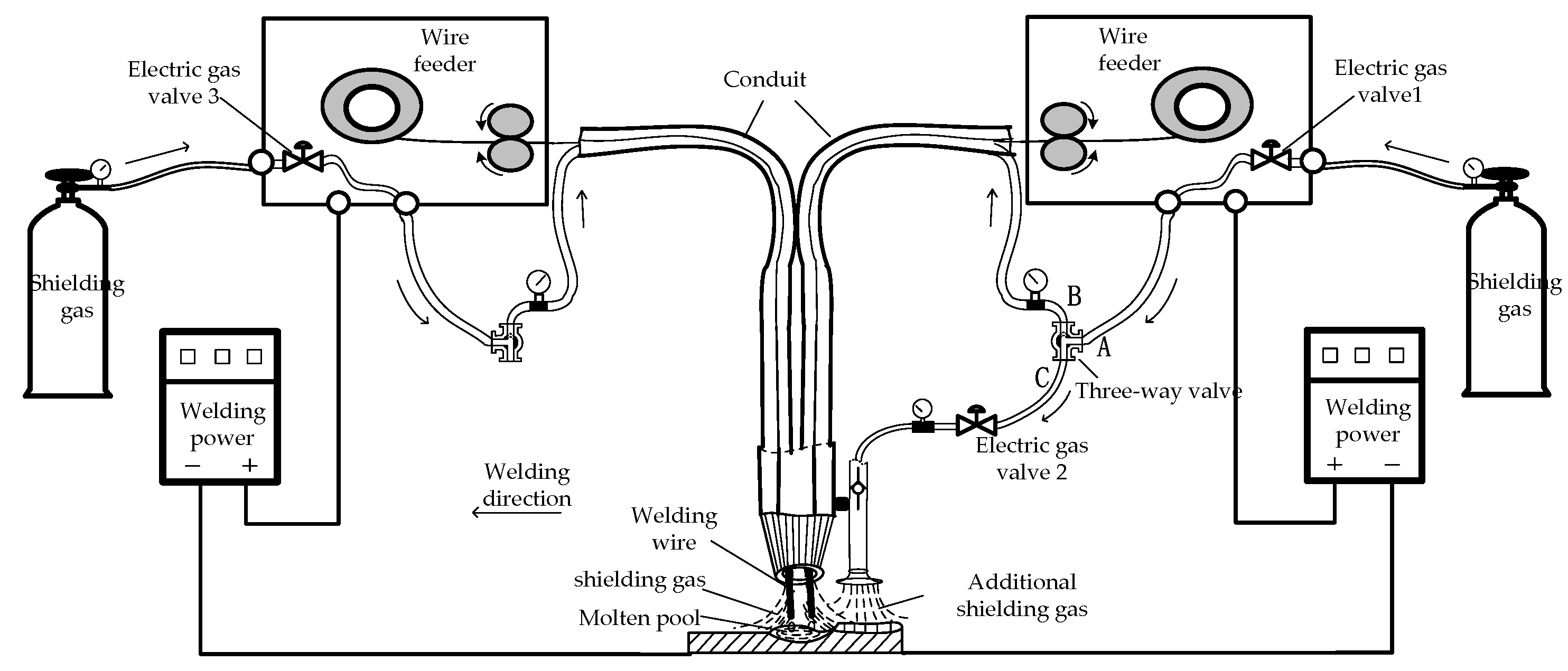
The schematic diagram of twin-wire pulsed GMAW welding under the action of additional shielding gas was shown in
Figure 1. The welding test platform included lead screws, wire feeding mechanisms, protection devices, automatic walking control mechanisms, data acquisition cards, and arc dynamic wavelet analyzers which used to collect real-time signals such as current and voltage, energy input, and dynamic resistance. The additional shielding gas device can better meet the protection requirements of high-speed welding melt pool by adding three-way gas adjustable valves and adjusting the gas flow meters of branch B and C appropriately. At the same time, an additional electric gas valve 2 and a one-way valve were also installed, which can facilitate valve control. The shielding gas nozzle head also had a protective effect. These can be efficiently combined with existing welding equipment to better meet the requirements of gas flow regulation. The principle of this system was relatively simple. During operation, the gas source at the cylinder entered the electric air valve 1 of the gas supply branch, and then the valve was controlled by a button. During the working process, when welding begins, the gas valve was opened, and shielding gas can enter the corresponding conduit. The conduit and regulating valve A end remained connected. The main function of the three-way gas adjustable valve was to regulate the gas from the main circuit and distribute it appropriately. In order to meet the requirements of B and C outlet gas flow and provide appropriate protection, the airflow of branch C was output from C, and then controlled to be on or off through gas valve 2. During this process, the airflow sprayed from the nozzle covers the newly welded seam, which can provide efficient shielding gas for the weld seam in this area and improve welding quality.
2.2. Experimental Materials and Processing
The base material used in the test was 2205 duplex stainless steel plate with dimension of 250×100×3 mm. The ER2209 wire with a diameter of 1.2 mm was used and the relevant components are shown in
Table 1. The test conditions are: duplex ER2209 stainless steel welding wire with diameter of 1.2 mm undergoes butt welding on the duplex stainless steel plate. The welding process was protected by high-pure argon gas with set flowrate of 8, 12, 16 L/min for maintaining stable wire feeding. In order to verify the effects of additional shielding gas with different flowrates on the welding process of duplex stainless steel, nine sets of tests were planned during the study. The main parameters such as the flowrate of additional shielding gas, welding current, and welding speed are shown in
Table 2.
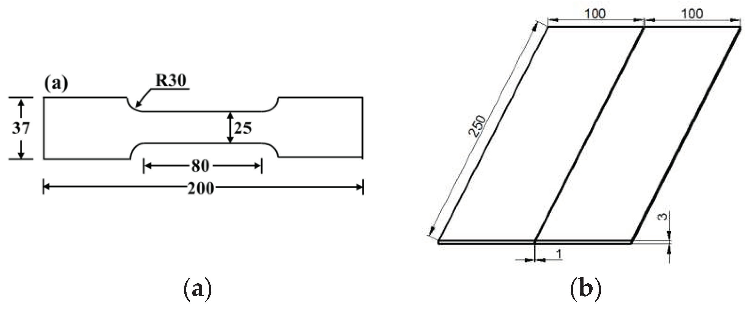
Butt welding with a gap of 1 mm was adopted and shown in
Figure 2a. Before the welding test, the sample was first polished to remove the oxides. The surfaces were cleaned with ethanol and the welding starts after the surfaces were dried. After welding, a spark discharge wire cutter was used to remove 20 mm from both ends of the welded seam and the specimens for tensile test and metallographic observation were taken along the direction vertical to the seam. The dimensions of the specimens are shown in
Figure 2b.
The microstructure characteristics of welded joints were analyzed using optical microscopy Olympus (OM, Japan) and scanning electron microscopy (SEM, Japan). Vickers micro-hardness test was conducted on the polished and etched specimens with a testing time of 15 seconds per test point, a load of 200 g, and a step size of 1 mm. Room temperature tensile test was carried out on an INSTRON tester(INSTRON, USA). After the tensile test, the fracture morphology of the welded joint was observed by SEM.
3. Results
3.1. Formation of the Weld Seam
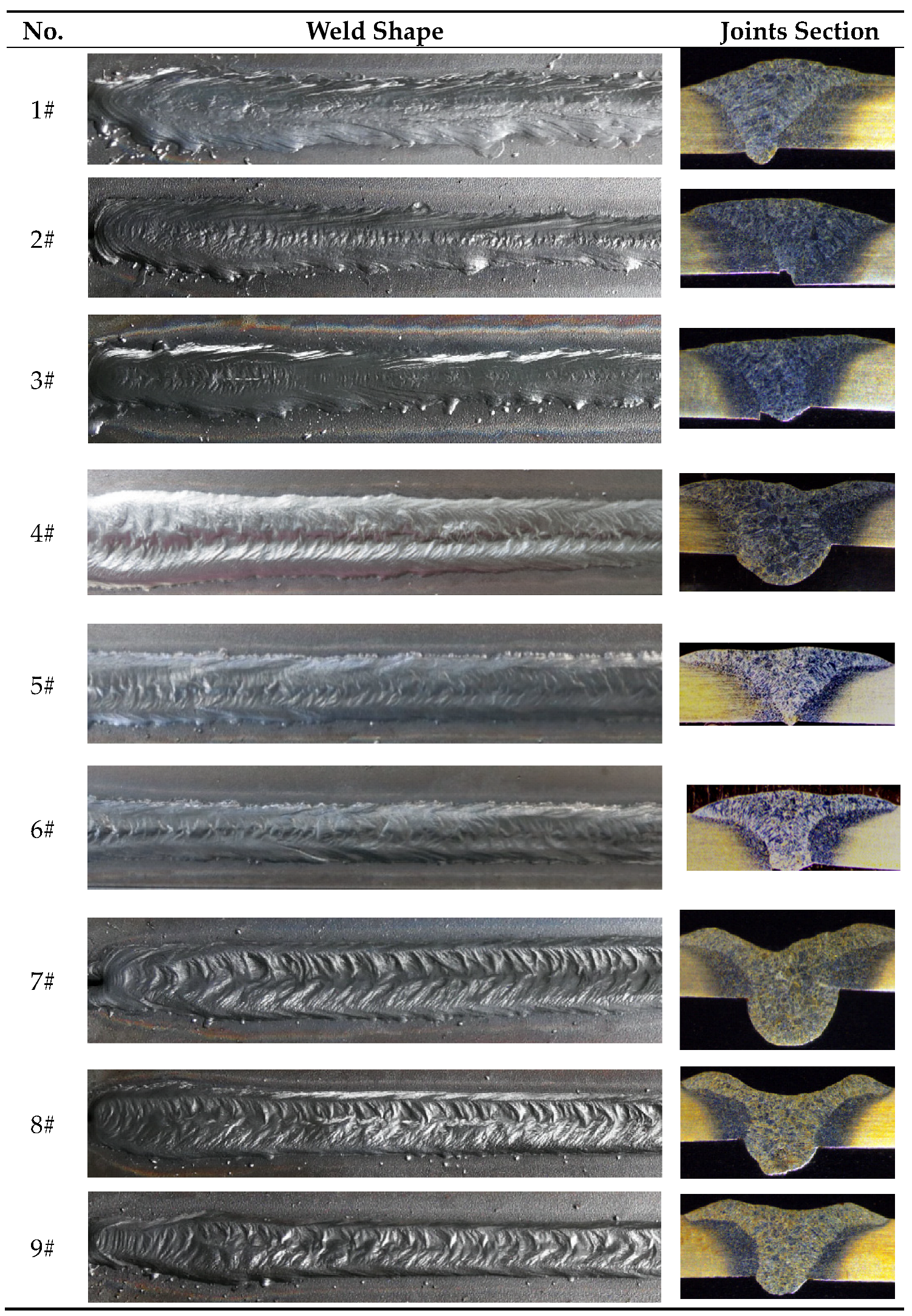
It can be seen from
Table 3 that the seam exhibits an overall uniform and flat morphology, which clearly manifests the improvement of additional shielding gas on the shaping process of welded seam. It can be seen from
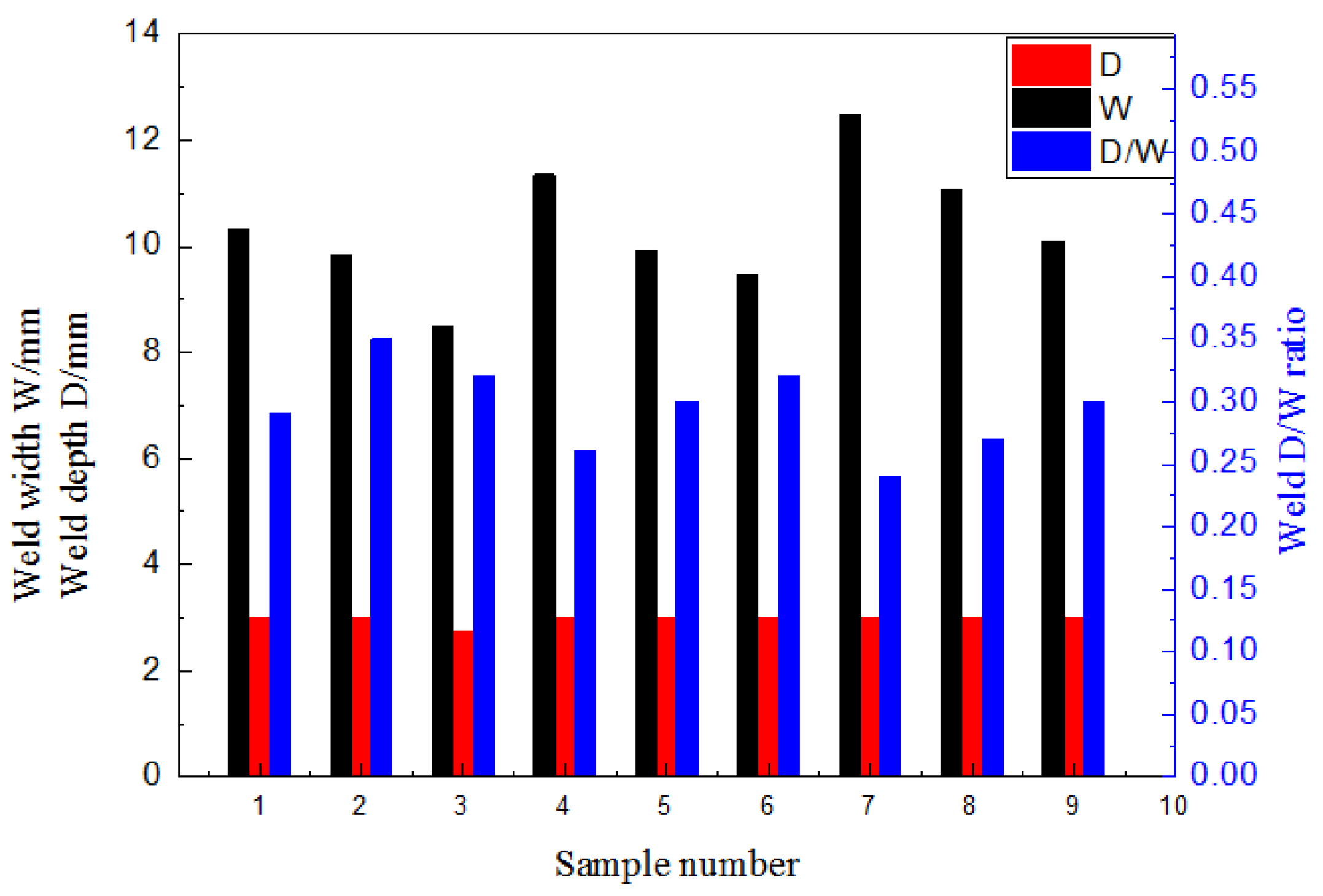
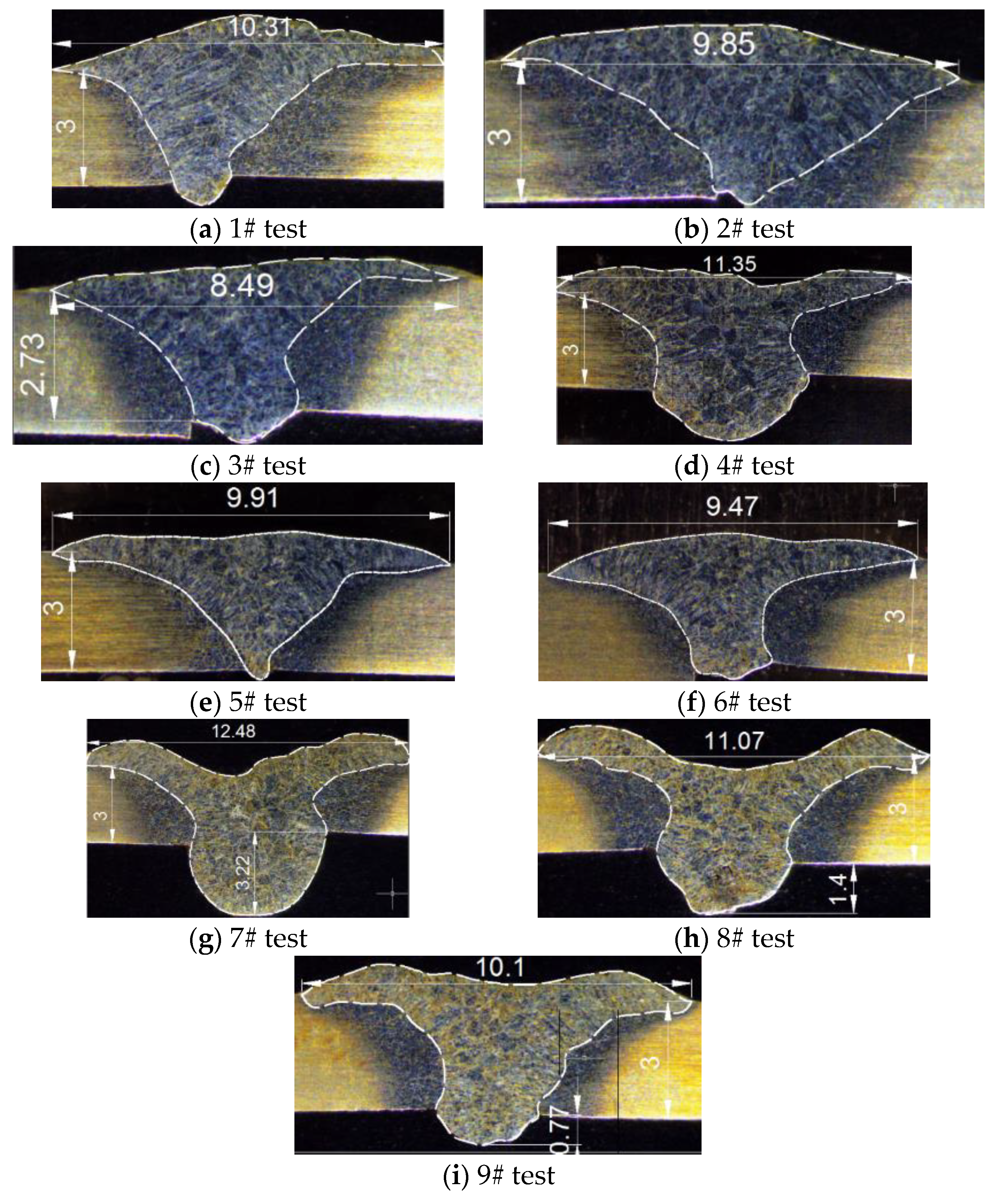
Figure 3 that under an identical welding speed and current, the higher flowrate of the additional shielding gas produces a wider welding seam, deeper penetration depth, and smaller aspect ratio (depth/width). The appearance of the seam formed under the additional shielding gas changes and the specific dimensions of the seam were shown in
Figure 4. As the flowrate of the gas increased, the width of the seam increased gradually and the residual height gradually decreased since the different flowrates of additional shielding gas brought the variation in the impact force acting on the welded seams. As the flowrate of the additional shielding gas was 12 L/min, the impact force of the jet was more suitable for the set of welding parameters that best improved the welded seam; the impact force generated by the gas under a flowrate of 8 L/min was slightly smaller and the improvement on the seam was not as good as that under the gas flowrate of 12 L/min. As the gas flowrate was 16 L/min, the over-protection phenomenon of the gas jet occurred on the welded seam. Under an excessively large flowrate of additional shielding gas, the seam had a grooved morphology with a lower middle part and higher sides, which indicated that the impact force of the jet exceeds the actual requirement of the liquid pool significantly [
28]. The reason for the formation was that the molten pool becomes depressed under the excessive impact force acting on the molten pool. The liquid-solid phase transition was completed before the metal bulging on both sides recover to the middle region so the metal exhibits a grooved shape after the solidification was completed. At the same time, a small amount of drop-shaped metal particles dispersed on both sides of the seams in 7#, 8# and 9# tests. Due to the excessive gas jet, a portion of the liquid metal separated from the molten pool and was splashed to the surface of the base material under a strong impact force and then forms metal particles [
29].
3.2. Results of Metallographic Tests
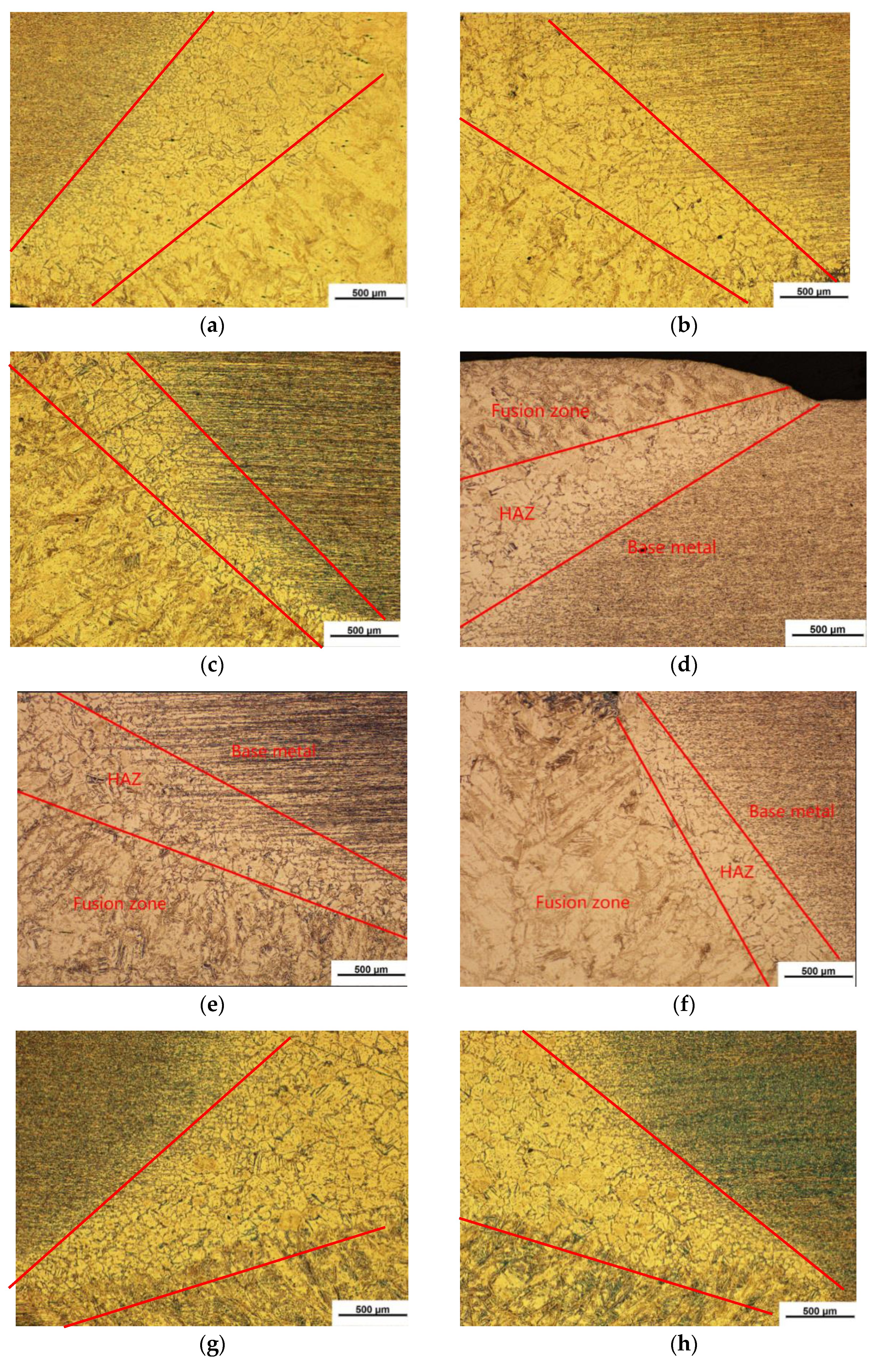
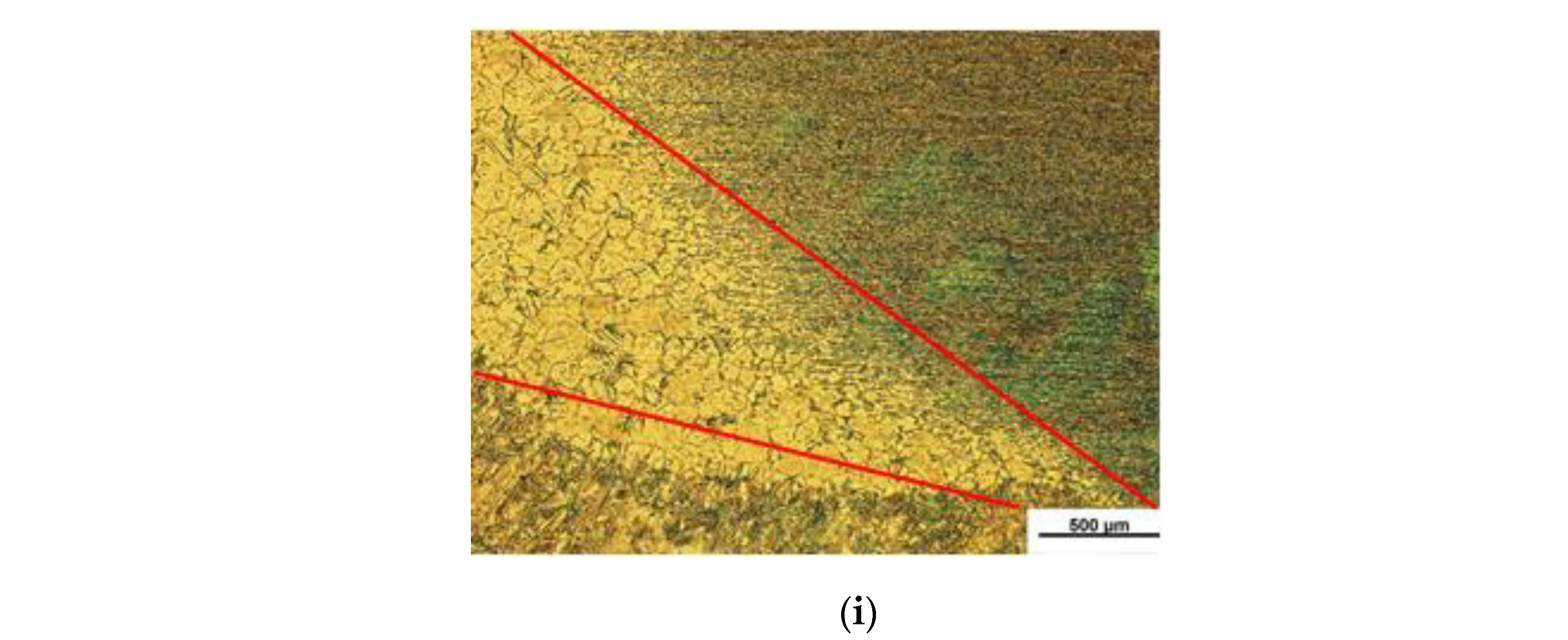
The fusion zone (FZ), heat-affected zone (HAZ), and base metal (BM) of the welded seams of the nine samples were analyzed and the microstructure of the HAZ was observed at 50x magnification, as shown in
Figure 5. The HAZ widths between the weld seam and the 2205 base metal in tests 1#,2#, and 3# were 500~1600 μm, 400 μm~1000 μm, and 300 μm~500 μm, respectively. The HAZ widths in 4#, 5#, and 6# tests were 150 μm~1000 μm, 300 μm~800 μm, and 150 μm~400 μm, narrower than those in 1#, 2# and 3# tests, respectively. The HAZ widths in 7#, 8# and 9# tests are 400 μm~1500 μm, 300 μm~1200 μm, and 200 μm~1000 μm, respectively wider than those in 4#, 5# and 6# tests. It can be seen that when the flowrate of additional shielding gas was 12 L/min (4#, 5# and 6#), the HAZ range is the smallest, followed by the HAZ range corresponding to the additional shielding gas flowrate of 8 L/min (1#, 2# and 3#). The HAZ range under the additional shielding gas with a flowrate of 16 L/min (7#, 8# and 9#) is the largest. After introducing additional shielding gas with different flowrates, the flowability of the molten metal in the pool under a larger gas flowrate (12 L/min) is better than that under 8 L/min, indicating greater driving force of the metal diffusion and a shorter liquid residence time, so that the HAZ is smaller than that under the smaller flowrate of the additional shielding gas. However, if the flowrate of the additional shielding gas is too large (16 L/min), the molten pool can depress under the impact force and the downward flow of metal is obvious so the metal completes its liquid-solid transition before the metal that bulges on both sides recovers to the middle region. The metal takes on a grooved shape after being completely solidified, which obviously exceeds the actual needs of the molten pool. Since the metal bulge that flows downward is significant, it is difficult for this portion of the metal to undergo heat transfer. The resultant slower heat dissipation causes the HAZ range under the excessive flowrate of the additional shielding gas to be larger than that under the smaller flowrate of the additional shielding gas. In general, regardless of the flowrate of the additional protective gas, the HAZ formed under higher welding speed is smaller than that under lower welding speed, for instance, the HAZ ranges in tests 3#, 6#, and 9# are smaller than those in tests 2#, 5#, and 8#.
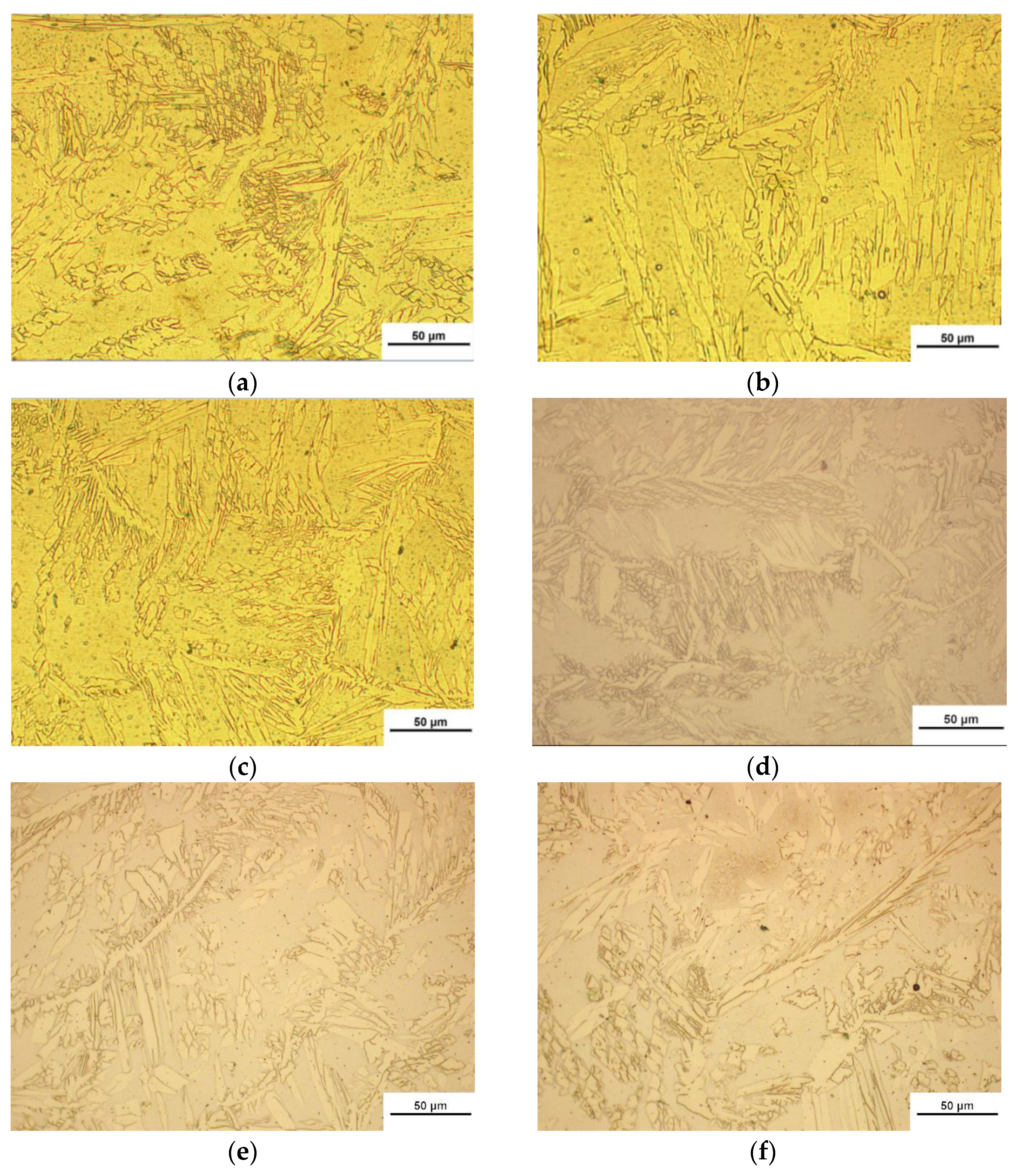
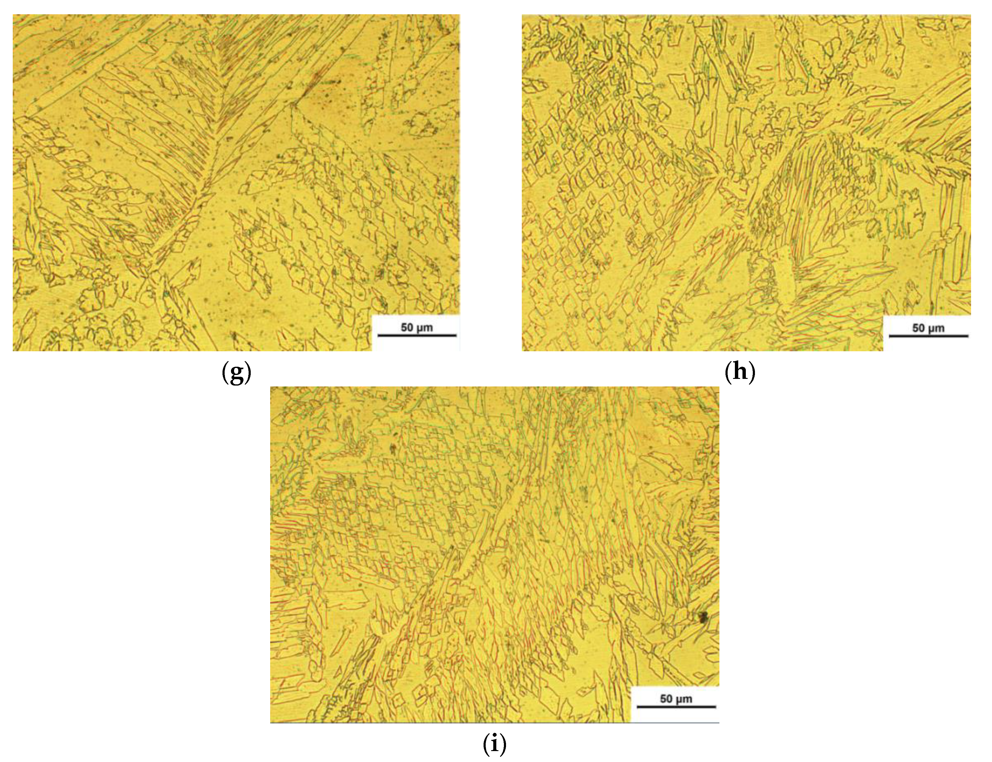
The microstructure of the seam was observed with 50X magnification. The welded seam shows obvious dendritic structures, most of which were austenite. These austenite structures are feathery and amount to a relatively higher proportion. Most austenite gets distributed in the grain boundaries and ferrite grains. It can be seen from
Figure 6 that there are more Wei's body structures in the welded seam; the hardness of the metal was not high, and the brittleness of the metal in the molten pool also increased significantly. Experiment results suggested that the grains of the fusion zones in tests 1#, 2#, and 3# t were obviously coarser than those in tests 4#, 5#, and 6#, and the grains of the fusion zones in tests 7#, 8#, and 9# were coarser than those in tests 4#, 5# and 6#. This was because the flowrates of the additional shielding gas in tests 1#, 3#, and 5# were smaller and so, the flowability of metal was poorer and the residence time of liquid metal was longer, which continued to increase the proportion of austenite in the fusion zone and increased the brittleness of the metal in the molten pool, resulting in the hardness and toughness of the material in 1#, 2#, and 3# tests were worse than those in tests 4#, 5#, and 6#. As the welding speed increased, the grain size of the fusion zone also increased to a certain extent. The reason was that when the welding line energy increased, the corresponding weld cooling rate reduced and the secondary dendrite spacing obviously increased, which easily formed a coarser structure. Moreover, under the influence of line energy, the metal of the welded seam will be in a high-temperature state for a long time and the quantity of heat transferred under the action of the temperature difference also increases, which promoted the migration of the grain boundary [
30].
3.3. Hardness Test Result
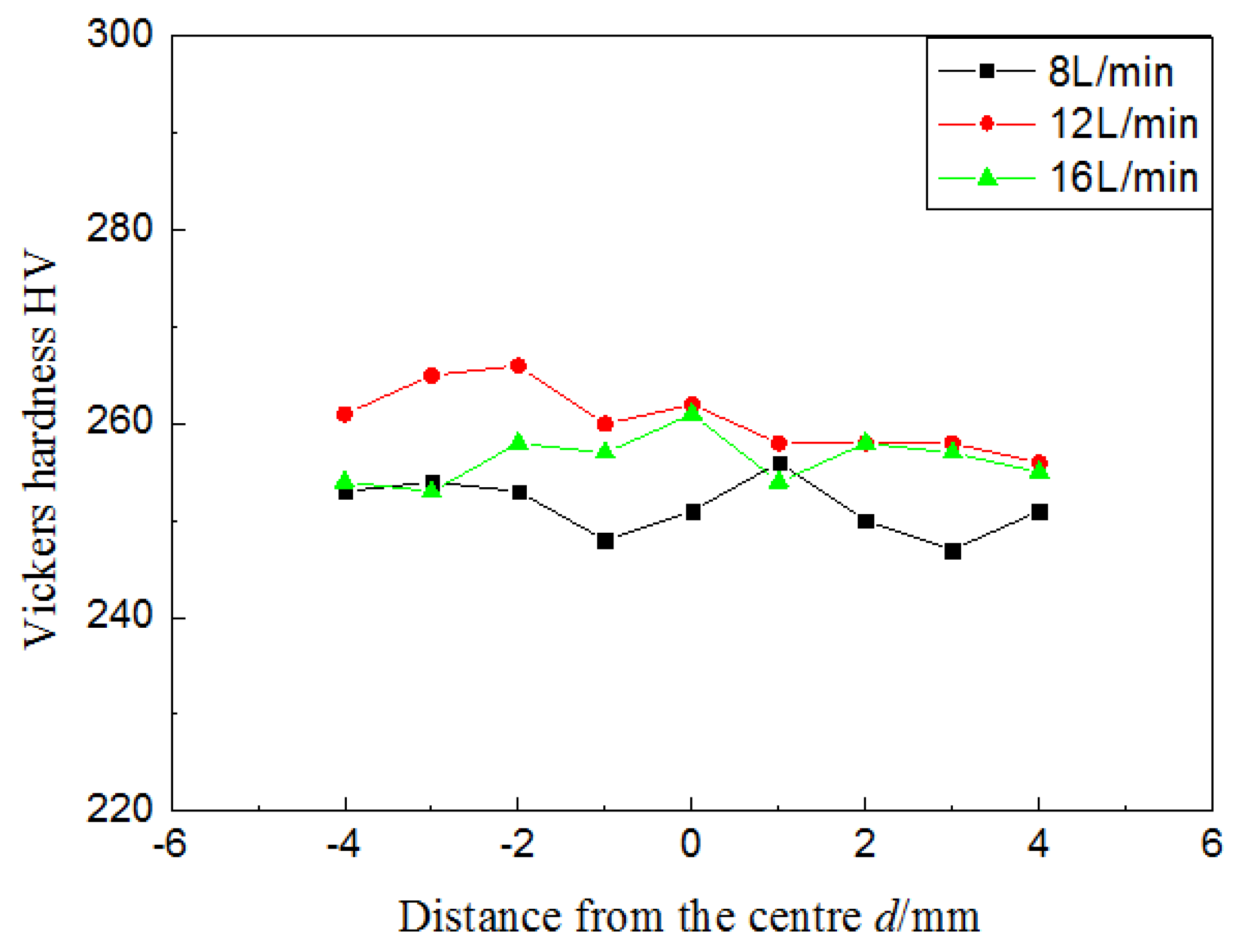
The results of the Vickers hardness test for the seam under additional shielding gas with different flowrates were shown in
Figure 7. It can be seen that the Vickers hardness of the seam formed under the flowrate of 12 L/min was slightly higher than that under the flowrate of 8 L/min, which indicated that an increase in the flowrate of the additional shielding gas was advantageous in increasing the hardness of the joints. This phenomenon occurred because the higher flowrate of the additional shielding gas increased temperature gradient of the joints and accelerated heat dissipation, thereby endowing the joints with a higher hardness. The Vickers hardness of the welded seam under the additional shielding gas flowrate of 12 L/min was slightly higher than that under the flowrate of 16 L/min. This was because the excessive flowrate makes the molten pool depressed under the impact force and the metal flowed downward obviously. Therefore, the liquid-solid transition completed before the metal that bulged toward both sides recover towards the middle region. After complete solidification, the metal becomed a groove which obviously exceeded the actual capacity of the molten liquid pool. Dued to the obvious bulging phenomenon of the metal flowing downward, it was difficult for the portion of the metal to transfer heat to the additional shielding gas. The slower heat dissipation of metal resulted in the coarse seam structure and then led to the lower hardness of the joint.
3.4. Mechanical Properties
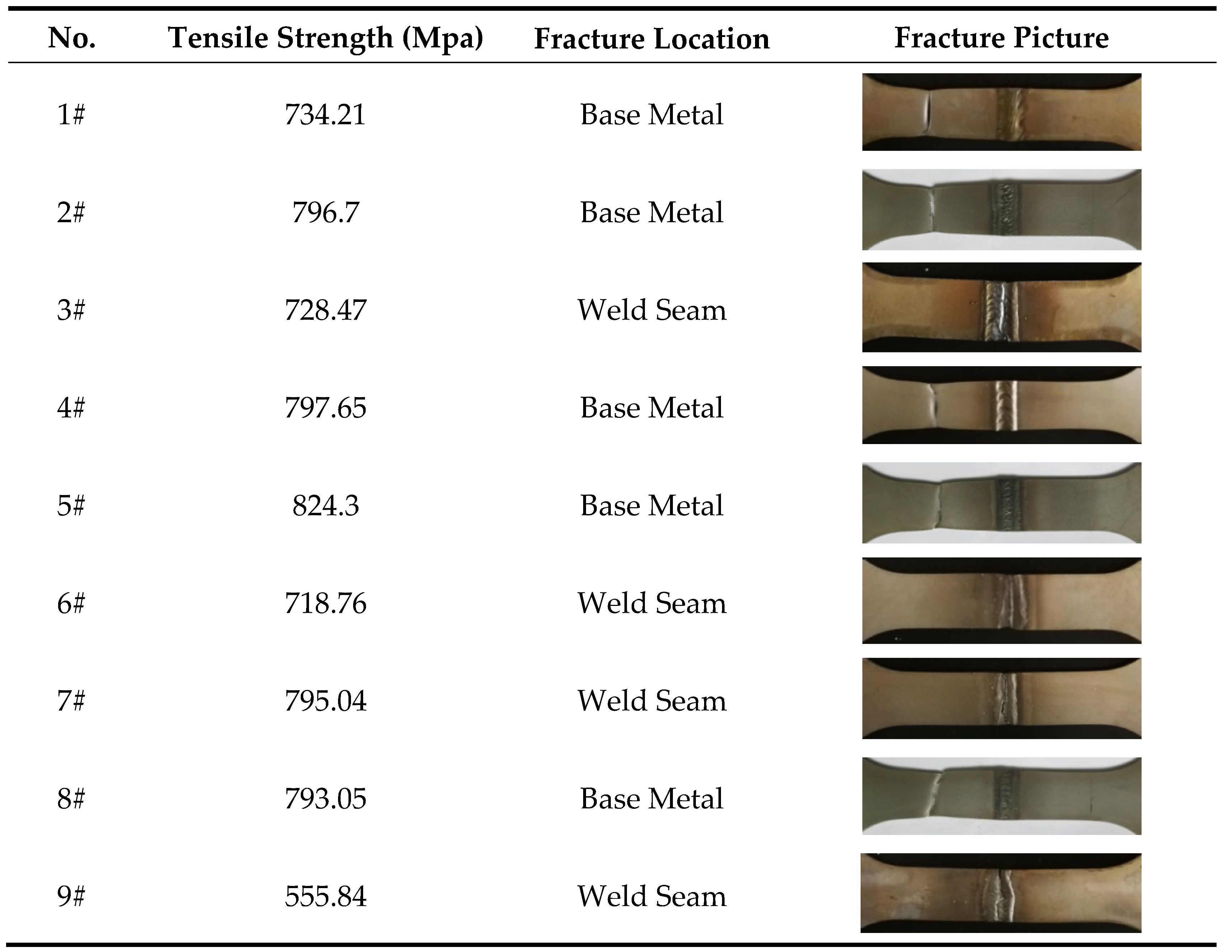
The tensile strength and fracture situations of the seams were shown in
Table 4. The analysis of the test results in
Table 4 indicated that the fracture positions in tests 1#, 2#, 4#, 5#, and #8 all appeared on the side of the base metal and the tensile strengths of the welded seams were higher than those of the base metal, while the fracture positions in tests 3#, 6#, 7#, and 9# appeared at the welded seams indicating that the strengths of obtained welded seams were lower than that of base metal. On considering the fracture positions of the welded seam simultaneously, the analysis indicated that the tensile strength of the welded seam was mainly affected by the cross-section shape of the seam. The seam with lower penetration couldnot withstand the high ultimate load, and so, the fracture possibilities of such positions were also higher. However, the problem did not occur in the tensile test of the seam with better fusion.
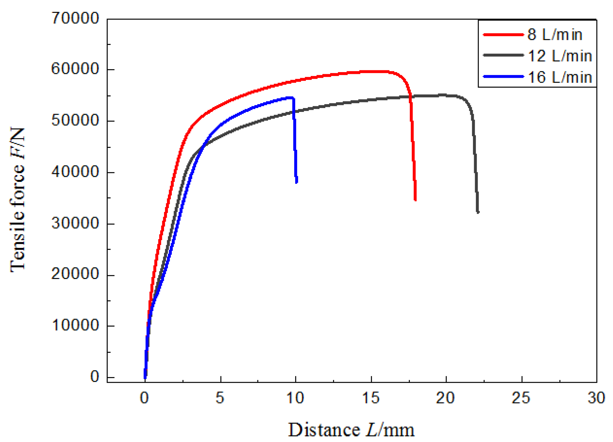
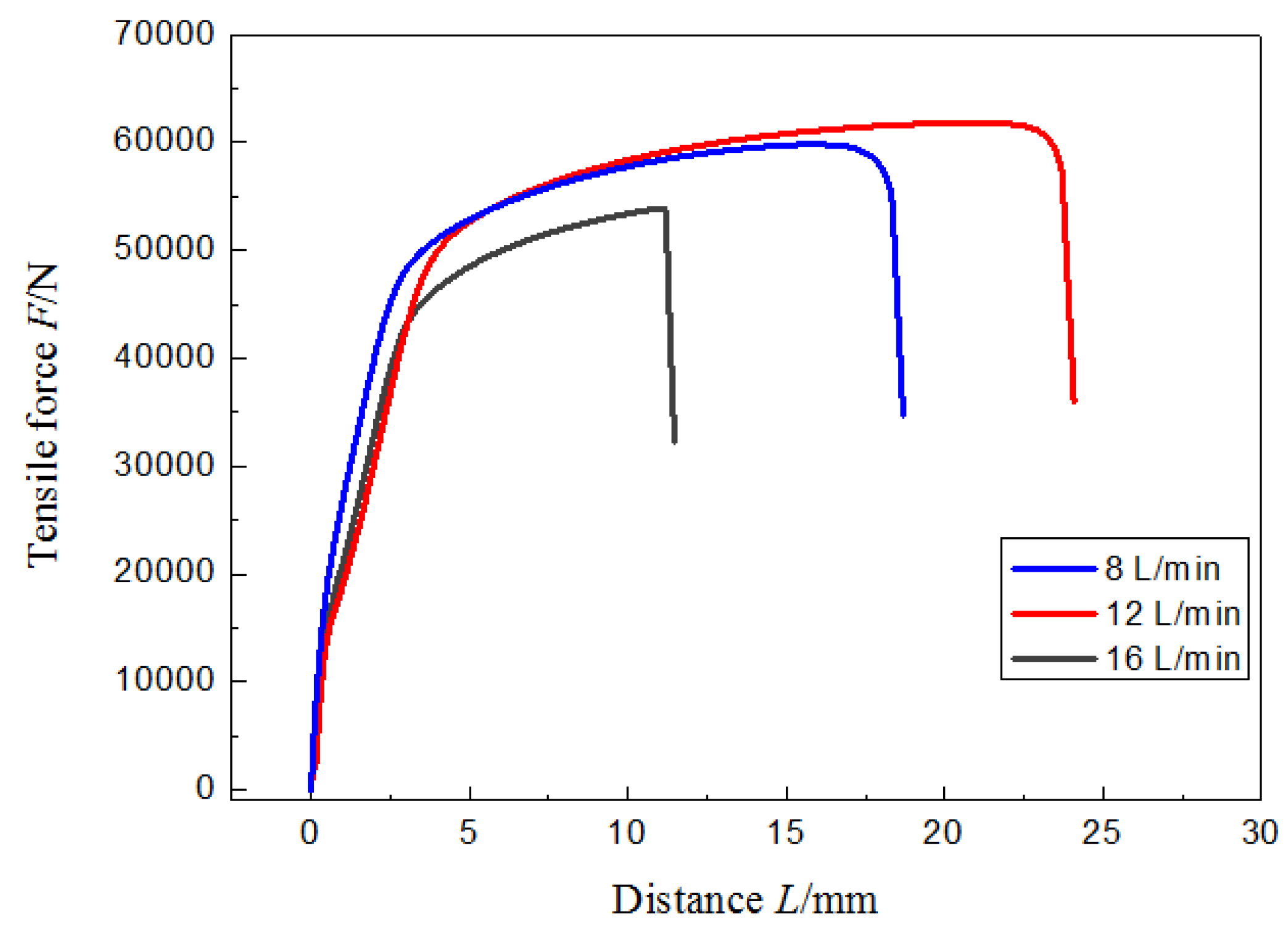
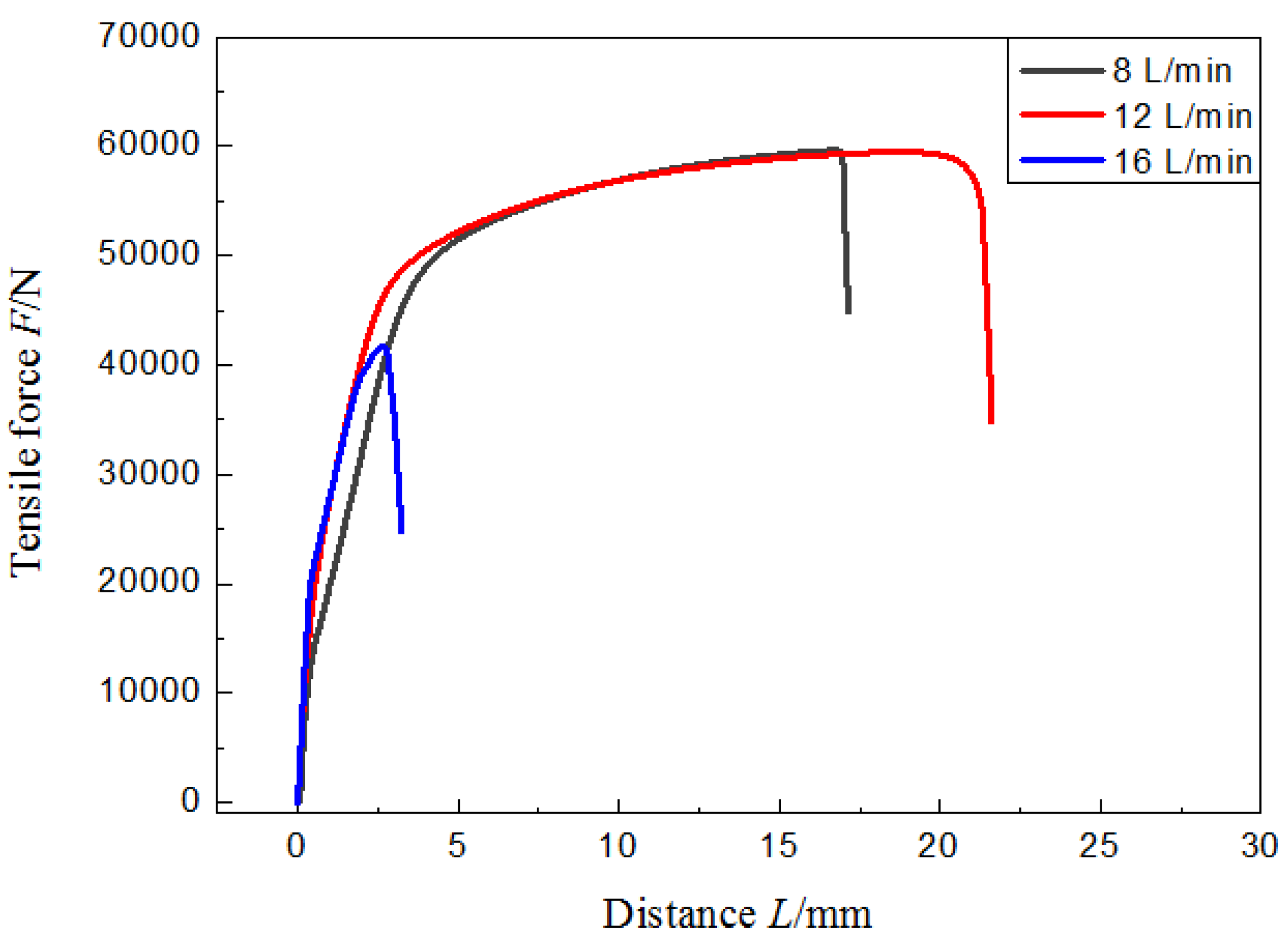
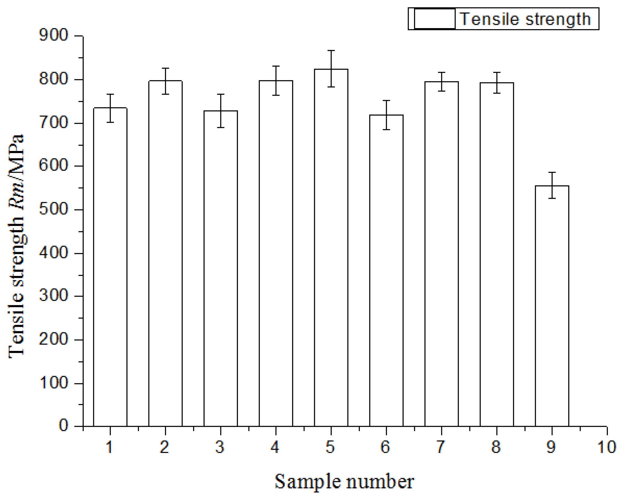
The tensile test results of the joints were shown in
Figure 8,
Figure 9,
Figure 10 and
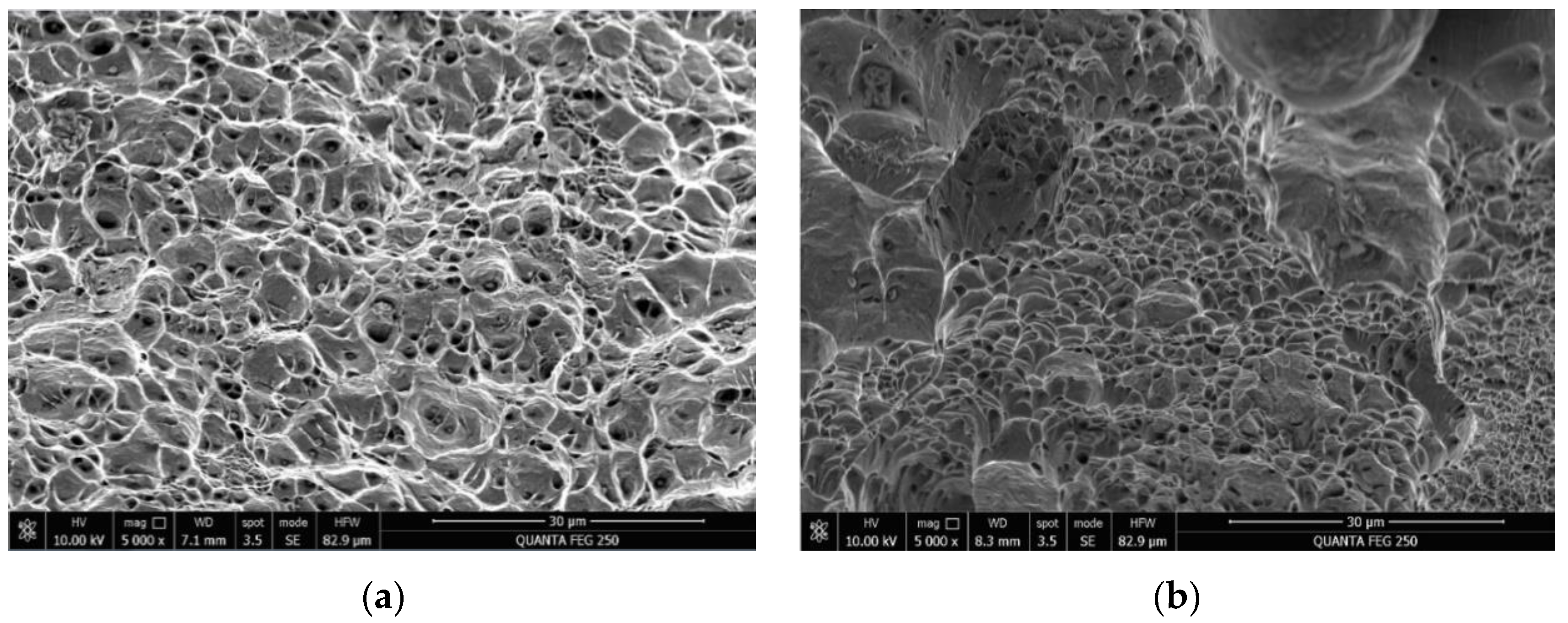
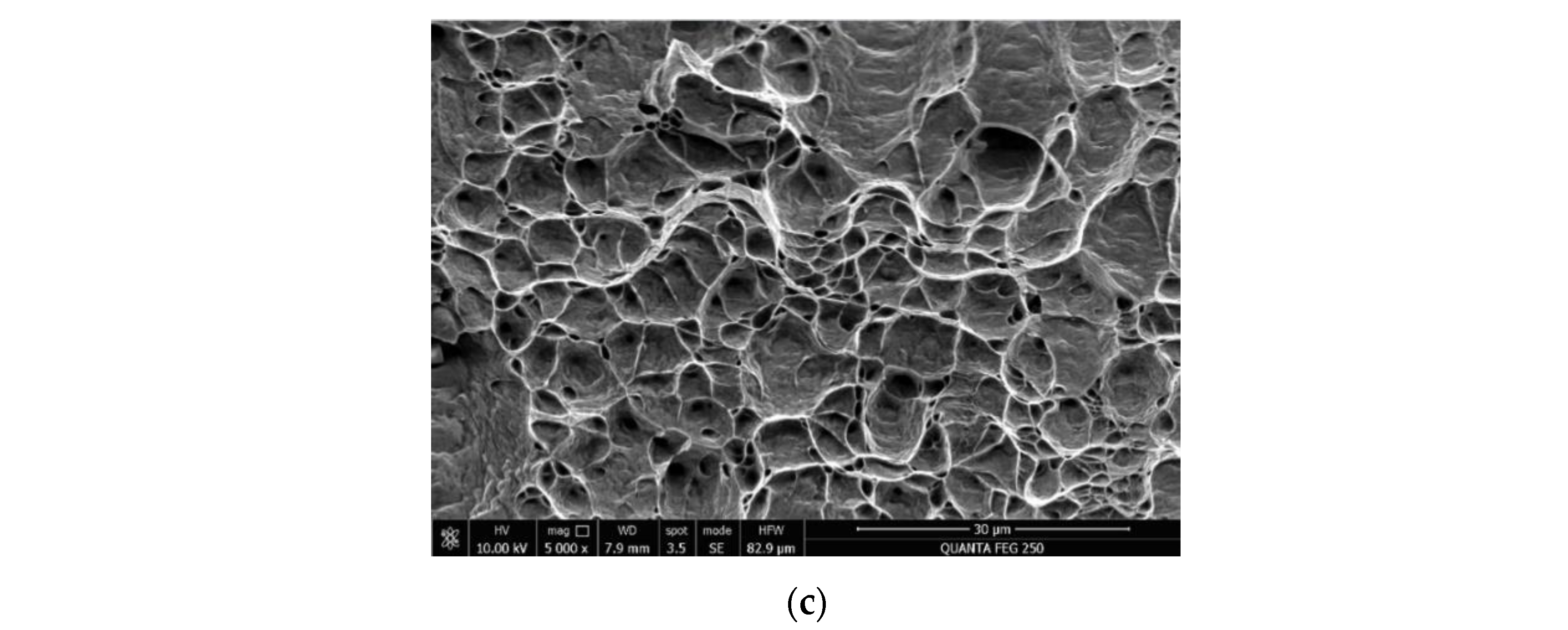
Figure 11. The maximum tensile strength of specimens 1# ~ 9# were 734.21 MPa, 796.7 MPa, 728.47 MPa, 797.65 MPa, 824.3 MPa, 718.76 MPa, 795.04 MPa, 793.05 MPa, and 555.84 MPa, respectively. Under the identical welding current and for welding speeds of 1.6 m/min, 1.8 m/min, and 2.0 m/min, respectively, the joint formed under the flowrate of 12 L/min had the highest tensile strength among the test specimens under different flowrates of 8 L/min, 12 L/min, and 16 L/min. As the welding speed was 2.0 m/min and the flowrates of additional shielding gas were different, the morphologies of the tensile-fractured sections were shown in
Figure 12. The fracture section of the welded seam formed under the flowrate of 8 L/min was the transgranular fracture along the cleavage planes, and thus, could be classed as brittle fracture; the fracture section of welded seam formed under the flowrate of 12 L/min contained a large number of dimples and there was a certain amount of inclusions at the bottom of these dimples [
31], indicating that the fracture belonged to the ductile regime. The fracture section of the seam formed under a flowrate of 16 L/min was a transgranular fracture along the cleavage plane, indicating that it belongs to the brittle fracture.
4. Conclusions
After introducing the additional shielding gas with different flowrates, the twin-wire pulsed GMAW high-speed welding could achieve the following benefits:
(1) Under the appropriate gas flowrate, using an additional protective gas jet could significantly suppress defects such as non-penetration, humping, and undercut formed in high-speed welding, meanwhile it can significantly enhance the welding speed, improve the appearance and mechanical properties of the welded seam.
(2) As the flowrate of the additional shielding gas was 12 L/min, the impact force caused by the jet is optimal for the set of welding parameters, thus resulting in the best improvement of the welded seam.
(3) The impact force generated by the flowrate of 8 L/min is slightly smaller, so the improvement effect is worse than that under the flowrate of 12 L/min. As the flowrate is 16 L/min, over-protection phenomenon of the gas jet occurs on the welded seam, and the welded seam exhibits a grooved morphology so that the middle region is lower and the two sides are higher.
Author Contributions
Conceptualization, Jiaxiang Xue; Writing – original draft, Yu Hu; Supervision, Jiaxiang Xue; Funding acquisition, Yu Hu.
Funding
This research received funding from Major Science and Technology Plan of Hainan Province (Grant No. ZDKJ2021013), Hainan Province Science and Technology Special Fund (Grant No. ZDYF2021XDNY305, ZDYF2023XDNY066), National Key R&D Program of China (Grant No. 2019YFD0900903), Modern agriculture (FISH) industrial technology special fund system(CARS-47-Z16).
Conflicts of Interest
The authors declare no conflict of interest.
References
- Abdo, H.S.; Seikh, A.H. Mechanical properties and microstructural characterization of laser welded S32520 duplex stainless steel. Materials 2021, 14, 5532. [Google Scholar] [CrossRef] [PubMed]
- Zhang, X.Y.; Zha, X.Q.; Gao, L.Q.; et al. Influence of shielding gas on microstructure and properties of GMAW DSS2205 welded joints. Materials 2021, 14, 2671. [Google Scholar] [CrossRef] [PubMed]
- Wang, K.; Shao, C.; Jiao, X.; et al. Investigation on microstructure and properties of duplex stainless steel welds by underwater laser welding with different shielding Gas. Materials 2021, 14, 4774. [Google Scholar] [CrossRef] [PubMed]
- Cui, S.; Pang, S.; Pang, D.; Zhang, Q.; Zhang, Z. Numerical simulation and experimental investigation on 2205 duplex stainless steel K-TIG welded joint. Metals 2021, 11, 1323. [Google Scholar] [CrossRef]
- Hu, Y.; Shi, Y.; Sun, K.; et al. Effect of heat input on the microstructure and mechanical properties of local dry underwater welded duplex stainless steel. Materials 2023, 16, 2289. [Google Scholar] [CrossRef] [PubMed]
- Shi, Y.; Cui, S.; Zhu, T.; et al. Microstructure and intergranular corrosion behavior of HAZ in DP-TIG welded DSS joints. J. Mater. Process. Technol. 2018, 256, 254–261. [Google Scholar] [CrossRef]
- Arabi, S.; Pouranvari, M.; Movahedi, M. Pathways to improve the austenite–ferrite phase balance during resistance spot welding of duplex stainless steels. Sci. Technol. Weld. Join. 2018, 5, 1–8. [Google Scholar] [CrossRef]
- Emami, S.; Saeid, T.; Khosroshahi, R.A. Microstructural evolution of friction stir welded SAF 2205 duplex stainless steel. J. Alloy. Compd. 2018, 739, 678–689. [Google Scholar] [CrossRef]
- Krasnorutskyi, S.; Kipp, C.; Hensel, J.; et al. Metallurgical investigation of electron beam welded duplex stainless steel X2CrNiMoN22-5-3 with plasma nitrided weld edge surfaces. Mater. Test. 2018, 60, 577–582. [Google Scholar] [CrossRef]
- Ye, D.J.; Hua, X.M.; Zhang, J.; et al. Analysis of arc interference and welding stability in twin wire GMAW welding. Int. J. Adv. Manuf. Technol. 2015, 81, 627–633. [Google Scholar] [CrossRef]
- Dong, C.W.; Xue, J.X.; Xu, M.; et al. Effects of additional compensation shielding gas on high-speed pulsed MIG welding seams. Trans. China Weld. Inst. 2015, 36, 85–88. [Google Scholar]
- Hu, Y.; Xue, J.X.; Dong, C.W.; et al. Effect of additional shielding gas on welding seam formation during twin wire DP-MIG high-speed welding. Appl. Sci. 2018, 9, 1658. [Google Scholar] [CrossRef]
- Berna, C.; Juliá, J.E.; Escrivá, A.; et al. Experimental investigation of the entrained droplet velocities in a submerged jet injected into a stagnant water pool. Exp. Therm. Fluid Sci. 2017, 82, 32–41. [Google Scholar] [CrossRef]
- Mordasov, M.M.; Savenkov, A.P.; Chechetov, K.E. Method for analyzing the gas jet impinging on a liquid surface. Tech. Phys. 2016, 61, 659–668. [Google Scholar] [CrossRef]
- Kim, S.Y.; Lee, H.S.; Park, J.H. Deposition of different metallic coatings as repair materials for concrete by using a twin-wire arc thermal spray process. Appl. Sci. 2022, 12, 11874. [Google Scholar] [CrossRef]
- Milz, M.P.; Wirtz, A.; Abdulgader, M.; et al. Fatigue assessment of twin wire arc sprayed and machine hammer-peened ZnAl4 coatings on S355 JRC+C substrate. Materials 2022, 15, 1182. [Google Scholar] [CrossRef] [PubMed]
- Moinuddin, S.Q.; Sharma, A. Arc stability and its impact on weld properties and microstructure in anti-phase synchronised synergic-pulsed twin-wire gas metal arc welding. Mater. Des. 2015, 67, 293–302. [Google Scholar] [CrossRef]
- Wu, K.Y.; He, Z.W.; Liang, Z.Y.; et al. The dynamic behavior of double arc interference in high-power double wire pulsed GMAW. Int. J. Adv. Manuf. Technol. 2016, 88, 2795–2802. [Google Scholar] [CrossRef]
- Ye, D.J.; Hua, X.M.; Xu, C.; et al. Research on arc interference and welding operating point change of twin wire MIG welding. Int. J. Adv. Manuf. Technol. 2017, 89, 493–502. [Google Scholar] [CrossRef]
- Ueyama, T.; Ohnawa, T.; Tanaka, M.; et al. Effects of torch configuration and welding current on weld bead formation in high speed tandem pulsed gas metal arc welding of steel sheets. Sci. Technol. Weld. Join. 2013, 10, 750–759. [Google Scholar] [CrossRef]
- Wu, C.S.; Hu, Z.H.; Zhong, L.M. Prevention of humping bead associated with high welding speed by double-electrode gas metal arc welding. Int. J. Adv. Manuf. Technol. 2012, 63, 573–581. [Google Scholar] [CrossRef]
- Chen, D.S.; Chen, M.A.; Wu, C.S. Effects of phase difference on the behavior of arc and weld pool in tandem P-GMAW. J. Mater. Process. Technol. 2015, 225, 45–55. [Google Scholar] [CrossRef]
- Ueyama, T.; Ohnawa, T.; Tanaka, M.; et al. Effects of torch configuration and welding current on weld bead formation in high speed tandem pulsed gas metal arc welding of steel sheets. Sci. Technol. Weld. Join, 2005, 10, 750–759. [Google Scholar] [CrossRef]
- Ueyama, T.; Ohnawa, T.; Tanaka, M.; et al. Occurrence of arc interaction in tandem pulsed gas metal arc welding. Sci. Technol. Weld. Join. 2007, 12, 523–529. [Google Scholar] [CrossRef]
- Ueyama, T.; Uezono, T.; Era, T.; et al. Solution to problems of arc interruption and arc length control in tandem pulsed gas metal arc welding. Sci. Technol. Weld. Join. 2009, 14, 305–314. [Google Scholar] [CrossRef]
- Sterjovski, Z.; Bayley, C.; Donato, J.; et al. Weld-End solidification cracking in pulsed-tandem gas metal arc welding of naval steels. Weld. J. 2014, 93, 145–152. [Google Scholar]
- Schricker, K.; Baumann, A.; Bergmann, J.P. Local shielding gas supply in remote laser beam welding. J. Manuf. Mater. Process. 2021, 5, 139. [Google Scholar] [CrossRef]
- Bishal, S.; Niraj, P.; Sougata, R.; et al. Altering the supply of shielding gases to fabricate distinct geometry in GMA additive manufacturing. Appl. Sci. 2022, 12, 3679. [Google Scholar]
- Palanisamy, V.; Solberg, J.K.; Moe, P.T. Shielded active gas forge welding of an L80 steel in a small scale shielded active gas forge welding machine. J. Manuf. Mater. Process. 2021, 5, 16. [Google Scholar] [CrossRef]
- Ding, R.C.; Yao, J.; Du, B.R.; et al. Effect of shielding gas volume flow on the consistency of microstructure and tensile properties of 316L manufactured by selective laser melting. Metals 2021, 11, 205. [Google Scholar] [CrossRef]
- Lohse, M.; Trautmann, M.; Füssel, U.; et al. Influence of the CO2 content in shielding gas on the temperature of the shielding gas nozzle during GMAW welding. J. Manuf. Mater. Process. 2020, 4, 113. [Google Scholar] [CrossRef]
Figure 1.
Schematic diagram of the twin wire pulsed GMAW welding under different flowrate of additional shielding gas.
Figure 1.
Schematic diagram of the twin wire pulsed GMAW welding under different flowrate of additional shielding gas.
Figure 2.
Dimensions of test specimens (unit: mm): (a) Draft of plate and all dimensions; (b) Specimen for tensile test.
Figure 2.
Dimensions of test specimens (unit: mm): (a) Draft of plate and all dimensions; (b) Specimen for tensile test.
Figure 3.
Weld depth, weld width and weld D/W ratio.
Figure 3.
Weld depth, weld width and weld D/W ratio.
Figure 4.
Morphology of the weld seam(unit: mm).
Figure 4.
Morphology of the weld seam(unit: mm).
Figure 5.
Metallographic test results of heat-affected zone (HAZ): (a) Metallographic image of HAZ in 1# test, (b) Metallographic image of HAZ in 2# test, (c) Metallographic image of HAZ in 3# test, (d) Metallographic image of HAZ in 4# test, (e) Metallographic image of HAZ in 5# test, (f) Metallographic image of HAZ in 6# test, (g) Metallographic image of HAZ in 7# test, (h) Metallographic image of HAZ in 8# test, (i) Metallographic image of HAZ in 9# test.
Figure 6.
Metallographic test results of weld metal: (a) Metallographic image of fusion zone in 1# test; (b) Metallographic image of fusion zone in 2# test; (c) Metallographic image of fusion zone in 3# test; (d) Metallographic image of fusion zone in 4# test; (e) Metallographic image of fusion zone in 5# test; (f) Metallographic image of fusion zone in 6# test; (g) Metallographic image of fusion zone in 7# test; (h) Metallographic image of fusion zone in 8# test; (i) Metallographic image of fusion zone in 9# test.
Figure 7.
The hardness of Vivtorinox in welded joints.
Figure 7.
The hardness of Vivtorinox in welded joints.
Figure 8.
Comparison of tensile result of weld with different flow rate at 1.6 m/min speed.
Figure 8.
Comparison of tensile result of weld with different flow rate at 1.6 m/min speed.
Figure 9.
Comparison of tensile result of weld with different flow rate at 1.8 m/min speed.
Figure 9.
Comparison of tensile result of weld with different flow rate at 1.8 m/min speed.
Figure 10.
Comparison of tensile result of weld with different flow rate at 2 m/min speed.
Figure 10.
Comparison of tensile result of weld with different flow rate at 2 m/min speed.
Figure 11.
Tensile properties of the welded joints.
Figure 11.
Tensile properties of the welded joints.
Figure 12.
Tensile section diagrams of different additional shielding gas flowrates at welding speed of 2.0 m/min: (a) 8 L/min; (b) 12 L/min; (c) 16 L/min.
Figure 12.
Tensile section diagrams of different additional shielding gas flowrates at welding speed of 2.0 m/min: (a) 8 L/min; (b) 12 L/min; (c) 16 L/min.
Table 1.
Chemical compositions of 2205 and ER2209.
Table 1.
Chemical compositions of 2205 and ER2209.
| Materials |
C |
Mn |
Si |
Cr |
Ni |
Mo |
N |
S |
P |
| ER2209 |
0.025 |
1.6 |
0.3 |
22.5 |
9.5 |
3.1 |
0.16 |
0.01 |
0.025 |
| 2205 |
0.024 |
≤2.0 |
≤1.0 |
22-23 |
4.5-6.5 |
3.0-3.5 |
0.15-0.2 |
≤0.02 |
≤0.03 |
Table 2.
Main welding parameters of weld process.
Table 2.
Main welding parameters of weld process.
| No. |
Flowrate of Additional Shielding Gas L/min |
Weld Speed V/cm/min |
Welding Peak Current Ip/A |
Welding Base Current Ib/A |
Double pulse frequency f/Hz |
| 1# |
8 |
160 |
350 |
120 |
3 |
| 2# |
8 |
180 |
350 |
120 |
3 |
| 3# |
8 |
200 |
350 |
120 |
3 |
| 4# |
12 |
160 |
350 |
120 |
3 |
| 5# |
12 |
180 |
350 |
120 |
3 |
| 6# |
12 |
200 |
350 |
120 |
3 |
| 7# |
16 |
160 |
350 |
120 |
3 |
| 8# |
16 |
180 |
350 |
120 |
3 |
| 9# |
16 |
200 |
350 |
120 |
3 |
Table 3.
The weld shape and joints section.
Table 3.
The weld shape and joints section.
Table 4.
Tensile strength of weld joint.
Table 4.
Tensile strength of weld joint.
|
Disclaimer/Publisher’s Note: The statements, opinions and data contained in all publications are solely those of the individual author(s) and contributor(s) and not of MDPI and/or the editor(s). MDPI and/or the editor(s) disclaim responsibility for any injury to people or property resulting from any ideas, methods, instructions or products referred to in the content. |
© 2023 by the authors. Licensee MDPI, Basel, Switzerland. This article is an open access article distributed under the terms and conditions of the Creative Commons Attribution (CC BY) license (https://creativecommons.org/licenses/by/4.0/).
