Preprint
Article

Analysis of Inverter Circulating Current and Magnetic Potential For flux-weakening Drive of BLDCM

Altmetrics

Downloads

137

Views

10

Comments

0

A peer-reviewed article of this preprint also exists.

This version is not peer-reviewed

Submitted:

24 April 2023

Posted:

24 April 2023

You are already at the latest version

Alerts
Abstract
Permanent magnet brushless DC motor (BLDCM) is usually controlled by six step commutation method, and flux-weakening method is used to make the motor run higher above the base speed. For now, it is considered that the weak magneto-electric angle range is 0-pi/3, and that of deep weakening is pi/3-pi/2. In the field- weakening control, the forward shift of commutation point will form inverter circulating current in the three-phase bridge of inverter and the stator winding of the motor. In this paper, the principle of inverter circulating current formed by inverter is analyzed. Through magnetic potential analysis and Simulink simulation, it is concluded that flux-weakening control will generate inverter circulating current in the inverter and motor stator winding. The inverter circulating current affects the magnetic potential of motor, and magnetic potential will move to the rotating direction of motor rotor. When the forward shift angle of inverter commutation point is 0-pi/6 electrical angle, the movement amplitude of current circulating current of inverter is less than pi/6, which plays the role of weakening magnetic field and driving effect; when the forward moving angle is pi/6-pi/3, the movement amplitude of inverter circulating current exceeds pi/6, which plays the role of magnetic weakening and braking. When the braking effect occurs, the reverse torque will appear, resulting in the decrease of motor torque and efficiency. Therefore, the range of weak magneto-electric angle should be between 0-pi/6.
Keywords: 
Subject: Engineering  -   Electrical and Electronic Engineering

Introduction

The permanent magnet brushless motor(BLDCM) is a trapezoidal wave brushless motor controlled by the six-step commutation method. It has the advantages of simple structure, good speed regulation performance, and high efficiency. With the development of various drive and control technologies of DC permanent magnet brushless motors, DC permanent magnet brushless motors have begun to be widely used in various high-performance fields [1,2,3]. Limited by the back electromotive force, when the permanent magnet brushless DC motor is used at high speed and higher than the base speed, it is necessary to use the advanced trigger angle to control the permanent magnet brushless motor field weakening[4]. When the six-step commutation brushless motor runs normally, the angle at which the stator magnetic potential leads the rotor magnetic potential varies between pi*2/3-pi/3, and the average lead angle is pi/2, which does not produce field weakening[5,6]. At present, in the design of the motor field weakening control algorithm, it is considered that the direction of the magnetic potential generated by the stator remains unchanged, and the strength of the field weakening is linearly adjusted through the output lead angle. When the field weakening angle exceeds pi/3, the stator magnetic potential will lead the rotor magnetic potential pi*2/3+pi/3 = pi angle, resulting in a braking effect, so the maximum field weakening angle should be less than pi/3[7,8]. Literature[1] believes that field weakening will cause the effective current to increase. Considering the continuous working current limitation of motor operation, the leading conduction angle should not exceed pi/6 electrical angle. The conclusion of the literature[3]is: the leading conduction angle is an effective method to realize the weakening of permanent magnet brushless motor. In the literature[5], using the space magnetic potential method to analyze the operating state of the brushless motor, the weakening speed regulation performance and torque change of the leading conduction angle 0-pi/3 and pi/3-pi/2 motors are analyzed respectively. Literature[7,8]believes that in the field weakening control, the traditional drive topology circuit will generate an inverter circulating current in the non-conducting phase, and the torque generated by the inverter circulating current is negative, which acts as a brake. Then a new inverter topology that eliminates the current circulating current of the inverter is proposed. In this article, it is believed that the inverter circulating current is a phenomenon formed by the back electromotive force, the freewheeling diode, and the power tube that is turned on in advance during the field weakening operation of the motor. The inverter circulating current will cause the stator magnetic potential to change, but the stator magnetic potential changes How to affect the operation of the motor still needs further analysis. The main work of this paper is to carry out the magnetic potential analysis and simulink simulation when the permanent magnet brushless motor is running at weakening, and analyze the influence of the inverter circulation on the magnetic potential and the influence of the magnetic potential on the motor torque. Finally, it is concluded that the permanent magnet brushless DC motor is turned on in advance in the field weakening control mode, the magnetic potential of the motor moves forward nonlinearly, and the weak magnetic flux is mainly generated by the inverter circulating current, which is 0-pi/6 Within the angle, the inverter circulating current has more field weakening effect and less driving effect; in the pi/6-pi/3 electrical angle, the inverter circulating current has more field weakening effect and less braking effect. Cause the motor efficiency to drop.

1. Inverter circulating current under field weakening of permanent magnet BLDCM

1.1. The generation mechanism of field weakening inverter circulation

The stator winding of the motor is an inductive device, and there must be a freewheeling path when it is turned off. Therefore, the freewheeling diode is a necessary device for inductive load driving. The inverter circulating current caused by the freewheeling diode should be taken into account when the motor is weakened[9,10]. When the permanent magnet brushless motor performs field weakening speed regulation, the conduction angle will be advanced to the range of 0-pi/3. The back EMF and field weakening of a brushless motor are shown in Figure 1: Under normal driving, the output voltage of the driver is in phase with the back EMF; in field weakening control, the non-conducting phase will be closed in advance and the conducting phase will be shut off in advance. On the rising or falling edge of the non-conducting phase, the resulting inverter circulating current is also different. In Figure 1, it is represented as a state and b state, which are B+A-CZ converted into C+A-BZ and A respectively +B-CZ is converted to A+C-BZ. In the following, phase C is regarded as the non-conducting phase, and the circulating currents generated by the rising and falling edges of the back electromotive force are analyzed respectively[11,12].
For star-connected three-phase windings, the back EMFs of the three-phase windings are marked as ea, eb, and ec, and the neutral point N voltage is 0. The direction of the back EMF is positive from the neutral point to the head end, and from the head end to the middle The sex point is negative. In the two selected phases, |ea|=|eb|, ec are changed from ea to -ea and from -ea to ea,respectively. In electrical angle, this change process is 60 degrees, which is pi/3. Therefore,ec can be expressed as formula (1) and formula (2): In the state a in Figure 1, as the lead conduction angle increases, the back electromotive force decreases from ea along the red diagonal line to -ea: the lead conduction angle t has a range of (0-pi/3):
e c = e a e a t p i / 6
In state b in Figure 1, with the increase of the leading conduction angle, the back EMF increases from -ea to ea along the blue diagonal line, and the leading conduction angle t is in the range (0-pi/3):
e c = e a + e a t p i / 6

2. Further analysis of inverter circulation

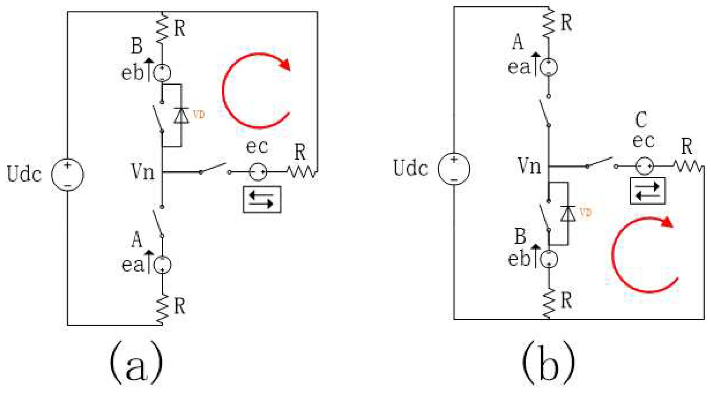
The inverter circuits corresponding to the back electromotive force corresponding to the box parts a and b in Figure 1 are shown in Figure 2, where Udc is the DC power supply, R is the three-phase stator winding, and ea, eb, and ec are the reverse of the three windings. Electromotive force. In Figure 2a, the winding B is connected to the positive pole of the power supply Udc, the winding A is connected to the negative pole, and the winding C is turned on and connected to the positive pole in advance to form an inverter circulating current of the upper arm winding B, which flows through the winding B, the bus positive, the winding C and the neutral point; In 2b, the winding A is connected to the positive pole of the power supply Udc, the winding B is connected to the negative pole, and the winding C is turned on and connected to the negative pole in advance to form the lower bridge arm winding B inverted circulating current, which flows through the winding C, the bus negative, the winding B and the neutral point. In the range of 0-pi/6 degree of lead angle, in the case of a and b, it is the circulating current of the upper bridge arm and the circulating current of the lower bridge arm respectively, and the freewheeling diode is passed in the forward direction[13,14].
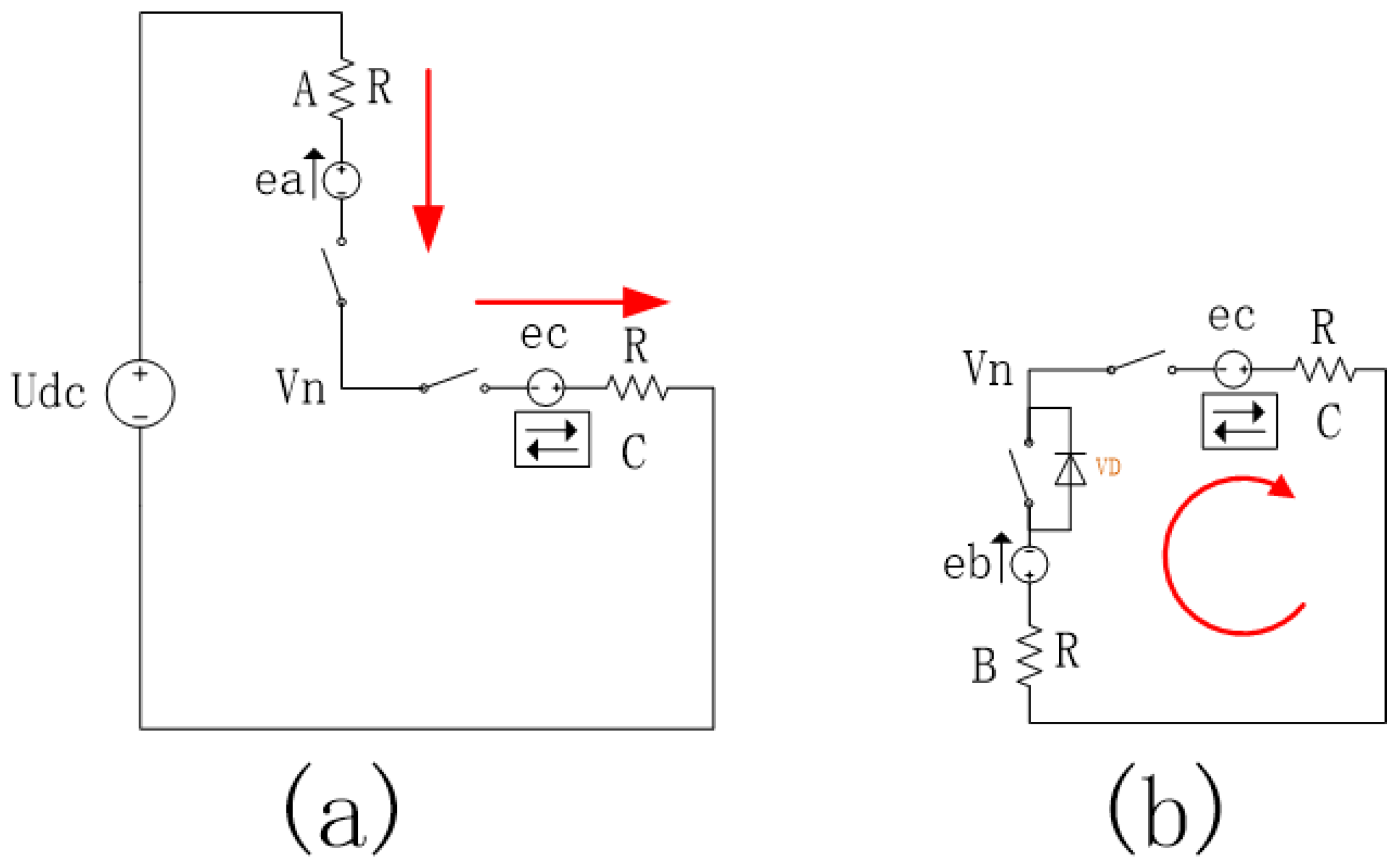
According to Kirchhoff’s current theorem and further analysis of the inverter circulation from Figure 2b, the circuit of Figure 2b can be decomposed into Figure 3:
List the branch current in formula (3)
I a = U d c e a + e c 2 R I b = e c e b V d 2 R I c = I a + I b e b = e a e c = e a + e a t p i / 6
In formula (3), Ia, Ib, and Ic are the currents in the three-phase winding; Vd is the voltage drop of the freewheeling diode conduction tube; Vn is the neutral point voltage; R is the equal three-phase winding resistance; ea, eb, ec is the back electromotive force of the three-phase winding, |ea|=|eb|; t is the leading conduction angle, and the value range is (0 pi/3). Eliminate the neutral point voltage Vn from the formulas (1), (2) and (3), and obtain the formula (4) of the three-phase currents Ia, Ib, Ic:
I a = ( U d c 2 e a ) + e a t p i / 6 2 R I b = e a t p i / 6 V d 2 R I c = ( U d c 2 e a ) + 2 e a t p i / 6 V d 2 R
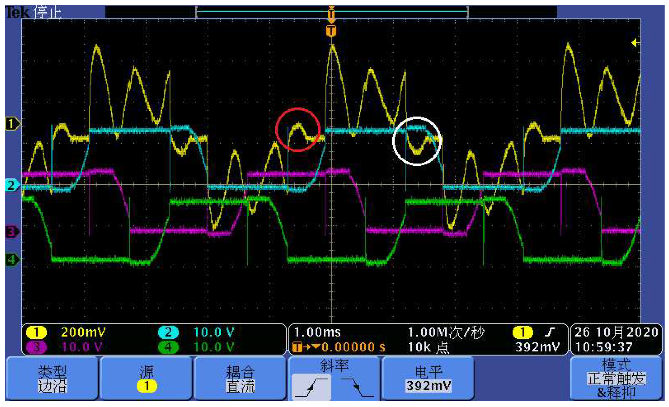
From formulas 3 and 4, it can be concluded that the circulation generation condition is ec-eb > Vd. Calculate and design the inverter circulating current verification experiment according to the above formula: the number of pole pairs of the motor is 4, the power supply voltage is 14V, and there is no load. When the field weakening angle is Pi/6, the average running current is about 0.8A, and the speed is about 3950 rpm. The inverter circulation generated by the motor winding is observed as shown in Figure 4. In Figure 4, the yellow line of channel 1 is the stator current collected by the current probe, and the other three channels are three-phase stator voltage signals; blue is the voltage of the current phase, and purple and green are the phase voltages of the other two phases. The white circle corresponds to the reverse inverter circulating current caused by the positive connection of the green phase of Channel 4 to the busbar in advance, and the red circle corresponds to the inverter circulating current caused by the negative connection of the green phase of Channel 4 to the busbar in advance.

3. The combined magnetic potential analysis of the inverted circulating current and the early conduction.

3.1. Derive the resultant magnetic potential generated by the current from the three-phase current.

In the above formula definition, the angle between the three-phase currents Ia, Ib, and Ic is a distribution of 120 degrees. When the influence of the rotor magnetic potential is not considered, the composite magnetic potential Ff of the three-phase current can be expressed as formula (5):
F f = 2 I a + I b + I c 2 i + s q r t 3 2 ( I b + I c ) j
Substituting formula (4) into formula (5), formula (6) is obtained:
F f = 3 2 ( U d c 2 e a ) + e a t p i / 6 2 R i s q r t 3 2 ( U d c 2 e a ) + 3 e a t p i / 6 2 R j
The angle of Ff can be expressed as formula (7):
θ = a t a n ( F f j F f i ) = a t a n 1 s q r t 3 ( U d c 2 e a ) + e a t p i / 6 ( U d c 2 e a ) + 3 e a t p i / 6
Analyzing the formula (7), the magnitude of the magnetic potential synthesized by the inverter circulating current is related to the back electromotive force ea, the weak magnetic lead angle t, and the diode conduction voltage drop Vd. The back EMF has the greatest impact. When the back EMF satisfies Udc=2ea, the magnetic force direction θ formed by the circulating current is the most advanced; when the back EMF is 0, the magnetic force angle is close to 0. The weak magnetic lead angle and the voltage drop of the diode pass tube have little effect.

3.2. The influence of the circulation on the resultant magnetic potential

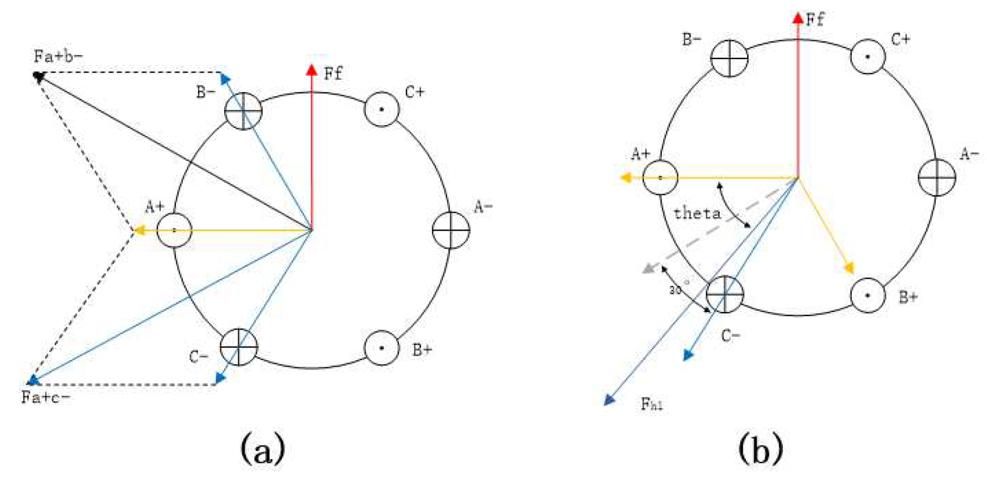
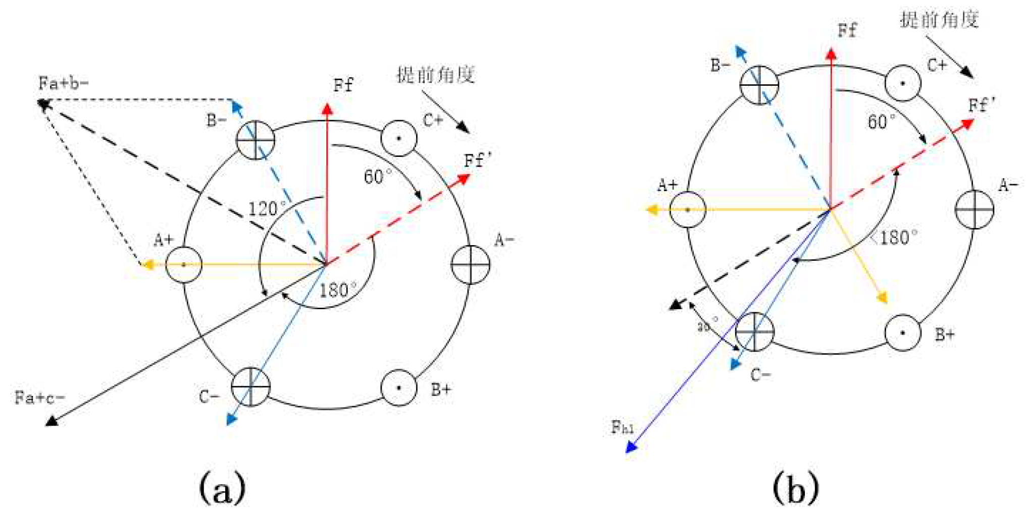
Figure 5a shows the direction of the magnetic potential when the permanent magnet brushless motor commutates when the reverse conversion flow is not considered. In Figure 5, the magnetic potential of the rotor is Ff, the direction is pi/2, the conduction state of the MOS tube of the drive bridge is switched from A+B- to A+C-, and the magnetic potential is from the combined magnetic potential of phase A and phase B Fa+b -Switch to the resultant magnetic potential Fa+c- of phase A and C, the direction of Fa+b- is 5*pi/6, the direction of Fa+c- is 7*pi/6, the angle between the two is pi/3. During normal commutation, the angle between the stator magnetic potential and the rotor magnetic potential changes from pi/3 to pi*2/3, which continues to drive the rotor to rotate. In the current field weakening control algorithm, it is considered that the direction of the composite magnetic potential remains unchanged, only related to the state of the switch tube, and it is regarded as the output angle of the field weakening control[15]. Fig. 5b is a schematic diagram of the synthetic magnetic potential generated by adding the circulating current. It can be deduced from formulas 8 and 9 that the resulting synthetic magnetic potential is close to the magnetic potential generated by the C phase alone, as shown in the red vector Fh1 in Fig. 4b. The resultant magnetic potential is related to the lead angle. The larger the lead angle, the closer to the phase C position. With the movement of the rotor, the inverter circulating current gradually decreases, and the resultant magnetic potential moves counterclockwise to the direction of the AC phase resultant magnetic potential Fa+c-, and stays at the Fa+c- position after the end of the field weakening, as shown in Figure 5b. Shown by the gray dotted line.

3.3. The field weakening effect and braking effect of the inverter circulation.

When the circulation is not considered, the generated magnetic potential is the composite magnetic potential of phase A and phase C, and the direction points to the 7*pi/6 position. Permanent magnet brushless motors commutate at pi/3 intervals. Therefore, the field weakening angle is less than pi/3, and the field weakening angle will only increase the degree of field weakening, and no reverse braking effect will occur. As shown in Figure 6a, the solid line Ff is the position of the rotor magnetic potential when there is no field weakening, and the dashed line Ff’ is the relative backward position of the rotor magnetic potential when the weak magnetic field moves forward by pi/3. At this time, the driving magnetic potential is leading The pi angle of the rotor magnetic potential does not produce driving torque and braking torque. When considering the circulation, the resultant magnetic potential will drift forward, and the generated magnetic potential is between 7*pi/6 and 8*pi/6. When the circulation is larger, it is closer to the direction of 8*pi/6, as shown in Figure 6b. As shown in Fhl, the field weakening may exceed pi/6. After the composite magnetic potential Fhl leads the rotor magnetic potential Ff’ by the angle of pi, the motor braking effect will be produced, and the braking effect will disappear after the rotor rotates for a certain distance. The braking effect is produced by the circulating current, which will cause the power consumption of the motor to increase and the torque and efficiency to decrease[16].
From formula (7), the angle between the stator magnetic potential and the phase A magnetic potential can be calculated. In Figure 5, the angle between the phase A magnetic potential and the rotor magnetic potential is pi/2, so the rotor is weaker The angle between the magnetic potential and the stator magnetic potential can be expressed as Equation 8:
θ 2 = p i / 2 + θ
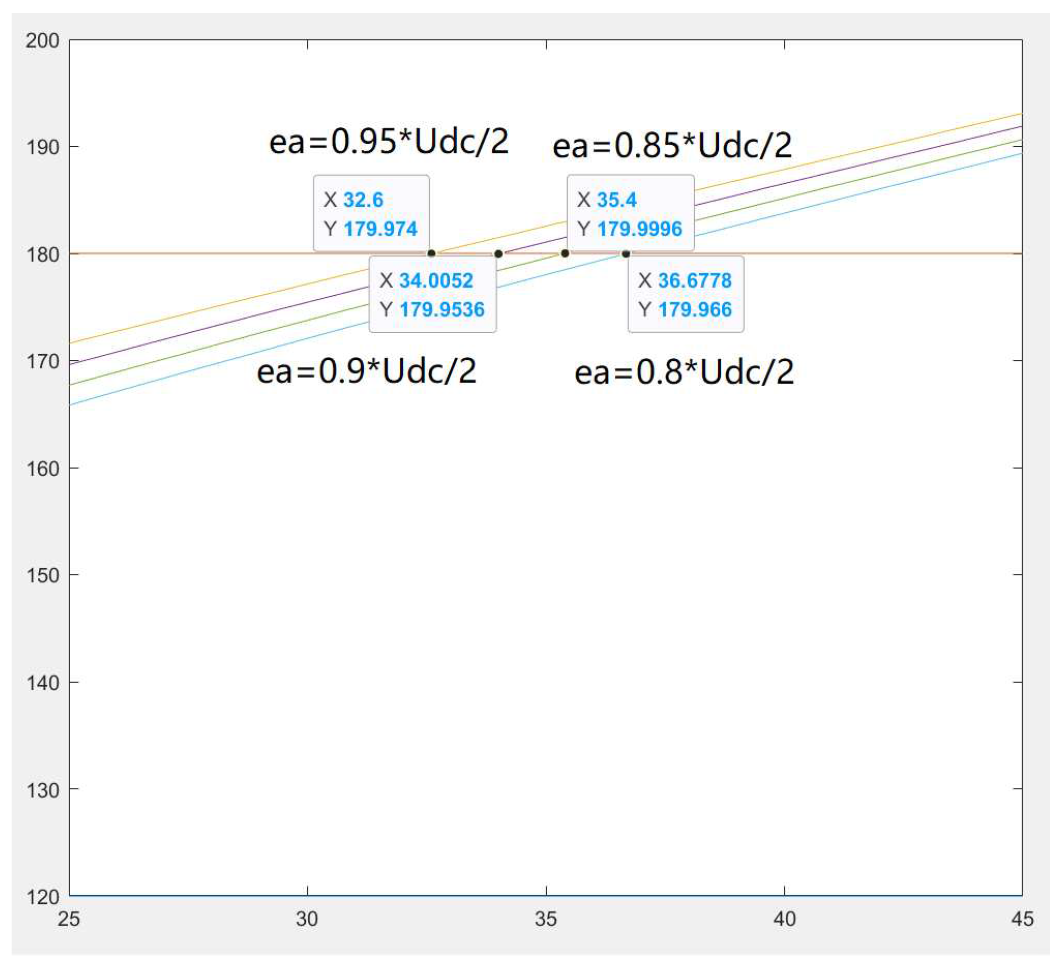
The angle of θ 2 is related to the magnitude of the back-EMF ea and the forward voltage drop of the freewheeling diode Vd. When Vd=0.4V, the relationship between θ 2 and ea and t can be drawn, and the following Figure 7 can be obtained:
Figure 7 shows that when the field weakening angle exceeds pi/6 (30 degrees), θ 2 will be greater than pi, that is, the stator magnetic potential leads the rotor magnetic potential by 180 degrees, and the braking effect appears; Figure 7 also shows that the magnitude of the back EMF is opposite to The variable circulating current has an effect. The closer the back EMF is to 1/2 of the power supply voltage, the earlier the braking effect appears.

4. Matlab simulation model and result verification

4.1. Simulation model

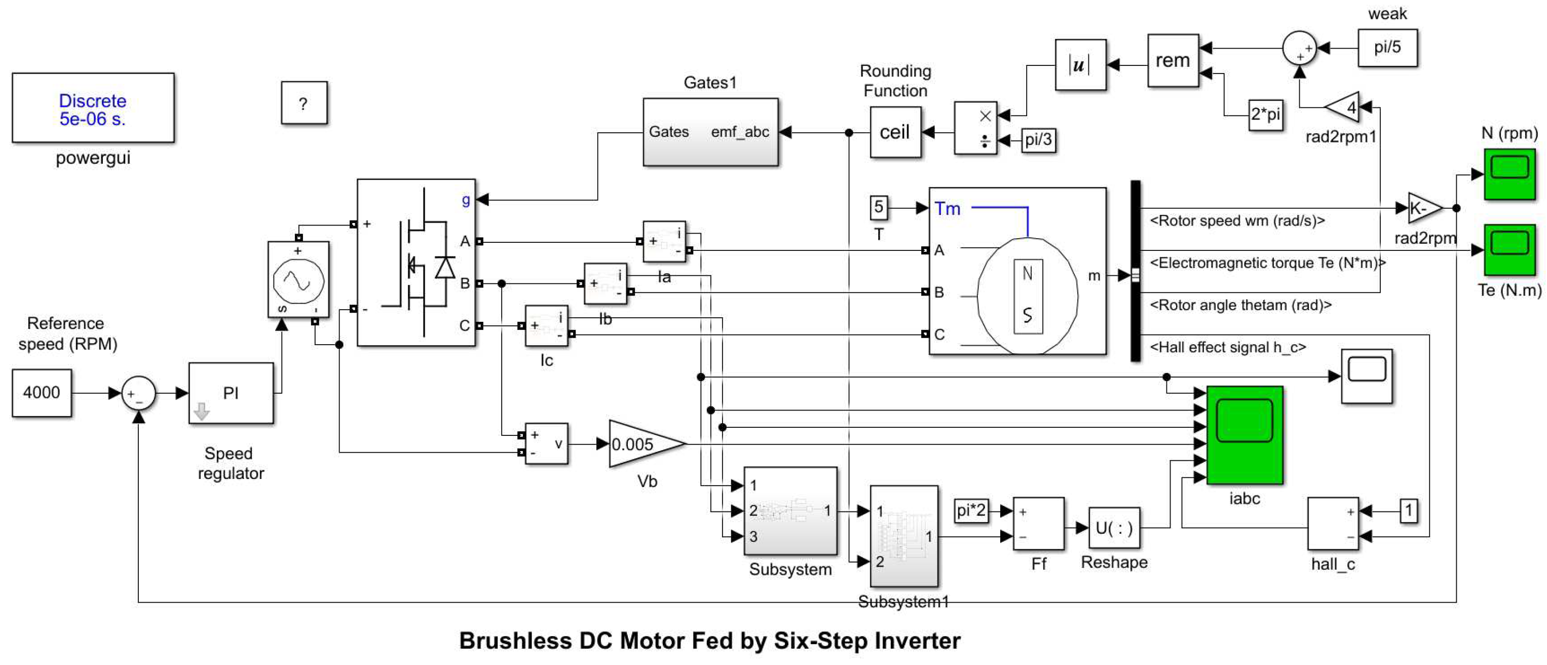
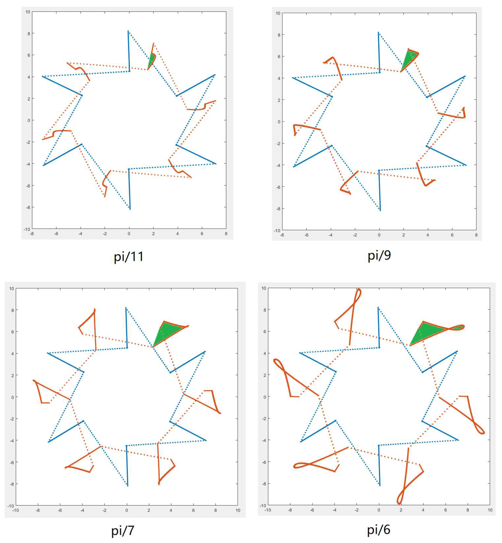
We have verified the theoretical derivation of the previous section of this article in the software matlab R2019a, using the matlab sample "Brushless DC Motor Fed by Six-Step Inverter", and modified the sample, adding the weak magnetic adjustment module and the synthetic magnetic potential calculation The model of the module is shown in Figure 8. The results of the model operation are basically in line with the formula derivation in Section 3: When the field weakening angle is in the range of pi/11 to pi/3, an obvious reverse circulating current can be observed, and the resultant magnetic potential is ahead of the weak magnetic potential under no circulating current. Setting of unmodified sample model parameters: input speed: 4000, exceeding the motor base speed; voltage source 500V; set motor torque T=5. The motor is driven by a six-step method. Affected by the stator inductance, the current shows an upward trend after turning on [17]. The current waveforms of two complete cycles are shown in Figure 9a. The calculation of the composite magnetic potential is formula (5). In Figure 9b, the direction of the composite magnetic potential is expressed as the angle of the magnetic potential (red line), which are respectively pi/6, pi/2, pi*5/6, pi*7 /6, pi*3/2, pi*11/6. It can be seen that the magnetic potential is a horizontal straight line in each conduction phase, that is, the direction of the magnetic potential is constant. The phase is commutated every pi/3 electrical angle, and the magnetic potential moves forward by pi/3[18].

4.2. The sample model is modified to field weakening control and operating results

The modification of the sample model is divided into two parts:

4.2.1. Change of field weakening angle

1) Lead the rotor angle <Rotor angle thetam> from the motor; 2) Correct the number of magnetic pole pairs (gain=4); 3) Add the field weakening angle and sum; 4) Then obtain the current electrical angle through the 2*pi remainder operation; 5) The electrical angle is calculated by pi/3 to obtain the current phase of the 6-step drive.

4.2.2. Solving the magnetic potential

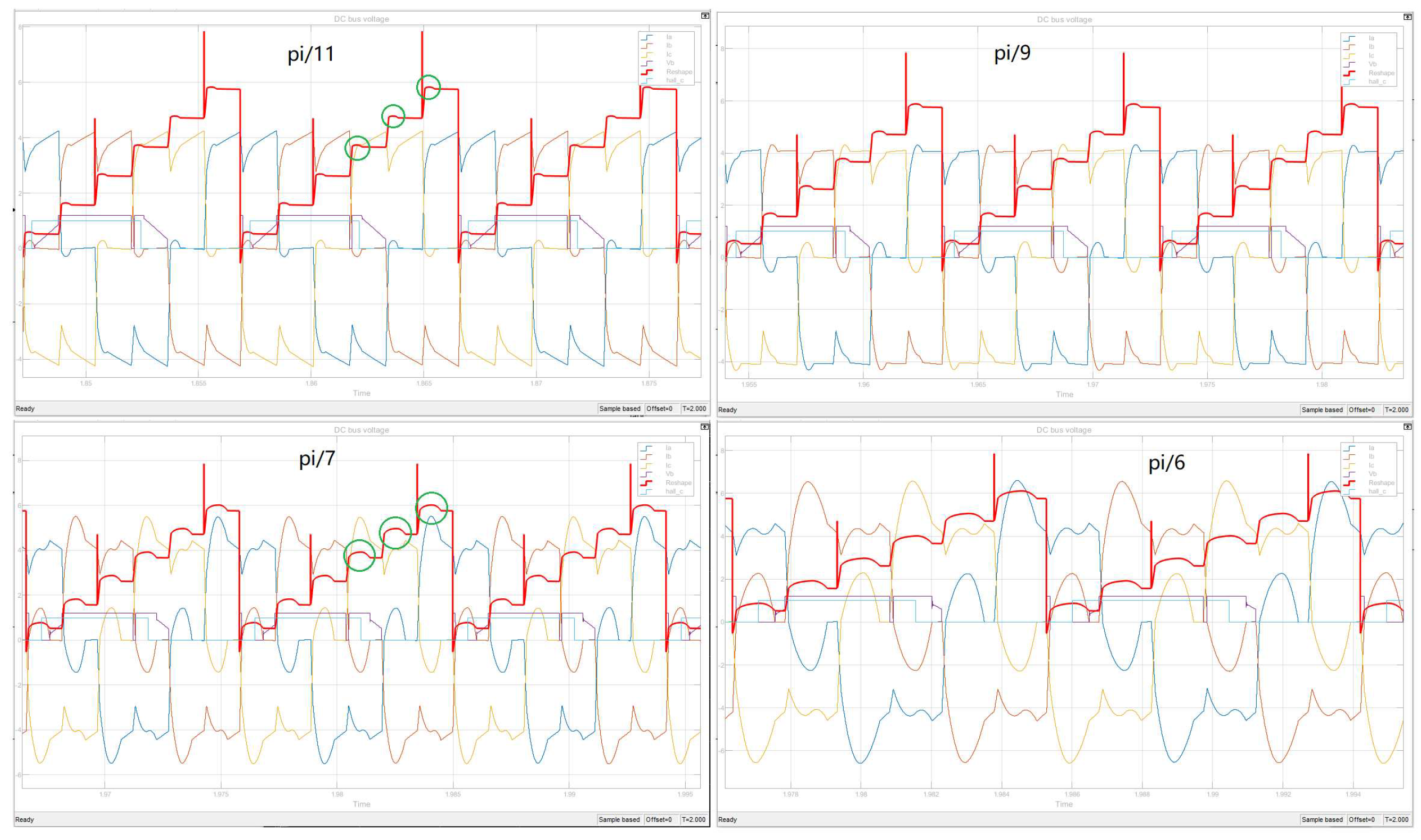
According to the three-phase current and the current driving angle, the direction of the magnetic potential in the driving coil is calculated. Divided into two parts: 1) Collect the three-phase current, and convert the three-phase current into Fx and Fy in the static coordinate system through Clark transformation. 2) Convert Fx and Fy to Ff and use an oscilloscope to observe the image. Under different field weakening angles, the single-phase current waveform and synthesized magnetic potential collected by simulink’s oscilloscope module are shown in Figure 10. When the field weakening angle increases from pi/11 to pi/6, the amplitude and width of the inverter circulation Will increase [19,20], and it is also obvious to convert it into a composite magnetic potential.
The green circle in Fig. 10 marks the beginning of each phase as the weak magnetic field. The inverse circulating current generated in this region causes the weak magnetic field to move forward. The larger the field weakening angle, the greater the amplitude of the composite magnetic potential moving forward. When the field weakening angle approaches pi/6, the magnetic potential moves forward close to pi/6.

5. Analysis of Magnetic Potential Trajectory

On the oscilloscope in simulink, each cycle of Fx and Fy images is independent of each other, and it is impossible to make an intuitive comparison of each cycle. In order to observe the magnetic potential trajectory, calculate the magnetic potential angle according to formula (5), and then use the weak magnetic and electric angle as the synchronization parameter, use the matlab script to rotate and translate the coordinates, and redraw the magnetic potential trajectory points. The coordinates are converted to formula (9):
A = c o s ( a ) s i n ( a ) s i n ( a ) c o s ( a ) P = [ F x , F y ] Q = P * A
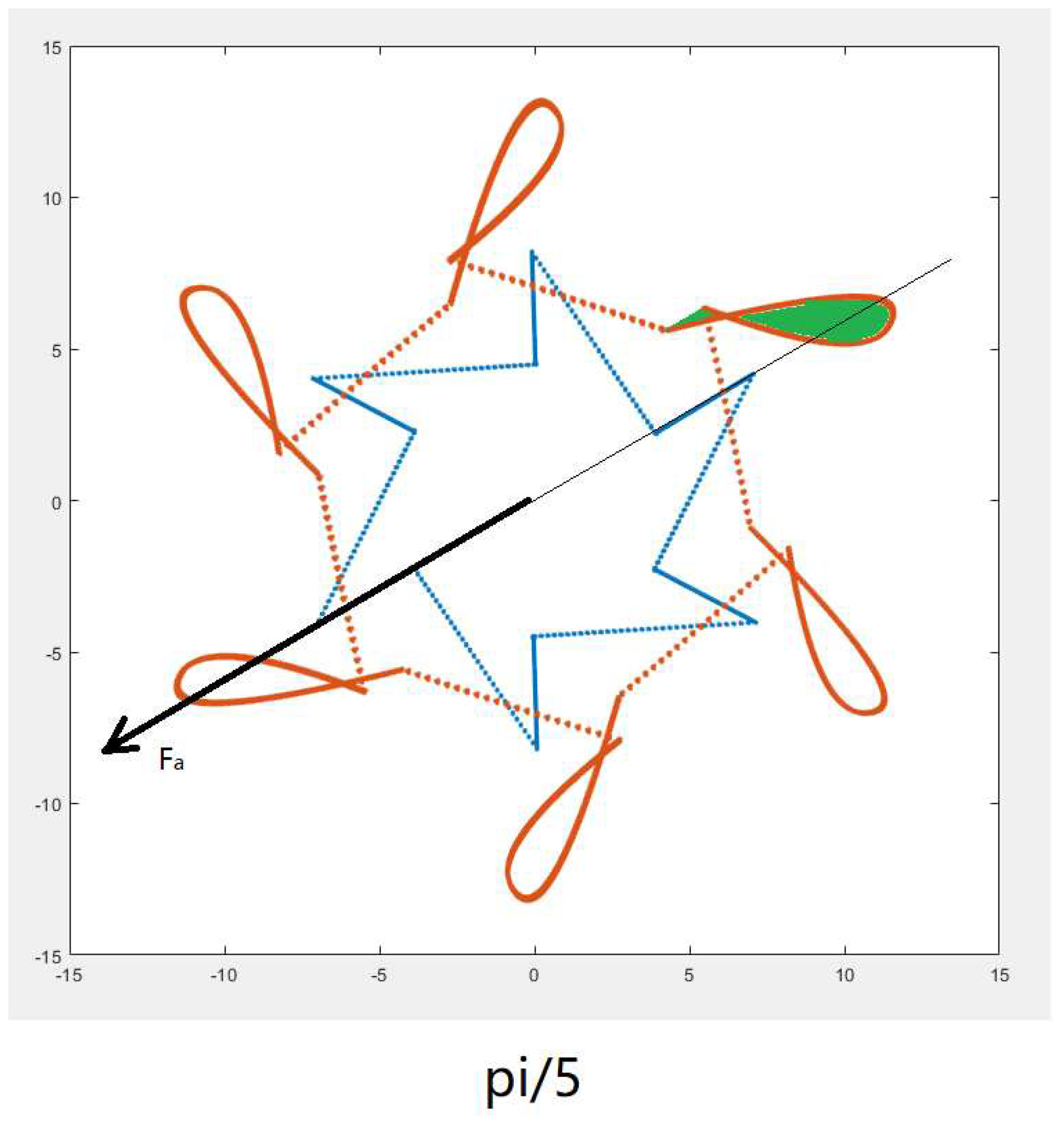
In Figure 11, the dashed line represents the resultant magnetic potential during commutation. Because the simulation step length is less than the commutation time, a dashed line appears multiple times; the solid line is the change of the magnetic potential during a certain phase; the blue solid line is no weak magnetic The magnetic potential trajectory of normal commutation; the brown solid line is the magnetic potential trajectory when the field is weakened; the green indicates that the inverter circulation affects the combined magnetic potential and the area swept by the magnetic potential. The six-angle image of the blue line is the six magnetic potential directions of the 6-step commutation method. The inductance effect of the winding causes the current to gradually increase[21,22], and the magnitude of the magnetic potential increases without changing the direction. Analyzing the green area, it can be concluded that when the field weakening angle is less than pi/6, the magnetic potential moves forward in the direction of motor rotation. The brown curve indicates that as the motor rotor leaves the field weakening zone, the inverter circulating current will gradually decrease and disappear, and the magnetic potential will return to the position without field weakening. With the increase of the weakening angle, the amplitude of the advance movement of the magnetic potential also becomes larger[23,24].
When the field weakening angle is less than pi/6, the resultant magnetic potential moves forward, but does not lead the rotor 180 degrees, so it only strengthens the field weakening effect and does not produce a braking effect. When the field weakening angle is greater than pi/6, the amplitude of the composite magnetic potential moving forward will continue to increase. In Figure 12, the leading excitation angle is pi/5, and the rotor position is marked as the black oblique straight line in the figure. As a result, a small part of the resultant magnetic potential (green area) exceeds the pi angle of the rotor, forming the braking effect of the motor.

6. Conclusions

During the field weakening control of permanent magnet brushless motors, the leading conduction will generate inverter circulating current in the freewheeling diode, power tube, and stator windings. The inverter circulating current affects the direction of the combined magnetic potential and moves the combined magnetic potential in the direction of rotor rotation. When the field weakening angle is 0-pi/6, the inverter current circulating current moves less than pi/6, which plays the role of field weakening and driving effect; when the forward angle is pi/6-pi/3, the inverter current circulating current The movement range exceeds pi/6, which has the effect of field weakening and braking, resulting in the reduction of motor torque and efficiency. Therefore, the range of the field weakening angle of the permanent magnet brushless motor should be between 0-pi/6.

References

  1. Xia Changliang,Fang Hongwei. Permanent-Magnet Brushless DC Motor and Its Control. TRANSACTIONS OF CHINA ELECTROTECHNICAL SOCIETY. 2012, 27-3, pp–25. [Google Scholar]
  2. Fang Hongwei, Xia Changliang, Fang Youtong. Position servo control of brushless DC motor based on the second discrete filter. Proceedings of the CSEE. 2009, 29-3, pp–65. [Google Scholar]
  3. Zhang Fengge, Du Guanghui, et al. Review on development and design of high speed machine. Transactions of China Electrotechnical Society.
  4. Lai, Yen-Shin; Lin, Yong-Kai. A Unified Approach to Zero-Crossing Point Detection of Back EMF for Brushless DC Motor Drives without Current and Hall Sensors. IEEE TRANSACTIONS ON POWER ELECTRONICS. 2011, 26-6, pp–1704. [Google Scholar] [CrossRef]
  5. Liu Weiguo, Li Rong. Research on Weak Magnetic Mechanism of Tombarthite Permanent Magnet Brushless DC Motor. Journal of North western Polytechnical University. 1996, 25-5, pp–662. [Google Scholar]
  6. MATSUI, N; TAKESHITA, T; YASUDA, KA. NEW SENSORLESS DRIVE OF BRUSHLESS DC MOTOR (View record in Inspec). PROCEEDINGS OF THE 1992 INTERNATIONAL CONFERENCE ON INDUSTRIAL ELECTRONICS, CONTROL, INSTRUMENTATION, AND AUTOMATION. 1992, 1-3, pp–430. [Google Scholar] [CrossRef]
  7. TANBo,LIUWei-guo,MARui-qing,ZHAOJu. Study on speed regulation of BLDCM with weak magnetic field. Small&Special Electrical Machines . 2009, 12, pp–15. [Google Scholar]
  8. Li Rong Liu Weiguo Liu Xiangyang Liu Jinglin. Analysis of Flux-Weakening by Eliminating Circulating Current in PM BLDCM. TRANSACTIONS OF CHINA ELECTROTECHNICAL SOCIETY. 2007, 22-9, pp–62. [Google Scholar]
  9. Ha, JI; Ide, K; Sawa, T; et al. Sensorless rotor position estimation of an interior permanent-magnet motor from initial states. IEEE TRANSACTIONS ON INDUSTRY APPLICATIONS. 2003, 39-3, pp–761. [Google Scholar] [CrossRef]
  10. Lee, Kwang-Woon; Kim, Dae-Kyong; Kim, Byung-Taek; et al. A novel starting method of the surface permanent-magnet BLDC motors without position sensor for reciprocating compressor. IEEE TRANSACTIONS ON INDUSTRY APPLICATIONS. 2008, 44-1, pp–85. [Google Scholar] [CrossRef]
  11. Wang, Zihui; Lu, Kaiyuan; Blaabjerg, Frede. A Simple Startup Strategy Based on Current Regulation for Back-EMF-Based Sensorless Control of PMSM. IEEE TRANSACTIONS ON POWER ELECTRONICS. 2012, 27-8, pp–3817. [Google Scholar] [CrossRef]
  12. Lai, Yen-Shin; Lin, Yong-Kai; Chen, Chih-Wei. New Hybrid Pulsewidth Modulation Technique to Reduce Current Distortion and Extend Current Reconstruction Range for a Three-Phase Inverter Using Only DC-link Sensor. IEEE TRANSACTIONS ON POWER ELECTRONICS. 2013, 28-3, pp–1331. [Google Scholar] [CrossRef]
  13. Chun, Tae-Won; Quang-Vinh Tran; Lee, Hong-Hee; et al. Sensorless Control of BLDC Motor Drive for an Automotive Fuel Pump Using a Hysteresis Comparator. IEEE TRANSACTIONS ON POWER ELECTRONICS. 2014, 29-3, pp–1382. [Google Scholar] [CrossRef]
  14. Shao, JW; Nolan, D; Teissier, M; et al. A novel microcontroller-based sensorless brushless DC (BLDC) motor drive for automotive fuel pumps. IEEE TRANSACTIONS ON INDUSTRY APPLICATIONS. 2003, 39-6, pp–1734. [Google Scholar] [CrossRef]
  15. Kang, Y; Lee, SB; Yoo, JA. microcontroller embedded AD converter based low cost sensorless technique for brushless DC motor drives. Conference Record of the 2005 IEEE Industry Applications Conference, . 2005, 1-4, pp–2176. [Google Scholar] [CrossRef]
  16. Lee, Kwang-Woon; Hong, Jongman; Lee, Sang Bin; et al. Quality Assurance Testing for Magnetization Quality Assessment of BLDC Motors Used in Compressors. IEEE TRANSACTIONS ON INDUSTRY APPLICATIONS. 2010, 46-6, pp–2452. [Google Scholar] [CrossRef]
  17. JAHNS, TM. FLUX-WEAKENING REGIME OPERATION OF AN INTERIOR PERMANENT-MAGNET SYNCHRONOUS MOTOR DRIVE. IEEE TRANSACTIONS ON INDUSTRY APPLICATIONS. 1987, 23-4, pp–681. [Google Scholar] [CrossRef]
  18. Dan M Ionel. Finite element analysis of brushless DC motors for flux weakening opreration. IEEE Trans on Magneties. 1996, 32-5, pp–5040. [Google Scholar]
  19. Zhu, ZQ (Zhu, Z. Q.) ; Shen, JX (Shen, J. X.) ; Howe, D (Howe, D.). Flux-weakening characteristics of trapezoidal back-EMF machines in brushless DC and AC modes. CES/IEEE 5th International Power Electronics and Motion Control Conference. [CrossRef]
  20. Krishnan, R. Permanent magnet synchronous and brushless DC motor drives. PERMANENT MAGNET SYN. 2010. [Google Scholar]
  21. Lee, Dong-Myung; Lee, Woo-Cheol. Analysis of Relationship Between Abnormal Current and Position Detection Error in Sensorless Controller for Interior Permanent-Magnet Brushless DC Motors. IEEE TRANSACTIONS ON MAGNETICS . 2008, 44-8, pp–2074. [Google Scholar] [CrossRef]
  22. Guglielmi, Paolo; Pastorelli, Michele; Vagati, Alfredo. Cross-saturation effects in IPM motors and related impact on sensorless control. IEEE TRANSACTIONS ON INDUSTRY APPLICATIONS . 2006, 42-6, pp–1516. [Google Scholar] [CrossRef]
  23. LiJiangyong,LiuGuohai,JiaHongPing. Flux-weakeing control of Permanent Magnet Brushless DC Motor Used in E-bike. journal of Nanjing Unversity of science and Technology(Natural science) . 2009, 33, pp–76. [Google Scholar]
  24. Jinhai Chenbingbing Chacong. Sensorless Brushless DC Motor for Optimization of Weakening Control. Industrial Control Computer. 2011, 24-7, pp–88. [Google Scholar]
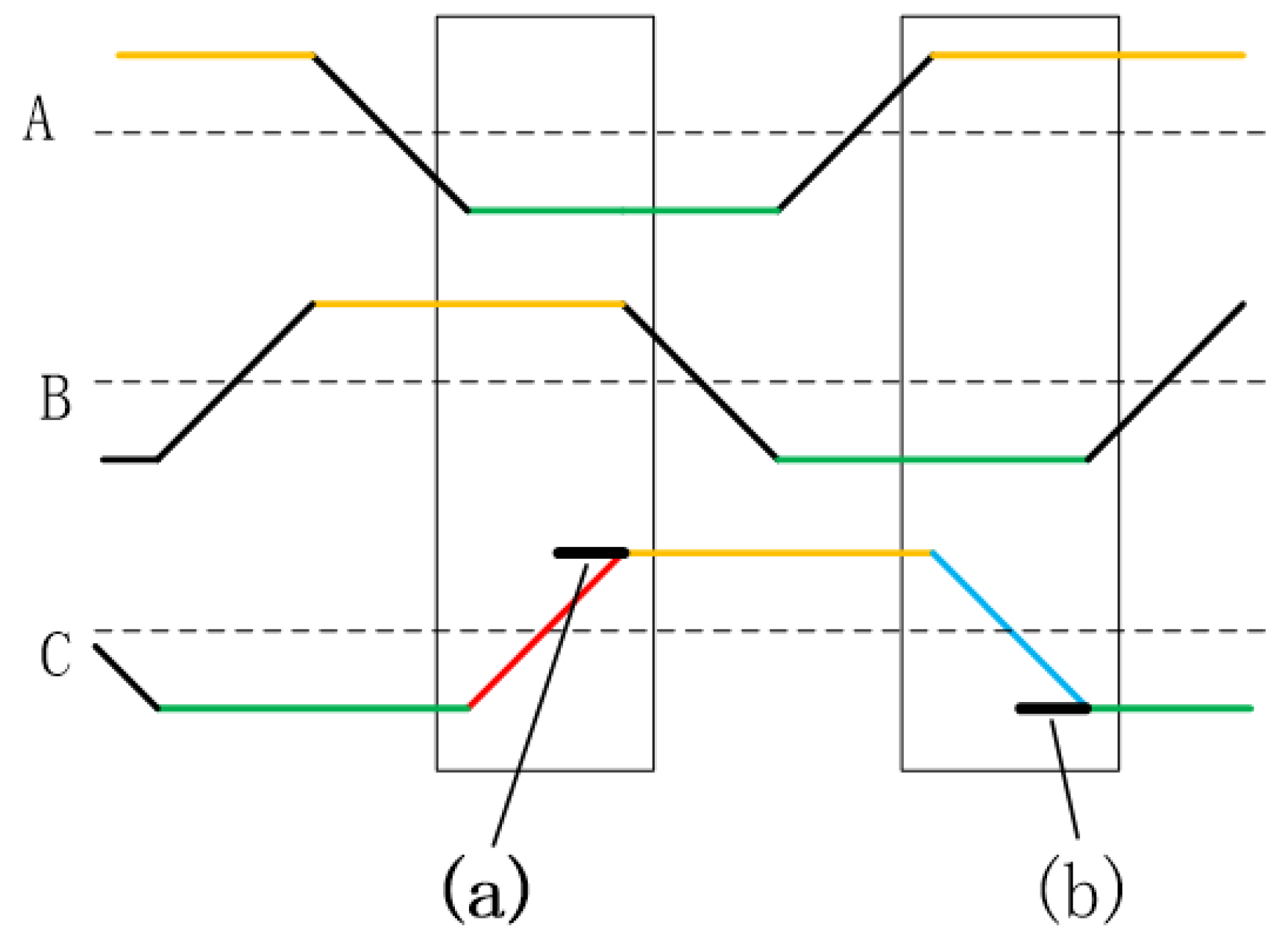
Figure 1. BEMF of BLDC
Preprints 71718 g001
Figure 2. Inverter circulating current of upper and lower arms
Preprints 71718 g002
Figure 3. Decomposition of freewheeling circuit
Preprints 71718 g003
Figure 4. Continuous current of flux-weakening
Preprints 71718 g004
Figure 5. Analysis of magnetic potential generated by inverter circulating current
Preprints 71718 g005
Figure 6. Braking effect of inverter circulating current
Preprints 71718 g006
Figure 7. weak magnetic angle and the Angle between magnetic potential of stator and rotor
Preprints 71718 g007
Figure 8. matlab simulation model
Preprints 71718 g008
Figure 9. The direction of current and magnetic potential of simulation model
Preprints 71718 g009
Figure 10. Change of phase current and weak magnetic potential
Preprints 71718 g010
Figure 11. Magnetic potential distortion caused by inverter circulating current
Preprints 71718 g011
Figure 12. Magnetic potential distortion caused by inverter circulating current
Preprints 71718 g012
Disclaimer/Publisher’s Note: The statements, opinions and data contained in all publications are solely those of the individual author(s) and contributor(s) and not of MDPI and/or the editor(s). MDPI and/or the editor(s) disclaim responsibility for any injury to people or property resulting from any ideas, methods, instructions or products referred to in the content.
Copyright: This open access article is published under a Creative Commons CC BY 4.0 license, which permit the free download, distribution, and reuse, provided that the author and preprint are cited in any reuse.
Prerpints.org logo

Preprints.org is a free preprint server supported by MDPI in Basel, Switzerland.

Subscribe

© 2024 MDPI (Basel, Switzerland) unless otherwise stated