1. Introduction
A laser fusion target may consist of: a solid microsphere for heavy isotopes of hydrogen and a cylinder hohl-raum for laser light conversion into X-rays and energy delivery to the hydrogen-fuel. Additional foam or aerogel layer plays important role in the compression stability control, energy transmission into the solid layers and its transfer. These specific parts and materials are difficult to create and nowhere to borrow from [
1,
2]. The resulting fusion power drastically depends on the accuracy of the target design, fabrication, heating and compression details. Therefore, the proper characterization procedures for development and preparation of the targets are still important and challenging tasks [
3].
X-ray methods have traditionally been used to characterize the target as a whole and to measure a variety of parameters. Among these, projection radiography was an early and still popular option. In this case, the X-rays are coming from a microfocus tube or other point-like source, such as laser driven plasma, Z-pinch, X-pinch, gas-puff, i.e. from fast discharges producing high temperature and dense plasma.
Electro-physical installations on the basis of plasma focus (PF) are among X-ray sources with the highest power and intensity of ionizing emission. They produce routinely neutrons with the energy of 2.5 MeV/14 MeV, X-rays 1-1000 keV, plasma jets, electron- and ion-beams, and electromagnetic pulses. The neutron and X-ray pulse duration lie within tens of nanoseconds [
4,
5].
Using multilayer X-ray mirrors for low-density 10 mg/cc foam characterization is another scheme for transmission imaging with the laser plasma X-ray source made of massive rhenium target irradiated by intense laser beam at a wavelength of 0.53 μm. The plasma X-ray emission was selectively reflected and collimated by Co/C multilayer spherical mirror at a wavelength of 4.5 nm with a polyimide-backed Sc/C filter to produce X-ray images of relatively thick organic samples. The method has been proven to be capable revealing the volume distribution of Cu nanoparticles (10 to 20 wt.%) inside foam materials [
6,
7].
X-ray microtomography with laboratory X-ray sources is known to be both a highly effective and mathematically loaded method as well. It is suitable for the resultant laser target examination and for
in-situ study of the processes and technology routes [
8,
9].
The present work is devoted to synchrotron based X-ray microtomography as one of the most promising method for studying low density materials and microstructures of laser targets. The main object of our investigation was a microstructure to be used as a target in laser fusion experiments. It is a small spherical fuel container embedded in the low-density foam support inside the polymer cylinder. This layout presents a physical model of the laser target inside a hohl-raum.
2. Materials and Methods
2.1 Low-density materials in laser targets
The testing objects of our investigation were several samples of the laser targets containing low density materials. They included a spherical glass micro-container for fusion fuel isotopes of hydrogen, which was fixed inside a hollow plastic cylinder with a low-density three-dimensional network. It should be noted that the target components are rather difficult objects for common X-ray radiography. They differ strongly each from other in size (from millimeter to nanometer) with X-ray density variation by 3 orders of magnitude.
The low-density material trimethylol propane triacrilate (TMPTA) was produced as an aerogel of bulk density 10 mg/cc. This material is a 3D network containing many open pores with the size of about micron. We will further refer to the aerogel as foam, like was commonly done in literature. The method of production of such foam was developed in the Dundee University (UK) and described in [
10].
In laser targets the TMPTA foam can be used to form an ablator on the surface of spherical fuel shell, to study the plasma properties in planar layers, to mitigate plasma instabilities, to suspend the laser target components, to provide laser particle acceleration and so on. In our sample, the foam was used in a compound target to surround and fix a fuel microsphere inside plastic cylinder.
The methods for the placement, alignment, and fixation of a gas-filled microsphere in polymer solution inside the cylinder are described in [
11]. The microsphere position is controlled with the help of micromanipulators and two orthogonal projections observed by microscope. The plastic capillary cylinder is filled with the polymer solution containing the submerged microsphere. When the required alignment and position are achieved, the solution is irradiated by UV laser radiation, which causes polymerization of the solution and fixation of the centered microsphere. The followed non-solvent bath and supercritical drying processes result in a cjmpound laser target consisting of the foam-filled cylinder with the microsphere embedded and centered inside it.
In the present work we selected some irregular samples of such compound laser targets to demonstrate the potential of the synchrotron microtomography as a method to control and monitor this kind of microstructures. The foam and its structural elements (small fiber-like compactions, pores and other inhomogeneity) were observed directly through the relatively dense plastic walls of the cylinder. Thus, our X-ray tomography experiments were aimed at visualization of not only geometry and position of the target parts but also the structure of the very fine foam and at the evenness of the surfaces.
One more object to study was chosen to be CHO-foam loaded with uniformly distributed high-Z element. Such materials are of interest for the laser fusion target production, since heavy chemical elements are known to be efficient converters of laser radiation into X-rays and play an important role in driver energy transfer to the target. Besides that, they determine the stability of the laser plasma processes and total fusion yield of the reaction [
12].
To produce CHO-sample for the synchrotron tomography experiments we followed the procedure described in [
13]: CHO-polymer with 0.05 wt.% of gold atoms in the form of water-solvable salt was subjected to UV photo initiated synthesis, non-solvent bath and supercritical drying. It should be mentioned that common pink color of the produced CHO- foam is inherent to the gold colloid solution.
2.2 Phase contrast X-ray tomography with the synchrotron radiation
To study the laser target internal structure we used a synchrotron radiation beamline with a high quality monochromatic X-ray beam needed for a phase contrast imaging. The experiments were carried out on P14 beamline at synchrotron PETRA III (DESY, Hamburg, Germany) [
14]. The X-ray full photon flux was more than 10
13 photon/s inside a 0.6 x 1.2 mm
2 working region, while the beam transverse coherence was about 500 μm and 20 μm in vertical and horizontal directions, respectively. Earlier this beamline setup was successfully used for various advanced X-ray diffraction experiments, e.g. for studying large (> 100 um) macromolecular crystals [
15].
The samples were mounted on a needle holder and illuminated by an uncorrected X-ray beam. To collect the tomographic data, the holder was fixed on a stage providing an accurate rotation with an error of < 0.001o.
The X-ray images were produced using an optical system consisting of 8-μm thick LSO:Tb scintillator, 20x microscope and 2048x2048 pco.edge 4.2 sCMOS camera (Excelitas PCO GmbH, Kelheim). Given the microscope magnification, the effective pixel size on the object was estimated to be about 0.325 μm over the field of view of about 600 μm.
A typical tomographic scan included a recording of 30 flat-field images and 3600 projections with a step of 0.1
o. The flat-field correction was applied by dividing each projection image by the most similar flat-field image selected according to the SSIM criterion [
16]. To account for possible axis shift at different object-camera distances, the X-ray images were corrected using the Fourier-space correlation with a sub-pixel interpolation [
14].
The phase contrast in X-ray image acquisition was achieved by four-fold repetition of the scan of the same sample at different distances (135-145 cm) from the camera. Then, the sets of recorded X-ray projection images were processed using a method of multi-distance non-iterative holographic reconstruction [
17,
18]. After that, the tomographic reconstruction was performed, as usually, using the TOMOPY package [
19] with application of the Gridrec algorithm and Shepp-Logan filtering.
For better presentation of the reconstructed data in final 3D views we used the following image processing software: Fiji-ImageJ 1.53t (open code) and CTvox v. 3.3.0 r1403 (Bruker MicroCT)]. The Fiji-ImageJ program allowed us to improve brightness/contrast parameters of the reconstructed section images. Finally, the whole stack of the sections was presented as a 3D object with the help of the CTvox program, which enabled highlighting and adjustment of the local intensity and different density. The results of X-ray phase contrast imaging, 3D reconstruction and visualization are given and discussed in
Section 3.
3. Results
3.1. Microsphere in polymer cylinder
The first object under investigation was a low-density structure in laser target suspending a microsphere inside polymer cylinder. The X-ray projections were recorded at the photon energy of 18 keV with the exposure time 10 ms per frame.
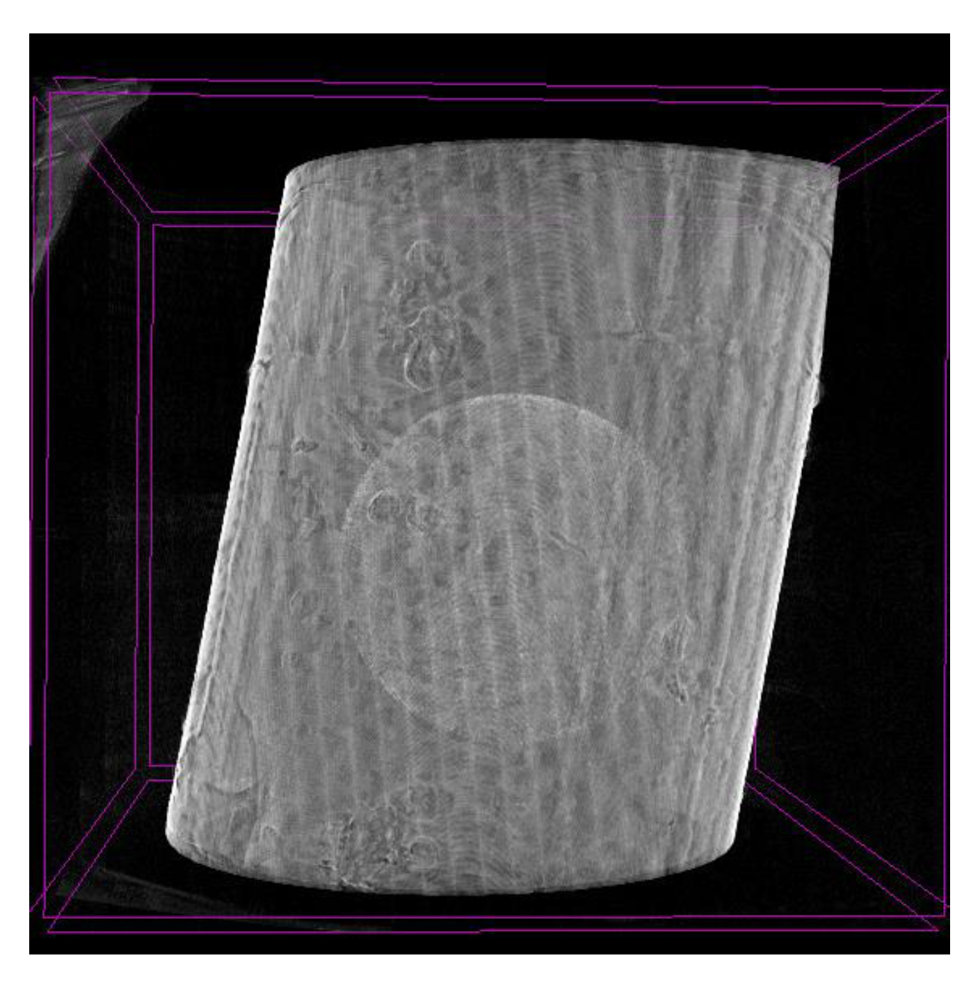
Figure 1 demonstrates the results of the X-ray synchrotron tomography: the reconstructed general view of the foam-filled cylinder with the microsphere centered inside. The main point of attention here is 2 objects: the outer cylinder and the inner fuel-container - microsphere. One can see their mutual symmetrical location; to the right the microsphere’s solid walls have no damages (and hydrogen loss).
Figure 1 shows also the uniformity of the surrounding foam in this delicate structure in the whole volume and in the gap between the sphere and cylinder, with the foam density being much less than that of the glass sphere.
As was mentioned above, in our study we investigated only not-ideal samples of the laser targets, which were not used in laser plasma experiments. On the other hand, a visualization of the micro-structure imperfections is considered to be an evident demonstration of the efficiency of X-ray synchrotron microtomography as a method for such kind of investigations..
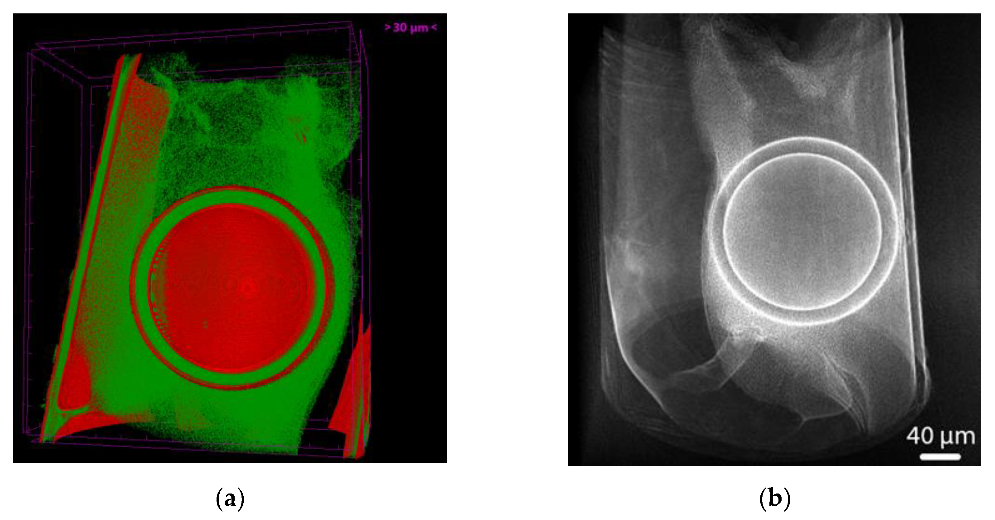
Figure 2 can be regarded as proof that the fuel container is able to withstand the technological procedure of laser target fabrication. This microsphere survived wet processing, numerous handling and mounting steps and the critical point drying. Note that for better presentation of the foam, the cylinder walls were made more transparent.
In
Figure 2a there is less dense substance clearly observable at the top of the picture, while denser one is located below the microsphere and to the right of it. We can see also the perfect sphericity of the fuel microsphere and the equal thickness (15 μm) of its wall. The thickness of the cylinder wall is measured to be 11 μm.
Figure 2b shows the relative position of the microsphere and its decentralization. It should be stressed that X-Ray synchrotron tomography has demonstrated the dynamic range high enough for the simultaneous observation of low-density CHO foam with a density of 10 mg/cc, the inner glass spherical fuel container with a density of 2500 mg/cc, and plastic CH-cylinder with a density of about 1000 mg/cc.
In
Figure 2b one can see that the fuel container position is not ideal. In addition, there are cracks and density uniformities in the foam filled parts of the volume. At the same time, the microsphere itself seems to be viable.
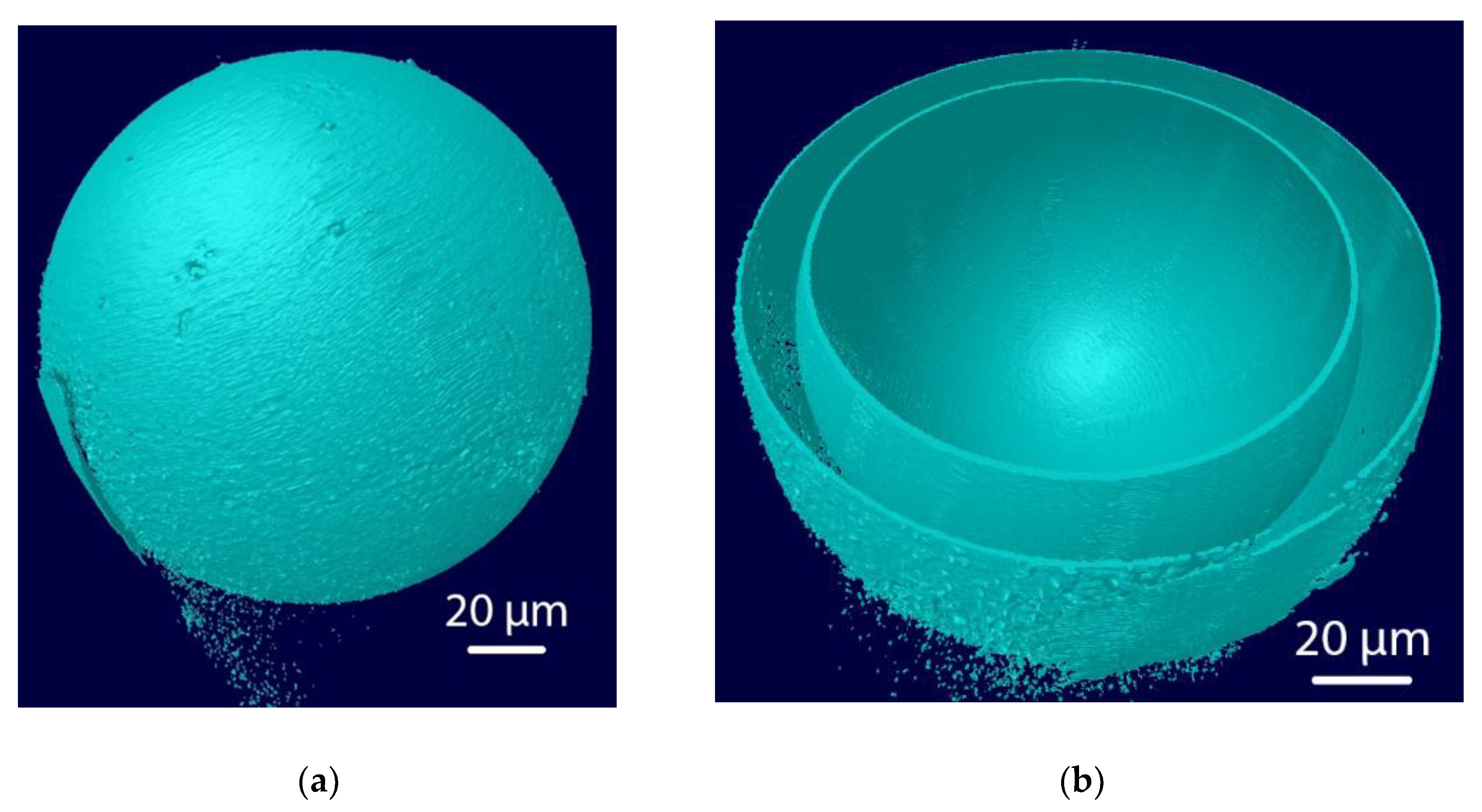
Figure 3 verifies its quality as a possible fuel container. In the lower left part of
Figure 3a a remarkable surface defect is seen, which looks like a crack on the microsphere’s surface. Of course, a through-hole crack is a very serious defect resulting in leaking gas from the fuel container, which makes the container unsuitable. However,
Figure 3b resolves the doubts about the nature of the surface defect shown in
Figure 3a. We see no cracks or holes onto the internal surface. Thus, we can suggest that the object in
Figure 3a seems to be a stick-like piece of another material, e.g. broken glass shell, which got stuck to the external surface of fuel microsphere without any serious damages of the surface.
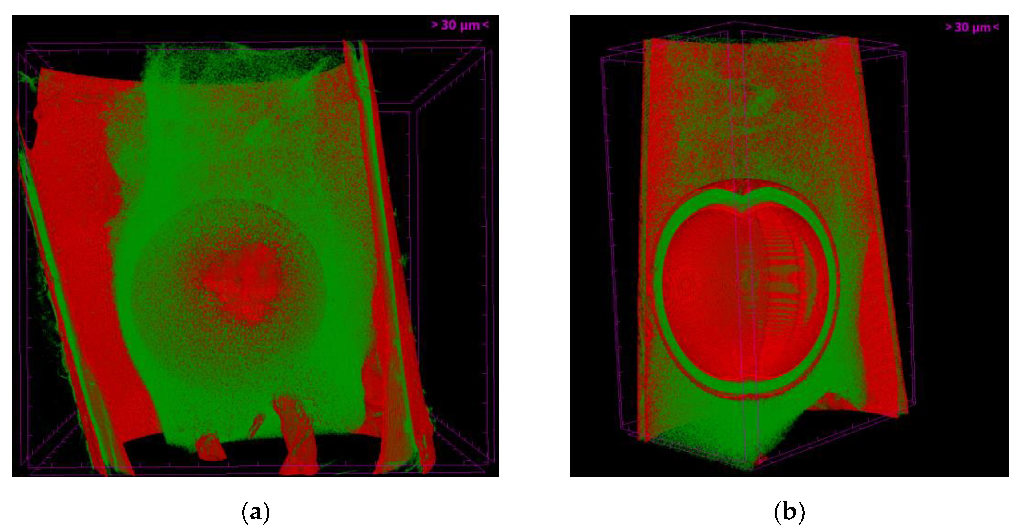
Figure 4a show the sectional views obtained by the crossing plane cut at the position one microsphere radius higher than that in
Figure 2a. The plane above the microsphere and the foam are slightly dimmed to keep the cut-off crossections visible. The foam and microsphere are shown to be displaced in downward direction. Note that the foam is presented here as a partially transparent medium just to depict the inner microsphere.
Unlike
Figure 4a the foam shown in
Figure 4b is cut-off together with the microsphere. As was mentioned above, one can see that optically thinner material at the top part and optically denser one is accumulated at the bottom and to the right of the microsphere. The sphericity on the cross-section of the fuel microsphere with the uniform shell wall thickness of 15 μm is the same in all directions and that fact is exemplified again in this picture.
3.2. CHO foam loaded with high-Z
The second type of the laser target materials was a CHO foam loaded with high-Z The tomographic scans on P14 beamline were carried out at the photon energy 18 keV. Due to extremely low density of foam material in this case the phase contrast enhancement of the X-ray images was critical. The scans were performed at 4 different distances from the camera to provide the necessary datasets for phase retrieval algorithms (see
Section 2): 4.5 cm, 5 cm, 5.6 cm, and 6.5 cm.
There are many reasons to use low-density materials as laser targets. In the recent years one of the popular directions was the application of near-critical aerogels for laser-initiated particle acceleration and electromagnetic fields generation (sometimes called “table-top accelerator”) [
20,
21,
22]. In these applications the essential processes are not so sensitive to the surface – the electron acceleration takes place throughout the volume and must have enough time and path inside the foam to attain the energy by acceleration. So one should carefully study the foam uniformity over the volume by the non-destructive method before the laser experiment. Therefore, we consider the X-ray synchrotron tomography with implementation of phase contrast retrieval as one of the most efficient methods for characterization of the low-density foam materials and corresponding laser targets.
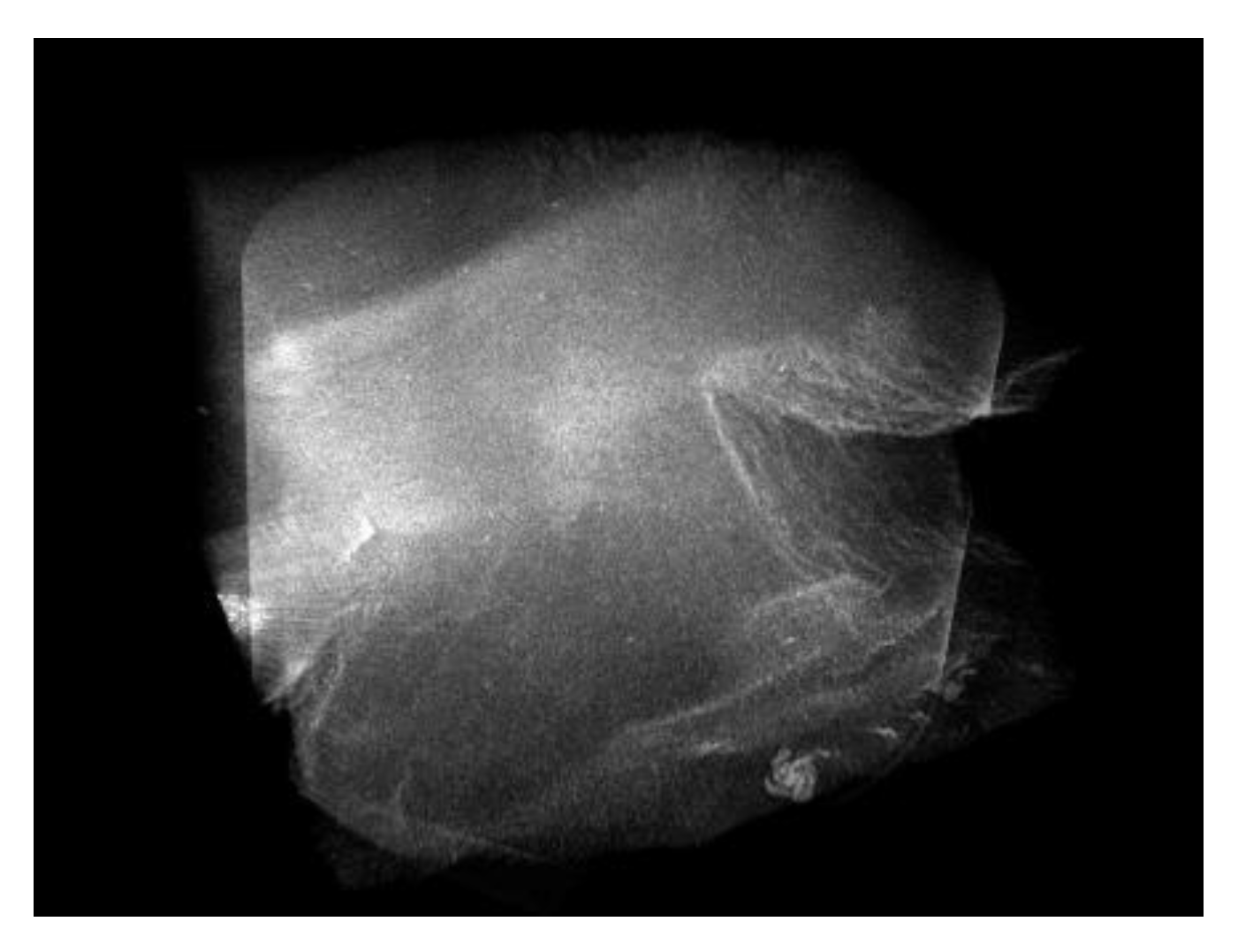
It’s well known that any addition and mixing of metal nanoparticles into the foam volume require proper uniformity as regards to the spatial distribution and the sizes of the particles. Chemical reduction of metallic salts with formation of the colloidal metal nanoparticles is a frequently used method of solid or gel M-loading. (Au in CHO-polymer).
In the sample shown in
Figure 5 the 0.05%-gold admixture is assumed to be spread uniformly over the sample volume. (Gold nanoparticles make the foam to be of delicate pink color). Nevertheless, obtained 3D view (see
Figure 5) shows that along with the regular structure of the 3D polymer network there are defects resulted from the variation of the density due to possible change of the local concentration of the colloidal gold particles. This effect is caused usually by uncontrolled microfluidics in the course of sample fabrication.
It should be mentioned that
Figure 5 is a clear visualization of density variation and uniformity in low density foams which are of special interest for recent research in the field of laser particle acceleration through the long and uniform low-density media [
23,
24].
The plasma experiments consuming the targets we mention here are not limited by this topic. With higher metal concentration the gold is very good converter of laser light to X-rays, which is a valuable feature. The targets and their characterization are equally required in the astrophysics laboratory modeling, non-linear phenomena study, mitigation of plasma instabilities, laser-plasma interaction and others. Synchrotron tomography is extremely useful in this sphere.
4. Discussion
The research of non-fusion target was prepared with the aim of principle studying the possibility of the laser target investigation by means of synchrotron-based X-ray tomography. It consisted of the gas-filled glass micro-balloon for the fuel of heavy hydrogen fixed by the low-density cushion inside the hollow plastic cylinder. . The glass micro balloon of the laser target quality was fabricated as fuel container beforehand at the Lebedev Physical Institute using the original method. [
25]. This target assembly was created to find out firstly the possibility to characterize the low-density material in the form of 3D aerogel network only several-fold denser than an air at normal conditions. Secondly, it was not clear, if the aerogel network with its nanostructure is sufficiently visible and reconstructed inside and over solid parts of the assembly prepared. Thirdly, the question of the total target characterization (in all its constituents at once) should be answered and experimentally proved using the synchrotron tomography.
The studied object contained characteristic details which differed in spatial fragments from millimeter to nanometer scale. In this case, the characteristic densities (mass and optical) varied by at least 3 orders of magnitude within the real object under consideration. And even so, all parts of the object under study were successfully reconstructed. The precise measurement of the complex microstructured assemblies proved possible with this method.
There are many issues where the similar or the same parameter range realizes with poor contrast of the constituents. The possible but not only those tasks could be mentioned: objects for micro-, nano- and spintronics, lithography of different kinds and other high-tech activities. Other fields to apply the similar method and regimes found could be microbiology, medical experiments and natural materials study.
One of the objects studied and described was an assembly of 3 parts “sphere in the foam in the cylinder”. It was not a mechanical assembly, and the 3 parts were not fabricated independently. The microsphere and the cylinder born in a separate technologic processes has been then involved in the several-stage synthesis, treatment, aging and critical point drying techniques to be united in a complete target studied by the microtomography method. This method proved successful and capable of analyzing the materials and quality of all the 3 parts of the target differing strongly from each other. The target assembly is also possible to characterize non-distructively in respect to the geometry, prescribed composition, symmetry of the construction and fitting the necessary design.
Though the method described and proposed was not fully applied to the complex target used for the target reconstruction, the enough parameters have been measured. This is because the simpler target design had been realized. For a fine separate aerogel structure the phase contrast became necessary.
Also there is just no chance to fulfill the total measurement without phase contrast measurements when the inner layer of condensed fuel inside the container appears in the target for the ICF or IFE experiments. Beryllium and other light elements including the hydrogen isotopes needed for the energy effective fusion burn can be measured only with the phase contrast approach. In such targets the hierarchy of scales and densities exists quite similar to the relative parameters from the present study [
26].
Author Contributions
Conceptualization, I.A. and N.B.; methodology, I.A. N.B, M.P. and G.B,; software, M.P. and G.B.; validation, N.B. and A.E.; formal analysis, I..A.; investigation, M.P., G.B., N.B. and I.A.; resources, G.B. and M.P.; data curation, M.P.; writing—original draft preparation, I.A.., M.P., N.B.; writing—review and editing, I.A. and A.V.; visualization, I.A. and A.E.; supervision, A.V.; project administration, I.A..; funding acquisition, I.A., N.B. and A.V. All authors have read and agreed to the published version of the manuscript.
Funding
This research was partly funded by the P.N. Lebedev Physical institute New Scientific Group 55.
Acknowledgments
Support in experimental chemistry by W. Nazarov, sample preparation and treatment by L. Borisenko are gratefully acknowledged.
Conflicts of Interest
The authors declare no conflict of interest.
References
- Merkul'ev, Yu. A. Low-density absorber - converter of laser fusion target with direct laser beams irradiation. In Proceedings of the Russian-China Seminar, 29 March-3 April 1992. [Google Scholar]
- Merkuliev, Yu. A. Low density high-Z layer for indirect target converters. In Proceedings of the China-Russia Seminar, Chengdu, China, May 1993. [Google Scholar]
- Khalenkov, A. M.; Borisenko, N. G.; Kondrashov, V. N.; Merkuliev, Yu. A.; Limpouch, J; Pimenov, V.G. Experience of micro-heterogeneous target fabrication to study energy transport in plasma near critical density. Laser Part. Beams 2006, 24, 283–290. [CrossRef]
- Mikhailov, Yu. V.; Lemeshko, B. D.; Prokuratov, I. A. Experimental dependence of the neutron yield on the discharge current for plasma focus chambers filled with deuterium and deuterium-tritium. Plasma Phys. Rep. 2019, 45, 334–344. [Google Scholar] [CrossRef]
- Avraham, E. B.; Porath, Y. The use of a dense plasma focus accelerator in nuclear physics. Nucl. Instrum. Methods 1975, 123, 5–9. [Google Scholar] [CrossRef]
- Artyukov, I. A.; Borisenko, N. G.; Kasyanov, Y. S.; Khalenkov, A. M.; Pimenov, V. G.; Vinogradov, A. V. Fabrication and characterization of low-density polymer laser targets both with or without high-Z dopants. In Proceedings of the 29th European Conference on Laser Interaction with Matter (ECLIM), Madrid, Spain, June 2006. [Google Scholar]
- Artyukov, I.; Feschenko, R.; Vinogradov, A.; Bugayev, Y.A.; Devizenko, O.; Kondratenko, V.; Kasyanov, Y.S.; Hatano, T.; Yamamoto, M.; Saveliev, S. Soft X-ray imaging of thick carbon-based materials using the normal incidence multilayer optics. Micron 2010, 41, 722–728. [Google Scholar] [CrossRef]
- Borisenko, N. G.; Akunets, A. A.; Artyukov, I. A.; Gorodnichev, K. E.; Merkuliev, Yu. A. X-ray tomography of the growing silica gel with a density gradient. Fusion Sci. Technol. 2009, 55, 477–483. [Google Scholar] [CrossRef]
- Montgomery, D.S. Invited article: X-ray phase contrast imaging in inertial confinement fusion and high energy density research. Rev. Sci. Instrum. 2023, 94, 021103. [Google Scholar] [CrossRef]
- Falconer, J.W.; Golnazarians, W.; Baker, M.J.; Sutton, D.W. Fabrication of cylindrical, microcellular foam-filled targets for laser-driven experiments. Vac. Sci. Technol. A 1990, 8, 968–971. [Google Scholar] [CrossRef]
- Horsfield, C.J.; Nazarov, W.; Oades, K. In-situ polymerization of foam filled laser targets with two regions of different densities, separated by a thin film. Fus. technol. 1999, 35, 95–100. [Google Scholar] [CrossRef]
- Gromov, A.I.; Borisenko, N.G.; Gus'Kov, S.Y.; Merkul'ev, Y.A.; Mitrofanov, A.V. Fabrication and monitoring of advanced low-density media for ICF targets. Laser Part. Beams 1999, 17, 661–670. [Google Scholar] [CrossRef]
- Borisenko, N.G.; Gromov, A.I.; Merkulev, Y.A.; Mitrofanov, A.V.; Nazarov, W. Regular foams, loaded foams and capsule suspension in the foam for hohlraums in ICF. Fus.technol. 2000, 38, 115–118. [Google Scholar] [CrossRef]
- Polikarpov, M.; Bourenkov, G.; Snigireva, I.; Snigirev, A.; Zimmermann, S.; Csanko, K.; Brockhauser, S.; Schneider, T.R. Visualization of protein crystals by high-energy phase-contrast X-ray imaging. Acta Crystallogr. D 2019, 75, 947–958. [Google Scholar] [CrossRef]
- Santos, K.F.; Jovin, S.M.; Weber, G.; Pena, V.; Lührmann, R.; Wahl, M.C. Structural basis for functional cooperation between tandem helicase cassettes in Brr2-mediated remodeling of the spliceosome. PNAS 2012, 109, 17418–17423. [Google Scholar] [CrossRef]
- Wang, Z. .; Bovik, A.C.; Sheikh, H.R.; Simoncelli, E.P. Image quality assessment: from error visibility to structural similarity. IEEE Trans. Image Process. 2004, 13, 600–612. [Google Scholar] [CrossRef]
- Cloetens, P.; Ludwig, W.; Baruchel, J.; Van Dyck, D.; Van Landuyt, J.; Guigay, J.P.; Schlenker, M. Holotomography: Quantitative phase tomography with micrometer resolution using hard synchrotron radiation x rays. Appl. Phys. Lett. 1999, 75, 2912–291. [Google Scholar] [CrossRef]
- Zabler, S.; Cloetens, P.; Guigay, J.P.; Baruchel, J.; Schlenker, M. Optimization of phase contrast imaging using hard x rays. Rev. Sci. Instrum. 2005, 76, 073705. [Google Scholar] [CrossRef]
- Gursoy, D.; De Carlo, F.; Xiao, X.; Jacobsen, C. TomoPy: a framework for the analysis of synchrotron tomographic data. J. Synchrotron Rad. 2014, 21, 1188–1193. [Google Scholar] [CrossRef] [PubMed]
- Borisenko, L.A.; Borisenko, N..G.; Mikhailov, Y.A.; Orekhov, A.S.; Sklizkov, G.V.; Chekmarev, A.M.; Shapkin, A.A. Time evolution of the distribution function for stochastically heated relativistic electrons in a laser field of picosecond duration. Quant. Electronics 2017, 47, 915–921. [CrossRef]
- Rosmej, O.N.; Andreev, N.E.; Zaehter, S.; Zahn, N.; Christ, P.; Borm, B.; Radon, T.; Sokolov, A.; Pugachev, L.P.; Khaghani, D.; et al. Interaction of relativistically intense laser pulses with long-scale near critical plasmas for optimization of laser based sources of MeV electrons and gamma-rays. New J. Phys. 2019, 21, 043044. [Google Scholar] [CrossRef]
- Rosmej, O.N.; Gyrdymov, M.; Günther, M.M.; Andreev, N.E.; Tavana, P.; Neumayer, P.; Zähter, S.; Zahn, N.; Popov, V.S.; Borisenko, N.G.; et al. High-current laser-driven beams of relativistic electrons for high energy density research. Plasma Phys. Control. Fusion 2020, 62, 115024. [Google Scholar] [CrossRef]
- Günther, M.M.; Rosmej, O.N.; Tavana, P.; Gyrdymov, M.; Skobliakov, A.; Kantsyrev, A.; Zähter, S.; Borisenko, N.G.; Pukhov, A.; Andreev, N.E. Forward-looking insights in laser-generated ultra-intense γ-ray and neutron sources for nuclear application and science. Nat. Commun. 2022, 13, 170. [Google Scholar] [CrossRef]
- Borisenko, N.G.; Akunets, A.A.; Borisenko, L.A.; Gromov, A.I.; Orekhov, A.S.; Pastukhov, A.V.; Pimenov, V.G.; Tolokonnikov, S.M.; Sklizkov, G.V. “Noizy” low-density targets that worked as bright emitters under laser illumination. J. Phys.: Conf. Ser. 2020, 1692, 012026. [Google Scholar] [CrossRef]
- Borisenko, N. G.; and A. Mercul'ev, Yu. Laser Thermonuclear Targets and Superdurable Microballoons, Isakov, A.I., Ed.; Nova Science Publishers: USA, 1996. [Google Scholar]
- Borisenko, N.G.; Dorogotovtsev, V.M.; Gromov, A.I.; Guskov, S.Y.; Merkul’ev, Y.A.; Markushkin, Y.E.; Chirin, N.A.; Shikov, A.K.; Petrunin, V.F. Laser Targets of Beryllium Deuteride. Fus. Technol. 2000, 38, 161–165. [Google Scholar] [CrossRef]
|
Disclaimer/Publisher’s Note: The statements, opinions and data contained in all publications are solely those of the individual author(s) and contributor(s) and not of MDPI and/or the editor(s). MDPI and/or the editor(s) disclaim responsibility for any injury to people or property resulting from any ideas, methods, instructions or products referred to in the content. |
© 2023 by the authors. Licensee MDPI, Basel, Switzerland. This article is an open access article distributed under the terms and conditions of the Creative Commons Attribution (CC BY) license (http://creativecommons.org/licenses/by/4.0/).
