1. Introduction
In recent years, flapping wing organisms, such as insects and birds, have become the focal point of Bionics due to their unique flight mode, maneuverability, and small scale. Through the use of unsteady aerodynamic mechanisms, insects are able to carry several times their weight during flight [
1,
2]. However, the manufacturing of a real insect remains a significant challenge due to limitations in size and mass. Currently, Flapping Wing Micro-Air Vehicles (FWMAVs) below a few milligrams can only take off against gravity, carry micro sensors, or fly with the assistance of special power supplies [
3], but the duration is very short [
4]; Although FWMAVs below dozens of grams have achieved stable and continuous flight, control strategy, and airborne power supply [
5,
6]. Their added functions significantly exceed those of real insects in terms of mass and dimension. Researchers are continually exploring new driving and design methods for small micro-air vehicles, such as the use of soft artificial muscles [
7]; direct-driven actuation [
8], and multi-wing schemes [
9,
10]. For larger flapping robots, researchers are exploring functions such as imitating insect escape and wing folding behavior [
5]. [
11] The goal is to create insect-like aerial vehicles that are lighter, smaller, and more functional. Several prototypes have been proposed for FWMAVs weighing between 1-10 g, in [
12] a 3.02 g FWMAV was designed with a motor as the driving source and a tail for steering; In [
13], a 3.22 g aerial vehicle with a tail mechanism was proposed, it is a successful attempt in structural design which capable of both flight (flapping and gliding); In [
14], a wireless radiofrequency-powered aerial vehicle weighing 1.8 g and using a piezoelectric drive mode was developed. However, the power supply mode limited the vehicle's ability to achieve further flight. In this paper, we propose a new design method for micro-air vehicles weighing less than ten grams. The robot is driven by two DC motors, with each motor driving a pair of wings. The use of flexure hinges in the transmission design reduces the overall weight of the robot to less than 10 g while also decreasing its volume and mass. This design achieves a more compact size without sacrificing function or performance.
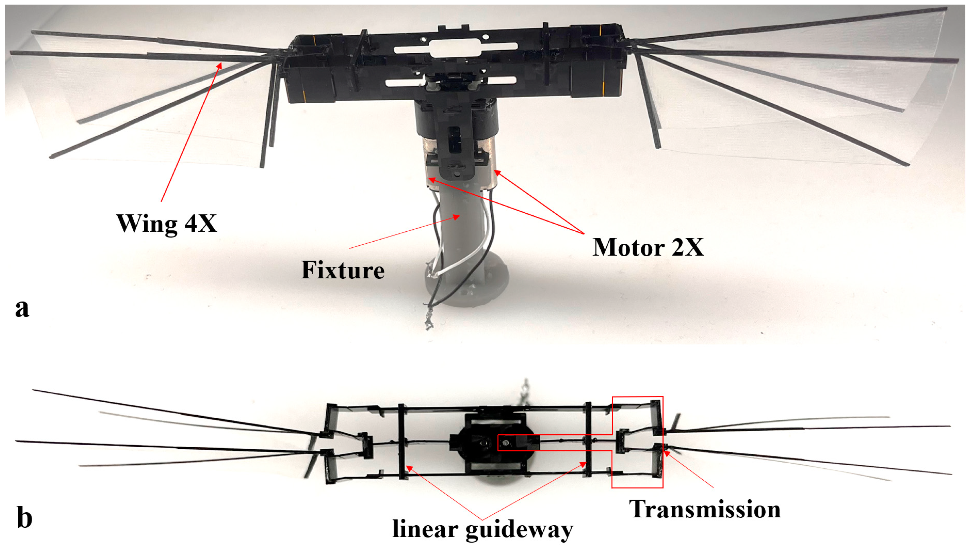
Most insects have two pairs of wings, Diptera (mosquitoes, flies) have only one pair of wings, and the other pair of wings degenerates into a balance bar. We believe that the design of four wings can improve the performance of air robot. We first proposed a new four-wing air vehicle scheme, as shown in
Figure 1. The following work will discuss the design, manufacturing process, and testing of the robot. Finally, we also discussed the significance and limitations of this work.
2. Design of the robot
In recent years, there have been successful demonstrations of flapping wing micro-air vehicles that mimic the flight of insects or small birds, with wingspans ranging from 3 cm [
15,
16] to 33 cm [
5,
17] and weights ranging from 60 mg to 28.2 g. These vehicles are capable of autonomous flight with onboard sensors as their weight increases.
In this study, we present a design and manufacturing scheme for a tailless flapping wing micro-air vehicle that weighs approximately 6 g and has a wingspan of less than 17 cm. The robot features two motors, each of which drives a pair of wings through flexure hinges, enabling the
clap-and-fling phenomenon. Due to the small size of the robot, the design must be simple to achieve a successful prototype. We opted for a reduction motor that does not require a reduction mechanism. The rotary motion is converted into linear motion by a crank-slider mechanism, and the output linear motion is then transformed into flapping wing motion by a slider rocker mechanism. Three hinges which form a four-bar linkage are required to convert linear motion into reciprocating motion, and we utilized Smart Composite Microstructures (SCM) [
18] to achieve three flexure hinges that ensure consistency in movement. The robot consists of several components, including a motor, airframe and transmission, wings, and other connecting parts.
Table 1 shows the mass distribution of these components. The two motors account for 81% of the total weight of the robot. We assembled the reduction motor by connecting a coreless motor and a planetary reducer with a carbon fiber-reinforced pipe that has an inner diameter of 6 mm. The coreless motor weighs approximately 1.6 g, the carbon fiber-reinforced pipe weighs about 0.6 g, and the planetary reducer weighs approximately 0.3 g. Glue is used as a seal at both ends of the carbon fiber-reinforced pipe. The wings are fixed to the transmission with cyanoacrylic glue. Overall, our design and manufacturing scheme for the tailless flapping wing micro-air vehicle utilizes a simple and effective approach that enables the vehicle in an insect scale.
2.1. Body and Transmission
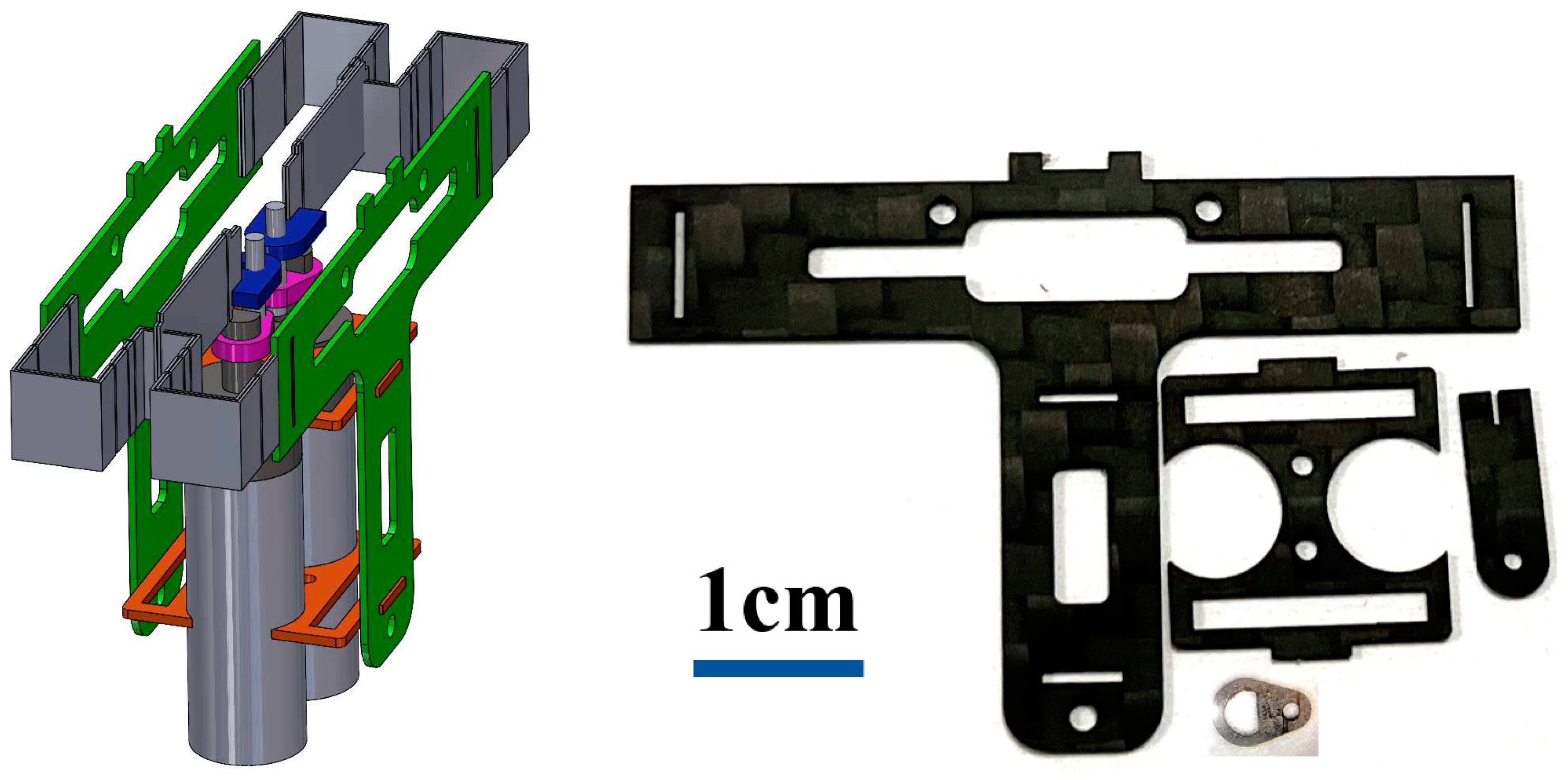
The body is used to install the motor and transmission, which was made of 0.8 mm thick carbon-fiber-reinforced polymer (CFRP), the parts of the body are shown in
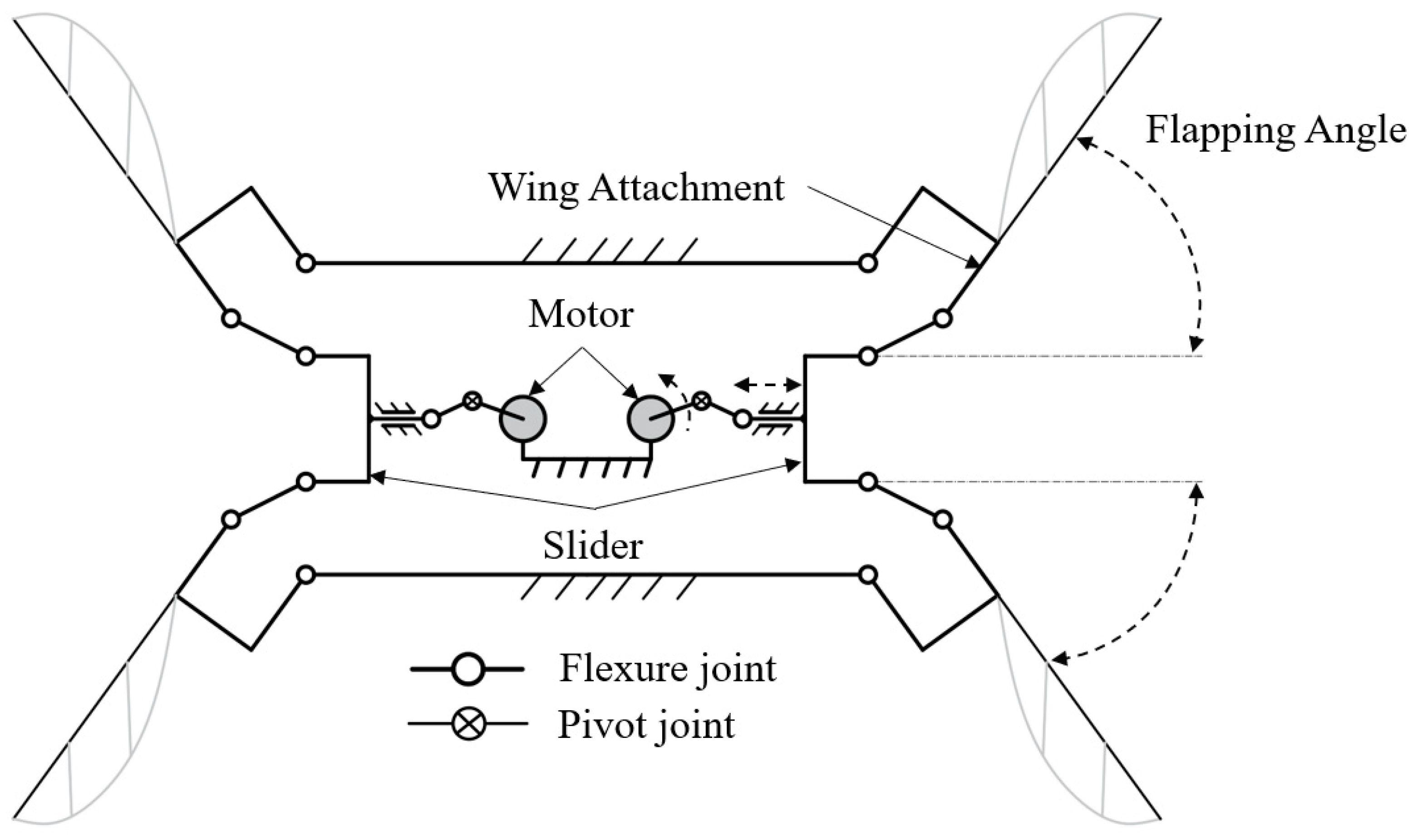
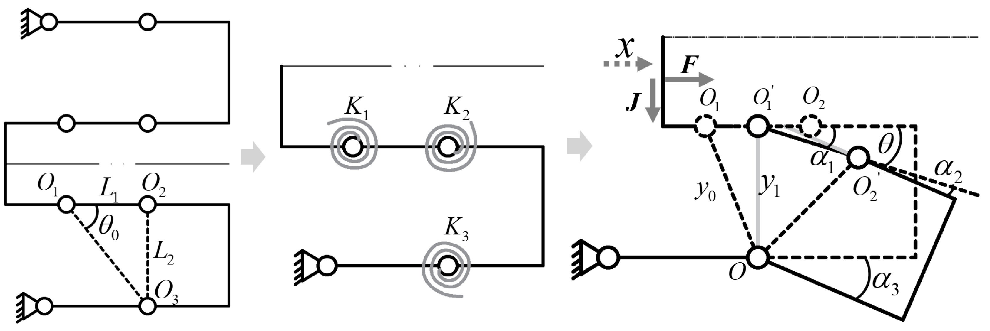
Figure 2. The transmission adopts an integrated design, including two layers of CFRP, two layers of acrylic adhesive (FR1500 Pyralux), and one layer of Polyimide film (PI), and is manufactured by ultraviolet laser. The body and transmission are arranged symmetrically, and the transmission mechanism of the slider rocker is made of 150 microns CFRP and 48 microns PI, the movement principle of the transmission mechanism is shown in
Figure 3. The movement stroke of the slider is 4 mm. When the slider moves to the left, the two wings move to the parallel position; when the slider moves to the right, the two wings open.
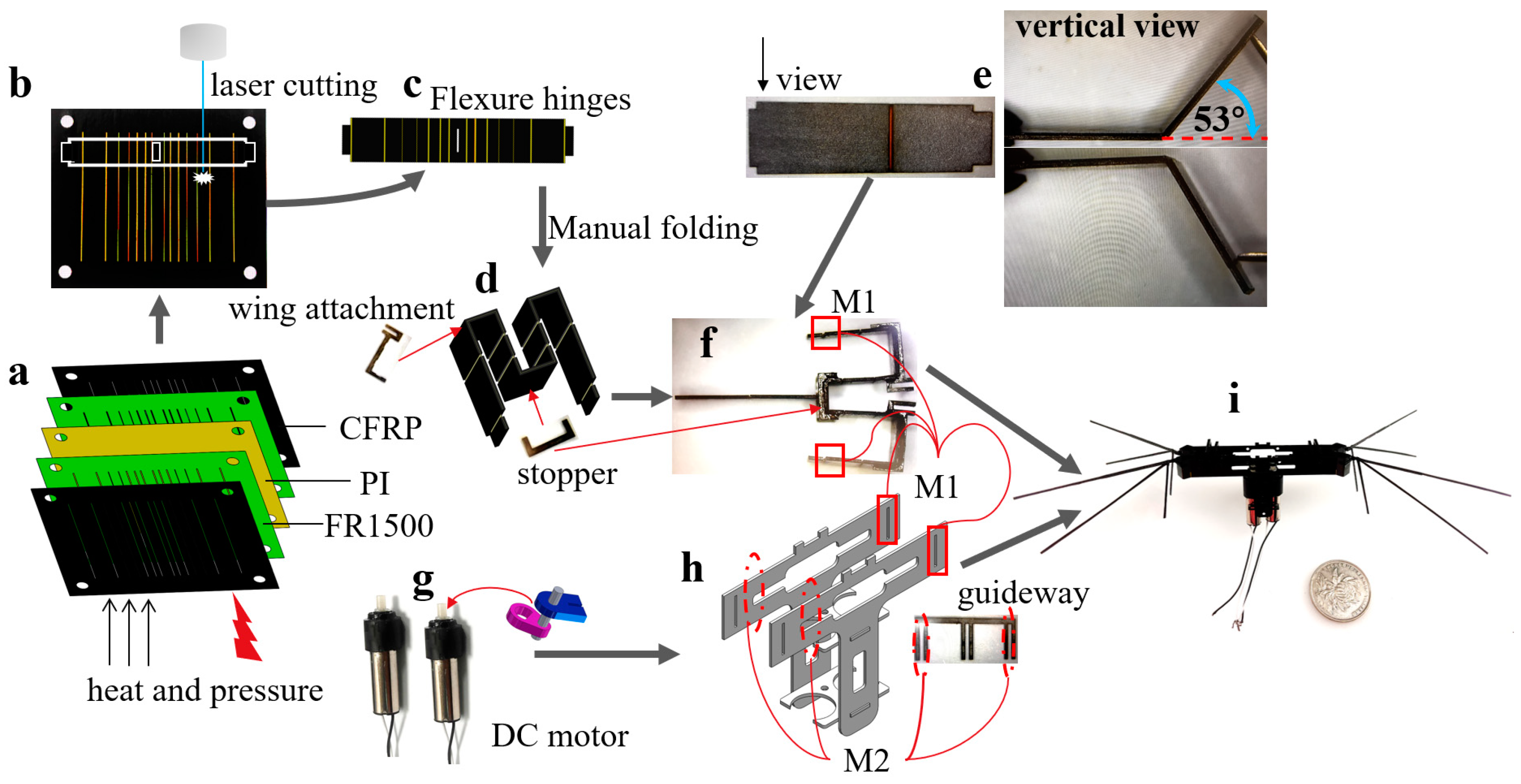
Regarding the design and processing of the transmission, the CFRP is initially processed into the desired contour using ultraviolet laser technology. Similarly, the PI film is processed in the same way. Next, the processed PI film is laminated according to the following sequence: carbon fiber, PI film, and CFRP, adhering to the pin. Under a pressure of 100 kPa and a temperature of 200 °C, these three layers of material are cured for two hours, resulting in a firm composite structure. After secondary processing, the cured composite material is released, and the plane structure is manually folded into a space structure, the machining process of the transmission is shown in
Figure 8.
Figure 2.
The parts of the body, with the three-dimensional diagram on the left indicating the relative position relationship of the parts in the body (with colored). and the physical object of the body parts on the right with a thickness of 0.5mm, processed using an ultraviolet laser.
Figure 2.
The parts of the body, with the three-dimensional diagram on the left indicating the relative position relationship of the parts in the body (with colored). and the physical object of the body parts on the right with a thickness of 0.5mm, processed using an ultraviolet laser.
Figure 3.
Crank-slider/slider-crank transmission.
Figure 3.
Crank-slider/slider-crank transmission.
2.2. Wings
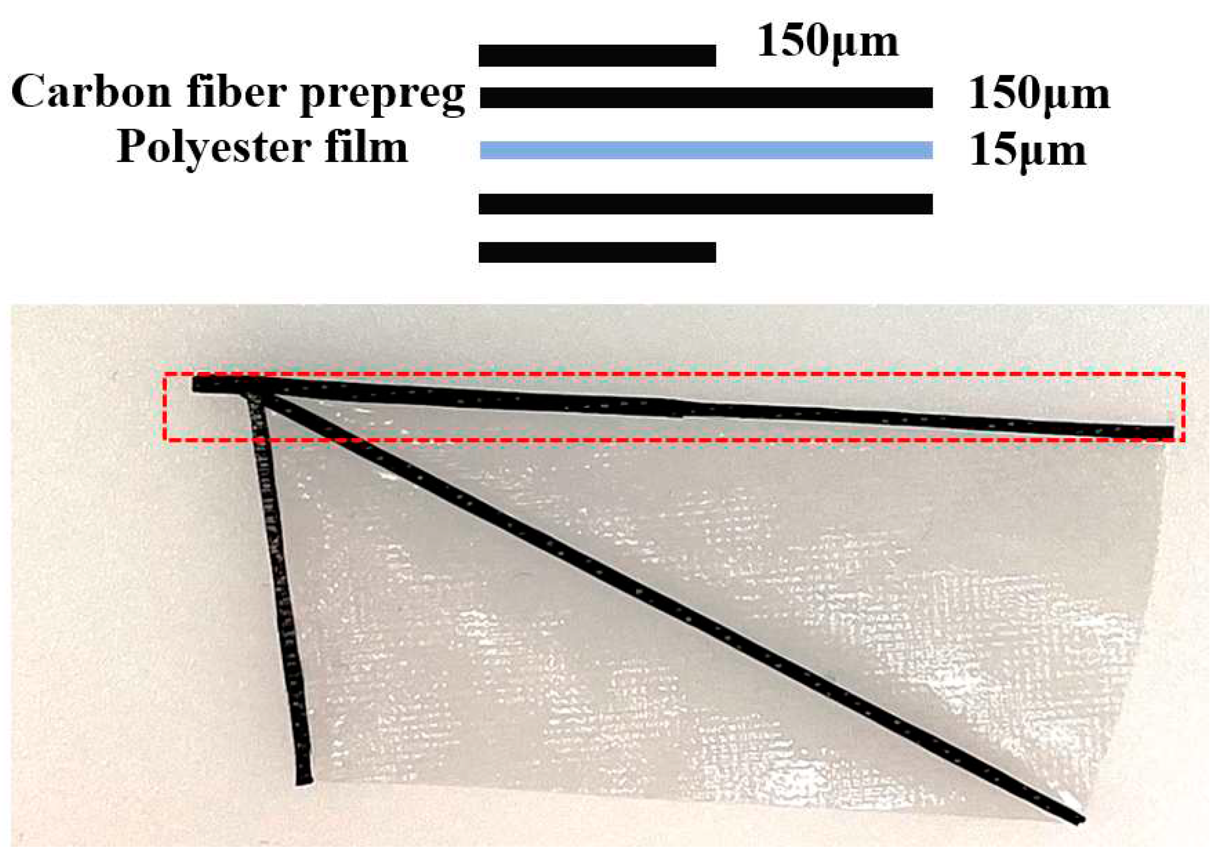
The wings do not use passive twisting for movement, but it does not mean that they do not have passive twisting. Because of inertia, the wings undergo slight passive twisting through deformation during high-frequency motion. The wing consists of two layers of 150 um Carbon fiber prepreg and 12.5 um thick Polyester film. As carbon fiber is an anisotropic material, we ensure that the direction of the wing vein is consistent with that of the carbon fiber. The fixed carbon fiber and PI film are cured at 120 °C, 100 kPa pressure for two hours. The leading edge of the wings is laminated with two layers of carbon fiber prepreg to ensure the stiffness of the leading edge. At the same time, the outermost layer uses half the length of the leading edge to ensure the strength of the wings and reduce their inertia.
Figure 4.
The upper half represents the thickness of each layer of material at the leading edge of the wing, while the lower half represents the actual wing. The wings' branches are made of two layers of 150-micron carbon fiber prepreg.
Figure 4.
The upper half represents the thickness of each layer of material at the leading edge of the wing, while the lower half represents the actual wing. The wings' branches are made of two layers of 150-micron carbon fiber prepreg.
The final weight of the wing was 34.6 mg, with a leading edge length of 55 mm and an area of 1121 mm2. The aspect ratio of a single wing was 2.7.
3. Kinematic analysis
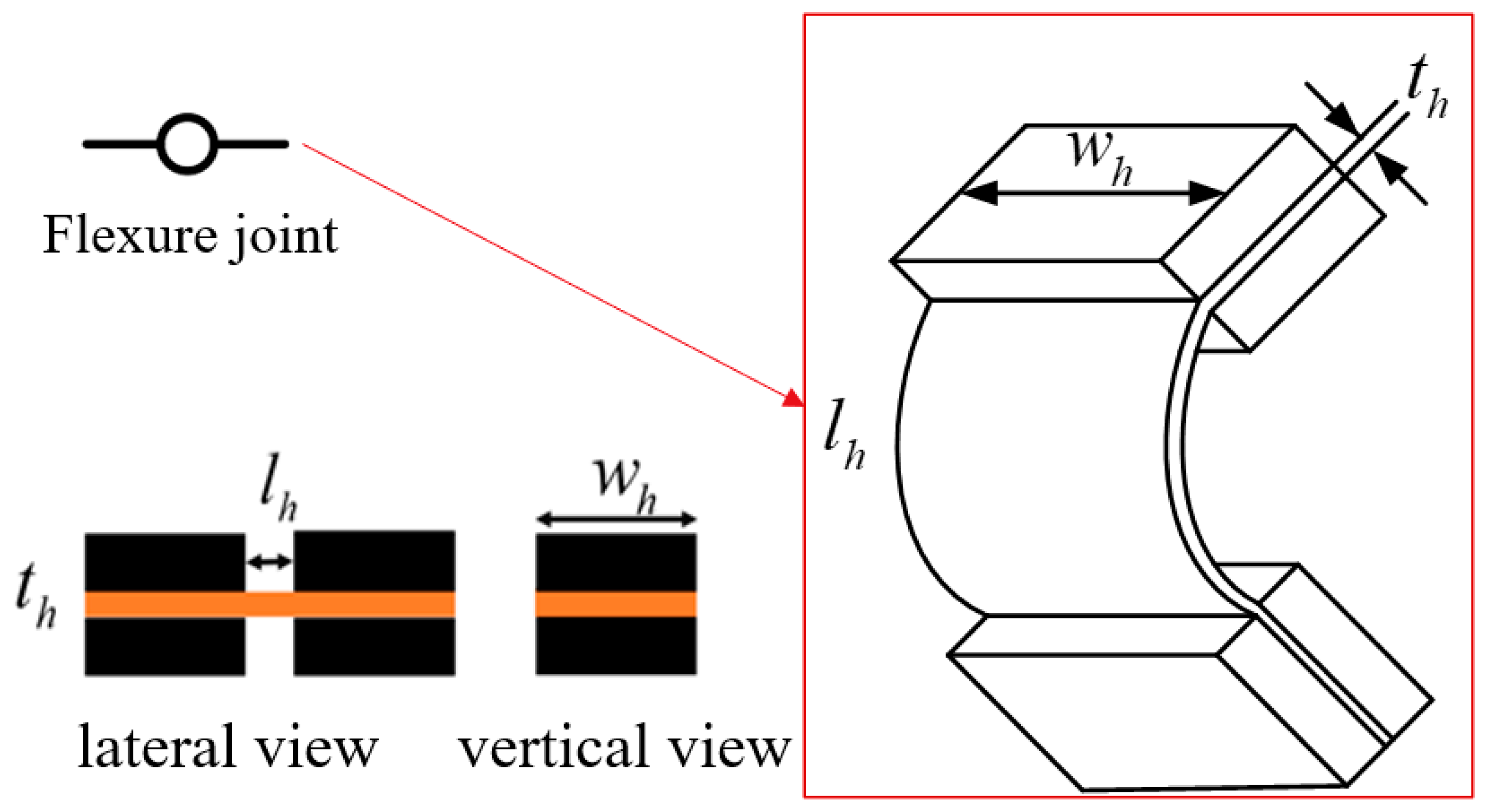
To simplify the analysis, we focus on the right half of the symmetrical robot design. The lower right section, which is also symmetrical in the up-and-down direction, is selected for analysis. However, the 48-microns thickness of the PI film in the middle of the three flexure hinges cannot be ignored, as it affects the output characteristics of the entire system. The physical meaning of the three-dimensional structure and symbol representation of flexure hinge is shown in
Figure 5. we use K1, K2, and K3 to represent their stiffness, as shown in
Figure 6.
The stiffness of the flexure hinges
(i = 1, 2, 3) can be determined by analyzing the material mechanics. When external torque is applied, the free end of the flexure hinge produces a rotation angle, which is calculated using the following equation
where
,
and are the geometric dimensions of the flexure hinge,
is Young's modulus of the PI.
The physical parameters, symbols, and values of the flexure hinge are shown in
Table 2.
When the robot is stationary, the distance between hinge
O1 and
O3 is
y0, the distance between hinge
O1 and
O2 is
L1, and the distance between hinge
O2 and
O3 is
L2. When the slider moves distance
x, the distance between hinge
O1 and
O3 will become
y1, and the equation of
y1 is as follows:
Figure 4 illustrates the meaning and representation of the variables
,
and
, which satisfy the following equation:
By solving Equation (4), we can determine that the rotation angle of each flexure hinge is solely dependent on the displacement of the slider. Additionally, we can derive the force of the flexure hinge when the slider is at a given position, as shown in the following equation:
The equation of wing flapping angle is as follows:
Finally, the equation for the load acting on the slider is given by:
Figure 7.
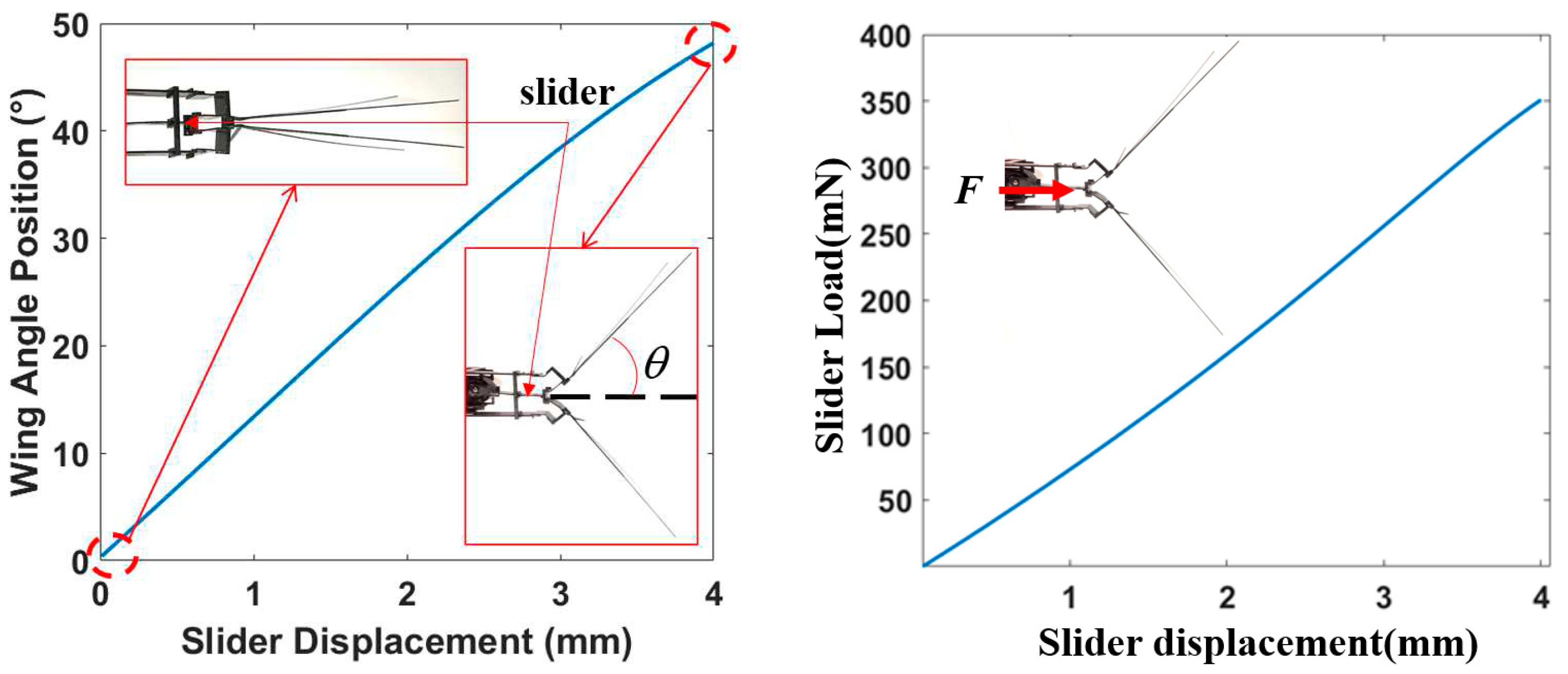
The graph on the left represents wing angular position as a function of slider displacement of the transmission, the dashed circle represents the flapping angle of the wings when the slider reaches its limit position. The graph on the right represents static force as a function of slider displacement.
As depicted in the figure, the maximum flapping angle of a single wing is 48 degrees, while the maximum static load for a slider driving a single wing is 351 mN. Notably, since the slider is linked to a pair of wings on one side of the robot, the maximum static load on a single side is 702 mN. The static load shows an increasing and decreasing trend with the slider's depression due to the kinematic characteristics of the linkage.
4. Assembly and test
The motor is the heaviest component of the robot and its position determines the center of gravity of the entire machine. To achieve a symmetrical design, the motor is installed at the center of gravity of the entire machine, coinciding with the pressure center. The connection between the wings and transmission is secured with glue.
Figure 5 illustrates the assembly of the robot, where the transmission mechanism comprises five layers of materials processed by laser into a rectangular shape, manually folded into a transmission mechanism, and finally installed and fixed through the positioning hole on the frame.
The coreless motor outputs speeds between 2000 and 20000 rpm, which exceed the motion frequency of the wing, making it unsuitable for direct connection to the wing. Therefore, a set of gear reducers is typically required before integrating the motor into the robot design. However, a large gear reducer increases the weight of the robot, reducing its effective load, and makes the robot larger than real insects. To address these issues, a single planet gear reducer weighing only 0.3 grams, which can achieve a reduction ratio of 5.13, is used instead. The coreless motor and planet gear reducers are firmly assembled into a reduction motor using a hollow carbon fiber pipe.
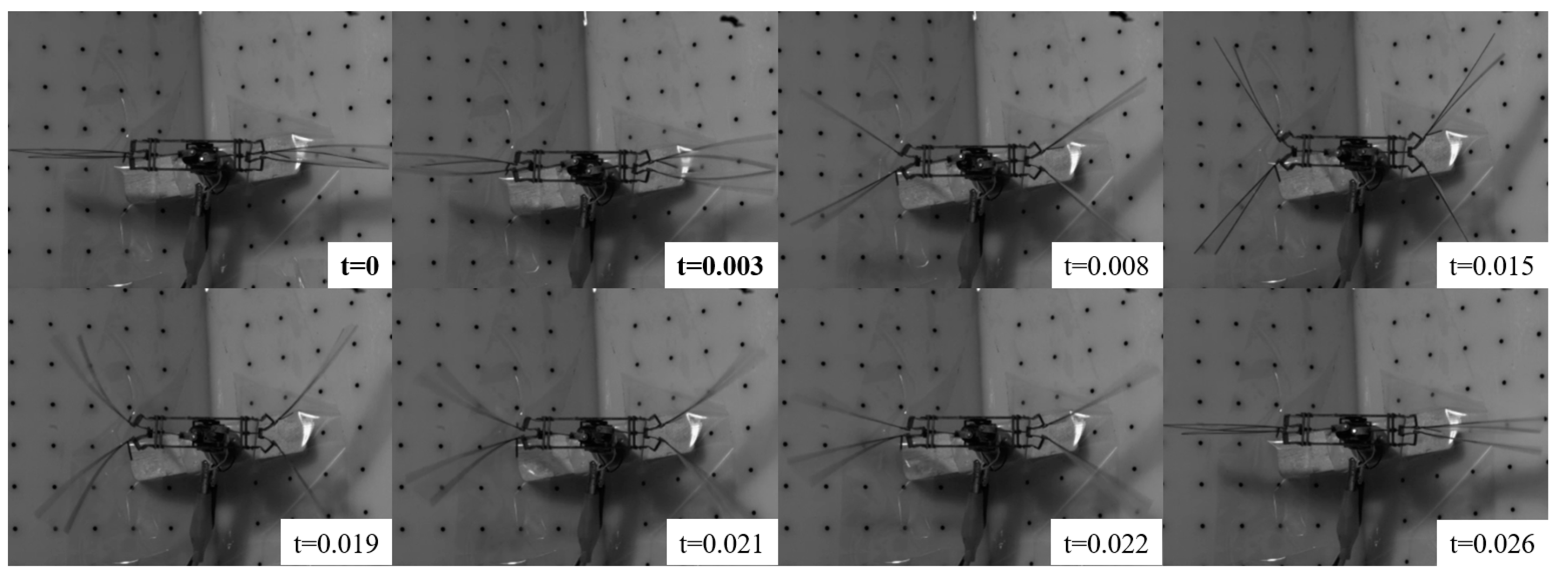
To observe wing motion, we employed a high-speed camera to capture images of the wings in motion. Since the structures on both the left and right sides were symmetrical, we selected one half of the structure for our analysis, and
Figure 9 depicts the resulting image. In order to synchronize the motor movements on both sides, we set the initial position to be the same, we can note that the synchronization of the motor can be maintained under 2.8 V and its frequency was 38 Hz.
Based on our findings, the duration of the wings' upstroke was longer than that of the downstroke, which can be attributed to the fact that during the upstroke, the compression of the flexure hinge creates a moment that must be overcome. Conversely, during the downstroke, the compressed force in the flexure hinge is released, thereby aiding in the reversal of the wings.
Figure 8.
Overview of the assembly process. (a) An exploded view of the layup. (b) Laminate into stake under predetermined pressure and temperature, release cut on the cured laminate is shown in white lines. (c) The released laminate. (d) Process involving folding of transmission manually, the wing attachment and stopper are attached on the transmission by cyanoacrylate adhesive, the stopper ensure that the flexure hinge folds to 90 degrees. (e) Slider with one flexible hinge that enable bend 53° in both directions, (f) the slider is sild into flexure hinges mechanism by designated slot, (g) two DC motors(DC motor 618), (h) The transmission and guideway are attached to the body with the mating features (M1 and M2), (i) Prototype and coin, the coin which diameter is 22.25 mm indicates the scale.
Figure 9.
The Motion of Wings under High-Speed Cameras (Phantom VEO-E 310L), the fps is 1000.
Figure 9.
The Motion of Wings under High-Speed Cameras (Phantom VEO-E 310L), the fps is 1000.
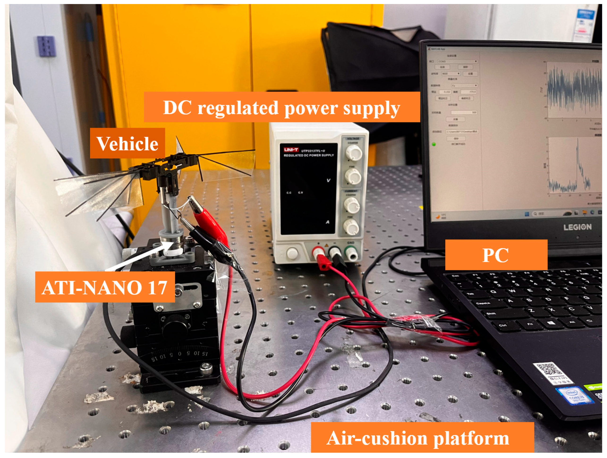
The frequency, lift, and wing flapping amplitude of the robot were assessed at different voltage ranging from 1.0 V to 3.6 V and intervals of 0.1 V. The experimental setup is depicted in
Figure 10.
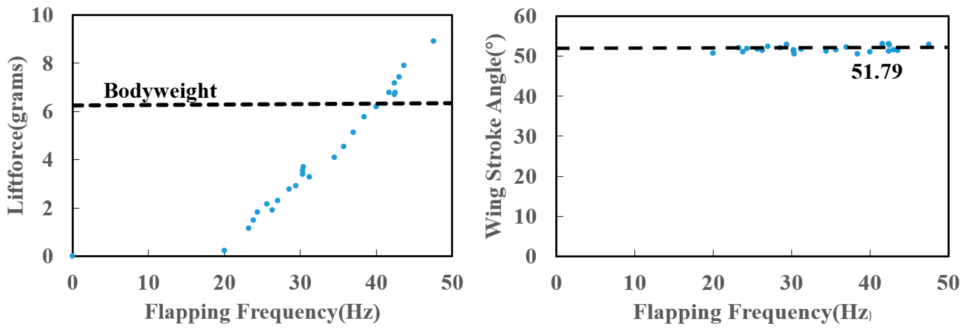
The lift force and wing stroke angle generated by the flapping-wing as a function of the wing beat frequency were shown in
Figure 11. The results demonstrate that the lift generated by the robot can surpass its own gravity when the frequency over 38 Hz (2.8 V). Additionally, the robot achieved a maximum flapping frequency of 47.6 Hz (3.6 V), resulting in a lift force of 8.92 g. While we observed a slight variation in the flapping amplitude of the robot, the average value remained consistent at approximately 51°.
Figure 10.
Setup of lift force test. The force sensor adopts ATI-NANO17 and uses a DC Regulated Power Supply to actuate the robot. The air cushion platform is used to isolate the irregular vibration of the environment.
Figure 10.
Setup of lift force test. The force sensor adopts ATI-NANO17 and uses a DC Regulated Power Supply to actuate the robot. The air cushion platform is used to isolate the irregular vibration of the environment.
Figure 11.
Lift force and wing stroke angle vs. frequency. The left figure shows the relationship between lift and frequency, The dashed black line indicates the weight of the robot. The right figure shows the relationship between wing stroke angle and frequency, the dashed black line indicates the average value of all measured amplitudes.
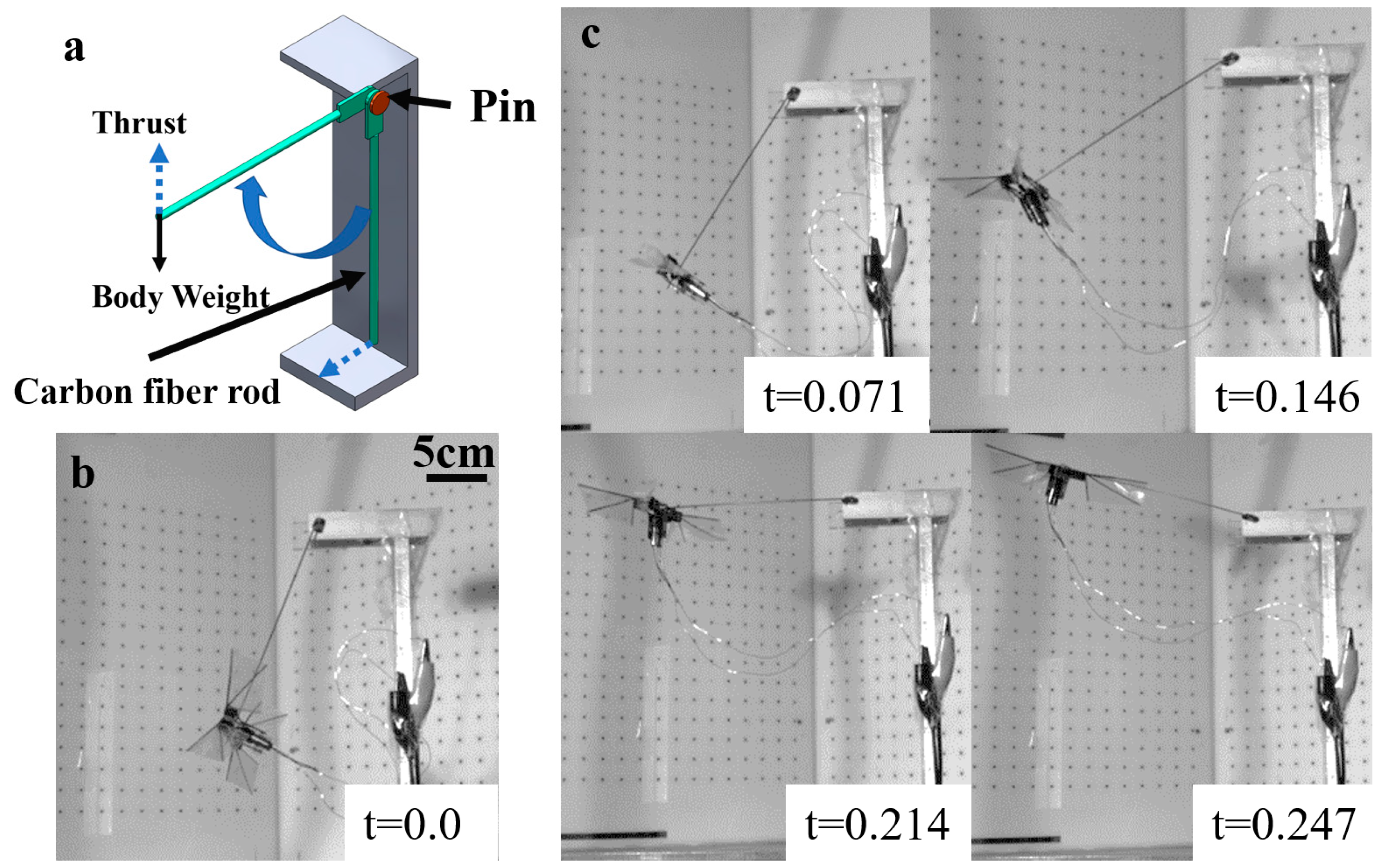
A simple pendulum method can be adopted to measure the thrust generated by the robot, a tethered flight test stand was shown in
Figure 12, the robot is installed at the end of the pendulum which made of carbon fiber rod. When powered on, the thrust generated by the robot will push the robot to move in a circular motion around the rotation center of the pendulum. When the robot moves to the horizontal line, we can consider the thrust generated by the robot to be in balance with gravity. Of course, this only demonstrates an observable effect of thrust. when the robot beat at 45 Hz (3.4 V), the robot was lifted above the horizon by the generated thrust.
Figure 12.
Tethered flight test. (a) A simple pendulum stand, the length of the carbon fiber rod is 17 centimeters. (b) Robot position in initial state. (c) Time sequences of robot when it is in a single pendulum motion.
Figure 12.
Tethered flight test. (a) A simple pendulum stand, the length of the carbon fiber rod is 17 centimeters. (b) Robot position in initial state. (c) Time sequences of robot when it is in a single pendulum motion.
5. Discussion
We present a novel methodology for the creation of a lightweight flapping robot, that using flexure hinges as the transmission. The robot attains a net uplift of 2 g, and despite its current incapability of carrying integrated circuits and batteries, it demonstrates the prospect of enlarging the employment of flexure hinges to flapping robots that exceed the weight threshold of 5 g.
However, a notable obstacle arises as the flapping robot is underactuated, with only a duo of actuators. The purpose of both actuators is to generate lift force, it cannot achieve three degrees of freedom flight. Further studies will seek to increase the count of actuators, which can increase the payload capacity of the flapping robot and achieve untethered controllable flight.
6. Conclusions
Our study proposes a new design approach, which employs a flexure hinge to develop a flapping robot weighing under 10 g. Through experimental methods, we verified the effectiveness of our design and successfully achieved insect-scale flight. Utilizing a high-speed camera, we captured the flapping motion of the robot, and further refined our prototype design based on these results. We observed a maximum flapping frequency of 47.6 Hz, generating a lift force of 8.92 g.
Moving forward, we aim to enhance the performance of our robot without increasing its scale, and integrate additional design features to enable a wider range of functions. Ultimately, we hope to achieve complete multi-degree of freedom flight, thereby fulfilling our mission of developing a versatile and efficient flying robot.
References
- Fry, S.N.; Sayaman, R.; Dickinson, M.H. The aerodynamics of free-flight maneuvers in Drosophila. Science 2003, 300, 495–498. [Google Scholar] [CrossRef] [PubMed]
- Dickinson, M.H.; Muijres, F.T. The aerodynamics and control of free flight manoeuvres in Drosophila. Philos T R Soc B 2016, 371. [Google Scholar] [CrossRef] [PubMed]
- James, J.; Iyer, V.; Chukewad, Y.; Gollakota, S.; Fuller, S.B. Liftoff of a 190 mg Laser-Powered Aerial Vehicle: The Lightest Wireless Robot to Fly. IEEE Int Conf Robot 2018, 3587–3594. [Google Scholar]
- Jafferis, N.T.; Helbling, E.F.; Karpelson, M.; Wood, R.J. Untethered flight of an insect-sized flapping-wing microscale aerial vehicle. Nature 2019, 570, 491–495. [Google Scholar] [CrossRef] [PubMed]
- Phan, H.V.; Aurecianus, S.; Au, T.K.L.; Kang, T.; Park, H.C. Towards the Long-Endurance Flight of an Insect-Inspired, Tailless, Two-Winged, Flapping-Wing Flying Robot. IEEE Robot Autom Let 2020, 5, 5059–5066. [Google Scholar] [CrossRef]
- Karasek, M.; Muijres, F.T.; De Wagter, C.; Remes, B.D.W.; de Croon, G.C.H.E. A tailless aerial robotic flapper reveals that flies use torque coupling in rapid banked turns. Science 2018, 361, 1089–1094. [Google Scholar] [CrossRef] [PubMed]
- Chen, Y.; Zhao, H.; Mao, J.; Chirarattananon, P.; Helbling, E.F.; Hyun, N.-S.P.; Clarke, D.R.; Wood, R.J. Controlled flight of a microrobot powered by soft artificial muscles. Nature 2019, 575, 324–329. [Google Scholar] [CrossRef] [PubMed]
- Ozaki, T.; Hamaguchi, K. Bioinspired Flapping-Wing Robot With Direct-Driven Piezoelectric Actuation and Its Takeoff Demonstration. IEEE Robot Autom Let 2018, 3, 4217–4224. [Google Scholar] [CrossRef]
- Fuller, S.B. Four Wings: An Insect-Sized Aerial Robot With Steering Ability and Payload Capacity for Autonomy. IEEE Robot Autom Let 2019, 4, 570–577. [Google Scholar] [CrossRef]
- Yang, X.F.; Chen, Y.; Chang, L.L.; Calderon, A.A.; Perez-Arancibia, N.O. Bee(+): A 95-mg Four-Winged Insect-Scale Flying Robot Driven by Twinned Unimorph Actuators. IEEE Robot Autom Let 2019, 4, 4270–4277. [Google Scholar] [CrossRef]
- Phan, H.V.; Park, H.C. Mechanisms of collision recovery in flying beetles and flapping-wing robots. Science 2020, 370, 1214–1218. [Google Scholar] [CrossRef] [PubMed]
- de Croon, G.C.H.E.; de Clercq, K.M.E.; Ruijsink, R.; Remes, B.; de Wagter, C. Design, aerodynamics, and vision-based control of the DelFly. International Journal of Micro Air Vehicles 2009, 1, 71–97. [Google Scholar] [CrossRef]
- Rosen, M.H.; le Pivain, G.; Sahai, R.; Jafferis, N.T.; Wood, R.J. Development of a 3.2g Untethered Flapping-Wing Platform for Flight Energetics and Control Experiments. In Proceedings of the 2016 IEEE International Conference on Robotics and Automation (ICRA); 2016; pp. 3227–3233. [Google Scholar]
- Ozaki, T.; Ohta, N.; Jimbo, T.; Hamaguchi, K. A wireless radiofrequency-powered insect-scale flapping-wing aerial vehicle. Nat Electron 2021, 4, 845–852. [Google Scholar] [CrossRef]
- Wood, R.J. The first takeoff of a biologically inspired at-scale robotic insect. IEEE Transactions on Robotics 2008, 24, 341–347. [Google Scholar] [CrossRef]
- Roll, J.A.; Cheng, B.; Deng, X.Y. An Electromagnetic Actuator for High-Frequency Flapping-Wing Microair Vehicles. IEEE Transactions on Robotics 2015, 31, 400–414. [Google Scholar] [CrossRef]
- Tu, Z.; Fei, F.; Deng, X.Y. Untethered Flight of an At-Scale Dual-Motor Hummingbird Robot With Bio-Inspired Decoupled Wings. IEEE Robot Autom Let 2020, 5, 4194–4201. [Google Scholar] [CrossRef]
- Wood, R.J.; Avadhanula, S.; Menon, M.; Fearing, R.S. Microrobotics using composite materials: The micromechanical flying insect thorax. 2003 IEEE International Conference on Robotics and Automation, Volumes 1–3, Proceedings 2003, 1842–1849. [Google Scholar]
|
Disclaimer/Publisher’s Note: The statements, opinions and data contained in all publications are solely those of the individual author(s) and contributor(s) and not of MDPI and/or the editor(s). MDPI and/or the editor(s) disclaim responsibility for any injury to people or property resulting from any ideas, methods, instructions or products referred to in the content. |
© 2023 by the authors. Licensee MDPI, Basel, Switzerland. This article is an open access article distributed under the terms and conditions of the Creative Commons Attribution (CC BY) license (http://creativecommons.org/licenses/by/4.0/).
