1. Introduction
Visible Light Communication (VLC) systems have been the focus of research and development for many years. Numerous VLC products have been developed and are commercially available such as Light Fidelity (LiFi) [
1]. The basic components of VLC systems include Light Emitting Diodes (LEDs) as transmitters and Photo-Detectors (PDs) as the receivers. At the transmitter end, the information bits are converted into electrical signals to drive LEDs, while at the receiver end, the photons are received by PDs and converted back to information bits. VLC systems use the visible light spectrum instead of the Radio Frequency (RF) spectrum. The wide interference-free range of the visible light spectrum,
, is one of the main advantages of VLC systems over RF systems. VLC systems also provide a higher data rate [
2,
3]. VLC systems may not replace RF systems completely, however, these systems can be used as hybrid technologies to improve communication quality for different applications and environments [
4].
VLC systems are used for both data communication and illumination. This leads to a wide range of applications [
5]. Indoor environments are prime examples of the application of VLC systems due to the availability of pre-installed infrastructure for the transmitters and the receivers [
6]. In [
7], the authors proposed an indoor VLC system based on On-Off Keying (OOK) using four devices equipped with 3600 LEDs
which were installed in a room of dimensions
. The authors concluded that the system can satisfy communication requirements for the indoor environment. In [
8], a data rate of about
was achieved using blue LEDs for an indoor environment. The laser-based white light emitting Surface Mount Device (SMD) platform combined with blue LEDs is proposed in [
9], the proposed framework achieved a data rat of about
with
times more brightness as compared to the conventional light bulbs.
Indoor positioning methods using VLC technologies have been reported in numerous studies. The features such as Received Signal Strength (RSS), Time of Arrival (ToA), and Angle of Arrival (AoA) are the most prominent when designing an indoor positioning system. The first, high-precision VLC-based indoor positioning system was proposed in [
10]. The proposed algorithm uses RSS measurement to obtain user/object location with an accuracy of
. In [
11], AoA is used as a feature to find the user/object location with the accuracy of
. The proposed framework used image sensors instead of PDs. The hybrid approach using a combination of RSS and AoA for improved communication and localization is proposed in [
12,
13]. In the aspect of cost-effectiveness, [
14] proposed a two-stage framework. First, presented a dedicated analog sensor that is capable of being directly plugged into the microphone input of a computer or a mobile device such as a smartphone. The signal pattern, as well as the signal strength of a beacon, can both be decoded by it. Second, to decode the signal pattern, the use of rolling shutter cameras is proposed. This offers a viable answer to the problem of localizing hand-held devices that contain cameras.
Artificial Intelligence (AI) methods have been widely developed for the application of indoor positioning mainly due to high accuracy and easy deployment [
15,
16]. The machine learning-based classifiers are compared for localization in an indoor environment in [
17]. It has been reported that the k-nearest neighbor (k-NN) algorithm performed the best among all other classifiers. It has been reported in [
18], that support vector machine (SVM) outperformed logistic regression using the fingerprinting method for Bluetooth signals in an indoor environment. In [
19] Principle Component Analysis (PCA) is used to improve the performance of SVM, K-NN, and random forest classifiers for indoor positioning. In [
20], it is reported that the random forest classifier outperforms K-NN for WiFi-based indoor positioning. In [
21], an enhance random forest algorithm is proposed for indoor positioning in real-world settings. Inspired by the literature, this paper compares the performance of SVM and random forest regression (RFR) for VLC-based indoor positioning.
VLC technologies have been used for a variety of autonomous systems such as vehicles, autonomous ground robots, and fixed robotic industrial grippers. In [
22], an in-hospital transportation robot called HOSPI is developed and VLC technology is used to improve navigation and localization in addition to other navigation sensors for better autonomous control of the robot. The study explores the localization and autonomy using experimental and actual results in an actual hospital. In [
23], the multi-frequency method with RSS is used to measure the distance of the robot from each LED that is installed above the robot in a plane that is parallel to the plane of the robot base in order to accomplish precise indoor positioning. This is accomplished by installing the LEDs in a plane that is perpendicular to the surface of the robot base. A multi-frequency technique is one in which each LED transmits its location ID at a frequency that is distinct from the others. In [
24], VLC technology in addition to the Extended Kalman filter has been used for communication and localization in underwater robots for nuclear reactor inspection. In this research, a system is described that makes use of the modulated light signal both as a medium through which data can be sent and as a reference upon which to base the positioning of a mobile robot. Both of these functions are carried out by the same system. VLC technologies have been proven to be efficient and cost-effective. The underlying modulation and multiplexing techniques have constantly evolved to meet the needs of more complicated and dynamic environments.
Many different approaches, such as Orthogonal Frequency Division Multiple Access (OFDMA), Time Division Multiple Access (TDMA), and Code Division Multiple Access (CDMA), have been suggested in the research literature as methods for implementing multiple access in very low bit rate (VLC) systems [
25,
26,
27,
28,
29,
30,
31]. MIMO-OFDM is utilized for multiuser VLC systems in [
32], and this is accomplished by giving each user their own unique carrier. In the same vein, CDMA is used in conjunction with OFDM to support multiple-user communication rather than sending a single carrier to each user. Similarly, Non-Orthogonal Multiple Access (NOMA) methods have been widely proposed in VLC systems to increase the number of users without compromising on performance [
33]. In the power domain NOMA, the data of different agents are accumulated together using different power factors for each agent, and Successive Interference Cancellation (SIC) is used to retrieve the data at the receiver end. However, the resource allocation for the power domain NOMA is highly affected by the channel and environment.
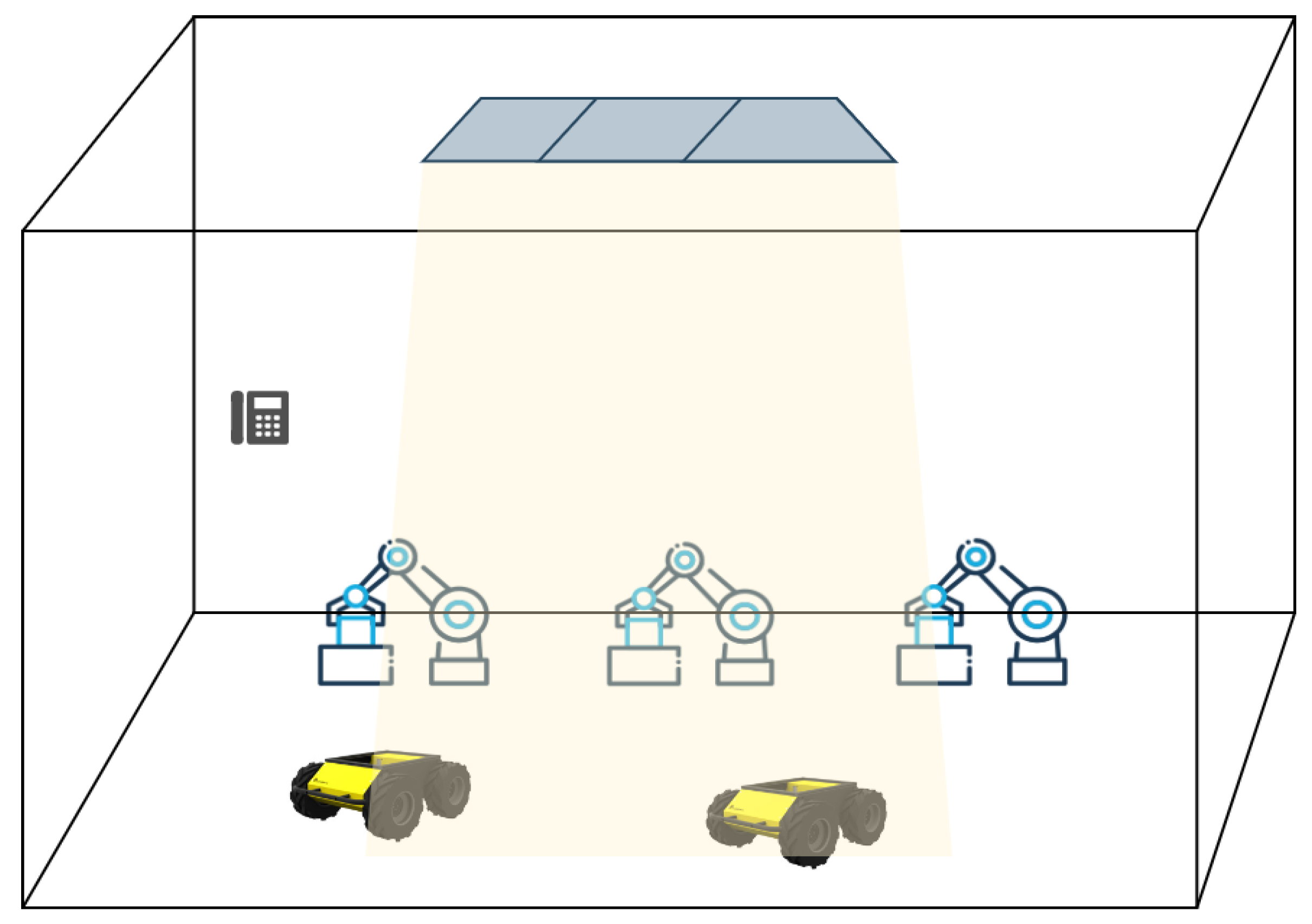
Figure 1.
General indoor environment for collaborative tasks with LED arrays for transmission.
Figure 1.
General indoor environment for collaborative tasks with LED arrays for transmission.
The resource allocation in NOMA has been a focus of research for many years [
34]. In [
35], the subject of energy-efficient user planning and power optimization in NOMA wireless links is investigated to understand the trade-off that exists between the data rate effectiveness and the amount of energy that is consumed by NOMA. For the downlink NOMA heterogeneous network, energy-efficient user planning and power distribution techniques are presented for both perfect and imperfect CSI, respectively. In [
36], the neural network-based resource allocation method is proposed for mobile users with mutual interference management. This research work also provides priorities and rate demands-based user scheduling methods to coordinate the access of heterogeneous users with limited radio resources. In [
37], a low complexity power allocation scheme for NOMA-based indoor VLC systems which is called the Simplified Gain Ratio Power Allocation (S-GRPA) scheme is proposed. The Channel State Information (CSI) used for power allocation in NOMA is obtained through the look-up table method rather than calculation. In this research work, the location of the agent is received at the base station by a separate low-energy communication link. This approach suffers the loss of the signal-carrying position information. Inspired by this approach, we proposed to use machine learning algorithms to find the location of the agent for CSI for better dynamic resource allocation in NOMA for a collaborative indoor environment instead of the separate communication link. Additionally, to avoid loss of agent location due to shadowing or obstacles, we used Euclidian Distance Matrix (EDM) to obtain the location of agents using mutual distances of agents in the network.
The rest of the article is structured as follows.
Section 2.2 provides a mathematical discussion on the S-GRPA for NOMA, followed by
Section 2.1 which discusses the VLC channel.
Section 2.3 &
Section 2.4 discusses Random Forest Regression (RFR) and Support Vector Machine (SVM) algorithms. The
Section 2.5 discusses the Euclidian Distance Matrix (EDM) to obtain an agent’s location in the event of signal loss due to shadowing and obstacles.
Section 3 presents results for indoor positioning and bit-error-rate (BER) for NOMA-based VLC system. The article is finally wrapped up with concluding remarks.
2. System Design
In this research work, a complete framework for resource allocation for power domain NOMA using S-GRPA, in the indoor environment for collaborative tasks, is proposed using visible light communication systems as shown in
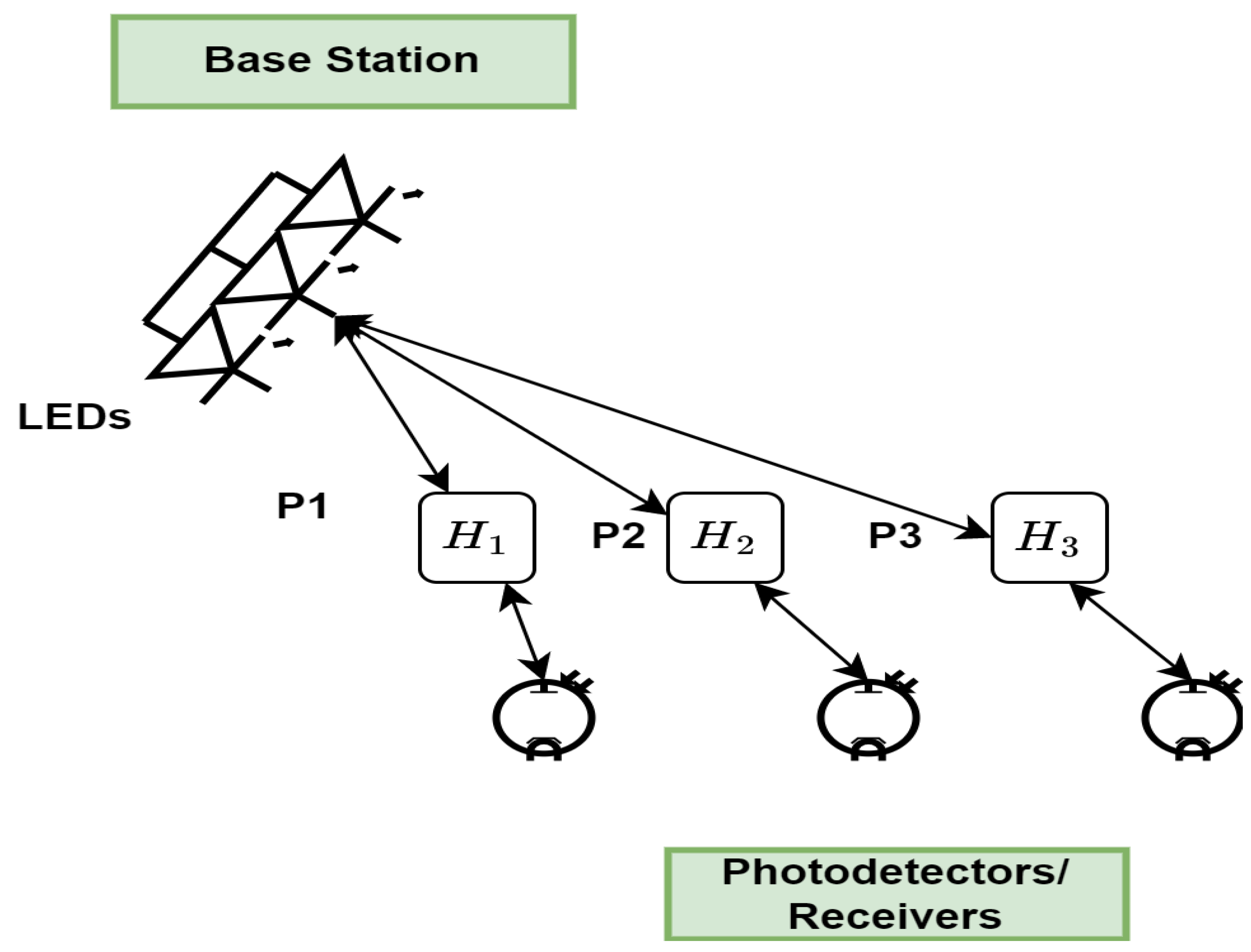
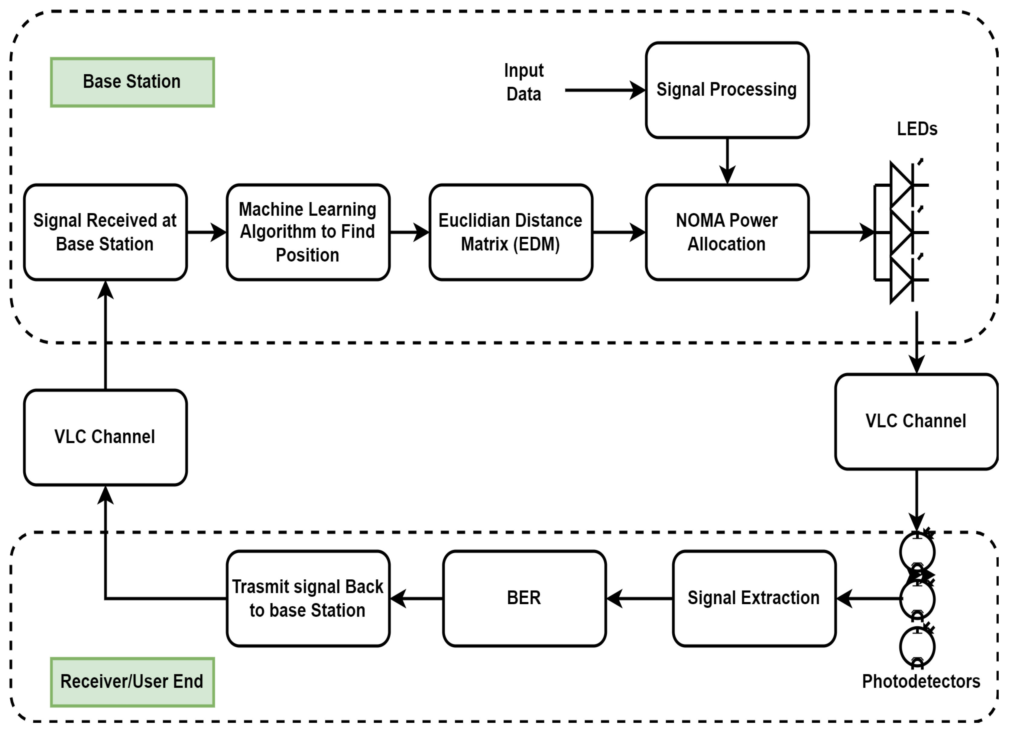
Figure 1. For indoor positioning, we have compared the RFR and the SVM algorithms with Euclidian Distance Matrix (EDM). The complete system block diagram is shown in
Figure 2. The next section discusses the S-GRPA for NOMA with VLC channel model.
2.1. Visible Light Communication (VCL) Channel
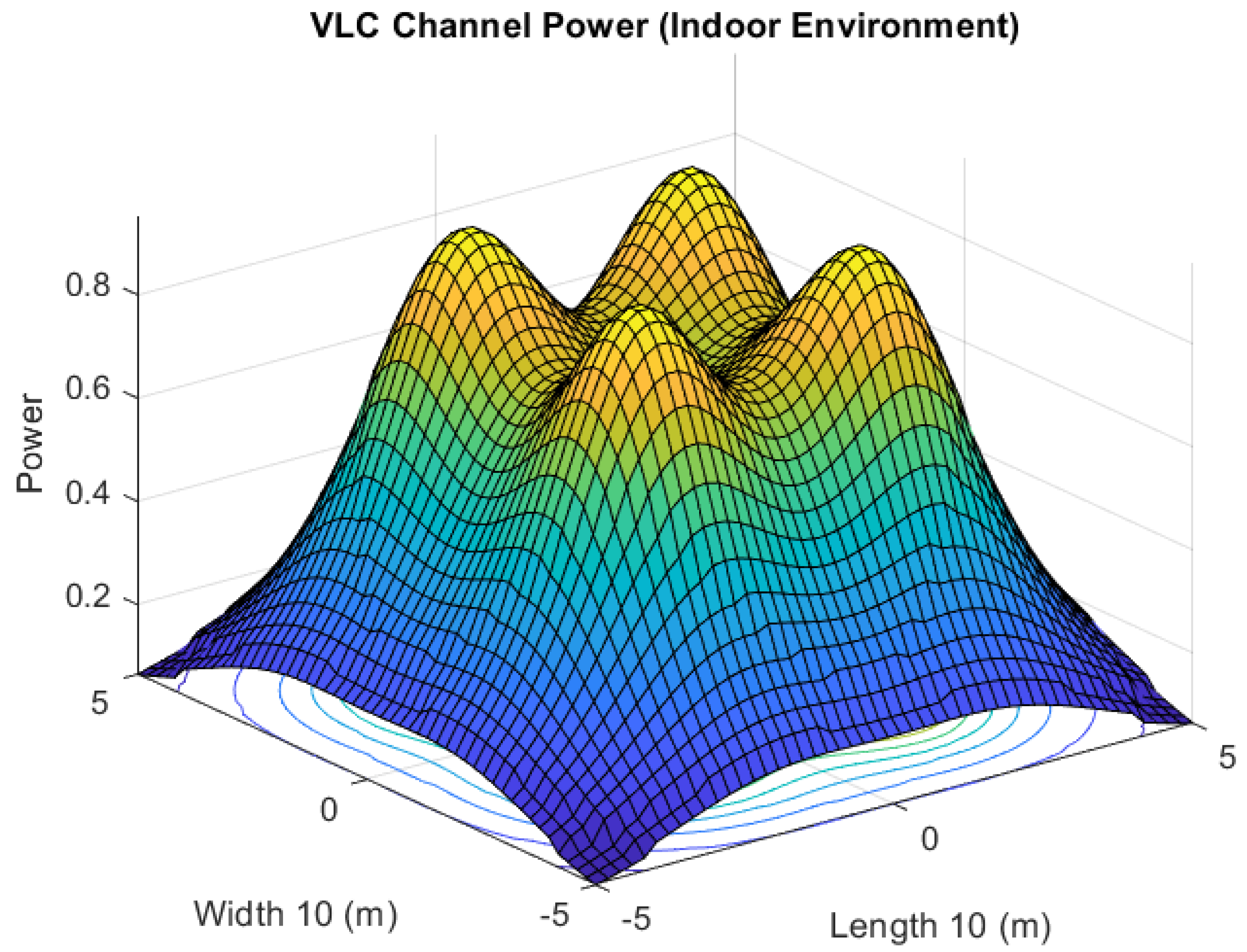
LEDs, the transmitting devices in VLC, serve dual tasks by providing both light and data transmission. As can be seen in
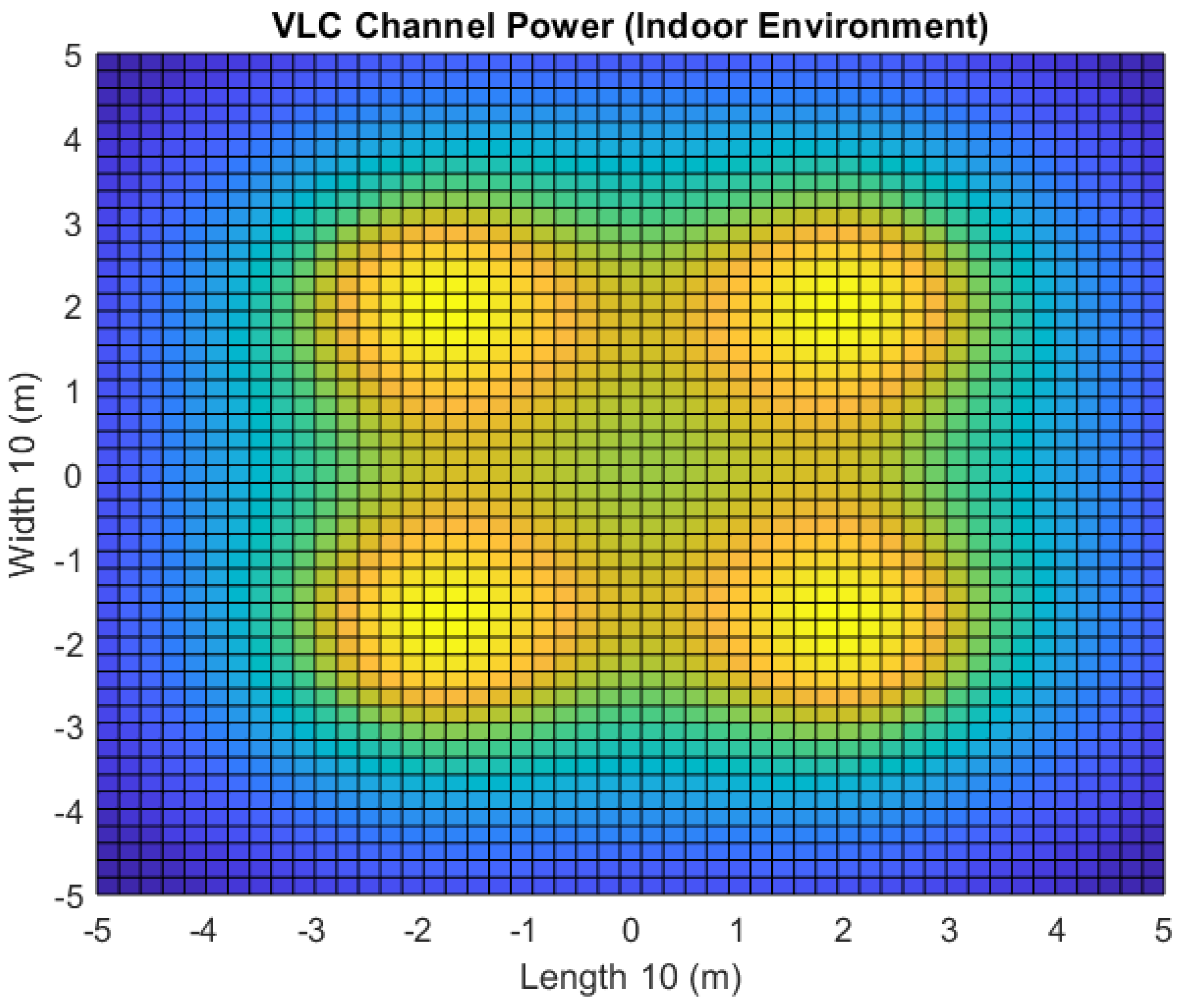
Figure 3, the responsiveness of the VLC channel in an indoor setting is heavily dependent on the illumination intensity and the transmission power. The illumination intensity at a point in the Cartesian plane is given as follows [
38]:
where
is the intensity of the central light source,
, is the order of Lambertian emission,
d is the separation distance between the LEDs and the PDs, and
and
are the irradiance and incidence angles, respectively. Lambertian emission,
, is described in the following order:
where
is the angle at half illuminance of an LED. The signal power received at a particular PD is given as follows:
where
is the filter transmission,
is concentrator gain and
is the field of view of PD.
is transmitted signal power, it fades through Line of Sight (LoS) channel gain. The DC gain of the LoS path is given as follows:
The distance, d, between the transmitter and receiver is the key factor in the allocation of signal power in NOMA-based communication systems. The next section discusses the mathematical basis for NOMA and resource allocation in this method.
2.2. Simplified Gain Ratio Power Allocation (S-GRPA) for NOMA
Several agents’ data are combined using the power-domain NOMA, and data is then separated using SIC. NOMA is free of spectrum spreading or degraded SNR performance, in contrast to other multiple access methods such as OFDMA and CDMA [
39]. Several agents using the same resource simultaneously in NOMA boosts system throughput, but each agent has a distinct power factor. In this study, we employ symbol-level NOMA.
Figure 5 illustrates the NOMA framework for three agents.
Figure 4.
2D view of power distribution of VLC channel in an indoor environment with four transmitting locations.
Figure 4.
2D view of power distribution of VLC channel in an indoor environment with four transmitting locations.
Because of the relative difference in distance from the base station, the agent near the cell edge gets a lot more power than the agent at the center of the cell. The received signal can be expressed as follows [
39]:
where
and
are, the suppressed information from all agents, received at each agent. The information from agent-1 is separated and demodulated as follows at the receiver end:
After agent-1’s data has been retrieved, agent 2’s data is recovered by SIC reducing agent-1’s interference in the manner described below:
This method can be expanded to a higher number of agents. As the power factor,
p, for each agent depends on its location. The power distribution of the VLC system is shown in
Figure 4, it can be seen that overall power distribution can be divided into zones,
, with radius,
. Here
refers to the radius of each zone. Furthermore, zone
N has the least illumination intensity, and zone 1 has the highest illumination intensity. The
region can be defined as follows [
37]:
for
where
is the maximum radius of the last zone. The relationship between the
agent and the
agent in terms of power allocation is described as follows [
37]:
Here, the information on channel gain, H, is received by the indoor positioning algorithm and stored in the look-up table.
Figure 5.
Illustration of NOMA method for VLC systems
Figure 5.
Illustration of NOMA method for VLC systems
2.3. Random Forest Regression Algorithm
The idea of aggregating random decision trees was initially presented in the research papers[
40,
41,
42]. This idea is at the heart of the RFR technique. The following is the formulation of the problem statement for the RFR algorithm:
Problem 1. Calculate the value of the non-parametric regression function denoted by →, where p is the dimension of the input vector and is the input vector used to estimate the output, .
Using the training data set, the RFR method predicts the function
, which is similar to the actual regression function
, and then compares the two.
is a mathematical expression. The error function can be written as:
, as
. The random forest methodology employs
N different types of regression trees. The input vector,
, is evaluated on each tree in such a way that the projected value for the
tree is given as follows [
41]:
here,
are the independent random variables associated with each regression tree.
are the data points selected prior to the construction of trees.
is the zone containing
and
is the number of data points fall into
.
2.4. Support Vector Machine Algorithm
As with the RFR algorithm, the purpose of the Support Vector Machine (SVM) regression algorithm is to map the input
to the desired output
y. Instead of minimizing the discrepancy between the estimated and true regression functions,
and
f, respectively, SVM penalizes the final result so that it can be used in linear regression.
. Let
y be the true output, and inside an area defined as
, SVM will make its predictions. The discrepancy between actual output,
y, and expected output,
z, is denoted by the
. Two slack variables are added as a penalty if the projected output is outside the region
.
indicates that the projected output lies above the region of
, whereas
indicates that the predicted output lies below the region of
. The following is the error function for the SVM regression algorithm: [
43,
44,
45,
46,
47]:
subject to:
C is the tunable variable that controls the penalty on slack variables and
. To solve (
13), following Lagrange multipliers are introduced [
43,
47]:
This transforms (
13) in following:
Now differentiating (
16) to 0, with respect to each variable as below [
43,
47]:
The Dual form of the Primary
can be defined as follows:
subject to:
The predicted output can be written as [
47]:
This concludes the regression algorithms to obtain the location of the agent based on power received at the receiver. However, in real-world settings, the direct receiver might not be able to receive the agent’s signal due to obstacles or the signal is highly disrupted due to noise. Therefore, for localization in collaborative indoor environments, the distance geometry problem plays an important role by obtaining the location of the particular agent using the mutual distances of all agents in the network. The next section discusses the distance geometry problem using Euclidian Distance Matrix (EDM).
2.5. The Distance Geometry Problem
The VLC systems for indoor environments with dynamic agents often face the loss of signal due to shadowing because of obstacles. To assist the localization in the event of signal loss in a multiagent collaborative environment, the Distance Geometry Problem (DGP) is used in conjunction with the machine learning algorithms discussed in the previous subsection. The objective of the DGP is to find the location of agents using their mutual distances. It is important to mention that agents do not only communicate with the base station during collaborative tasks but also communicate with each other, this provides extra information about the environment that agents transmit to the base station.
The mutual distances of agents are provided in the form of EDM. The solution to DGP for N agents in dimension, d, is a matrix, , here are the coordinates for agent. The mutual distance between agents can be referred as , here is the distance from agent to agent. To generate an initial estimate of the matrix , multi-dimensional scaling is used. The estimated point cloud, can be mapped to the actual matrix, S, using rigid transformation in absolute coordinates. For this transformation, the Procrustes Analysis is performed which is spectral factorization. For this process, it is assumed that the location of some agents, is known, these agents are referred to as anchors. To find the location of missing agents in the network, DGP can be stated as static.
Table 1.
Simulation Parameters.
Table 1.
Simulation Parameters.
| Parameters |
Value |
| Dimension |
6.3 x 2.5 x 2
|
| Tx-Rx (LED arrays-PDs on agents) Configuration |
4X4 |
| No. of LED Arrays |
4 |
| No. of LEDs in single Array |
60 |
| Total Power |
20 watts |
| Semi-angle at half power |
70 degrees |
| PD field of view |
60 degrees |
| Refractive Index |
1.5 |
| No. of Agents |
5 |
The static DGP consists of three stages to obtain the matrix,
S from the matrix,
D. The first stage is to obtain a Grammian matrix,
, it has one-one relation with matrix,
D. The Grammian matrix,
G, can be obtained by following the optimization problem [
48,
49]:
where
is a function, which maps the Grammian matrix,
G, to the matrix,
D.
W is referred to as a binary mask matrix, the entries with zero values in this matrix show the missing measurement of the received power and ∘ is the Hadamard product. The next stage is to obtain the matrix,
S, using the Grammian matrix,
G. The estimate,
can be obtained by the Singular Value Decomposition (SVD) method given that matrices,
G, and
S hold the mathematical relation,
.
As mentioned earlier that matrix,
can be mapped to the actual matrix,
S, using rigid transformation along with the information of
anchors. By denoting the columns of the matrix,
S, related to anchors as
and assuming
refers to the same columns in
. Furthermore, to make the
and
centered at the origin, assume that
and
are the translated version of
S and
Y. The transformation
can be defined as follows:
The actual matrix,
S can be calculated as follows:
where
and
refer to the centroids of
and
respectively.
This concludes the mathematical basis for the proposed framework for resource allocation using precise positioning of the agent in a collaborative indoor environment using VLC systems. The next section discusses the performance of indoor positioning using SVM and RFR algorithms, and bit-error-rate (BER) for NOMA-based VLC system.
3. Results
In the context of this research, a rectangular indoor environment that is analogous to
Figure 1 is being studied. The rectangular environment has a width of 6.3
m, a depth of 2.5
m, and a height of 3
m. These dimensions represent the area of the environment. Each Cartesian point has a zone that corresponds to it that is represented by a square cell that is 0.3
in size. The detailed simulation parameters are shown in
Table 1. The purpose of this exercise is to make an estimation of the Cartesian location within the square cell region and use this information to calculate channel gain for resource allocation for NOMA.
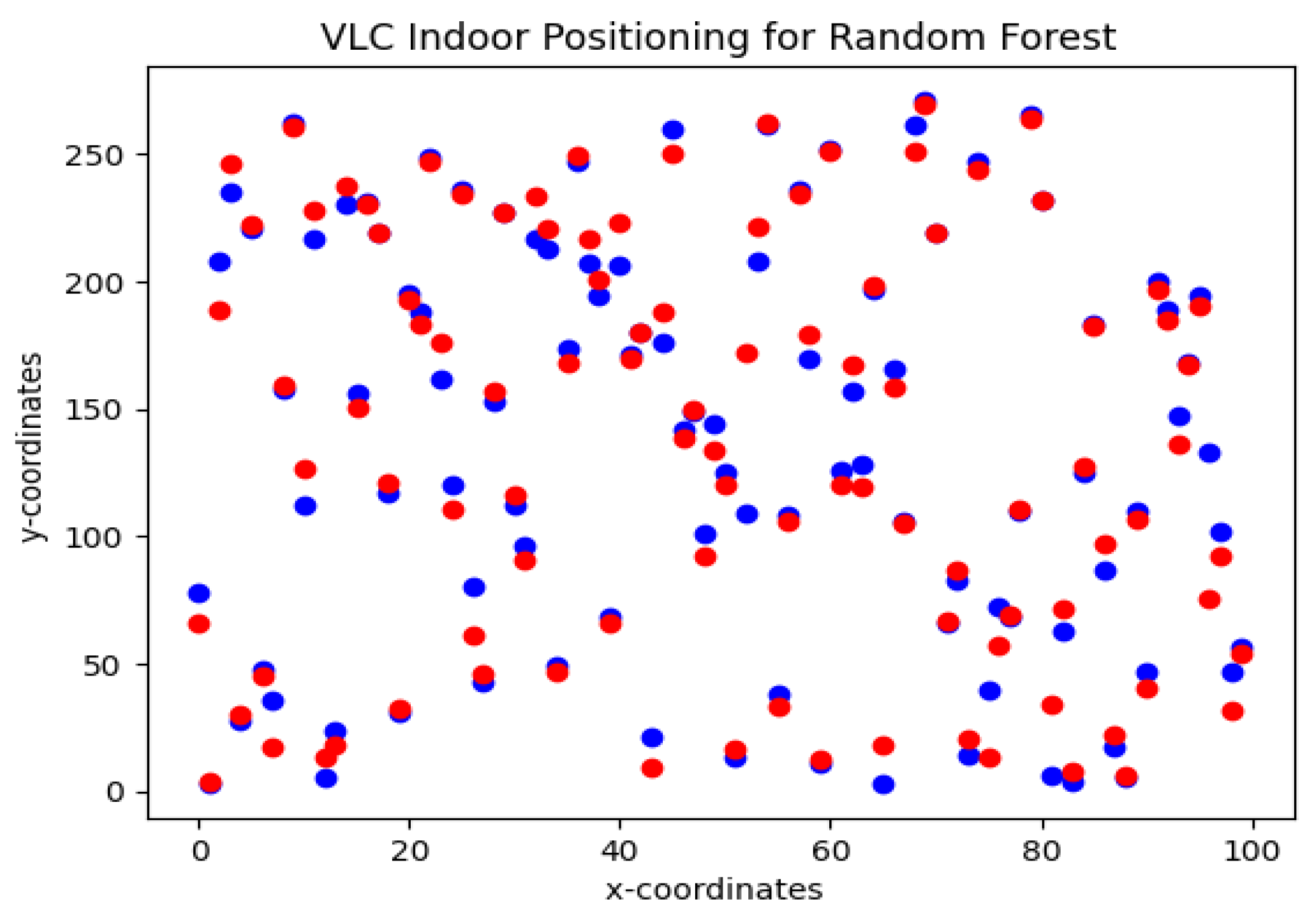
Figure 6.
VLC indoor positioning using Random forest regression algorithm. actual data points (blue), predicted data points (red)
Figure 6.
VLC indoor positioning using Random forest regression algorithm. actual data points (blue), predicted data points (red)
To obtain the location of agents, the SVM and RFR algorithms are trained using RSS and AoA features at the receiver end. Due to
Tx-Rx (LED arrays-PDs on agents) configuration for each agent, each feature has a dimension of
. The dataset is collected in MATLAB using the VLC channel. Each agent has a region of confidence of 0.25
m for its location.
Figure 6 shows the estimated and actual Cartesian coordinates of agents. For this simulation, the agent is considered to be dynamic, therefore, different locations are estimated in these simulations for more robustness in the algorithm. The red dots are actual coordinates and the blue dots are estimated values. For RFR, 100 decision trees are used in this simulation. The RFR shows an accuracy of 93.6% with an estimation error of
.
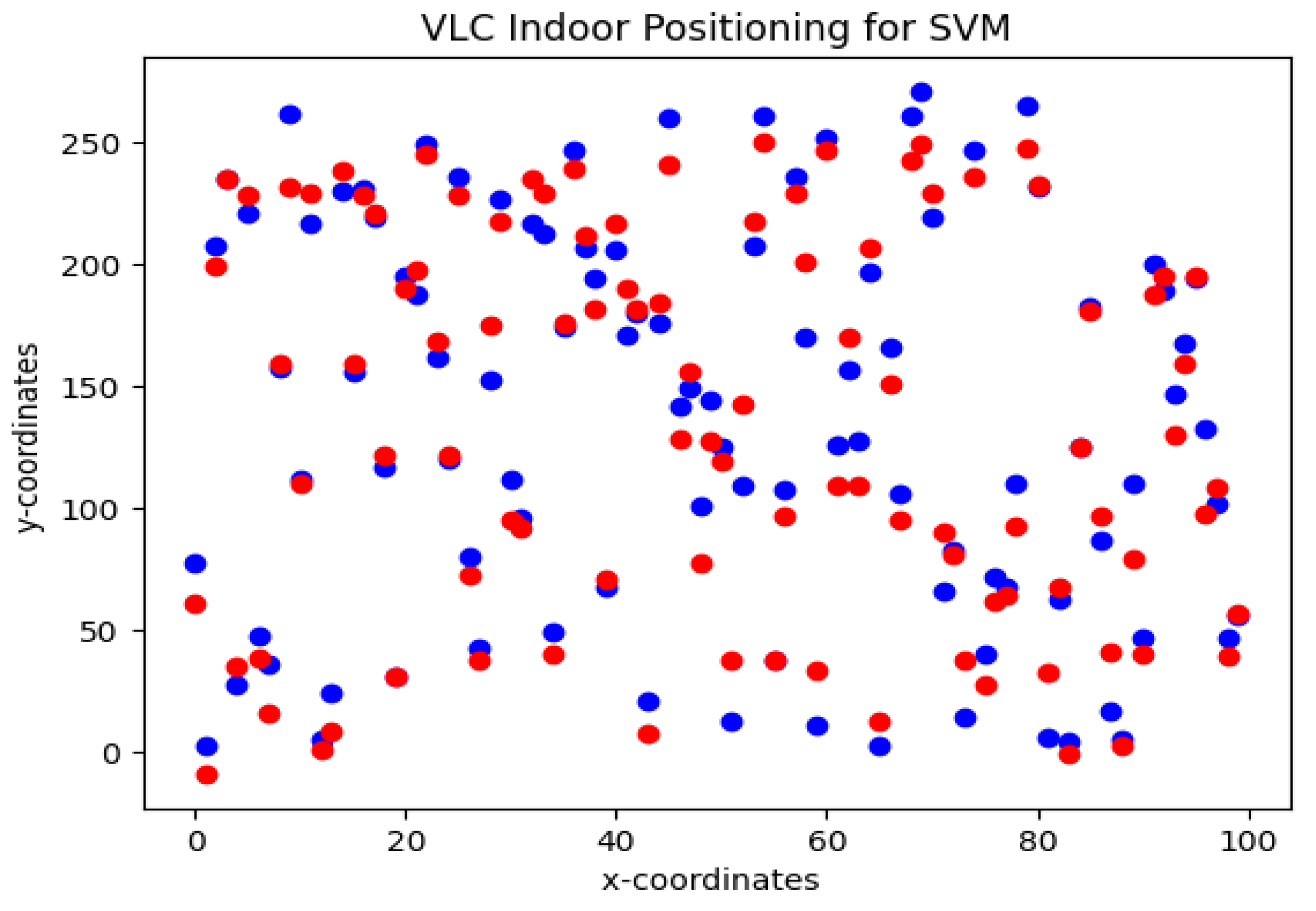
Figure 7 shows the results of the estimated location using the SVM algorithm. For SVM algorithm radial basis function is used to solve the error function. The SVM shows an accuracy of 84% with an estimation error of
. According to the findings of the statistical analysis, the mean error for the SVM regression method is higher than the mean error for the random forest regression technique. Therefore, RFR is used as a positioning algorithm in conjunction with S-GRPA for power allocation in a NOMA-based multi-agent VLC system.
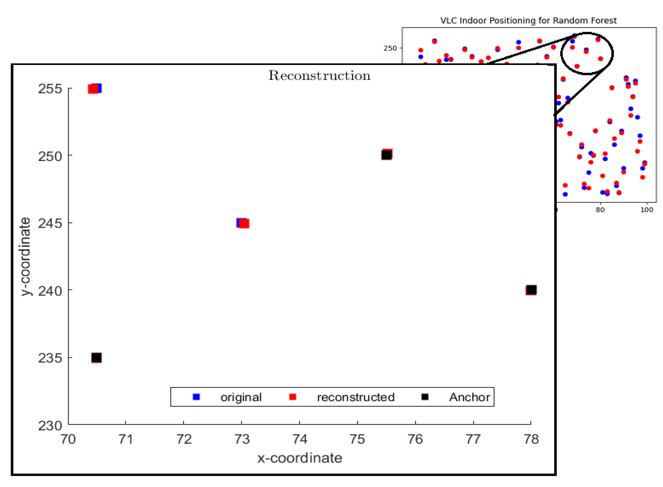
Figure 8 shows a scenario of five agents where the signal of two agents is not received at the base station due to obstacle/shadowing. In this scenario, the location of the other three agents is predicted by the RFR algorithm and used as anchors for EDM as shown by black data points. The red square boxes in
Figure 8 show the estimated position of two remaining agents using EDM. it can be seen that EDM with RFR predicted the locations precisely. Here the predicted position of anchors (black boxes) is considered to be accurate during the process of EDM.
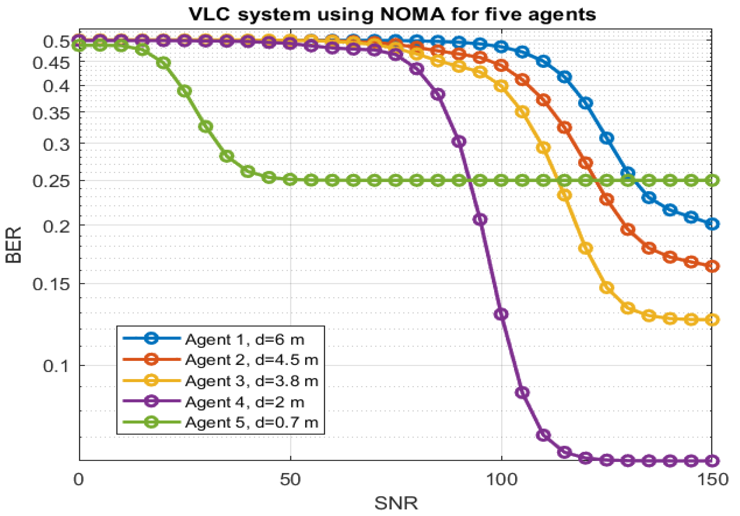
By combining the RFR algorithm with S-GRPA for power factor allocation in the VLC system,
Figure 9 shows the BER curves for five agents at different locations. The results consist of a Signal-to-Noise Ratio (SNR) between 0 to 150. The blue curve shows agent-1 at a distance of 6
m inches which is the farthest agent in the NOMA setup. The orange curve shows the BER rate for agent-2 at a distance of 4.5
m in an indoor environment. The yellow curve shows the BER for agent-3 at a distance of 3.8
m. The purple and green curves show the BER curves for agent-4 and agent-5 at distances of 2 and 0.7
m respectively. As expected the BER for the closest agent shows sharp and quick decay however, the farthest agent shows slow and high BER values. The power factor for each agent is allocated based on the location found by the RFR algorithm. It can be seen that S-GRPA with RFR is able to allocate appropriate power factors to each agent based on the location in an indoor environment.
