1. Introduction
In the area of polymer science, the propagation of conductivity (redox) front in conductive polymers, immersed into electrolytes was studied quite intensively. Olle Inganas [
1] with coauthors studied the propagation of conductivity (redox) front from conductive electrode and through the film, immersed in the electrolyte solution in polythiophenes, using change of their absorbance. The front propagation was found to be caused by the red-ox processes in polymers, changing their oxidative state, which can propagate along the polymer film to very long distances due to electron conductivity, transferring charge carriers (mainly electrons, but locally ions to counter-balance the electron transfer red-ox processes) to or from the front, where reduction or oxidation processes, involving electrons, are taking place. They found propagation speed to be quite high and distances, to which front propagated to be quite long (up to several centimeters).
They also found the dependencies of speed of front propagation on electrode potential and suggested a theoretical model, describing front propagation, based on polymer electrochemistry.
Aoki et al [
2] for the first time observed the propagation of Red-Ox front in polyaniline in liquid electrolyte using optical microscope, observed the red-ox front propagation in polythiophene [
3] and polypyrrole and suggested a descriptive model based on the percolation theory [
4]. Aoki and co-authors further observed the change of mechanism of front movement from propagation control to the diffusion control with the change of the solvent [
3].
At the same time some theoretical papers [
5,
6] suggested the analytical models behind the conductive red-ox front propagation, based on ion diffusion into or from the film and electron transport along the polymer. In [
5] it was found, that the limiting process, which determines the speed of front propagation, is the diffusion of anions out of or into the film, balancing the electroneutrality in the process of cations involved in the red-ox processes inside the polymer. Similar optical approach was currently used also to reveal resistance variation.
Memristive devices are thought to be perspective elements for neural networks development, due to the possibility to store the analog manifold of weights of connections in rate-based or spiking neural networks and to change them in a programmable way. After the HP paper, where it was claimed the experimental realization of TiO
2 memristor [
7], there was an explosive interest to memristors study, with many different physical systems found to exhibit the memristance behavior, like metal filament based systems [
8,
9], magnetic spin torque systems [
9], systems, having ion and electron conductivity [
3,
10]. At the same time there was a significant effort on developing ReRAM (resistive multi-level memories), based on change of the red-ox states of some complex organic molecules in nanometer thin layers [
11]. In mentioned paper it was shown, that metal-organic molecule, having a manifold of red-ox states, can programmably switch between different red-ox states by applying corresponding potentials and this process is reversible up to 40 000 cycles. This study showed the applicability of change of Red-Ox states in organic substances to manufacture real electronic devices.
The fact, that polyaniline (PAni) can be switched between red-ox states, having significantly different conductivity and good mechanical properties, makes it perspective candidate both for ReRAM and neural network elements.
The phenomenon of memristance in PAni was first observed in 2005 [
12], even if the term “memristor” was applied to the device only in 2008, after the HP group publication [
7], and the prototype of memristor was developed, having 3 terminals, similar to source, drain and gate of electrochemical transistor. The polyainiline memristive device was found to have up to 10
5 ON/OFF ratio [
13], thanks to its switching mechanism (based on the redox activity of the conductive polymer) and endurance more than 10
4 cycles [
14,
15] that allows the access to multiples and stable resistive states.
The necessary prerequisite for the operation of polymer memristive device is the presence of electron conductivity, combined with ion conductivity, which allows ions migration to some area of polyaniline and electrochemical process of oxidation or reduction, accompanied by change of polymer chain conductance due to change of it’s red-ox state [
16,
17].
Polymeric memristors (including, but not limited to PAni-based devices) possess several significant advantages over inorganic ones, consisting in absence of first cycle so-called “electroforming”, continuous spectrum of red-ox states within at least 5 orders of magnitude range , good reversibility and maybe the most important – there is no scattering of the values of the switching voltages from and to conducting states: for inorganic devices we can see scattering of these values not only for different devices, but also for the same device in different cycles. Their operation is predictable and fully described by polymer electrochemistry. It has been shown that PAni memristive device can work effectively in a pulse mode[
18] and its endurance is not less than 10
4 cycles [
16,
17], what makes this kind of memristive devices suitable for several practical applications. A number of simple neural networks were manufactured, based on polymer memristive devices, and algorithms for supervised learning were developed, allowing the training of memristor-based neural networks, such as single [
19] and double [
20] layer perceptrons at the hardware level.
It was shown also [
21], that the behavior of PAni-based memristive devices, which is used for spike propagation, can be controlled in the frame of STDP (Spike Timing Dependent Plasticity) algorithm, which is considered currently as the main paradigm of the explanation of unsupervised learning.
Despite the extensive study of polyaniline memristive devices [
22,
23], this element has a three-terminal structure, similar to ion field effect transistors (even if it acts a two-terminal device with respect to the external circuit), what makes difficult its application to real large scale neural networks having millions of neurons, which require mostly two terminal memristor devices.
Spiking neural networks, inspired by biological processes in neurons, which are called 3d generation neural networks [
24] attracted a lot of interest of scientific community due the possibility to be used in all neural networks applications and having many advantages such as the possibility of unsupervised learning due to STDP mechanism, low power consumption of hardware realizations, more simple architectures of spiking networks in comparison with 2
nd generation rate-based neural networks. A number of companies developed spike based processor architectures, like IBM True North and Intel Loihi, which successfully solve complex neural networks deep learning problems. The introduction of miniaturized high density spiking networks will allow the next generation of neuromorphic computation and bring us a bit closer to Artificial General Intelligence.
Here we report the study of the conductive red-ox front propagation directly applied to a working PAni based memristive device in which we explored in details the role of the device configuration. We concentrated on application of two terminal red-ox based polyaniline memristive devices with single reference electrode for the whole manifold of devices for spiking networks applications, and showed the opportunity to make quite complicated network architectures with large number of neurons based on spike propagation in polyaniline and metal pads.
3. Results and Discussion
3.1. Thick PAni Films Behavior in Liquid Electrolyte
PAni has three red-ox states that differ in conduction properties: non-conductive leucoemeraldine, conductive emeraldine salt and fully oxidized non-conductive pernigraniline. The segments, having different red-ox states can co-exist at one polymer chain and transition between red-ox states are possible, once electrons can be put into or drawn out of the layer.
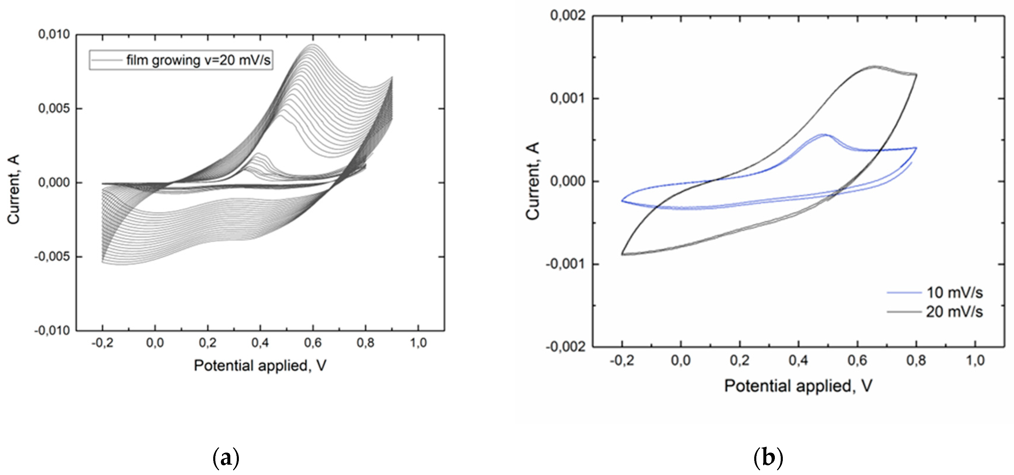
Cyclic voltammogram at scan rate 10 mV s
-1, shown in
Figure 1b, reveals the transition of polyaniline from non-conductive leucoemeraldine form to conductive emeraldine salt formed at 0.45-0.5V and the opposite reaction at 0V. The position and height of the cathode peak strongly depend on the scan rate: as it increases, the peak shifts to the right and becomes poorly defined [
25]. During electropolymerization, an increase in oxidation/reduction peaks is observed, due to growth of the polymer film (
Figure 1a).
This transition is the basis of the working principle of memristive devices. We namely utilize the manifold of intermediate states between pure leucoemeraldine and pure emeraldine salt, since the overall conductivity differs for different ratios of leucoemeraldine and emeraldine salt chains.
The fraction of reduced and oxidated segments in a polyaniline chain could be driven by appropriated external stimuli and this allows to have the continuum of resistive states in Polyaniline based memrisitve devices in which conductivity values from 10
-4 to 30 Sm/cm are obtained. This suggests that the speed of the front propagation is directly dependent on the external potential that feed the OMD, since even small flow of electrons or holes after overcoming the energetic barriers is enough to change red-ox states of polymer chain segments from one red-ox state to the other. This is actually the mechanism behind the propagation of red-ox front along the PAni film. Stable repetitive cyclic voltammograms (
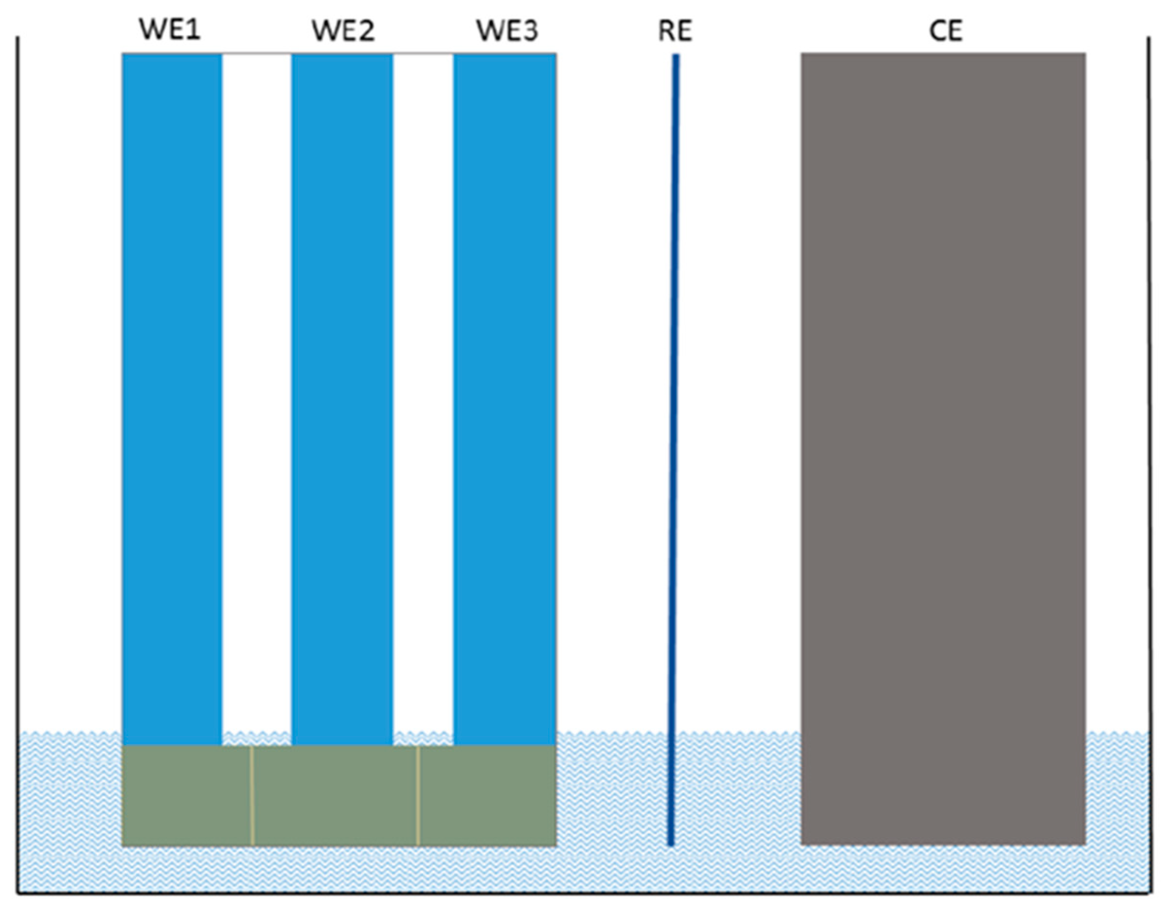
Figure 1b) were obtained for PAni film on the surface of the cell presented in
Figure 8. The peaks corresponding to the transition between leucoemeraldine and emeraldine states are clearly resolved. The anodic peak is shifted to higher potentials and the cathodic peak is shifted to lower potential values relative to their usual positions [
26] due to the high thickness of the film as well as high resistance of thin chromium electrodes.
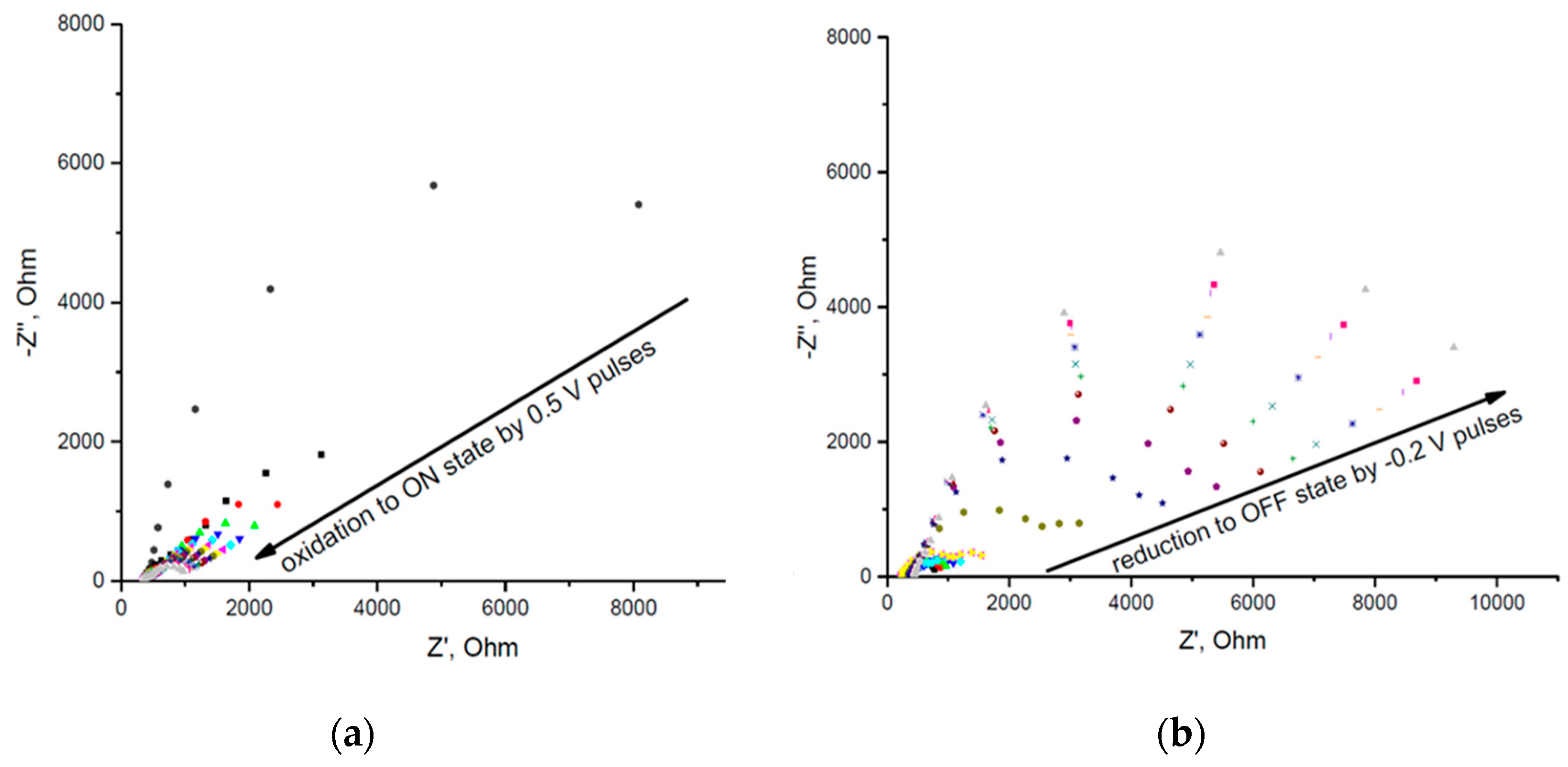
According to CV data described above pulses of 0.5 V (vs. Ag/AgCl RE) were used in order to switch the film into the conducting state. Pulses of -0.2 V (vs. Ag/AgCl RE) were used in order to reduce the film back to the non-conducting state. The dynamics of the impedance change after the application of consecutive voltage pulses is shown in
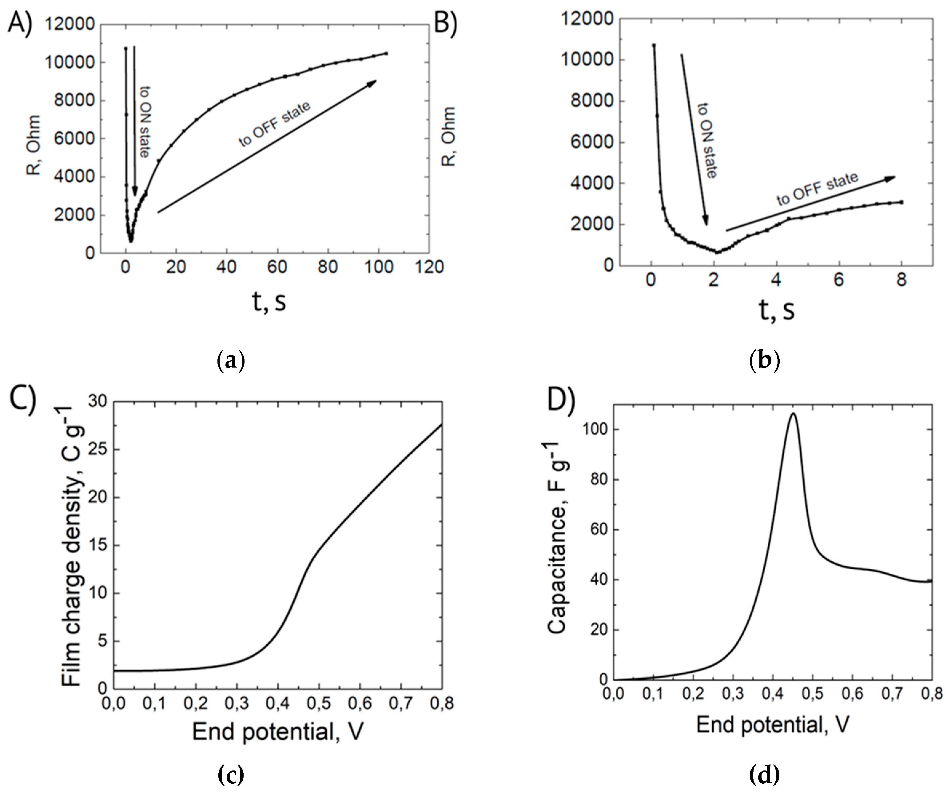
Figure 2. The impedance data were used to determine the resistance of PAni film. This was done by fitting the spectra with the semicircles (corresponding to Randles equivalent circuit) using built-in function in Nova 1.11 software. The calculated resistances vs. net time of voltage pulse application are presented in
Figure 3. The duration of anodic 0.5 V pulses was 100 ms. The initial duration of anodic -0.2 V pulses was the same (100 ms). Since the reduction back to off state was slow after 60 anodic pulses their duration was increased to 5 s. This allowed to obtain the dynamics of film resistance change with reasonable time resolution.
As one can see in
Figure 3 switching to the conducting ON state is relatively fast (it takes ~1 s) while switching back to a non-conductive OFF state is almost two orders of magnitude slower (it takes about 100 s). This temporal dependency of the process is directly correlated to the results already discussed for the PAni Cyclic Voltammetry. Observing the CV in
Figure 1, anodic and cathodic peaks have different shapes that are an efficient representations of the fractions of polymeric chains that are reacting. 0.5V corresponds to the maximum of current density of a narrow and defined cathode peak suggesting an intrinsically faster rate of reaction. The anodic peak in
Figure 1 instead is broader and less intense suggesting that the application of -0.2V would results in a slower reaction.
One may propose the following explanation of this effect. The reduction starts from the part of the film that is in contact with chromium layer. This results in a dramatic increase of the resistance of this part of the film which slows down the transport of electrons to the other parts, especially to the part which is located above the clearance between the electrodes. Therefore, the reduction speed should be limited by the rate of electron transport which is not the case for propagation of oxidation front.
The dependence of PANi film resistance on the duration of switching voltage signal has been measured, Strong difference between the dynamics of switching to conducting and non-conducting states in PANi films is observed.
It’s worth noticing that switching times can be significantly reduced by decreasing resistance and capacitance of the device. This can be done by switching from in-plane to through plane configuration of the prototype. This will decrease the resistance of PAni layer and a double layer capacitance of the interface between the phases with ionic and electronic conductivity.
Also, thicker metal film should be used as a support for PAni layer. 60-70 nm chromium layer has relatively high resistance which complicates the formation of uniform PAni film on the surface of the electrode and results in increased switching voltages due to current drop after supplying the volage.
Based on the dependence of film charge density on end potential, the change in film capacitance upon transition from non-conductive to conductive form at 0.45-0.5V was investigated (
Figure 3c,d). Slope changing on step coulogram, shown on
Figure 3c, corresponds to the transition between different PAni red-ox states [
27]. The capacitance plot as well as the magnitude of the capacitance peak agree in order of magnitude with the literature data (e.g., the maximum capacitance of 35 nm PAni film after converting per unit mass, correspondingly [
27,
28]).
The anomalous capacitance in the area of metal-insulator transition is due to extended interface between conducting and non-conducting phases.
The Chromium electrodes did not take part in electrochemistry reactions, as one can see from CVs of the films on Cr, reasonable explanation is that Chromium has thin oxide layer, which prohibits participation in electrochemical reactions.
3.2. Langmuir-Blodgett Films
For practical uses, it’s tremendously important to have a clear idea of the voltage distribution in the PAni channel during the standard operation of switching. This information is not only crucial for the designing of circuits and networks, but also for the correct application of the electrical field in the device in order to avoid overoxidation of the conductive polymer.
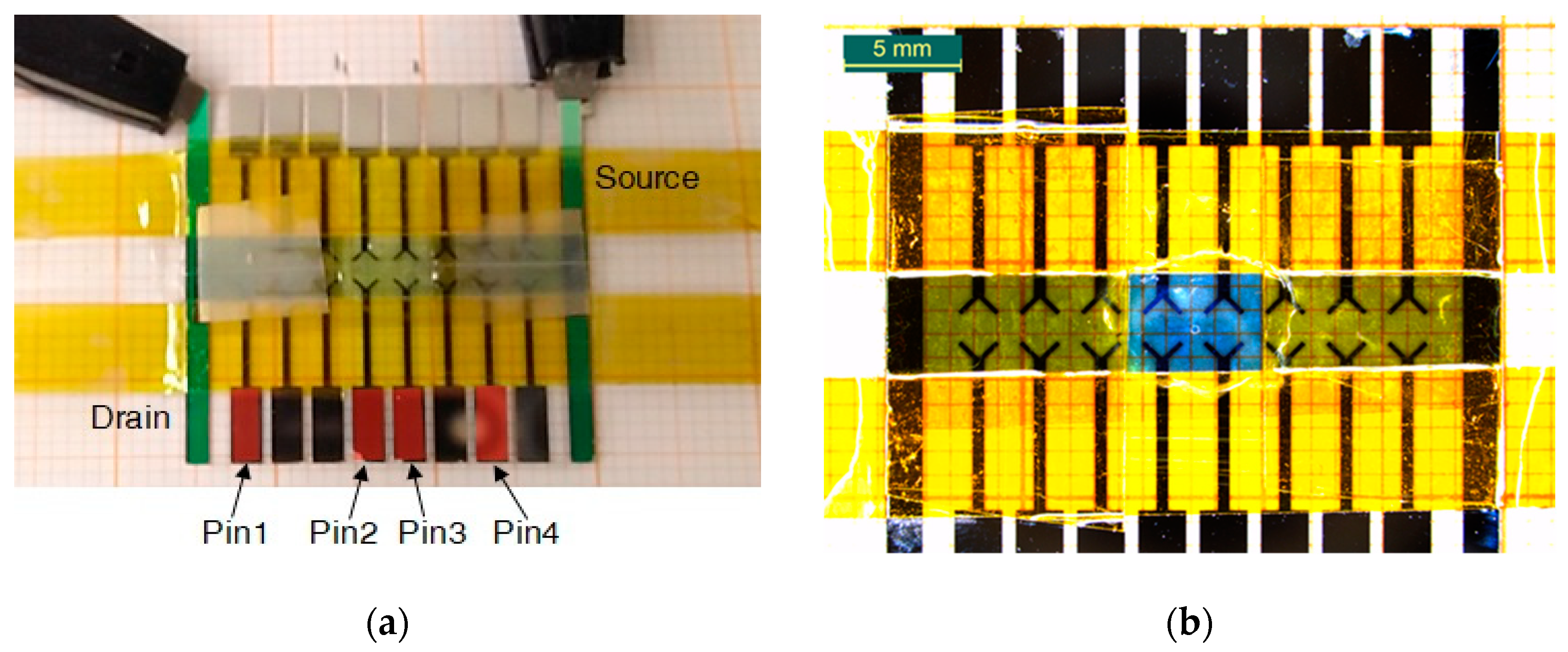
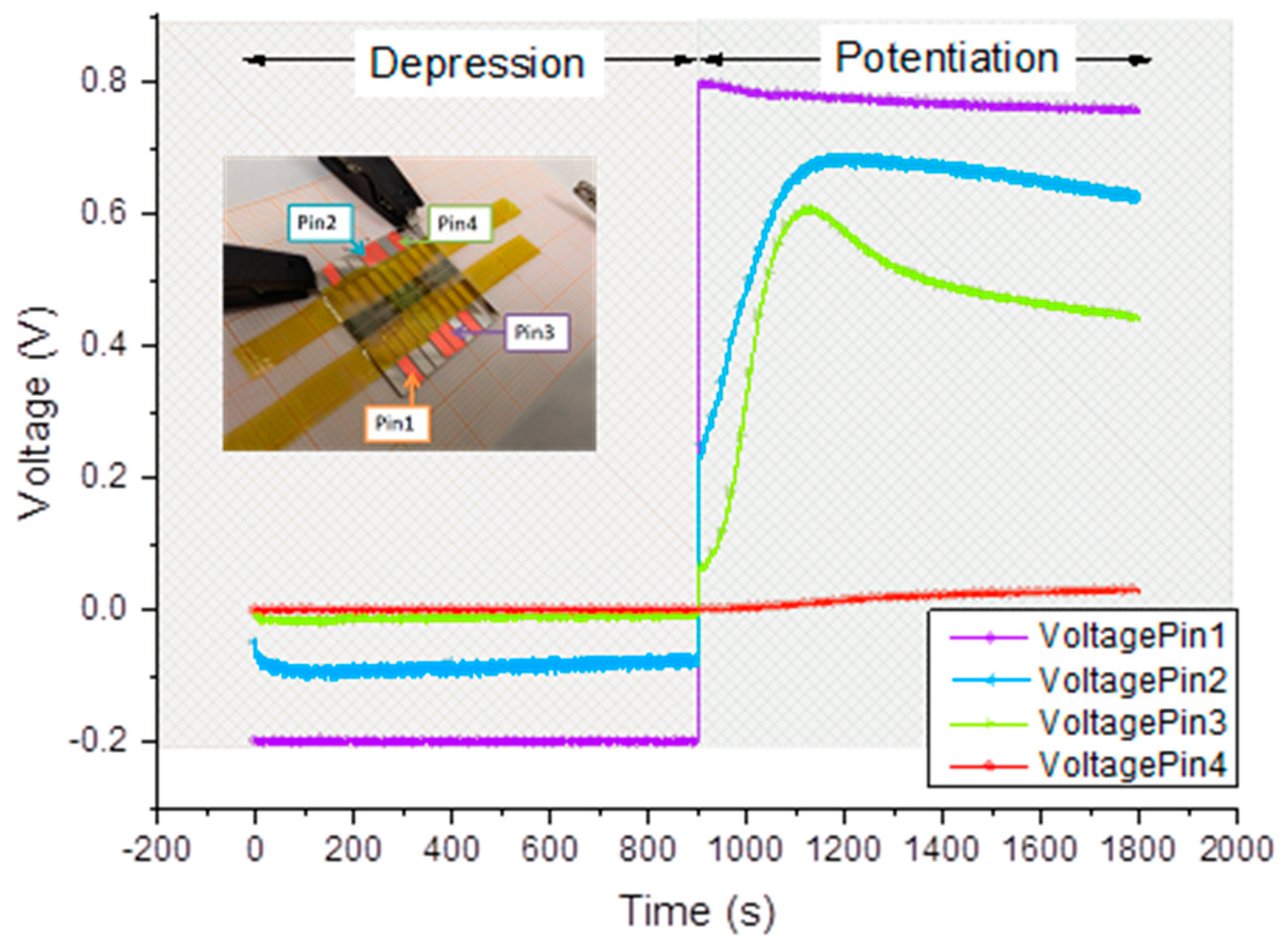
Voltage temporal variations acquired in 4 different points (Pin1-4) are reported in
Figure 7. Pin 1 ( purple curve) and Pin 4 ( red curve) are voltages acquired closer to the high voltage electrode (drain) and the ground potential, respectively. From the
Figure 7 one can see the propagation of the front as the voltage signal appearing on corresponding electrodes. The speed of front evolution was calculated, basing on potential evolution on electrodes (pin 2 and pin 3).
As it can be seen from
Figure 7, their readings are practically equal to preset values imposed by the SMUs, meaning that a negligible voltage drop occurred between them and the outer electrodes. This effect is rather comprehensible if considering that their readings belong to parts of the PAni channel not involved in the switching mechanism, whose conductivity must remain stable during operations. In Pin 1 curve, we can appreciate a gentle decrement ( symmetric to the increment of Pin4) that is the result of the conductivity variation during the application of 0.8V.
Pin 2 and 3 are contacts positioned in the active zone in which all redox reactions take place. In fact, profiles of the voltage variations of these latter are significantly different from the ones previously described. During the application of negative bias, Pin 2 shows a voltage value corresponding to the half of the applied bias while Pin 3 is practically grounded. This means that an important voltage drop occurs between Pin 2 and Pin 3, thus in the center of the active zone. It’s worth noticing that all four Pins have a rather constant voltage values while biased with a negative voltage. Just Pin 2 experimented a gentle variation of its potential at the beginning of the measurement suggesting the presence of a very fast reduction process. This means that films obtained with LS method, have a faster reduction process respect to the electropolymerized ones. This could be due to the different samples’ thickness and also to the different geometry used for the two experiments. During the potentiation procedure, the temporal evolution of Pin2 and pin 3 readings shows a marked increment, in totally agreement with what reported in [
29]. This effect is the direct demonstration of the variation of the resistivity of the PAni in the active zone as a result of the oxidation process. The speed of front propagation was calculated based on the evolution of potentials on Pins 2 and 3 by calculating the slopes of the curves (derivative of voltage evolution).
The experiment with Langmuir-Blodgett film showed steep and non-linear increase in the speed of front propagation, depending on the polyaniline film thickness. This is possibly due to shorter paths of anions, which should be moved in or moved out from the polyaniline film, at the moment of reduction or oxidation at the front interface, as is known from theoretical studies [
12].
High speed of red-ox front propagation (200 micron/s) together with pseudo two-terminal type of memristor devices opens up the possibility to manufacture not only neural networks, but also ReRAM cells, based on a conductance change in PAni bridges. For the use as ReRAM the gap between gold electrode should be made as small as 20 nm To allow switching of PAni in microseconds range.In such case it is possible to have different discrete Red-Ox states transitions and fast switching between different red-ox levels of few polymer segments, bridged in the small gap between electrodes, similar to described in [
30].
3.3. Spikes Propagation in Lithographically Made Cells
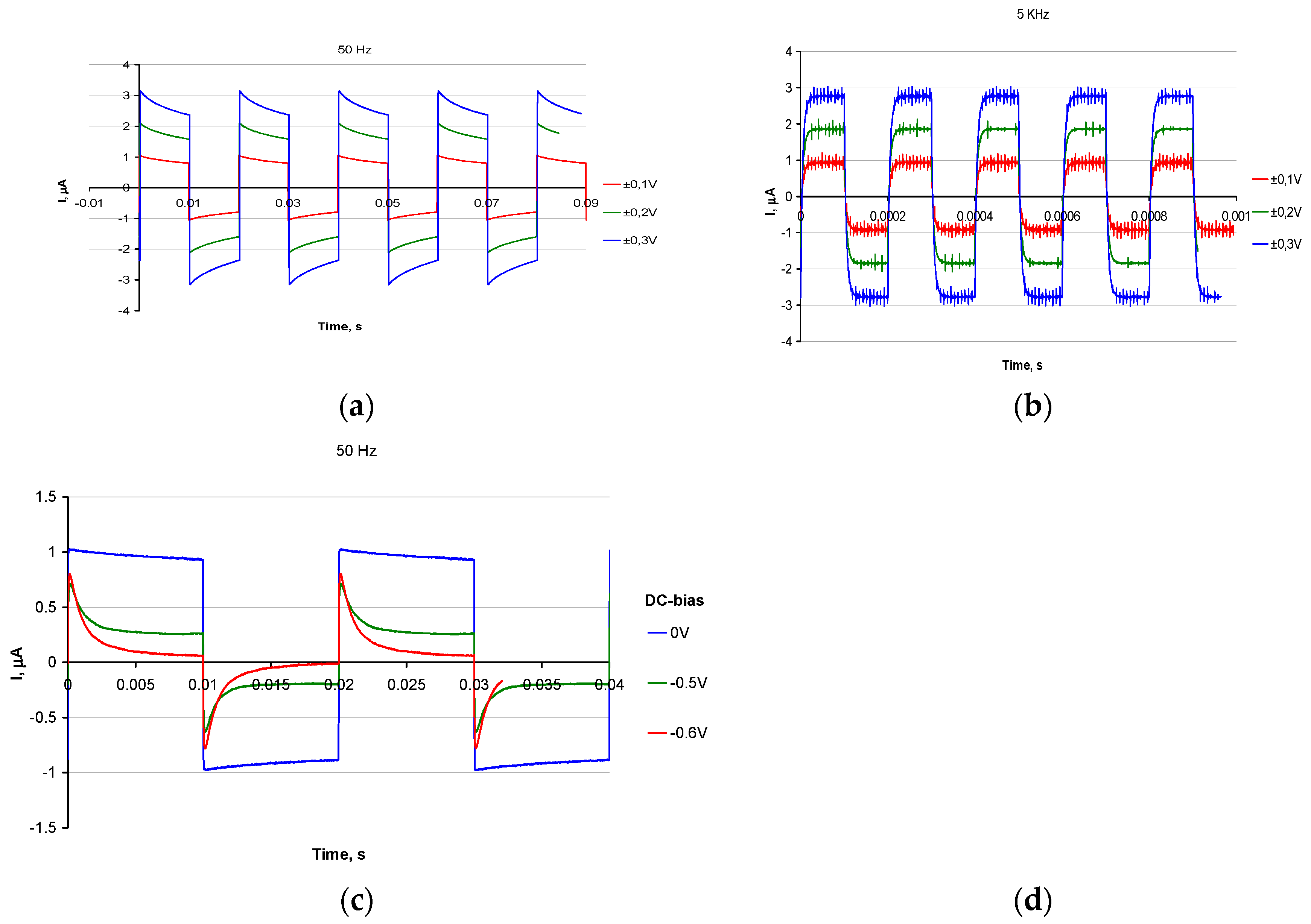
The propagation of spikes, studied for thin polyaniline bridges between gold electrodes showed two principally different operation modes of the memristor bridges: low frequency spikes (50 Hz,
Figure 6a,c) are accompanied by change of red-ox state of polyaniline, realized as processes with time constants of the order of few milliseconds. One can see, that curves at
Figure 6c are not symmetrical, which is due the change of conductance state after negative pulse is suppled. This is because the bias state on Figure 6c is close to leucoemeraldine – emeraldine salt transition. This is not the case for Figure 6a, which is far from transition and thus state of the film is not changed at voltage spikes.
It reflects the fact, that 50 Hz pulse is slow enough for the film to switch between conductive and non conducting state.
High frequency spikes (5 KHz,
Figure 6b), on the opposite, did not change the red-ox state of the polyaniline and were just manifestation of ohmic resistivity and capacitance of the polyaniline bridges in their current red-ox states. Actually, the RC formed by double layer capacitance and resistance, determined by states of PAni is responsible for chane of spike height which is thus proportional to the conductivity state in PAni film.
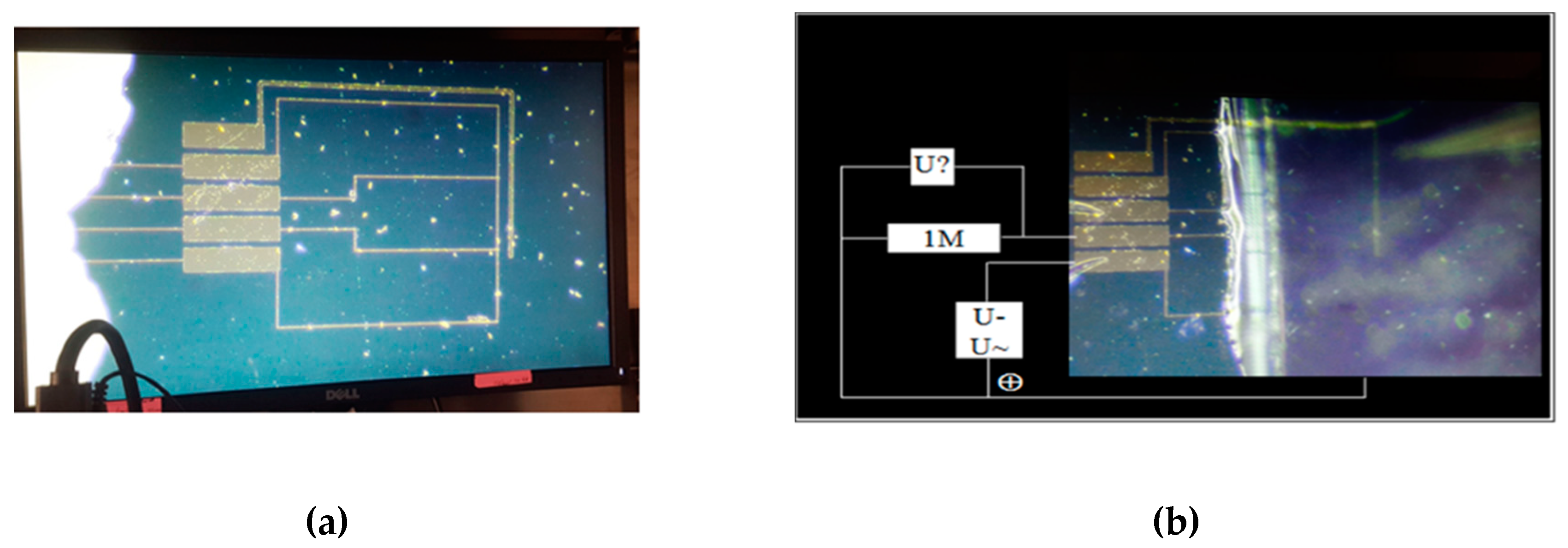
Simultaneous operation of different devices with voltages, fixed against the single counter-electrode was also possible
The existence of these two modes makes possible the mechanism of the supervised learning in the spiking neural networks, based on polyaniline memristive devices: while slow rate pulses can be used for training the spiking network, the short-pulse spikes can be used for network operation, not changing the resistances of the corresponding memristor bridges. If one excludes the transient part of the spikes before achieving the current plateau the reading duration time can be estimated to be as low as 30 s.
Introduction of constant bias against the counter electrode (Figure 6c) provides additional training opportunity. Adjusting the negative DC bias on PAni layer closer to the electrochemical potential of emeraldine/leucoemeraldine transition one can draw the memristor conductance closer to the switching threshold (Figure 6c). In this case small-amplitude spikes can significantly change the system state.
The red-ox front propagation was observed for some polymers, which change red-ox state including polyaniline. However, here we were able to detect for the first time the front propagation in PAni, measuring resistances and potentials directly in-cell, what allowed us to explain the mixed red-ox state front propagation in PAni samples , and our results provide the evidence to the fact, that red-ox front movement is fast enough to allow applications in spiking or rate-based neural networks or in ReRAM.
The red-ox front propagation in PAni has the similarity with signal propagation along biological synapses, with the soliton-like propagation of ion concentration change, accompanied with the change of red-ox state of polymer.
We also confirmed the idea, that making just one counter-electrode, bridged with the set of many two terminal memristive devices through a layer of polymer electrolyte allows to operate all the array of devices independently and simultaneously, using adequate potentials with respect to the reference electrode. This reflects the idea of making two-terminal memristive devices, where counter-electrode is the same for all elements in the circuit, allowing VLSI circuits, based on PAni bridges.
The speed of Red-Ox front propagation, equal to 200 microns/s, allows for samples, based on thin LB films, to make both spiking and rate-based neural networks, basing on two properties of polyaniline: it’s memristanse and red-ox front propagation.
While front propagation allows spikes to travel through polyaniline synapses, memristance allows memorizing the current mixed conductivity state . thus we showed, that gold pads and polyaninline memristive bridges can be used to manufacture Hebbian (linear) type neural networks
Accumulation of charges at gold or bi-metallic pad can possibly be used to make Leaky Integrate and Fire (LIF) type spiking neuron. In such way circuits, containing high density of neurons and synapses, possibly on flexible substrate, could be realized. It could also be possible, that sensing of ions concentration and influence of ions concentration on spikes propagation could be used for making interfaces between biological neurons and spiking polyaniline based circuits.
5. Conclusions
We observed the phenomenon of red-ox front propagation in polyaniline films, interfaced with liquid or solid polymer electrolyte. The speed of red-ox front propagation was found to be 3 microns in 1 second for thick (2 micron) films and 200 microns in 1 second for thin (50 nm) films, prepared using Langmuir-Blodgett technique.
The red-ox front changes the memristance of the film, which is frozen in new meta-stable state after the red-ox front propagation in the absence of electron exchange with electrodes. This opens the opportunity for making spike and rate-based neural networks, basing on polyaniline memristive synapses and metal pads.
We studied spikes propagation along memristive polyaniline synapses, bridged between gold electrodes and found two modes of spike propagation – fast signal, not changing the red-ox state of polyaniline and slow mode, when red-ox state of polyaniline is changed during spike propagation. The latter opens up the possibility to study spike time dependent plasticity (STDP) in our system and realize unsupervised learning, while the first opens the possibility to split training of the network and it’s operation allowing for supervised learning by means of backpropagation.
We also showed that only one counter-electrode, electrochemically bridged with polyaniline memristive devices is required to allow the simultaneous operation of large set of elements simultaneously, with potentials applied versus counter-electrode. This opens up the possibility to make the high density miniaturized arrays of pseudo-two terminal memristive devices, electrochemically connected through the layer of polymer electrolyte to only one counter-electrode.
The fast front propagation in thin PAni devices makes it possible to manufacture Resistive Random Access Memory cells with switching time in the range of microseconds
Thus, we have shown, that combination of metal contacts, bridged by polyaniline synapses, immersed in polymer electrolyte can be used for the development of rate-based and spiking neural networks.
