1. Introduction
Pyrolytic graphite exhibits strong diamagnetic properties and experiences a diamagnetic force when placed above a PM array. Despite the weak nature of this force, pyrolytic graphite can stably levitate on the PM array without an external energy input by overcoming gravity.
Extensive research has been conducted into the diamagnetism of pyrolytic graphite. Ominato [
1] predicted that the diamagnetism of graphene could be observed using the alignment of graphene flakes in a feasible range of magnetic fields. Niu [
2] discovered that pyrolytic graphite with an even positive polygon can be stably levitated on a permanent magnet array, while pyrolytic graphite with a regular odd polygon cannot levitate stably. Miriam [
3] demonstrated that the magnetic susceptibility of pyrolytic graphite decreases as temperature increases. Norio Inui [
4] calculated the potential energy of a square graphene sheet in vertical and horizontal states to a magnet. Kazunori [
5] explained the size and temperature dependence of fluctuations in the position and angle of a levitated graphene disk.
The advantage of diamagnetic levitation over other methods using magnetic forces is that diamagnetic objects can be stably levitated without active control at room temperature [
6]. Thus, pyrolytic graphite can be used in magnetic field detection, precise positioning, micromachinery [
7], [
8], nanorobots [
9] and susceptible sensors [
10] due to its advantages of passive and non-contact diamagnetic levitation. Cheng [
11] experimented on an energy harvester based on the diamagnetic levitation structure. Ding [
12] used pyrolytic graphite to fabricate rotors, suggesting potential applications of this mechanism in suspension bearings and micro-actuators. Masayuki [
13] used graphite, Nd-Fe-B permanent magnets and light to create an optical motion control system. Zhang [
14] studied a gas flowmeter using a diamagnetic levitation rotor made of pyrolytic graphite. Ali AD [
15] used pyrolytic graphite to design 3 control models that take hydrodynamic effects exerted on the microrobot into account. Hüseyin U [
16] proposed a novel micro-robotic manipulation technique with high precision (nanoscale) positioning capability, suitable for movement in an environment featuring diamagnetic levitation of liquid.
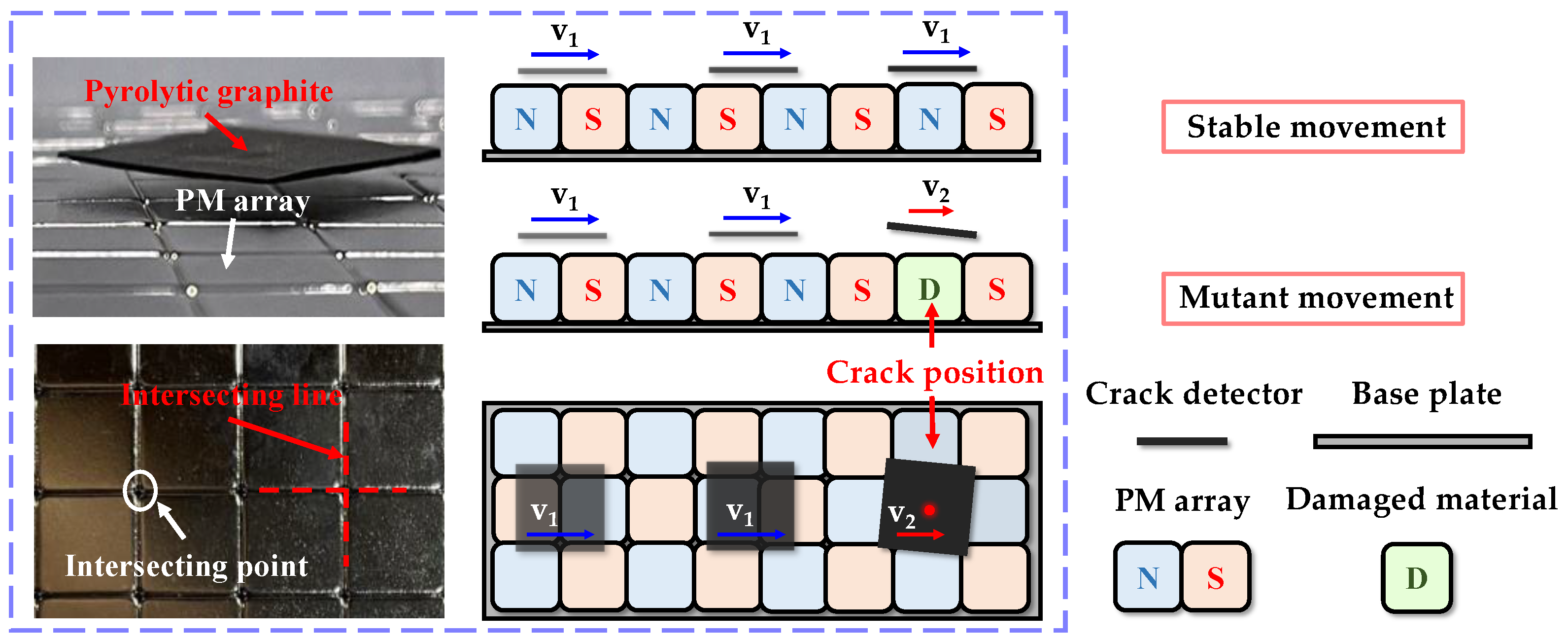
A stable magnetic field used for pyrolytic graphite is generated by a PM array, which is constructed using multiple small magnets (10×10×5mm
3) arranged in intersecting points and lines. When the pyrolytic graphite is levitated over the PM array, its diamagnetic force becomes equal and opposite to gravity. The pyrolytic graphite levitation technique can be applied to non-destructive testing for identifying cracks and defects in magnetic materials, as shown in
Figure 1. Occurrence of surface or internal damage or cracks in permanent magnets alters their magnetic field. The pyrolytic graphite generates an eddy current damping effect as it approaches the crack due to sudden alteration in the magnetic field, altering its in-plane motion state, thereby facilitating precise identification of the crack location. This method is valuable as it enables non-contact testing that minimizes the risk of damaging tested materials, improves test efficiency, and reduces overall costs.
Despite the numerous potentials offered by pyrolytic graphite magnetic levitation technology, its practical applications are restricted by the phenomenon of in-plane forces acting on in-plane motion. Previous studies have often regarded pyrolytic graphite as the substrate for magnetic levitation, and permanent magnets as the carrier for in-plane motion. Instead, in our research, permanent magnet arrays were used to provide a magnetic field environment for pyrolytic graphite magnetic levitation, while pyrolytic graphite was employed as the carrier of in-plane motion. This study aims to investigate the in-plane motion characteristics of the pyrolytic graphite plate, thereby determining the magnetic potential energy distribution generated and analyzing the levitation position, in-plane forces, and damping ratio during pyrolytic graphite in-plane motion, as well as the level of frictional force and friction coefficient during its rotational motion around a fixed axis.
2. Material and Methods
Earnshaw’s theorem states that charged objects cannot be maintained in a stable stationary equilibrium solely by the electrostatic interaction of the charges [
17]. The diamagnetism of pyrolytic graphite is caused by Landau diamagnetism, which is closely related to the unique Dirac cone band structure and Fermi level of graphite [
18]. When an external magnetic field is applied, low-energy electrons will migrate from the valence band to the conduction band. Electron mobility with high magnetic flux will generate a robust equivalent current and then create a reverse-induced magnetic field to resist changes in the external magnetic field. Since the direction of the equivalent magnetic moment is different from the outside, pyrolytic graphite exhibits diamagnetism [
19].
The magnetic force
F is [
20]:
The force density
f can be expressed as:
For the diamagnetic materials:
where
H is the magnetic field strength,
B is the magnetic flux density,
M is the magnetization,
χ is the magnetic susceptibility,
μ0 is the vacuum permeability,
μ0 = 4π×10
-7.
The final expression for the force density
f is:
where
χx is the magnetic susceptibility along the X-direction,
χy is the magnetic susceptibility along the Y-direction,
χz is the magnetic susceptibility along the Z-direction.
Simon and Geim have determined the value of
χ for PG, which is given by [
21]:
The magnetic force with the entire volume can be expressed as:
Force along the y-direction for the entire volume is represented as [
9]
3. Location characteristics
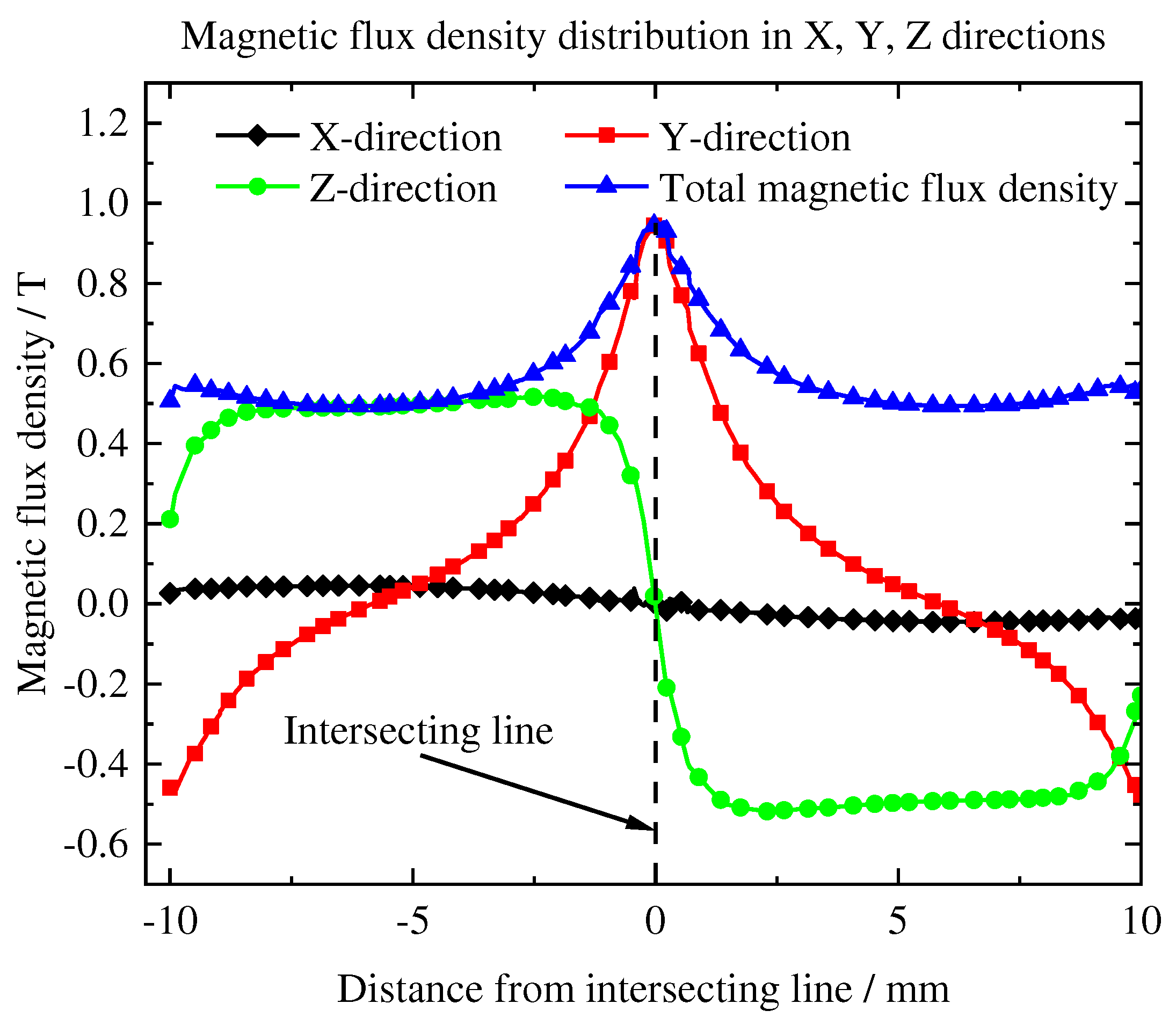
To begin with, we evaluated the magnetic flux density distribution in X, Y, and Z directions above the PM array, as shown in
Figure 2. Where the total magnetic flux density is
. The magnetic flux density is mainly distributed at the intersecting line of the PM array. The further is away from the intersecting line of the PM array, the lower is magnetic flux density.
Then we investigated the potential energy distribution above the PM array to determine the position of stable levitation of pyrolytic graphite. The total potential energy above the PM array can be calculated using the following equation [
22]:
When the pyrolytic graphite is stably levitated above the PM array, it should be located at the lowest point of potential energy in this region [
23]. If the pyrolytic graphite position cannot reach the lowest point of local potential energy, it cannot levitate stably, resulting in translation, vibration, rotation, and other motions. The diamagnetic potential on pyrolytic graphite can be expressed as follows [
22]:
where
V is the volume of graphite.
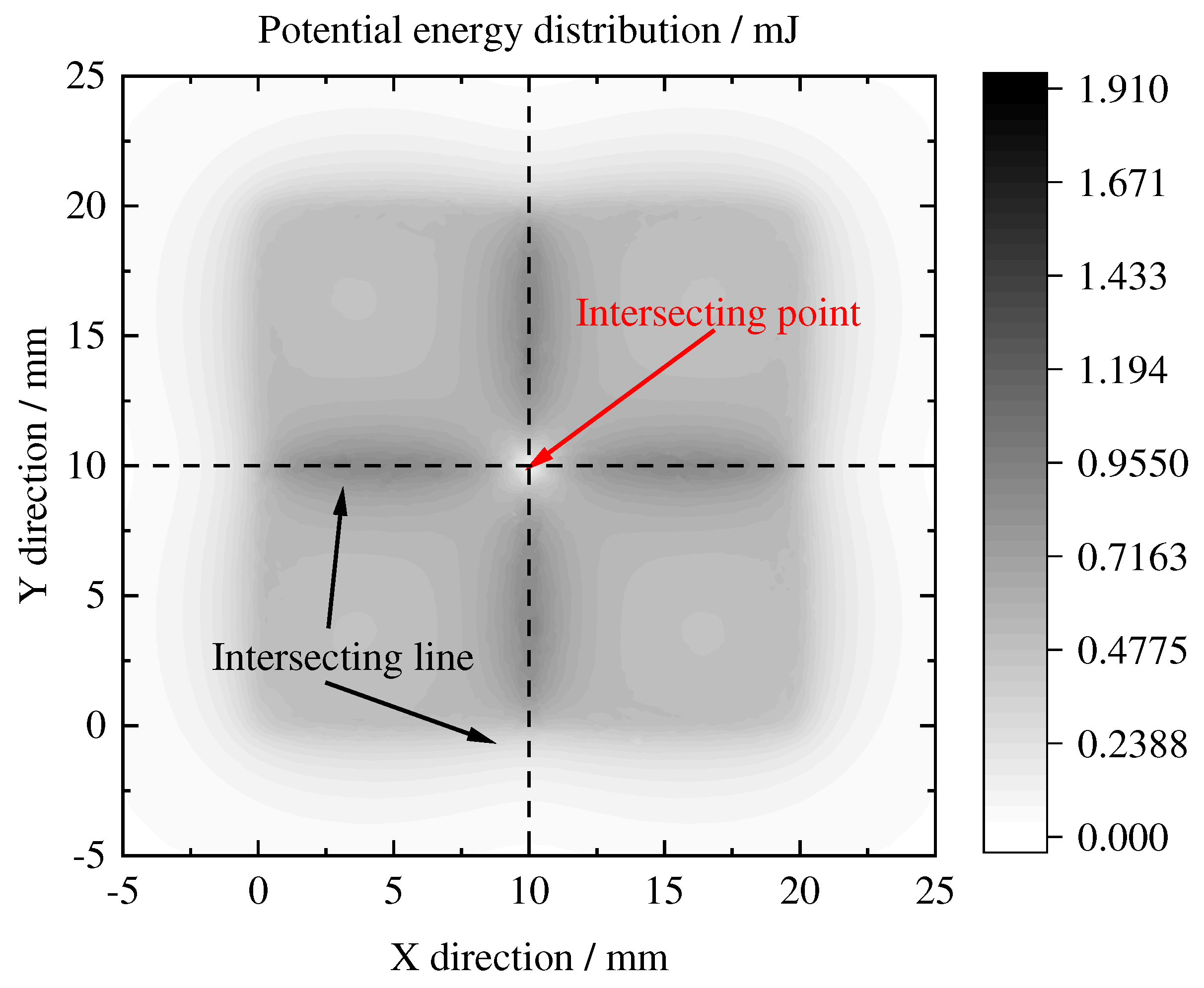
The distribution of potential energy above the PM array can be obtained, as depicted in
Figure 3. It is evident that the potential energy reaches its maximum at the intersecting line of the PM arrays and minimum at the intersecting point. This observation suggests that the centroid of pyrolytic graphite will be levitated in a stable manner above the intersection point of the PM arrays.
4. In-plane motion characteristics
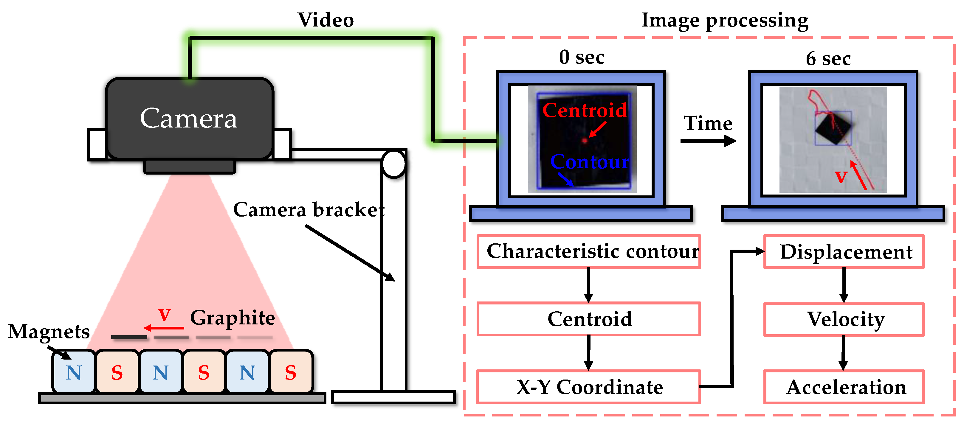
The experimental system for in-plane motion is shown in
Figure 4. Initially, a gentle air flow is employed to drive the pyrolytic graphite. Simultaneously, a camera above the PM array transmits real-time video of the pyrolytic graphite's movements to PC. Subsequently, the PC is utilized to identify the contour (blue rectangle in
Figure 4) and centroid (red dot in
Figure 4) of the pyrolytic graphite from the captured video footage. The coordinate displacement of the centroid in each frame can be determined, which can then be used to calculate the centroid's velocity, acceleration, and other parameters associated with its in-plane motion using formula (12) and formula (13).
where
V (k) is the velocity of centroid in frame
K,
Cent (k, 1) and
Cent (k-1,1) are the X coordinates corresponding to the centroid of pyrolytic graphite in frames K and K-1, respectively,
Cent (k, 2) and
Cent (k-1, 2) are the Y coordinate corresponding to the centroid of pyrolytic graphite in frames
K and
K-1, respectively,
∆t is the time interval,
D is the actual side length of pyrolytic graphite,
DIAM is the pixel length corresponding to the calibration line,
a (k) is the acceleration of pyrolytic graphite motion in frame
K. These motion parameters can efficiently calculate the in-plane force acting on pyrolytic graphite.
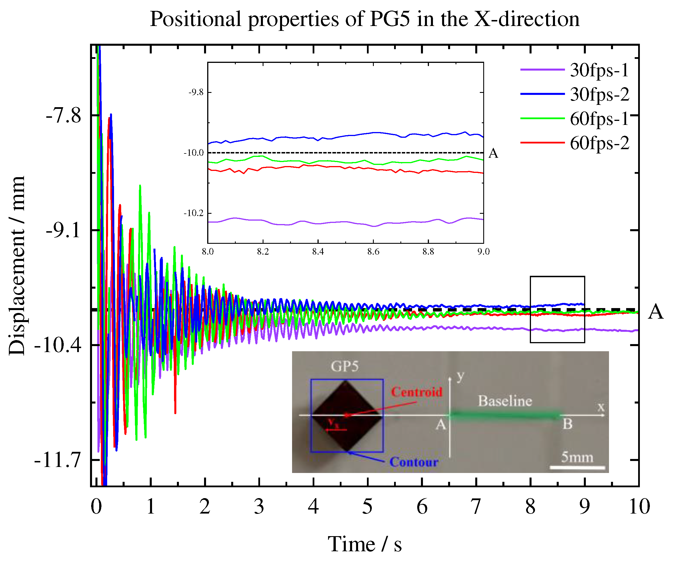
The positional characteristics of pyrolytic graphite during in-plane oscillation were also examined. In this experiment, we used pyrolytic graphite with dimensions of 5×5×0.5mm
3 (PG5). Firstly, a baseline was drawn on the PM array, and its two endpoints were labeled as A and B. To eliminate the impact of the video frame rate on PG5 parameters, we released PG5 at the same location and captured its centroid motion parameters using two different video frame rates (30fps & 60fps). Due to the in-plane force, the oscillation displacement of the pyrolytic graphite gradually decreased and ultimately stabilized at a specific point. The displacement between the centroid of the pyrolytic graphite and point A in the X-direction was determined, as depicted in
Figure 5. The analysis revealed that the centroid of the pyrolytic graphite will levitate at the intersection point of the PM array.
5. Damping characteristics
5.1. In plane motion
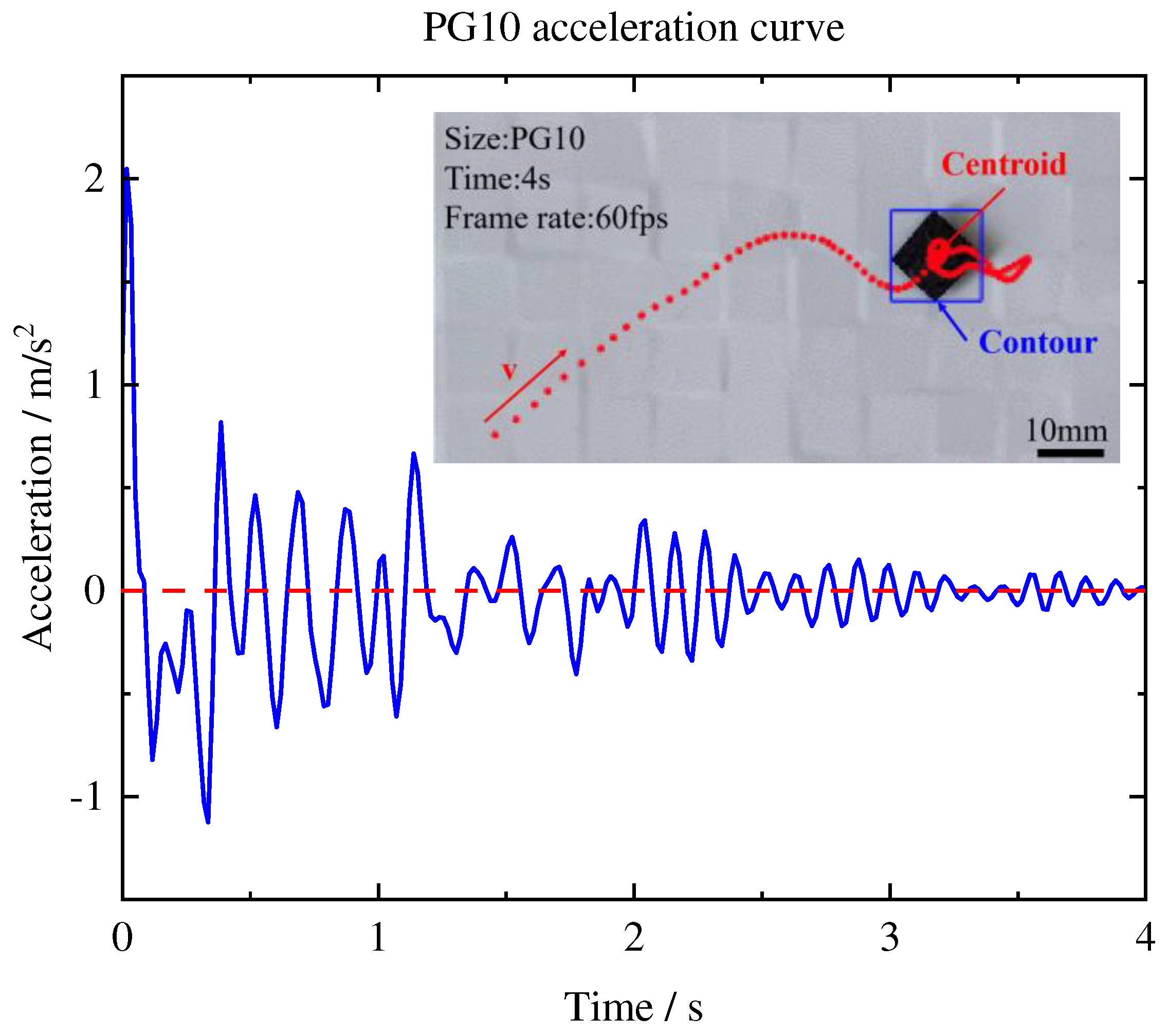
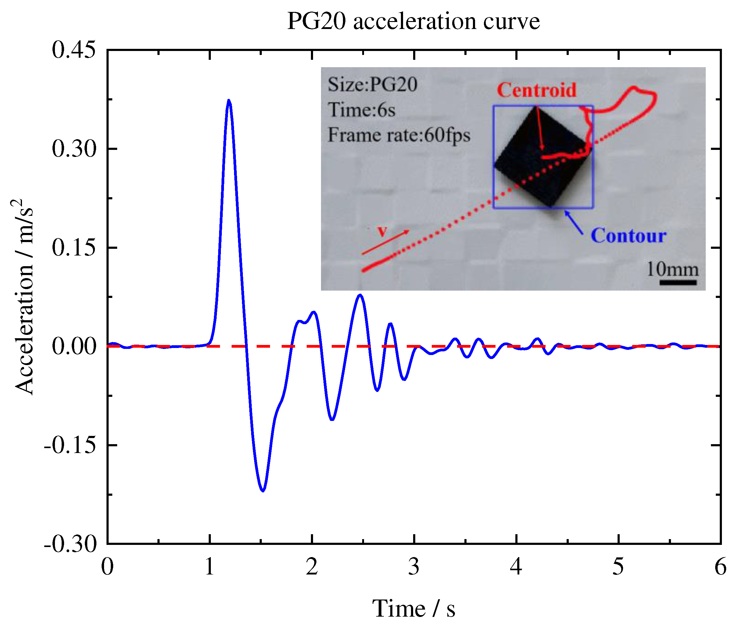
In this experiment, PG10 and PG20 were used to investigate the in-plane force. The outcomes from
Figure 6 and
Figure 7 indicated that PG10 demonstrated a greater acceleration and stabilization rate compared to PG20.The in-plane force
F can be calculated by:
where
ρ = 2.2 g/cm
3 is the density of PG;
m and
n are the length and width of PG, respectively;
h is the thickness of PG;
a is the acceleration of PG. The in-plane force on PG10 and PG20 is about 61.4μN and 28.2μN, respectively. This means that the in-plane force is at the micro-newton level. Interestingly, PG10 reaches stability faster and receives a greater in-plane force than PG20.
The smaller ratio of the size of GP10 to the permanent magnet compared to GP20 leads to more uniform in-plane forces experienced by PG20. Accordingly, we propose that the duration and magnitude of in-plane force stability of pyrolytic graphite are dependent on the size ratio of PG to the PM array. Specifically, larger-sized pyrolytic graphite experiences diminished in-plane forces and can achieve extended periods of stable levitation, ultimately resulting in smoother and more stable motion. As the size of pyrolytic graphite increases, the in-plane force is distributed over a larger area, leading to reduced forces on unit area and greater stability.
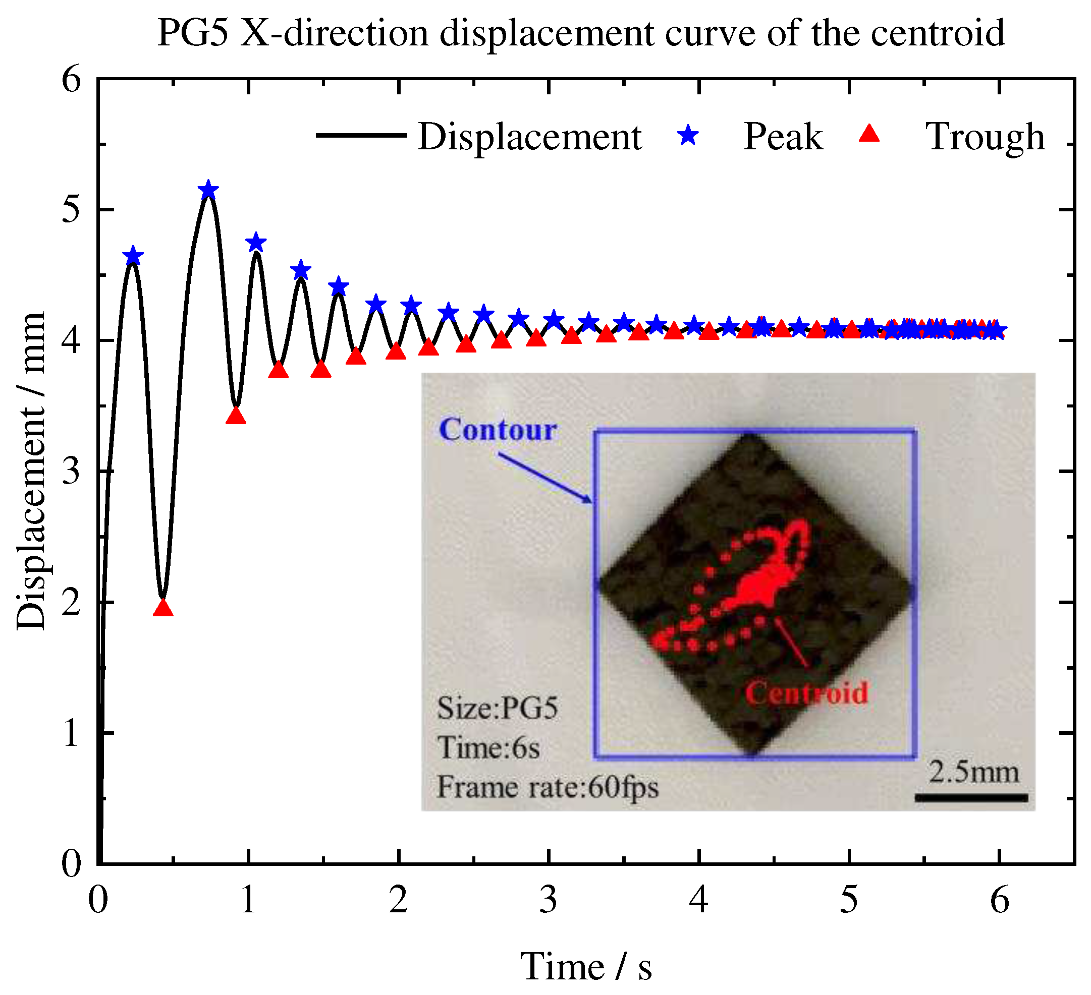
We also examined the damping ratio of pyrolytic graphite during in-plane oscillation. The in-plane force causes a gradual reduction in the oscillation displacement of pyrolytic graphite. PG5 and PG10 were employed to investigate this phenomenon. The centroid displacement curves in the X-direction were obtained by releasing the pyrolytic graphite at the same point.
Figure 8 display the X-direction displacement curves for PG5.
The damping ratio ξ is calculated by [
24]:
The values X(A) and X(B) from the centroid displacement curve represent the peak and trough values, respectively, with A and B corresponding to motion times. The damping ratios for PG5 and PG10 were then calculated and are presented in
Table 1. The damping ratio during in-plane oscillation was found to be between 0.1-0.2. The damping ratio of PG5 was lower than that of PG10, indicating an increase in damping ratio with increasing PG size. We believe that the increase in damping ratio with size variation may be related to the increase in surface area and mass, leading to more significant energy dissipation. Furthermore, smaller pyrolytic graphite has a lower moment of inertia and can move more quickly. This suggests that smaller pyrolytic graphite would be suitable for precise positioning of micromachines.
5.2. Fixed axis rotation
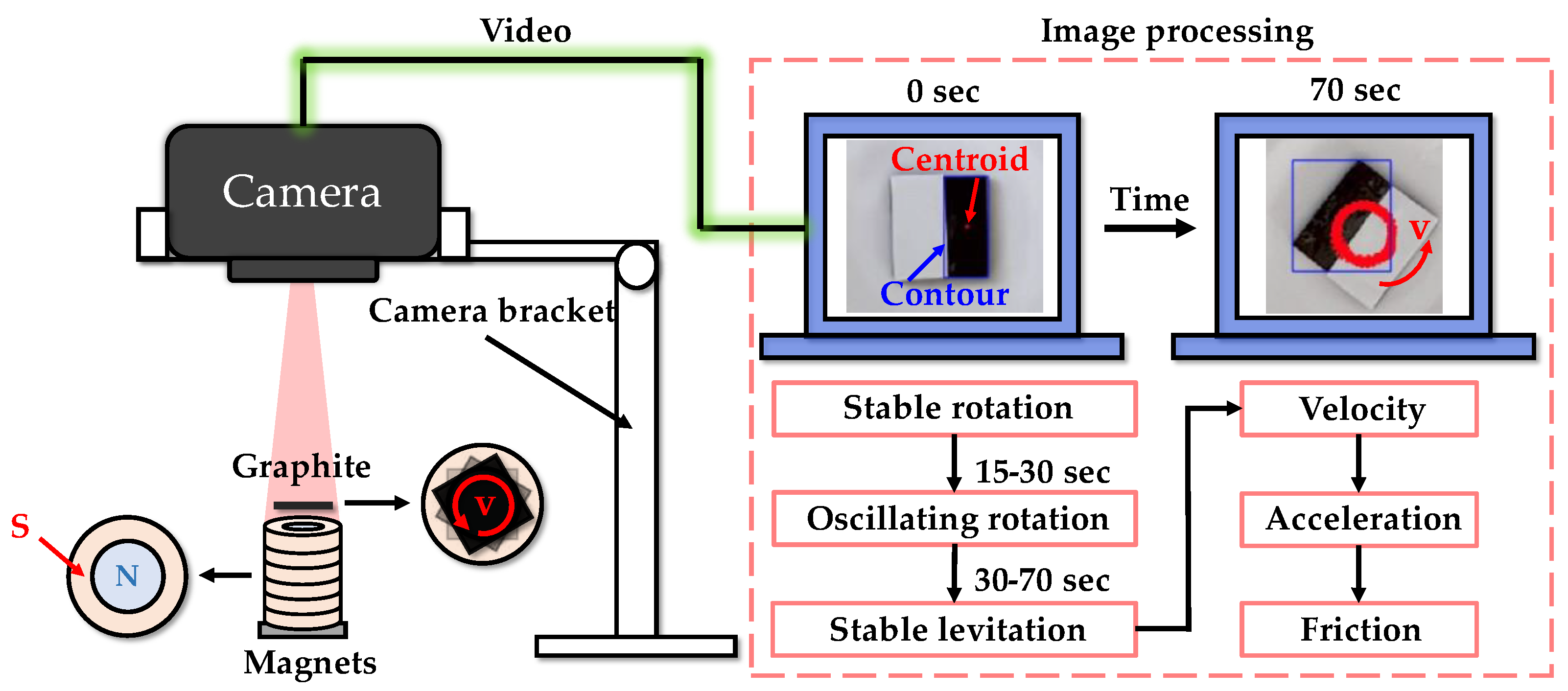
During the process of magnetic levitation, pyrolytic graphite undergoes not only in-plane translational motion, but also in-plane fixed axis rotational motion. When pyrolytic graphite undergoes fixed axis rotation, the rotational friction force hinders its motion. Therefore, this part investigates the friction force and coefficient of PG10 during fixed axis rotation using a polarity-crossing annular PM array and white sticker to cover half of the PG10's surface. The experimental setup for fixed axis rotation is shown in
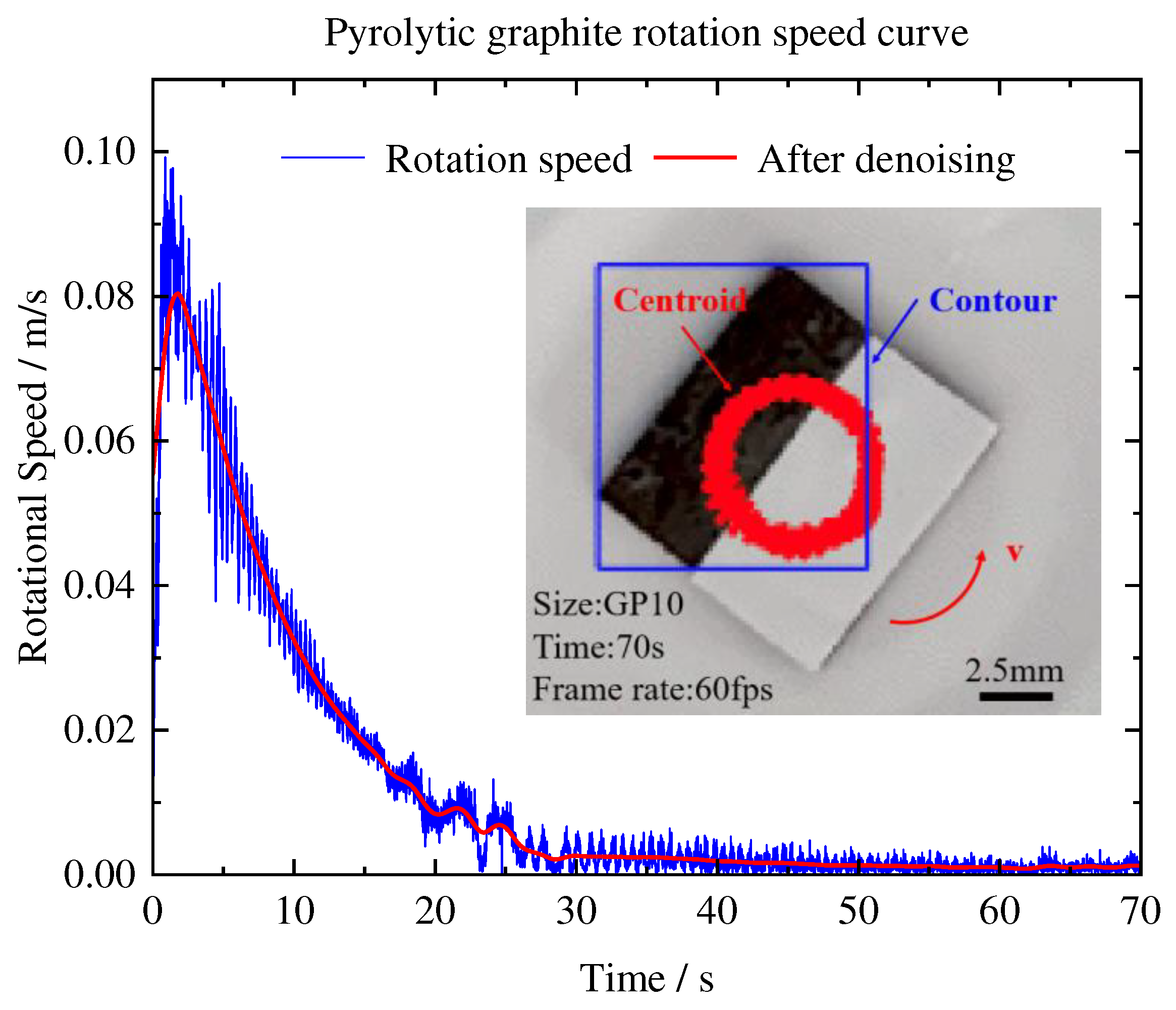
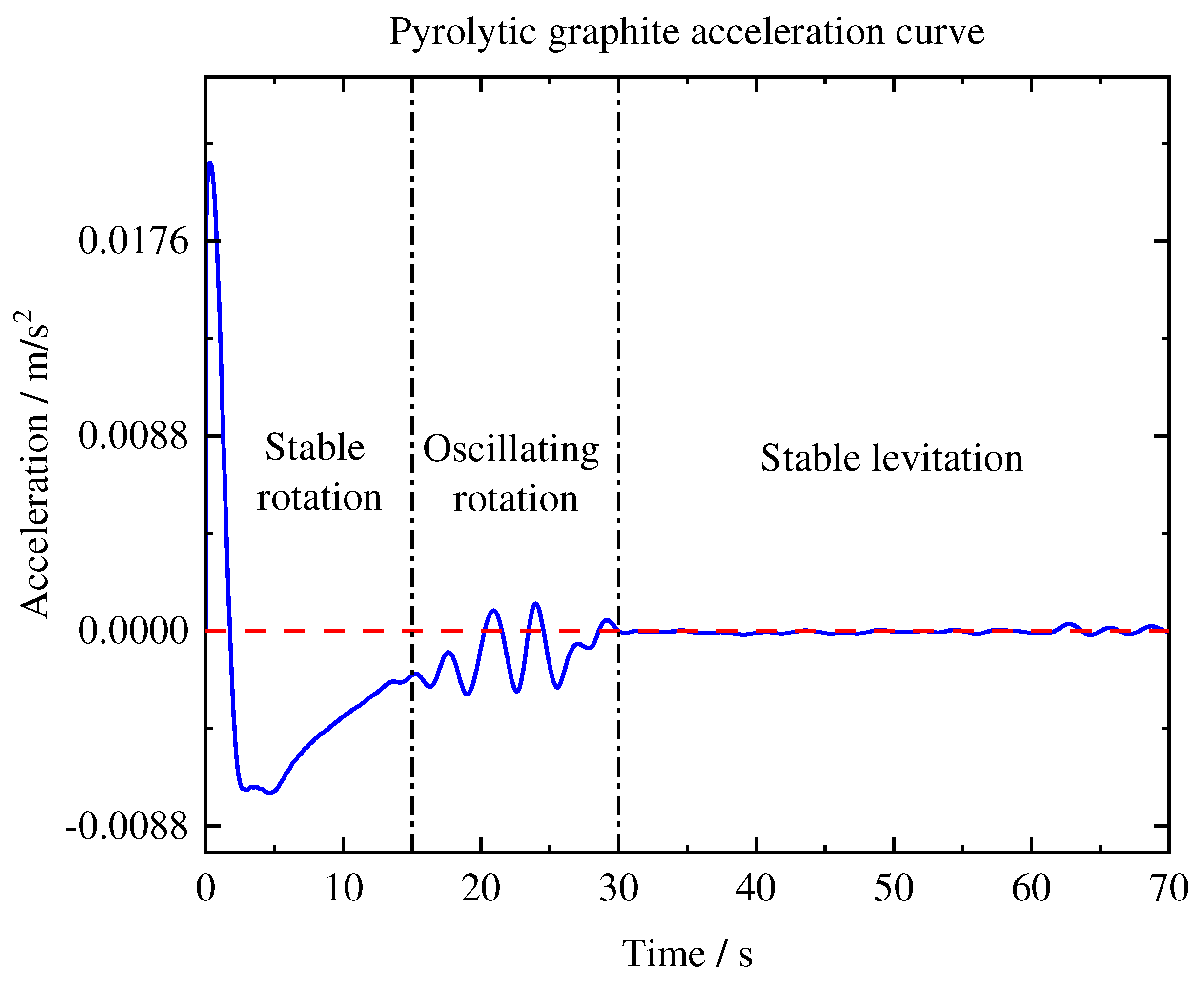
Figure 9, where rotation speed and acceleration were obtained by scale conversion, as represented in
Figure 10 and
Figure 11. To remove noise, it was necessary to filter the data of the fixed-axis rotation speed of graphite. The de-noised rotation speed is depicted by the red line in
Figure 10, while the blue line represents the original dataset.
As shown in
Figure 10, the stable rotation stage occurs for 0-15 seconds. Over time, the rotational speed gradually decreases, and the velocity and acceleration curves exhibit a relatively smooth trend. The oscillating rotation stage occurs during approximately 15-30 seconds, during which pyrolytic graphite exhibits an unstable rotation pattern characterized by oscillations rather than a stable cycle. After 30 seconds, the motion of pyrolytic graphite tends to stabilize, and PG10 eventually achieves stable levitation on the circular PM array.
The friction force and coefficient are calculated by:
Where Fμ is the friction of PG; μ is the coefficient of friction; m10 is the mass of PG10; g is the acceleration of gravity, g = 9.8 m/s2; aμ is the acceleration of PG10.
The calculation results indicate that the magnitude of the friction coefficient is 10
-3. When PG10 is in a stable rotation stage, the maximum frictional force is approximately 0.8μN. It can be seen from
Figure 11 that as the rotational speed decreases, the frictional force gradually decreases. We believe that the reason for this phenomenon may be related to the air resistance because a higher rotational speed of pyrolytic graphite means that air resistance consumes more power in unit time, which accelerates the rate of speed reduction. In addition, as previously mentioned, magnetic levitation technology has the advantage of being non-contact. In this experiment, only a momentary airflow was applied to the pyrolytic graphite. If a long-term and stable airflow can be obtained, pyrolytic graphite could be expected to become a gas bearing or a gas flow meter.
6. Discussion
This study investigated the in-plane forces acting on pyrolytic graphite. The results demonstrate that these forces impede its in-plane motion, and there are two primary sources of in-plane force: air resistance and eddy current damping. During the in-plane movement of pyrolytic graphite, air generates a frictional force that opposes the motion. Chen [
25] modeled eddy current damping and determined that it dominates dissipation in mm-sized pyrolytic graphite. Based on previous research and findings, we posit that the in-plane force is the macroscopic manifestation of the combined effects of air resistance and eddy current damping.
We expect to improve the stability of magnetic levitation of pyrolytic graphite, prolong the in-plane motion time, and ultimately enable the use of pyrolytic graphite for magnetic detection, precise positioning, and other micro-machines. For example, small-sized pyrolytic graphite can be used for fast and accurate positioning. In addition, the in-plane motion characteristics of pyrolytic graphite as a magnetic levitation material can also be applied in the field of magnetic sensors. For instance, this material can be used in high-precision magnetic sensors to achieve higher measurement accuracy and a wider measurement range.
Table 2 presents the potential applications of pyrolytic graphite using diamagnetic levitation technology at different size specifications. In summary, combining the characteristics of pyrolytic graphite as a magnetic levitation material with magnetic detection technology can bring about various applications, providing strong support for future scientific research and industrial applications.
7. Conclusions
This study investigated the diamagnetic levitation process of pyrolytic graphite on a permanent magnet array from various aspects and drew several important conclusions. Firstly, we found that the intersection points on the permanent magnet array had the lowest potential energy and validated the stable levitation of pyrolytic graphite on this point. Secondly, we discovered that the force exerted on pyrolytic graphite during in-plane motion was in the micro-newton level, and the damping ratio during oscillation was between 0.1 and 0.2. We believe that the magnitude of the in-plane force and the stable time of the pyrolytic graphite are related to the size ratio between it and the PM. With the increase of pyrolytic graphite size, the force acting on it will be distributed over a larger area, reducing the force on each individual point, and promoting the stability of its motion. During the fixed-axis rotation process, the friction coefficient and friction force decreased as the rotational speed decreased. The reason for this phenomenon may be related to the air resistance.
This research findings suggest that smaller-sized pyrolytic graphite can be used for magnetic detection, precise positioning, and other microdevices. Additionally, in the field of non-destructive material testing, the pyrolytic graphite diamagnetic levitation can also be used for detecting cracks and defects in magnetic materials. Further research is expected to be conducted to fully exploit the potential applications of pyrolytic graphite in the field of micromachines.
Author Contributions
Conceptualization, Wenjiang Yang, Runze Liu, Hongjun Xiang and; methodology, Runze Liu and Hongjun Xiang; software, Runze Liu and Peng Zhao; validation, Runze Liu and Hongjun Xiang; formal analysis, Wenjiang Yang and Runze Liu; investigation, Runze Liu and Juzhuang Yan; resources, Wenjiang Yang, Runze Liu and Hongjun Xiang; data curation, Runze Liu and Peng Zhao; writing—original draft preparation, Runze Liu; writing—review and editing, Runze Liu and Wenjiang Yang; visualization,Runze Liu and Fuwen Deng; supervision, Wenjiang Yang; project administration, Wenjiang Yang; funding acquisition, Wenjiang Yang. All authors have read and agreed to the published version of the manuscript.
Funding
This research was funded by the National Natural Science Foundation of China, grant number 11772025.
Institutional Review Board Statement
Not applicable.
Informed Consent Statement
Not applicable.
Data Availability Statement
Not applicable.
Conflicts of Interest
The authors declare no conflict of interest.
References
- Ominato Y, Koshino M. Orbital magnetism of graphene flakes. Physical Review B 2013, 87,115433.
- Chao Niu. et al. Graphene levitation and orientation control using a magnetic field. JOURNAL OF APPLIED PHYSICS 2018, 123,044302.
- Miriam Ewall-Wice. et al. Optomechanical Actuation of Diamagnetically Levitated Pyrolytic Graphite. IEEE TRANSACTIONS ON MAGNETICS 2019, 55,2501506.
- Inui N. Numerical study on stability of diamagnetic levitation of a single-layer graphene sheet. Journal of Applied Physics 2021, 130,183905.
- Inui N, Maebuchi K. Dynamic and fluctuation properties of a graphene disk levitated by a diamagnetic force in air. Journal of Physics D: Applied Physics 2022, 55,285002.
- Semenenko B, Esquinazi P D. Diamagnetism of bulk graphite revised. Magnetochemistry 2018, 4,52.
- Su Y F. et al. Micromachined Graphite Rotor Based on Diamagnetic Levitation. IEEE ELECTRON DEVICE LETTERS 2015, 36,393-395.
- Su Y, Ye Z, Xiao Z, et al. Analytical and experimental study of micromachined graphite rotor based on diamagnetic levitation,10th IEEE International Conference on Nano/Micro Engineered and Molecular Systems. IEEE, 2015.
- Lin Feng. et al. Microrobot with passive diamagnetic levitation for microparticle manipulations. JOURNAL OF APPLIED PHYSICS 2017, 122,243901.
- Chen X F, Kothari N, Steeneken PG. et al. Diamagnetically levitating resonant weighing scale. SENSORS AND ACTUATORS A-PHYSICAL 2021,330,112842.
- Cheng S H, Li X, et al. Levitation Characteristics Analysis of a Diamagnetically Stabilized Levitation Structure. Micromachines, 2021, 12,982.
- Ding J Q, Zhang K, Zhang Z Y, et al. Theoretical and Simulation Analysis of Micro - Machined Graphite Rotor Levitated Above Permanent Structure . CHINESE JOURNAL OF SENSORS AND ACTUATORS 2018,2,180-184.
- Masayuki Kobayashi. et al. Optical Motion Control of Maglev Graphite. American Chemical Society 2012, 134,20593−20596.
- Kun Zhang. et al. Design and Analysis of A Gas Flowmeter Using Diamagnetic Levitation. IEEE Sensors Journal 2018, 18,6978-6985.
- Ali Anil Demircali. et al. Stabilization of Microrobot Motion Characteristics in Liquid Media. Micromachines, 2018, 9, 363.
- Hüseyin U. et al. Micro-UFO (Untethered Floating Object): A Highly Accurate Microrobot Manipulation Technique. Micromachines, 2018, 9, 126.
- EARNSHAW S. On the Nature of the Molecular Forces Which Regulate the Constitution of the Luminiferous Ether. Philosophical Society 1848, 97,97-112.
- Y.Ominato and M.Koshino. Orbital magnetism of graphene flakes. Phys. Rev. B 2013,87,115.
- Lin Feng. et al. Graphene Diamagnetism Levitation, transport, rotation, and orientation alignment of graphene flakes in a magnetic field. IEEE NANOTECHNOLOGY MAGAZINE 2020, 10,2952269.
- Tong Xin. Theoretical analysis of antimagnetic levitation pyrolytic graphite light actuation. University of Chinese Academy of Sciences, Shanghai, 2020.
- M. D. Simon, A. K. Geim, J. Appl. Phys. 2000,87.
- J. Nguyen, S.Contera, I. L. Garcia. Magneto—electrical orientation of lipid—coated graphitic micro—particles in solution. RSC Advance 2016, 6,46643.
- Niu C, Lm F, Wang Z M, et a1.Graphene levitation and orientation control using a magnetic field. Journal of Applied Physics 2018, 123,044302.
- Li Z F, Hua H X, et a1. IDENTIFICATION OF FREQUENCIES AND DAMPING RATIOS WITH TIME DOMAIN PEAK VALUES. JOURNAL OF VIBRATION AND SHOCK 2001,20,5-6.
- Chen X, Keşkekler A, Alijani F, et al. Rigid body dynamics of diamagnetically levitating graphite resonators. Applied Physics Letters 2020, 116,243505.
|
Disclaimer/Publisher’s Note: The statements, opinions and data contained in all publications are solely those of the individual author(s) and contributor(s) and not of MDPI and/or the editor(s). MDPI and/or the editor(s) disclaim responsibility for any injury to people or property resulting from any ideas, methods, instructions or products referred to in the content. |
© 2023 by the authors. Licensee MDPI, Basel, Switzerland. This article is an open access article distributed under the terms and conditions of the Creative Commons Attribution (CC BY) license (http://creativecommons.org/licenses/by/4.0/).
