2.1. Formalizing the Workspace
The following symbols represent the position, velocity, and force of each system part used throughout the paper. Note that in the symbols below, the superscripts and subscripts are omitted.
Vector composed of and
Force vectors of various parts of the system
Torque vector of each part of the system
A vector composed of from multiple terminals
Origin of coordinate systems for various parts of the system
Translation velocity vector of various parts of the system
Position vectors of various parts of the system
Direction vectors of various parts of the system
Virtual rod vector from the coordinate origin of each terminal to object coordinate origin
Angular velocity vectors of various parts of the system
The following subscripts are defined to distinguish the position, velocity, and force vectors of each part of the system.
Position, velocity, and force related to objects
Position, velocity, and force of the th virtual rod tip
Position, velocity, and force at the root of the virtual rod (at the th contact terminal)
The position and speed of the root of the virtual rod (at the th slave terminal) after system simplification
Contact point or terminal serial number
Represents the simplified serial numbers of each slave terminal,
Relative (internal) position, velocity, and force
Generalized relative (internal) position, velocity, and force vectors
Measure position, velocity, and force
The following superscript is defined in the upper left corner of the vector to distinguish the coordinate system represented by the vector.
Robot coordinate system
Simplified coordinate systems for each terminal
Simplified coordinate systems for each slave terminal Please refer to the text for other symbols not defined here.
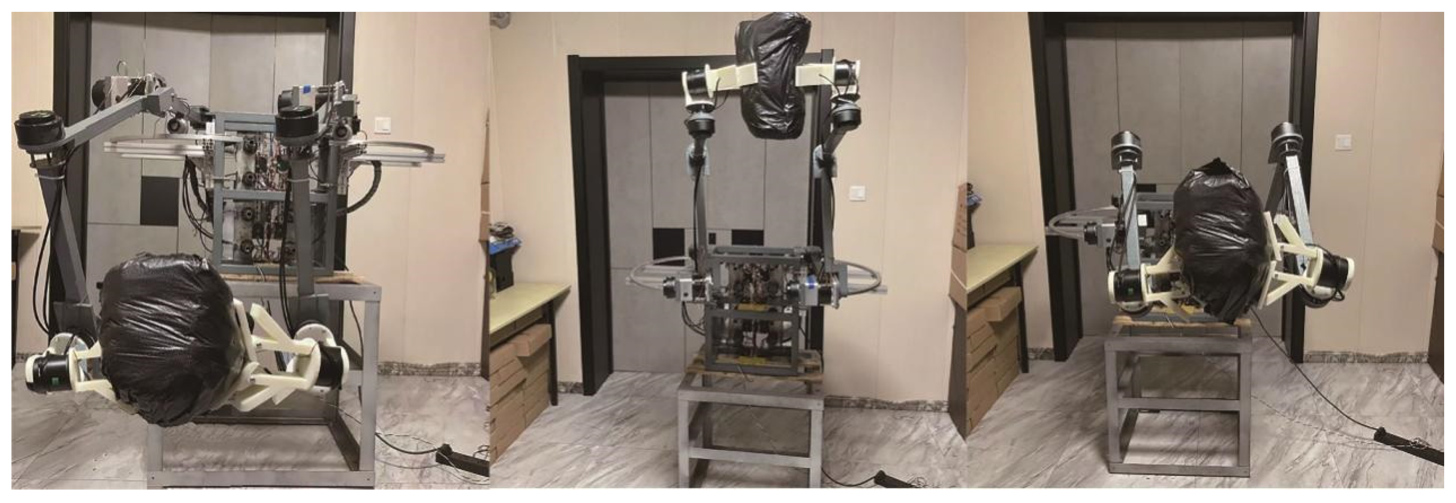
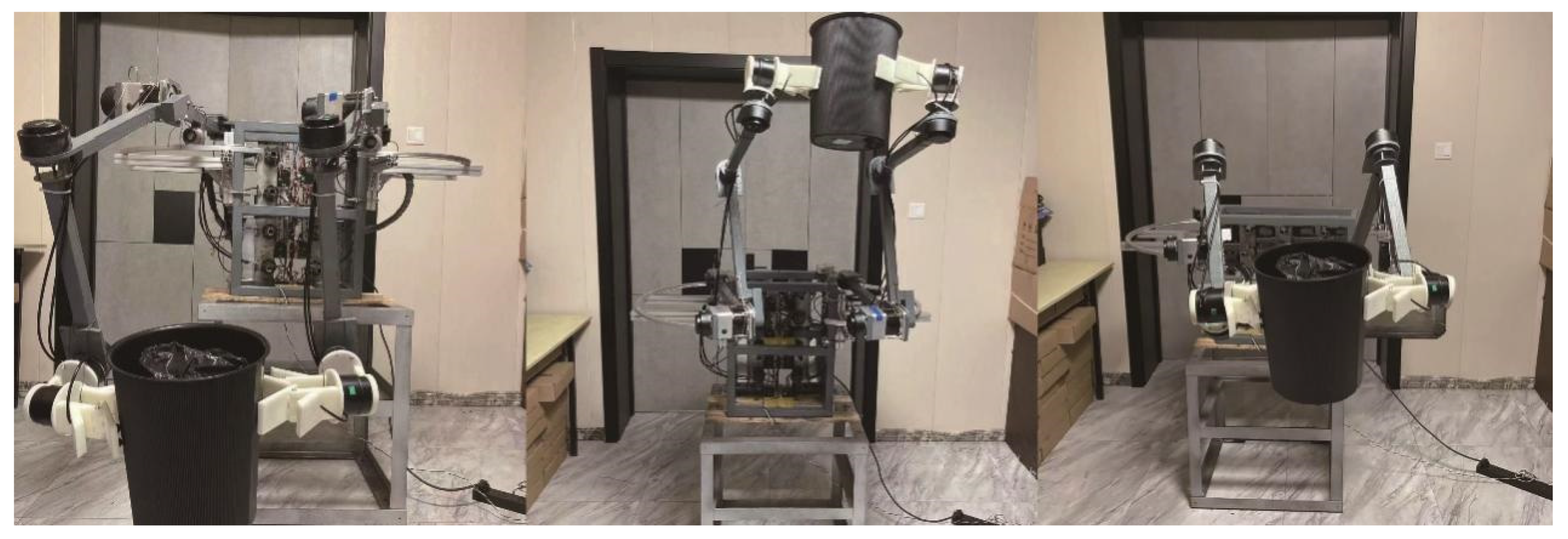
This paper considers the process of a humanoid remote operation robot equipped with 4 end effectors to manipulate objects with unknown information other than visual.
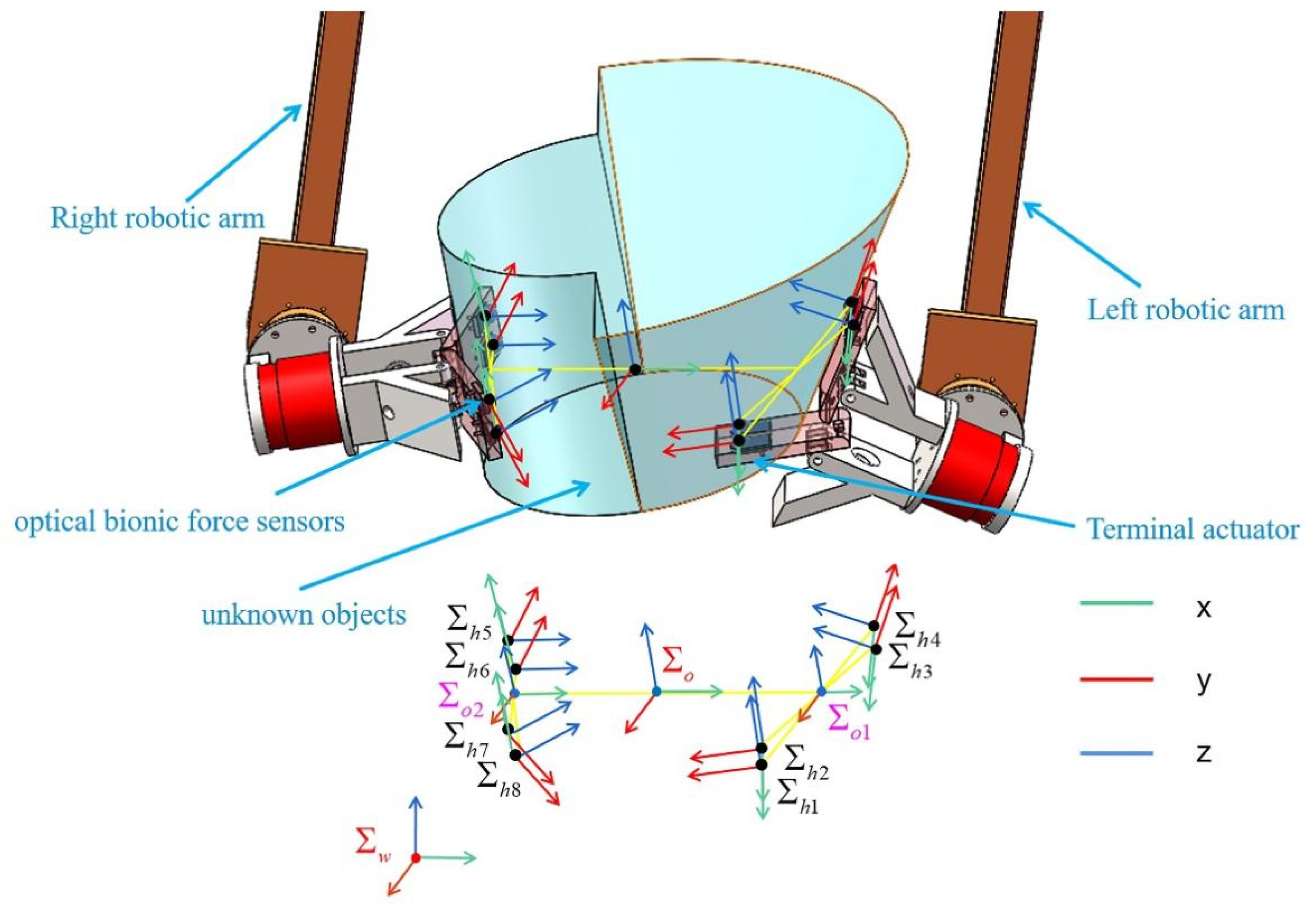
Figure 1 illustrates each terminal having two customized optical bionic force sensors. These 4 terminals cooperate to stably clamp unknown objects and maintain adaptive stable handling without relative sliding during any collaboration of the remote operation or on the planning path. This paper makes the following assumptions:
Remote operation enables each force-sensing contact point installed at the terminal to reach a reasonable, cooperative position on the object's surface, and all contact points contact the object's surface.
The remote operation causes the four terminals to form an origin
in the coordinate system
, as illustrated in
Figure 1, which is close to the object's center of gravity.
A virtual rod defines the force space control vector in a multi-terminal multi-contact point collaborative system [
16]. The contact point of this paper is a three-dimensional optical bionic force sensor (
Figure 1). The coordinate system
represents the contact point coordinate system (
). Nevertheless, the proposed method applies to more contact points and terminals.
Coordinate system, respectively. and represent the planar center coordinate system formed by the four coordinate system origins at the contact points of the two terminals installed on a single robotic arm.
In this paper,
is set at the midpoint of the connected line of
and
. The virtual rod
from
to
is equivalent to a rigid rod structure fixed at the contact point. The virtual rod top coordinate system
initially coincides with the object coordinate system

.
The force vector generated at the top of
is defined as
Where
and
are the force and moment applied at the tip of the virtual rod
. The prefix
indicates that the vector is defined in the robot's coordinate system
. The vector
is calculated from the force and moment applied to the object by the contact terminal
. The sum of the combined forces on an object
and moment
is calculated from the sum of

.
Where
,
, and
is a
identity matrix with a rank of 6 because the matrix
maps
dimensional vectors to 6-dimensional vectors. Therefore, its null space range is
-dimensional,
in this paper. We define
as the null space basis of
. The general interpretation of Equation (2) is
Where
is an arbitrary
-dimensional vector corresponding to
and
is a generalized inverse matrix of
.
Note that belongs to the null space of . So corresponds to the internal force/moment that can be controlled separately without affecting the net force. Besides, and are not fixed, which is important for the follow-up force tracking control.
Equation (3) can be rewritten as
Where
is a generalized force vector. The internal forces
can be expressed as
dimensional force vector set
For the given
, the force/moment vector
is obtained by solving Equation (4).
Next, we introduce stable clamping and handling with multi-contact points in inner and outer working spaces, utilizing simultaneously and independently controlling vectors and the required coordinate systems. The physical meaning of this setup is summarized as follows. Matrix maps the forces exerted by multi-terminals and multi-contact points to the external forces of the object. Matrix is the null space basis of , and matrix maps a set of external and internal forces to the forces of multi-terminal contact points.
2.2. Simplification and Transformation of Internal Force Space
Next, we discuss the stable clamping internal force of the multi-point contact collaborative handling system proposed in this paper. When more than two contact points conduct a collaborative clamp, it is difficult to determine the null space basis
proposed in
Section 2.1 because
does not represent the intuitive meaning of the internal force/moment. Hence, we write Equation (6) as follows
Thus, Equation (6) becomes
Once the 7 internal force vectors
are given, matrix
is determined automatically. However, under the same net force requirement, the internal force vector
has an infinite number of values. This paper determines the internal force direction of stable clamping according to the terminal model. Thus, the desired internal force for stable clamping is adaptively tracked under this set of internal force directions. Therefore, we extract the internal force vector Equation (9) from Equation (8)
We simplify the internal force workspace according to the terminal model characteristics to reduce computation and for system simplicity. Specifically, considering that the model involves internal and external forces for stable clamping without losing generality, we make the following reasonable assumptions:
No torque vector is formed at a single contact point.
No internal force is generated between two parallel contact points on a terminal.
No internal torque is generated between all contact points, so only internal forces are involved in control based on reference trajectories.
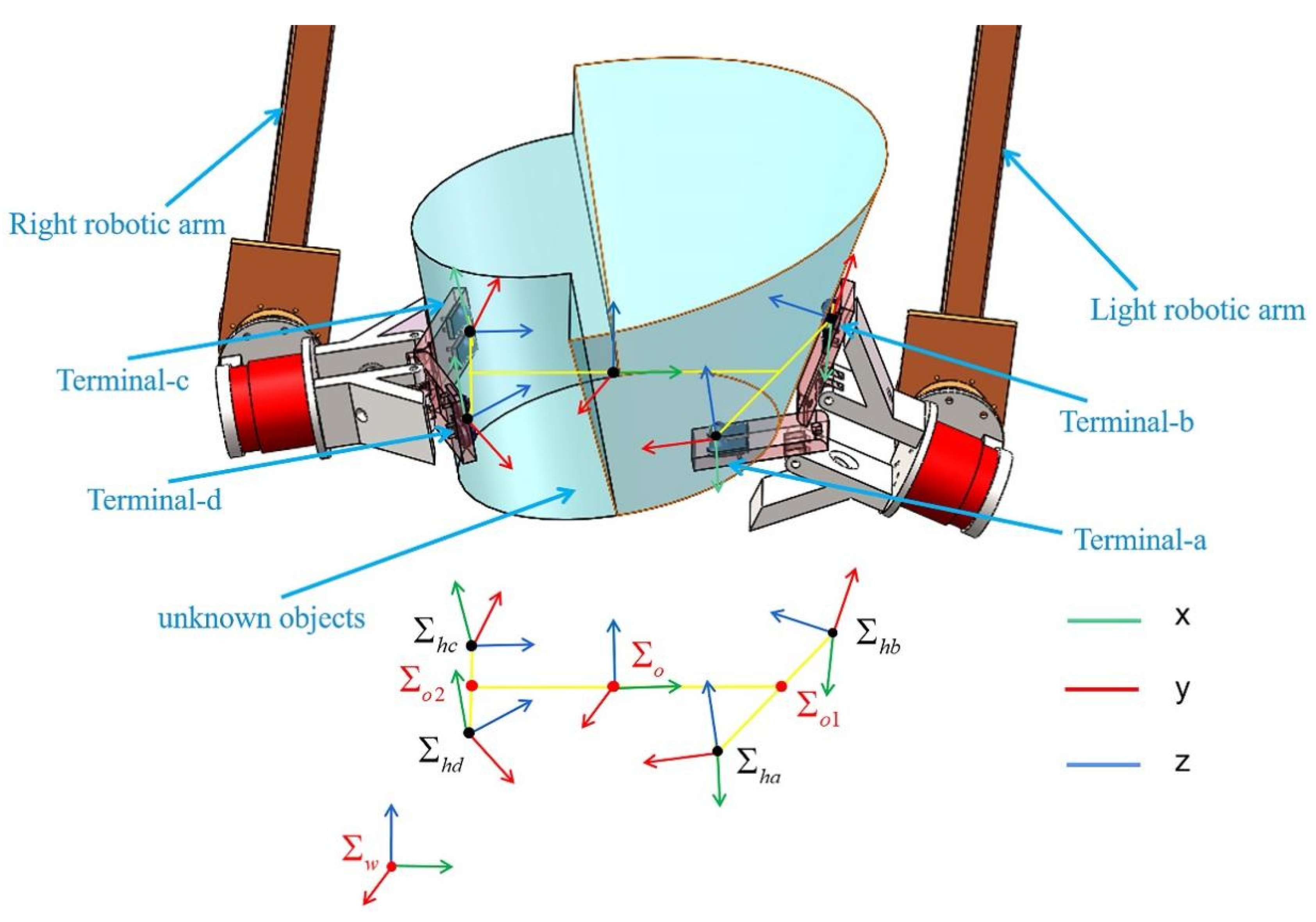
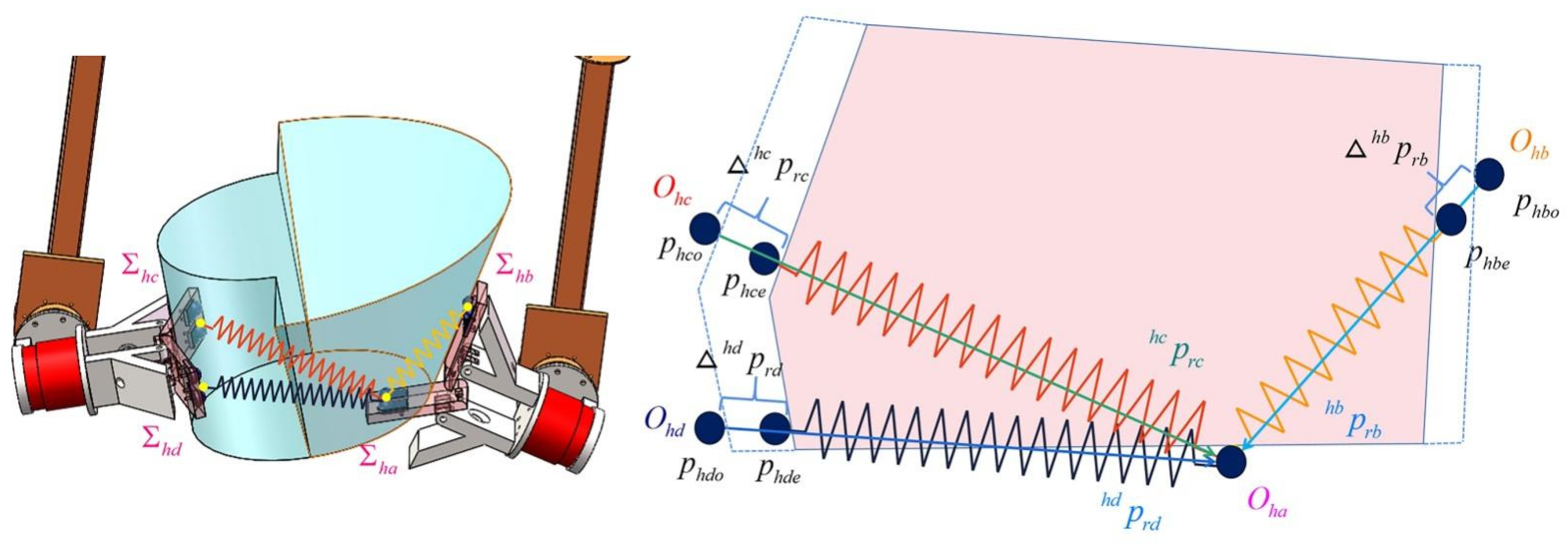
Based on the above assumptions, the initial internal force workspace becomes a four-contact terminal force vector workspace. According to the system model depicted in
Figure 2, the coordinate system at the contact points
and
are merged into
. The new coordinate direction remains unchanged, while the origin changes to
at the midpoint of the connected line
and
. Furthermore,
as a new cooperation terminal, its force vector is determined by the force vector combination at the contact point
and
. We merge
and
to form
, and merge
and
to form
, and merge
and
to form
in the same way. As presented in
Figure 2, the force vector is simplified similarly. Therefore, the force vector applied to the object by the 8 terminal contact points
described in
Section 2.1 becomes
, and accordingly, the force/moment vector at the tip of the virtual rod
becomes
. So Equation (7) becomes
Defining the direction of the intuitive force while handling the object with the human hand is trivial. Therefore, the following internal force group is used as an intuitive force given to the expected internal force group
So, matrix
from Equation (11) is determined as the intuitive expectation value matrix
as follows
The simplified generalized internal force vector
is the expected generalized internal force vector. Thus, Equation (11) becomes
Although the expected internal force vector determined in Equation (13) is intuitive and in line with conventional thinking from the perspective of understanding, it significantly increases the difficulty of setting the parameters. It even makes it impossible to achieve favorable control from the perspective of control. Therefore, we perform a favorable transformation of the internal force workspace appropriate for the control method proposed in this paper. Considering the robustness of the multi-terminal adaptive scheme introduced in this paper, it is necessary to determine one of the terminals and control its absolute motion to afford to realize the other terminals to control the force tracking the relative motion of this terminal.
Note that the internal force vector does not contribute to the object's motion but represents the mechanical stress exerted on the object. There are infinite representations of internal force vectors as null space vectors. One of this paper’s contributions is that the time-varying complex internal force space is difficult to determine and accurately control the collaborative task of manipulating unknown objects using multi-terminals, which is modeled as an accurate controllable space.
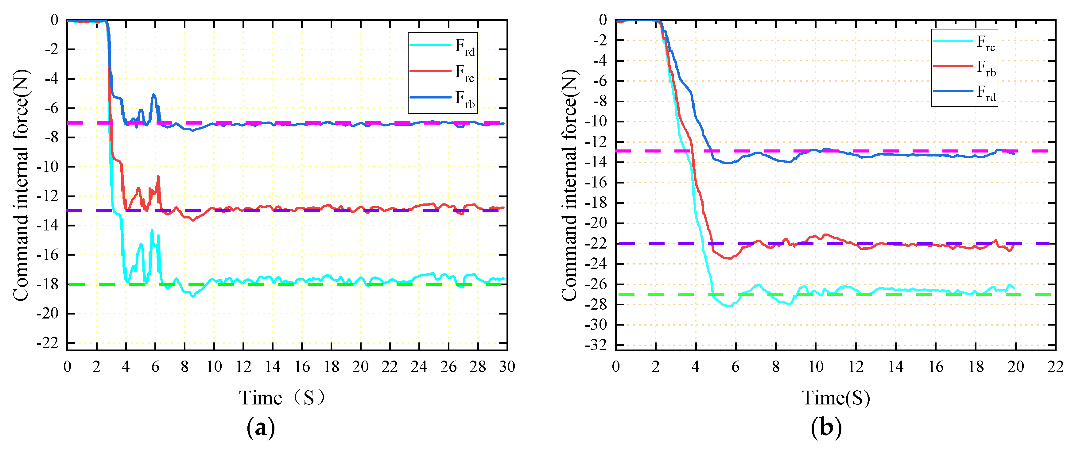
Based on the model Equation (10), the selected internal force group is used as the control variables and converted to meet the control needs. In this paper, the desired internal force group in Equation (13) and the internal force group from the slave terminal position to the master terminal are converted as follows to achieve the control goal. The internal force group from the slave terminal to the master terminal is defined as follows
Matrix
determined by Equation (14) will be named
as the internal command force parameter
When
is determined as a generalized command internal force vector, then Equation (14) becomes
If we determine the expected internal force set, the command internal force group is uniquely determined since we can make the following conversion between Equations (13) and (16).
Where is the generalized inverse of . The transformation in Equation (17) is critical for introducing force-tracking adaptive control.
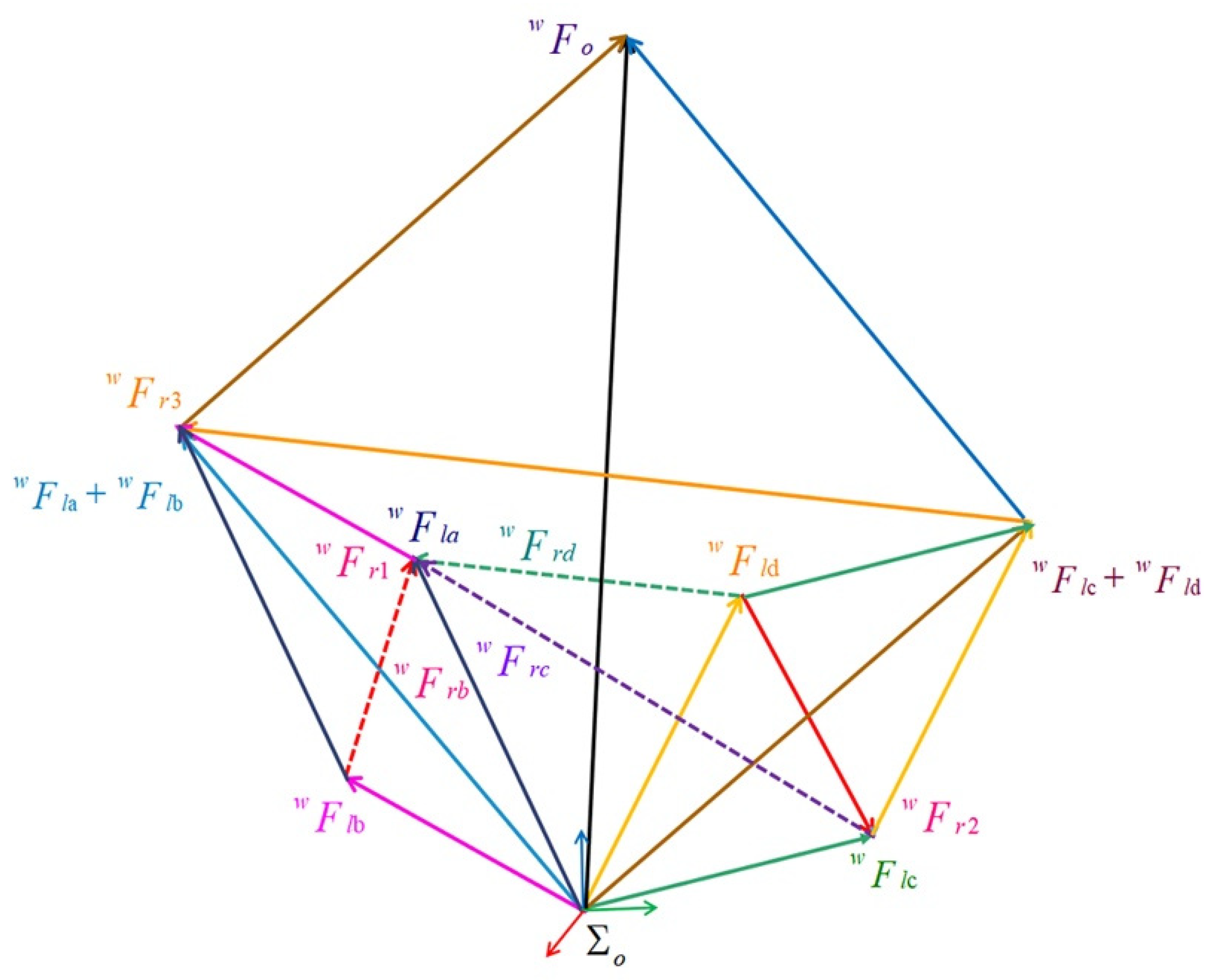
The relationship between the expected and the command internal force in Equation (17) is represented in
Figure 3, where the force applied by each terminal on the object is transferred to the origin of the object coordinate system through a virtual rod.
represents the intuitive expected internal force extracted from Equation (11) in
, and
is the internal instruction force as the key control quantity in this article. Due to the four terminals in zero space, the combined external force
applied to the object is controlled near a fixed value according to the internal force in changing the demand of the object's movement. It is easy for operators to regularly observe the internal force
Through observation, we conclude that it meets the demand for stable clamping of objects. However, as a control variable, achieving internal force tracking tasks is difficult because a tracked end is a tracking end itself, which poses significant difficulties to the controller design. Due to the four terminals in zero space, the combined external force F applied to the object is controlled near a fixed value according to the internal force in changing the demand of the object's movement. In order to solve such difficulties, this article proposes the instruction of the internal force
(extracted from
in Equation (14)) through (11) - (17). As shown in
Figure 3,
is the internal force between one terminal and the other terminals, which is crucial for force tracking control. If this end is determined as the absolute motion control object, it will solve the problem that the tracked end itself is the tracking end. This greatly reduces the uncertainty of control. As shown in Equation (17),
is uniquely determined when
is determined. In
Section 3, we will track a fixed
on a one-dimensional holding line while determining
.
2.3. Absolute Relative Motion Control
Human hands can hold and handle unknown large objects of any shape in any way stably and flexibly. It is worth highlighting how complex time-varying internal forces and motion are regulated through perceptual intelligence. This paper simulates the ability of humans to develop a multi-terminal robot control algorithm. In the above human process, the person can perceive that any part of his palm is in contact with the object and can be consciously determined as the master terminal, while other parts of the palm in contact with the object can be determined as the slave terminal. Moreover, the slave terminal clamp (increase the internal force) to the master terminal is determined by consciousness to stabilize the clamping. Furthermore, it is important to keep the relative movement between the master and the slave terminal within a small stable range (time-varying force and motion tracking). Similarly, the task space of the robot can be broadly divided into the combined motion of the absolute motion of the master terminal and the relative motion from the slave terminal.
The absolute motion is performed by the master terminal and is designed to achieve accurate and robust tracking of the target reference trajectory. On the other hand, relative motion is conducted by the slave terminal, designed to accept the movement of the master terminal. Thus, the so-called closed kinematic chain constraints can be satisfied. In this paper, the
presented in
Figure 2 is identified as the master terminal, Terminal-a, responsible for absolute motion control. The rest
are slave terminals, named Terminal-j
, responsible for relative motion control.
Figure 2 illustrates the relationship between each terminal and object motion in the robot coordinate system. which can be explained with the following equation
Where is the position vector of the simplified four terminals in the robot coordinate system, is the cross product executed by the oblique symmetry matrix operator, represents the transformation matrix of each terminal coordinate system relative to the robot coordinate system, and are the translation velocity and angular velocity of the object in the robot coordinate system, respectively, and is the virtual rod represented by the terminal coordinate system.
The relative position
and orientation
of the three slave terminals Terminal-j
and the one master Terminal-a in Equation (18) are expressed in the slave terminal coordinate system as follows
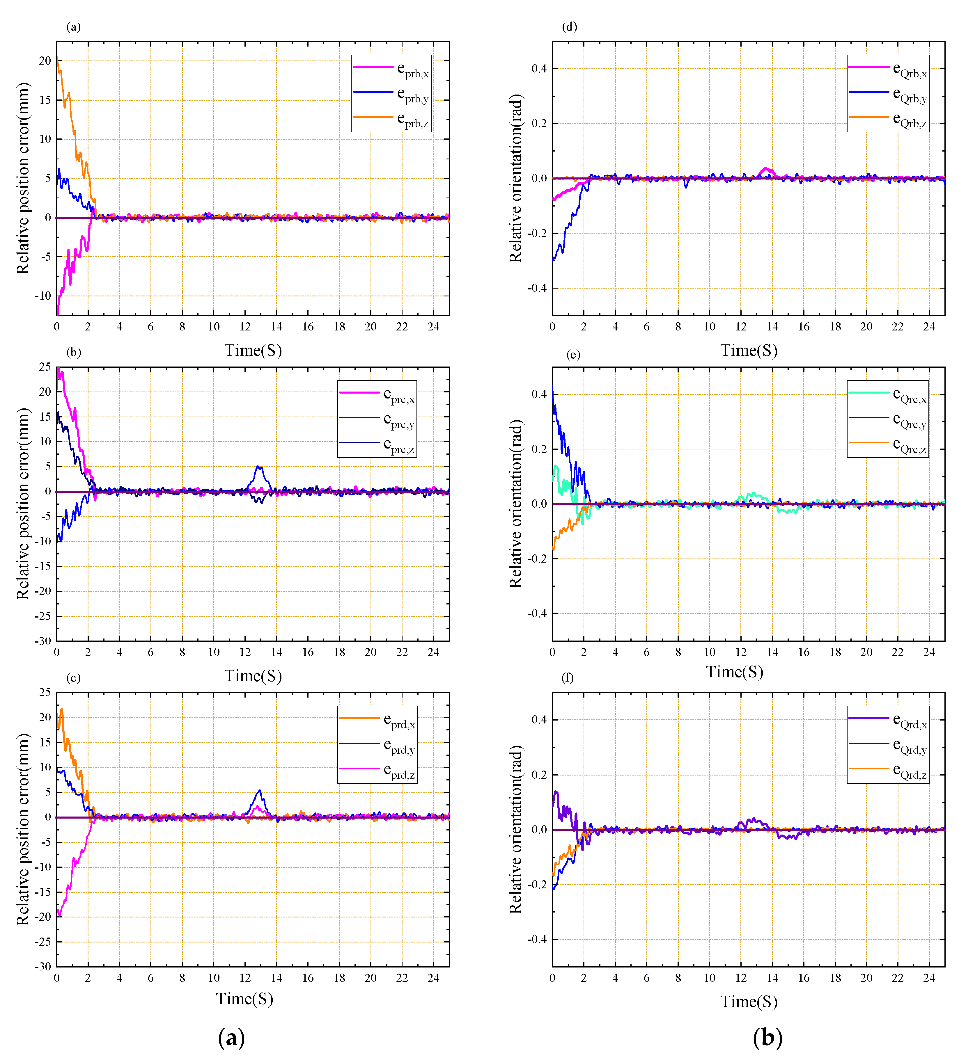
In an ideal state, there is no relative motion between each terminal, so the relative position and orientation should remain constant.
The robot coordinate system is the default and will be omitted in subsequent equations. For time t, the expected translation velocity and angular velocity corresponding to the object are expressed by
and
. According to Equation (18), we will get the expected translation velocity
and angular velocity
of the master terminal as follows
Where represents the absolute position error of the master terminal, indicates the absolute direction error of the master terminal, and is the sampling time step; is the command position of the last sampling time. is the measurement position of the current time, is the desired direction at the last sampling time, with representing the direction measured at the current moment. Note that only and are consistent, while will be zero.
Once the Cartesian velocity of the master terminal is established, the desired velocity of the slave actuator can be determined by
Where , is the master terminal translation velocity, is the relative position initialized from the terminal coordinate system extracted from the terminal gesture by (19).
Where indicates the relative position error of each slave actuator under the robot coordinate system and indicates the relative direction error of each slave terminal under the robot coordinate system. Similarly, and represent the expected relative position and direction expressed in the slave actuator coordinate system, respectively.
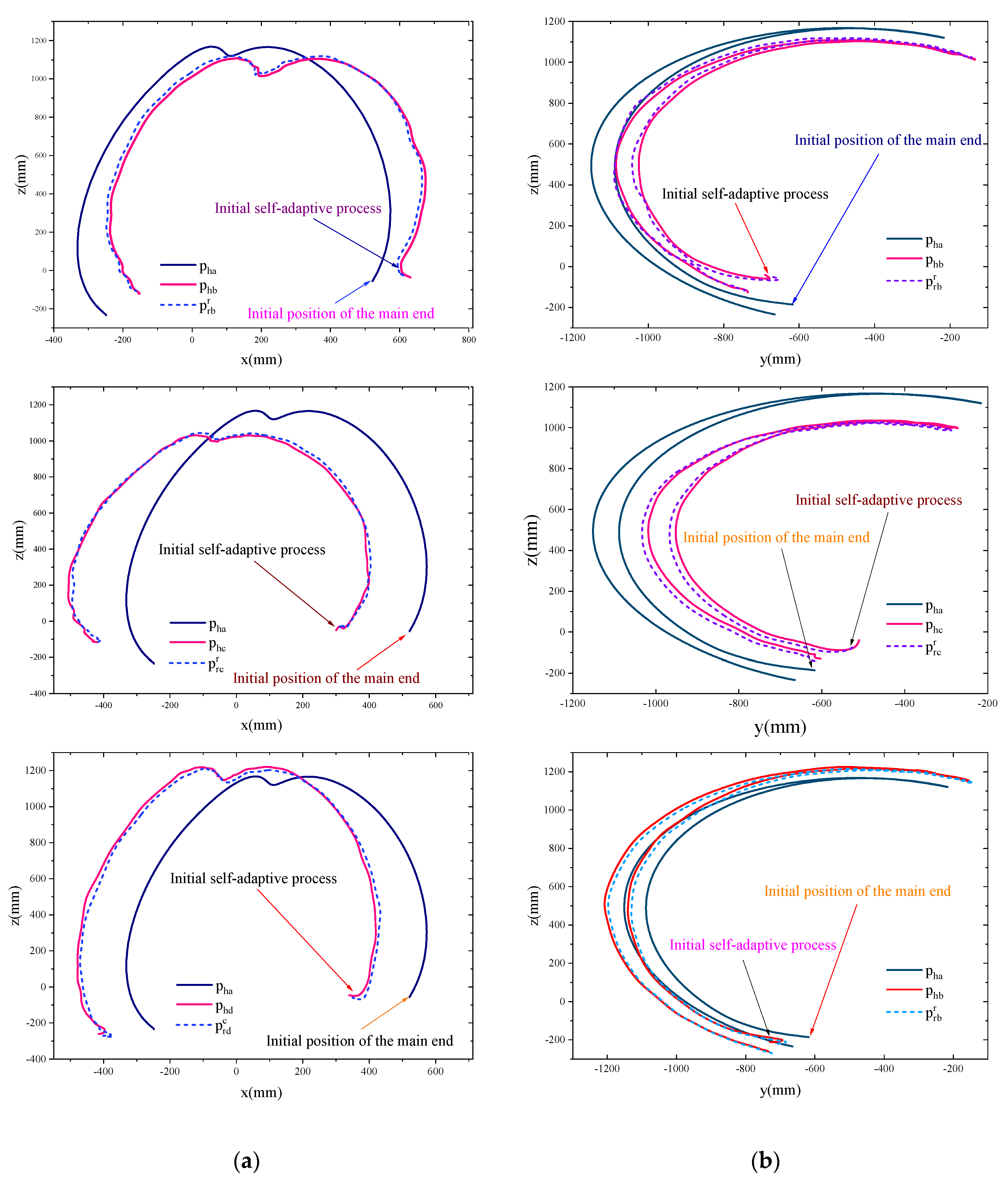
With the above closed-chain constraint method, we can quantitatively calculate the absolute and relative motion of the four terminals accordingly for the desired position and orientation of the object. The advantage of using a master-slave closed chain constraint control is that multi-terminal systems can perform collaborative tasks without knowing the information about the shape, size, and stiffness of the object.
 .
. .
.
 converges to 0.