1. Introduction
The efficacy of intracavitary high dose rate (HDR) brachytherapy in post-operative endometrial cancer has been established for decades.1-5 Clinical data indicates that HDR vaginal cuff brachytherapy (VCBT) not only provides a large curable dose to an endometrial lesion, but also reduces the risk of recurrence in the vagina and causes significantly less toxicity than pelvic external-beam radiation therapy 6,7. Although a single channel cylinder (S-cylinder) HDR VCBT is still the standard for early-stage endometrial cancers in most radiation oncology clinics, the multiple-channel cylinder (M-cylinder) HDR VCBT is gaining popularity, due to its improved versability in certain clinical scenarios.8-10 By utilizing multiple source positions in closer proximity to the target, M-cylinder HDR VCBT allows dose to be preferentially delivered to specific portions of the vagina.11,12 This can translate into advantages compared to S-cylinder HDR VCBT as the non-cylindrical target can be more adequately covered while simultaneously decreasing dose to OAR.8,13 After all, the M-cylinder HDR VCBT is still simple, convenient and effective, additional features, such as the MRI compatibility and peripheral multichannel structure, make M-HDR applicators beneficial for non-cylindrical dose distribution delivery for asymmetrical tumor targets.10,14-16
Although some dosimetric studies comparing S- and M-cylinders have been performed,16 a direct comparison between the 3D doses respectively delivered by a S- and M-cylinder to the same cylindrical target volume particularly for VCBT, has not been fully conducted. Modern trends in radiation delivery (e.g., IMRT and radiosurgery) use more beam angles in an effort to achieve homogeneous and highly conformal dose distributions with steep gradients outside the target volume. Doses received in the target volume are likely be different when using different types of cylinder applicators, it is important to know how added brachytherapy dwelling channels and points will affect dosimetry in a cylindrical target volume. For an M-cylinder applicator, those additional channels are located at the peripheral region of cylinder body and closer to the surface than the central channel. Because the multiple channels were placed at the locations closer to the target than the central channel of S-cylinder, the M-cylinder may be able to provide a different dose distribution to the cylindrical shell-like target volume, if the multiple peripheral channels were employed instead of single central channel for the HDRVCBT. The purpose of this study is to evaluate the dosimetric impact of multiple peripheral channels compared with a single channel in HDR VCBT using a cylindrical shell target volume.
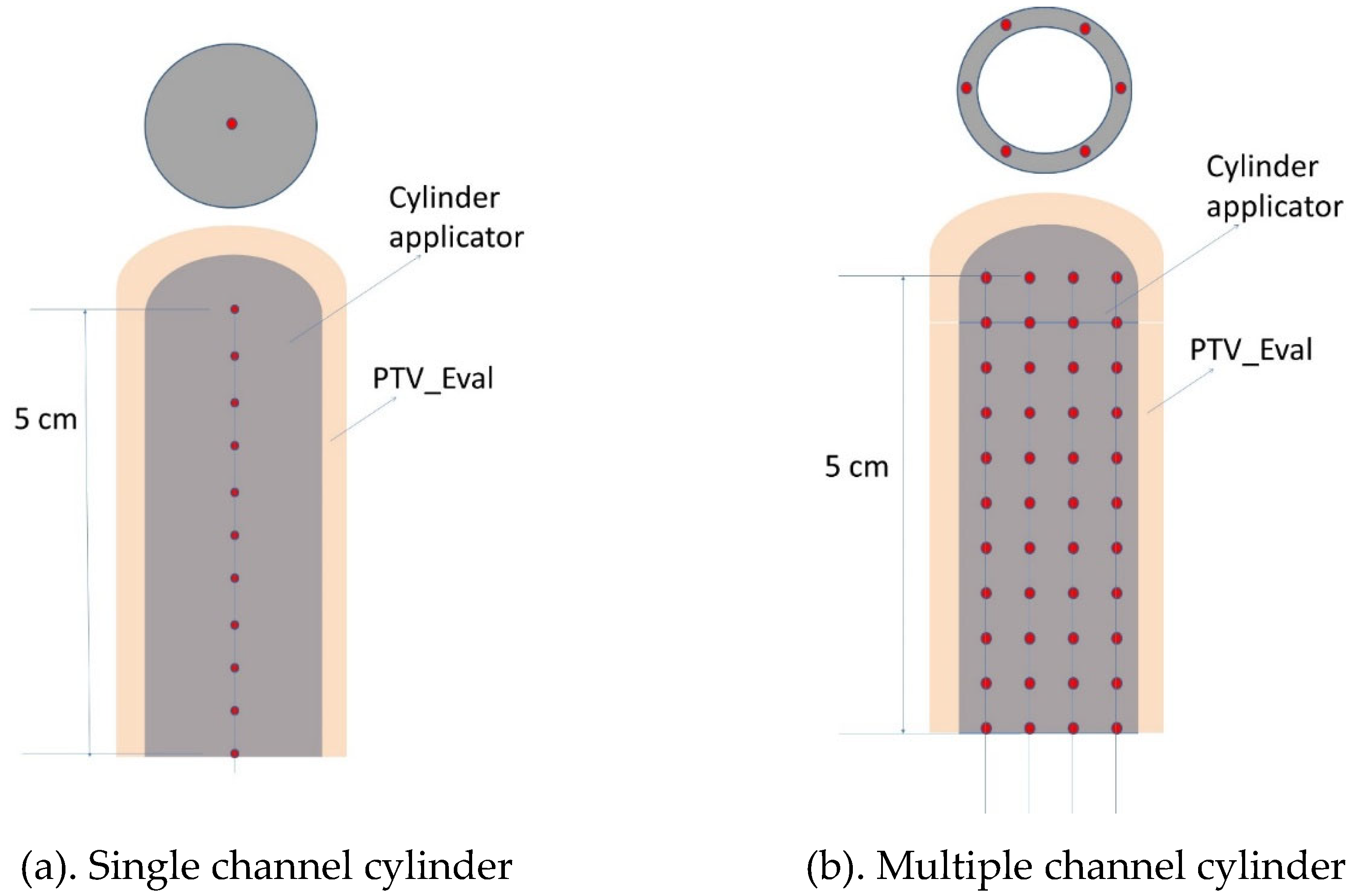
Figure 1.
Schematic cross-sectional views of single channel (a) and multiple channel (b) cylinder applicators for HDR VCBT procedure.
Figure 1.
Schematic cross-sectional views of single channel (a) and multiple channel (b) cylinder applicators for HDR VCBT procedure.
2. Materials and Methods
In this study, a series of HDR VCBT plans were generated by a treatment planning system (TPS) (Oncentra version 3.5, Elekta AB, Stockholm, Sweden) from a list of sample CT images with various sizes of single and multiple channel cylinder applicators. Per our clinical guidelines, two different fractionation regimens were planned for HDR VCBT: 1) 5.5 Gy prescribed to 0.5 cm depth delivered for 4 fractions, referred to as the 5-mm regimen; and 2) 8.8 Gy prescribed to the surface of the cylinder delivered for 4 fractions, referred to as the surface regimen hereafter. The treatment regimens were selected from the ABS (American Brachytherapy Society) recommendations, 17 their equivalency was evaluated in a recent study.18 The evaluation target volume was a 0.5 cm ring surrounding the cylinder with different treatment lengths, named PTV_Eval. The rationale for using this target volume was based upon data,19 that approximately 95% of vaginal lymphatic channels (a potential surrogate for cancer cell location) are located within a 0.3 cm depth from the vaginal surface and that the density of lymphatic channels decreases with the depth. Thus, a depth of 5 mm is thought to be adequate to cover the majority of potential microscopic disease.
2.1. S-HDR VCBT Plans
An HDR unit with an 192Ir source was used for HDR VCBT. A brachytherapy treatment planning system (TPS) (Oncentra, version 3.5, Elekta) was used to create HDR VCBT plans utilizing single channel cylinders (S-cylinder) (Nucletron, Elekta AB, Stockholm, Sweden) with a range of diameters (2.5, 3.0, 3.5 cm).
Sample CT images with various S-cylinder applicator sizes were scanned in 2-mm slices and used to make CT image-guided HDR VCBT plans. To determine the dwell positions of the source, the central thin tube of the cylinder applicator was first tracked in the TPS “Catheter Construction” workspace starting from the tip/edge of white bar and extended until 10 cm long, in the coronal or sagittal view with the “start from tip-end” tracking option. For the cylinder applicators involved in this study, the tip of the central tube is the tip of the applicator head. A tip space, the distance from the tip of the applicator to the first source dwell position (-6 mm) was experimentally determined and entered in the catheter construction. All other dwell positions were laid out after the first position with the 0.5 cm step size. A 5-cm treatment length, for example, had 11 dwell points (
Figure 1).
In this study, the HDR VCBT plans were generated as follows. A set of reference points were created at the prescription depth at each source dwell position. These “axis points” were used to normalize the prescription dose, then a “distance optimization” method offered by the TPS was further applied. The method of the axis points plus distance optimization was used simply because this method is simple and can be easily adopted by other brachytherapy TPS. The most proximal dwell point was not used to create a corresponding reference point, to avoid excessive extension of the prescription isodose line. The planning method of this study was the same as that used in other studies. 6,18 By analyzing the dose volume histograms (DVH) of target, the mean doses (D-mean) and the doses covering 90% (D90), 10% (D10), and 5% (D5) of PTV_Eval of S-Cylinder HDR VCBT and M-Cylinder HDR VCBT plans were calculated and compared.
2.2. M-cylinder HDR VCBT plans
In the same manner as the S-cylinder, sample plans of HDR VCBT in a list of M-cylinders at 2.5, 3.0 and 3.5 cm in diameter were created and analyzed. For a fair comparison, the doses were still prescribed either at the 0.5 cm depth with 5.5 Gy for 4 fractions or at the cylinder surface with 8.8 Gy for 4 frac tions, at the treatment lengths of 3, 4, 5, 6 and 8 cm. A 0.5 cm depth ring volume (PTV_Eval) (
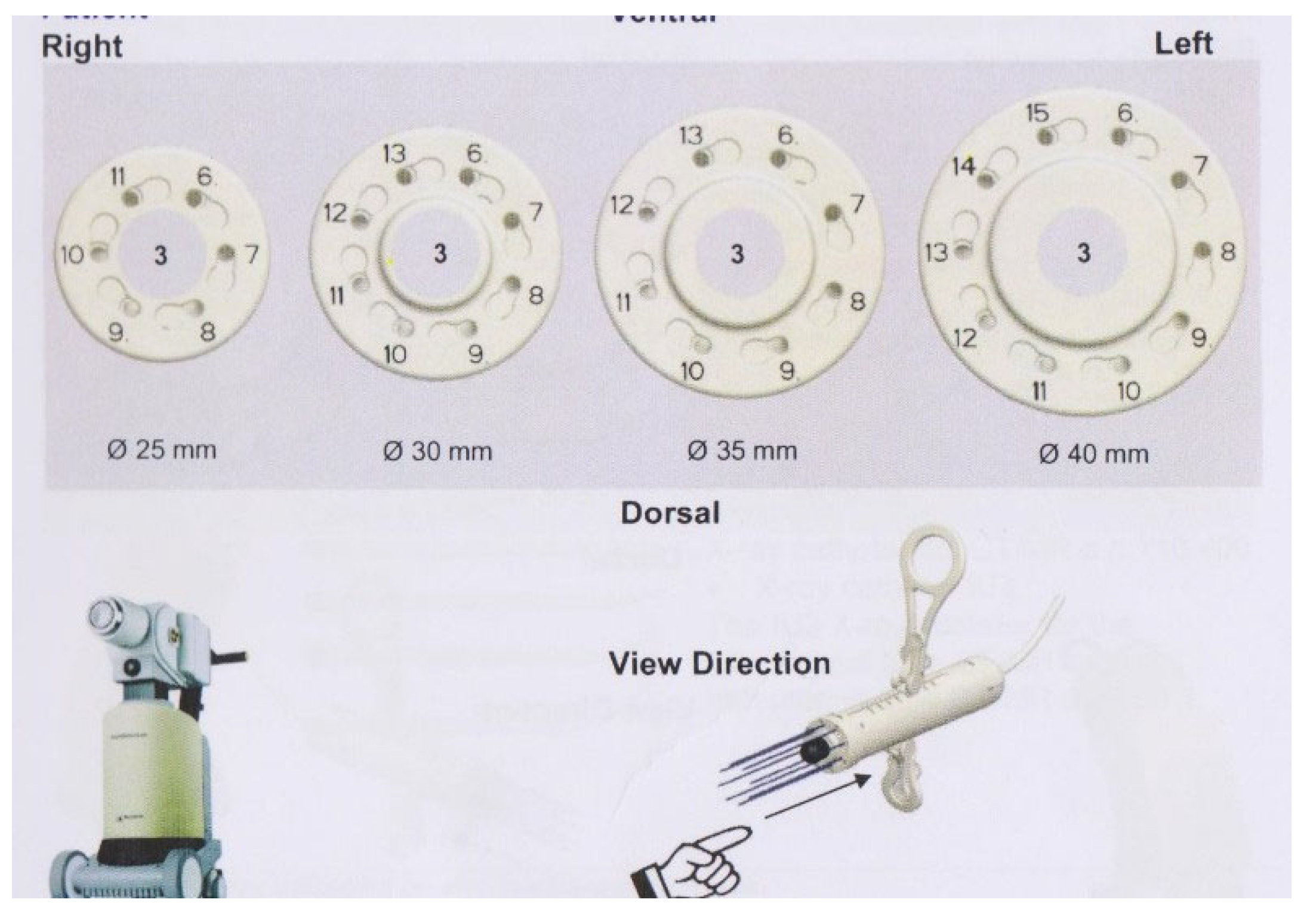
Figure 1) for each treatment length was contoured and served as the target volume for dosimetric evaluation. To determine the dwell positions of the source in all channels, all the peripheral channels of M-cylinder were tracked in the TPS “Catheter Construction” workspace starting from the tip/edge of black tip and extended until 10 cm long, in the coronal or sagittal view with the “start from tip-end” tracking option. The central channel was tracked and used as a surrogate for creating four sets (-X, +X; -Y, +Y) of reference points for each prescription regimen since the distance from the central channel to the prescription depth is known, although the central channel was set as zero dowelling time. The central channel was not used for delivering any radiation, as we wanted to examine the impact of all peripheral channels. Our tests indicated that the involvement of central channel would compromise the impact of peripheral channels in the symmetrical cylindrical tumor target volume, although in a real M-cylinder case in which an asymmetrical tumor target was treated and the central channel was usually employed. The central channel has a -6 mm tip space, all peripheral channels have a -3 mm tip space. These reference points were used to normalize the prescription dose. All peripheral dwell points within the treatment length except for the last (most proximal) points of all channels were set active and assigned with the same weighting factor. Same as the S-cylinder, the last dwell points were not used in the planning for avoiding excessive extension of prescription isodose line. The isodose lines were further shaped with the distance optimization method.
Figure 2, M-Cylinders for 2.5, 3 and 3.5 cm with position of peripheral channels.
3. Results
3.1. Mean doses of HDR VCBT with S-cylinders and M-cylinders
Table 1 and
Table 2 list the mean doses of different diameters and treatment lengths for the M- and S-cylinder HDR VCBTs, respectively for both regimens. Results demonstrate both types of cylinders produced very similar mean doses for both regimens.
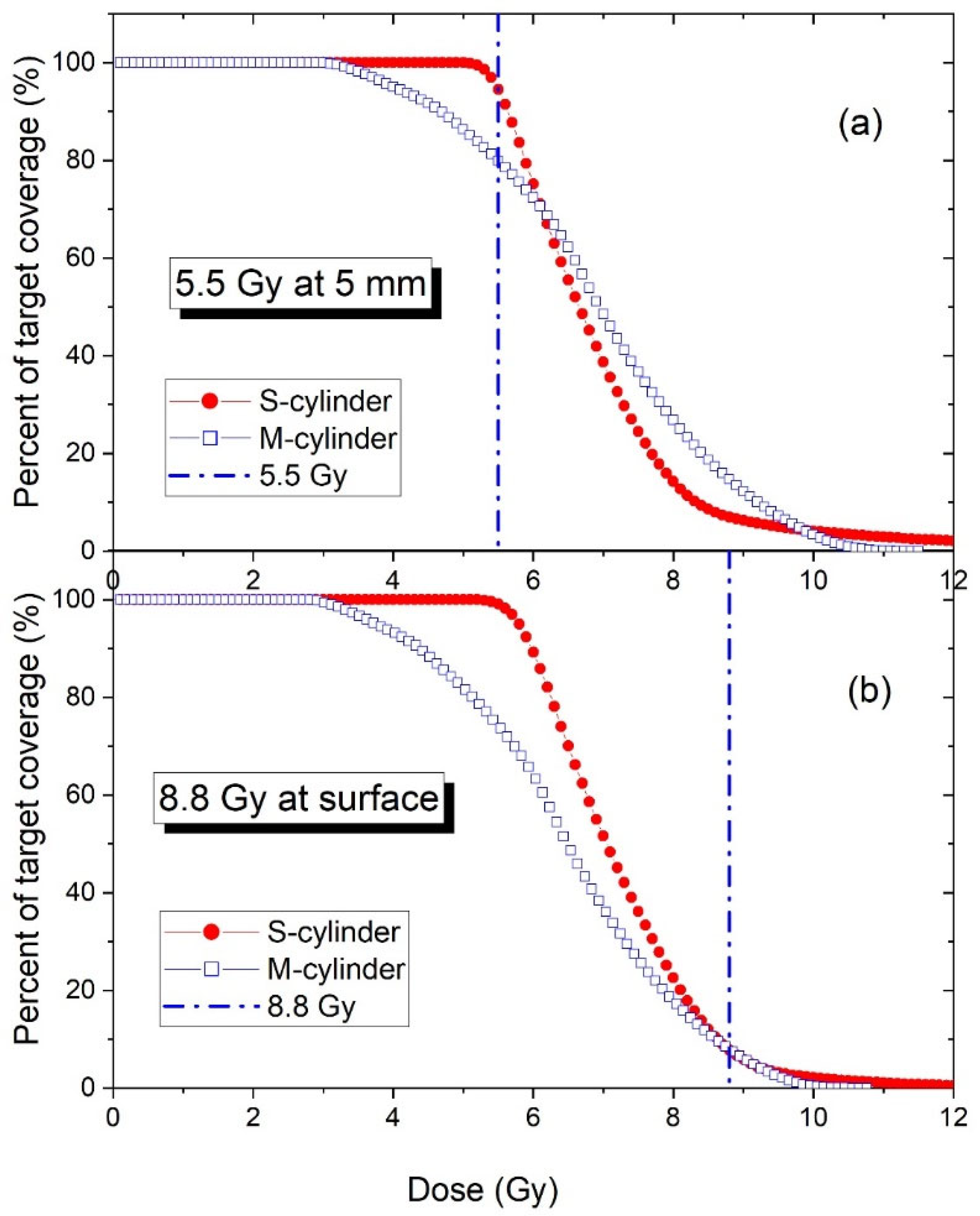
The DVHs of all plans were calculated. An example of DVH curve comparison between a similar size of M- and S-cylinder HDRVCBT is shown in
Figure 3. It shows that an S-cylinder’s DVH curve drops faster than an M-cylinder, so a S-cylinder HDR VCBT produces more uniform dose than a M-cylinder HDRVCBT. This is because a M-cylinder’s source dwell positions are closer to the target surface than a S-cylinder’s, therefore the Ir-192 source’s steep radial dose function at the short distance
20 makes the dose distribution of PTV_Eval more heterogeneous.
3.2. Doses covering 90%, 10 and 5% of target volume
Table 3 lists the doses covering 90% of target volume (D90s) of both types of cylinders with different diameters and treatment lengths. For both the S- and M-cylinders, the dose covering 90% of volume is independent of treatment length; but a smaller diameter will deliver a smaller dose for covering 90% of target volume in the surface prescription regimen; by decreasing the diameter from 3.5 to 2.5 cm, the dose will drop by 9% and 30% respectively for a S- and M-cylinder. However, in the 0.5 cm depth regimen, S-cylinder will give the same D90 regardless of its diameter and length, but a M-cylinder will produce a smaller D90 for a smaller diameter, a 23% dose drop when the diameter is decreased from 3.5 to 2.5 cm.
Table 4 and
Table 5 listed the doses covering 10% and 5% of target volume (D10s and D5s) respectively. These dose metrics are from the DVH curve high dose tails, they represent the high doses received by a significant percentage (10% and 5%) of target volume. D10 and D5 were found slightly decrease (<10%) with the increase of diameter (from 2.5 to 3 cm) and treatment length (from 3 to 8 cm) for both types of cylinders. For the same diameter of cylinder and treatment length, the D10 and D5 of M-cylinder are smaller than that of S-cylinder in the 5 mm regimen, but greater in the surface regimen.
4. Discussion
The mean doses of S-cylinder and M-cylinder HDR VCBT indicated that, the prescription of 5.5 Gy at the depth of 5 mm is equivalent to the prescription of 8.8 Gy at the cylinder surface. (
Table 1 and 2). The dosimetric isoeffects of two prescription regimens in M-cylinder HDR VCBT were further indicated in
Table 3, 4 and 5 on the dose metrics through D90, D10 and D5. In the S-cylinder HDR VCBT, the metrics of D90, D10 and D5 generated from 5.5 Gy prescribed at the 5 mm depth are same as the prescription of 8.8 Gy prescribed at the cylinder surface, as indicated in the literature.
17,18 Our study indicated that this is also true for the M-cylinder HDR VCBT, as shown in
Table 3,4 and 5. That implies that the M-cylinder HDR VCBT can utilize the clinical experience gained from the S-cylinder HDR VCBT when the cylindrical target volume is treated.
At present a classical radiation therapy usually strives for a uniform dose delivery. For a non-uniform dose treatment, a ratio of D10/D90 or D5/D95 is used to indicate heterogeneity.21,22 D10/D90 is 1.96 for a 3-cm M-cylinder and 1.50 for a similar diameter S-cylinder. This indicates that, for treating a cylindrical shell target volume, the added extra peripheral channels do not contribute to the increased dose uniformity. On the contrary, the dose of PTV_Eval tends to become more heterogeneous, when the treatment is switched from a S-cylinder to a M-cylinder. This is because the source locations of the peripheral channels of a M-cylinder are closer to the target surface than that of the S-cylinder, the Ir-192 source has a steeper radial dose function at the short distance than at a lager distance (>1 cm), this resulted in the delivered dose with many peaks and valleys through a M-cylinder, thus demonstrated a more heterogeneous dose distribution.
Although the multiple channels did not generate an increased dose uniformity, but the impact of cylinder size of M-cylinder is slightly less than the S-cylinder. A 0.5 cm variation of diameter will result in just a 2% change of D-mean in the M-cylinders, comparing 4 % in the S-cylinders.
5. Conclusions
Our study indicated that, (a) Both S- and M-cylinders had similar mean doses with both the surface and 5 mm depth prescription regimens across all treatment length combinations; (b) S-cylinder HDR VCBT plans are simpler and less heterogeneous; (c) M-cylinder HDR VCBT although is more heterogenous and can still adequately cover the symmetric target volume but is best suited for asymmetric volumes.
Financial disclosure/Conflict of Interest
The work was not supported, funded, or sponsored by any extra-institutional source, nor are there any actual or potential conflicts of interest with the production or publication of this work. No author has any direct or indirect commercial financial incentive associated with publishing this article.
References
- Diavolitsis V, Rademaker A, Lurain J, et al: Clinical outcomes in international federation of gynecology and obstetrics stage IA endometrial cancer with myometrial invasion treated with or without postoperative vaginal brachytherapy. Int J Radiat Oncol Biol Phys 84:415-9, 2012. [CrossRef]
- Sorbe B, Straumits A, Karlsson L: Intravaginal high-dose-rate brachytherapy for stage I endometrial cancer: a randomized study of two dose-per-fraction levels. Int J Radiat Oncol Biol Phys 62:1385-9, 2005.
- Schmid MP, Fokdal L, Westerveld H, et al: Recommendations from gynaecological (GYN) GEC-ESTRO working group - ACROP: Target concept for image guided adaptive brachytherapy in primary vaginal cancer. Radiother Oncol 145:36-44, 2020. [CrossRef]
- NB KJ, Potter R, Spampinato S, et al: Dose-Volume Effects and Risk Factors for Late Diarrhea in Cervix Cancer Patients After Radiochemotherapy With Image Guided Adaptive Brachytherapy in the EMBRACE I Study. Int J Radiat Oncol Biol Phys 109:688-700, 2021.
- Kamrava M, Leung E, Bachand F, et al: GEC-ESTRO (ACROP)-ABS-CBG Consensus Brachytherapy Target Definition Guidelines for Recurrent Endometrial and Cervical Tumors in the Vagina. Int J Radiat Oncol Biol Phys 115:654-663, 2023. [CrossRef]
- Li S, Aref I, Walker E, et al: Effects of prescription depth, cylinder size, treatment length, tip space, and curved end on doses in high-dose-rate vaginal brachytherapy. Int J Radiat Oncol Biol Phys 67:1268-77, 2007.
- Small W, Jr., Beriwal S, Demanes DJ, et al: American Brachytherapy Society consensus guidelines for adjuvant vaginal cuff brachytherapy after hysterectomy. Brachytherapy 11:58-67, 2012. [CrossRef]
- Demanes DJ, Rege S, Rodriquez RR, et al: The use and advantages of a multichannel vaginal cylinder in high-dose-rate brachytherapy. Int J Radiat Oncol Biol Phys 44:211-9, 1999.
- Gebhardt BJ, Vargo JA, Kim H, et al: Image-based multichannel vaginal cylinder brachytherapy for the definitive treatment of gynecologic malignancies in the vagina. Gynecol Oncol 150:293-299, 2018. [CrossRef]
- Mendez LC, Paudel M, Wronski M, et al: Dosimetric comparison of interstitial brachytherapy with multi-channel vaginal cylinder plans in patients with vaginal tumors. Radiat Oncol 12:84, 2017.
- Glaser SM, Beriwal S: Brachytherapy for malignancies of the vagina in the 3D era. J Contemp Brachytherapy 7:312-8, 2015. [CrossRef]
- Glaser SM, Kim H, Beriwal S: Multichannel vaginal cylinder brachytherapy-Impact of tumor thickness and location on dose to organs at risk. Brachytherapy 14:913-8, 2015.
- Bahadur YA, Constantinescu C, Hassouna AH, et al: Single versus multichannel applicator in high-dose-rate vaginal brachytherapy optimized by inverse treatment planning. J Contemp Brachytherapy 6:362-70, 2015. [CrossRef]
- Tien CJ, Damast S, Chen ZJ: Dosimetric study of Varian Universal Multi-Channel Cylinder System for High-Dose-Rate (192)Ir Brachytherapy. Brachytherapy 21:244-254, 2022.
- Chen KS, Glaser SM, Kim H, et al: Differences in urethral dosimetry between CT and MR imaging in multichannel vaginal cylinder brachytherapy. Brachytherapy 16:964-967, 2017. [CrossRef]
- Kim H, Rajagopalan MS, Houser C, et al: Dosimetric comparison of multichannel with one single-channel vaginal cylinder for vaginal cancer treatments with high-dose-rate brachytherapy. Brachytherapy 13:263-7, 2014.
- Nag S, Erickson B, Parikh S, et al: The American Brachytherapy Society recommendations for high-dose-rate brachytherapy for carcinoma of the endometrium. Int J Radiat Oncol Biol Phys 48:779-90, 2000. [CrossRef]
- Zhang H, Gopalakrishnan M, Lee P, et al: Dosimetric impact of cylinder size in high-dose rate vaginal cuff brachytherapy (VCBT) for primary endometrial cancer. J Appl Clin Med Phys 17:262-272, 2016.
- Choo JJ, Scudiere J, Bitterman P, et al: Vaginal lymphatic channel location and its implication for intracavitary brachytherapy radiation treatment. Brachytherapy 4:236-40, 2005. [CrossRef]
- Daskalov GM, Loffler E, Williamson JF: Monte Carlo-aided dosimetry of a new high dose-rate brachytherapy source. Med Phys 25:2200-8, 1998.
- Zhang H, Wu X, Zhang X, et al: Photon GRID Radiation Therapy: A Physics and Dosimetry White Paper from the Radiosurgery Society (RSS) GRID/LATTICE, Microbeam and FLASH Radiotherapy Working Group. Radiat Res 194:665-677, 2020. [CrossRef]
- Kataria T, Sharma K, Subramani V, et al: Homogeneity Index: An objective tool for assessment of conformal radiation treatments. J Med Phys 37:207-13, 2012.
|
Disclaimer/Publisher’s Note: The statements, opinions and data contained in all publications are solely those of the individual author(s) and contributor(s) and not of MDPI and/or the editor(s). MDPI and/or the editor(s) disclaim responsibility for any injury to people or property resulting from any ideas, methods, instructions or products referred to in the content. |
© 2023 by the authors. Licensee MDPI, Basel, Switzerland. This article is an open access article distributed under the terms and conditions of the Creative Commons Attribution (CC BY) license (http://creativecommons.org/licenses/by/4.0/).


