1. Introduction
Al-Zn-Mg-Cu high-strength aluminum alloy is the preferred materials for structural parts in the aerospace field due to its excellent comprehensive properties such as low density, high strength and good processing performance [
1,
2]. Large-scale aluminum alloy forgings are widely designed and applied to improve structural integrity and reduce aircraft weight with an increasing number of giant forging equipment. 7050 aluminum alloy is widely used for aeronautical die forging because of the excellent comprehensive properties such as strength, fatigue performance and hardenability [
3,
4,
5,
6]. During producing process, residual stresses are inevitably generated in aluminum alloy forgings due to the uneven shrinkage of internal and external sides induced by sudden temperature difference during quenching process. The residual stresses are further released during machining process resulting in an undesirable deformation such as warped and twisted which decreases geometric accuracy of parts and effects the assemble process. Therefore, eliminating residual stress during die forging production is quite important, special for the large-scale forging of the key structural parts in the aviation field.
The measurement and control of residual stress have been widely investigated. Robinson et al. [
8] studied the influence of quench sensitivity on residual stress. Zhang et al. [
9] investigated the geometric error after cold-compression using stress contour method. Robinson et al. [
10] investigated the residual stress distributions using neutron diffraction and deep hole drilling. Gao et al. [
11] proposed a thermal-vibratory stress relief method to decrease residual stress. Liu et al. [
12] applied a cladding quenching method to eliminate quenching residual stress of 7085 Al alloy. Cold deformation immediately after quenching is the most effective way to eliminate residual stress, in which the internal residual stress is redistributed using the designed plastic deformation rate induced by cold deformation. For the large-scaled die forging production, the homogeneous cold deformation is commonly limited by the structural features differences with position, such as rib-structured part. Designing a specific deformation rate according to part shape is essential for complex part cold pressure after obtaining an appropriated cold deformation rate range. Yao et al. [
13,
14,
15] study the evolution of g residual stress during segmented cold press in 7050 and 7085 aluminum alloy forgings using finite element simulation, and 1%~3.5% segmented cold pressing can reduce the residual stress of aluminum alloy forgings by 70%~90%. Wang et al. [
16] established a theoretical model to predict and control machining deformation caused by residual stress. Tang et al. [
17] proposed an integrated physically based modeling to predict the mechanical properties in hot forging of aluminum alloy. Jiang et al. [
18,
19] revealed the kinetics of dynamic and static softening during forging process.
Integrated cold pressing has received growing attention for large-scaled die forging products attributed to the development of large-scale forging equipment, in order to reduce the process, simplify the process flow, and improve production efficiency. Wu et al. simulated the solid solution, quenching and cold pressing process of a long-shaft rib plate die forging made by 7050 aluminum alloy, and predicted the distribution of residual stress after quenching of forgings. They found 3% cold deformation rate can reduce residual stress signficantly [
20]. Zhai et al. predicted the residual stress distribution of long rib free forgings with dimensions of 1500mm×500mm ×200mm after quenching using thermodynamic calculation software and plastic forming software, and found 3% cold pressing deformation and 200 mm feed amount can eliminate the quenching residual stress [
21]. However, the optimized cold compression rate for both mechanical properties and residual stress control is still unknown.
In this study, the cold compression is experimentally investigated for integrated control of forging mechanical properties and residual stress based on an equivalent sample and a large-scale rib-structural forging. First, the influence of cold compression rates on mechanical properties and residual stress are analyzed using equivalent sample. The microstructural analysis is presented to reveal the evolution of properties. Based on the results of equivalent sample, the cold compression method effects are further studied based large-scale rib-structural forging. The optimized cold compression method is suggested considering mechanical properties, residual stress and geometric accuracy. The results shield the light on the industrial application of cold compression on complicated structural parts.
2. Experimental Methods
The forging material is aluminum alloy7050 produced by Southwest Aluminum Co., Ltd. The main chemical components of the alloy are Zn (6.27%), Cu (2.03%), Mg (1.96%) and Zr (0.10%). The size of forging billet of an equivalent part is 200 mm×150 mm×140 mm. The manufacturing process parameters are shown in
Table 1, where the different cold compression rates are applied such as 1%, 2%, 3%, 4%, and 5%.
The roughcast for die forgings is designed based on numerical simulation and shown in
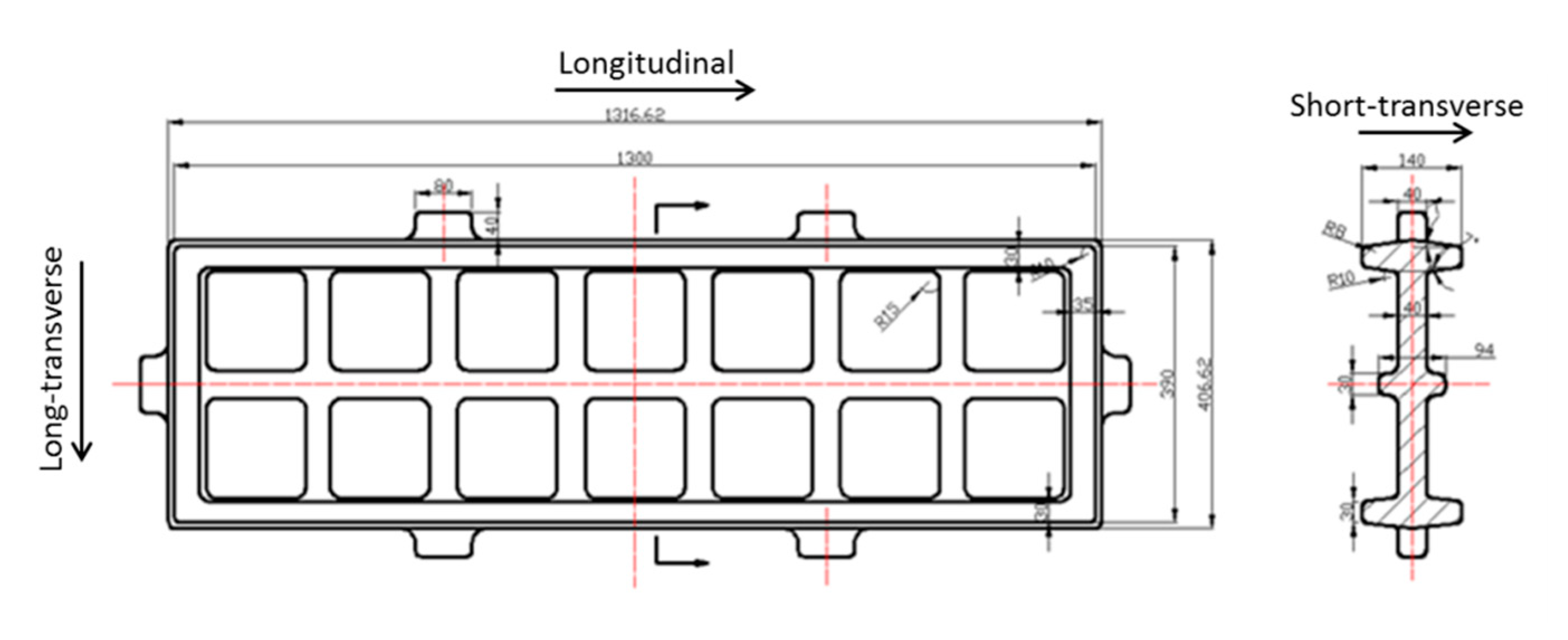
Figure 1, which has a size of 1265 mm×360 mm×130 mm. The roughcast is heated to 420 °C in a box-type heating furnace, and is forged into a die forging with a rib structure by a fire in a 10,000-ton die forging hydraulic press using a special forging mold with a cavity (preheated to 400 °C), as shown in
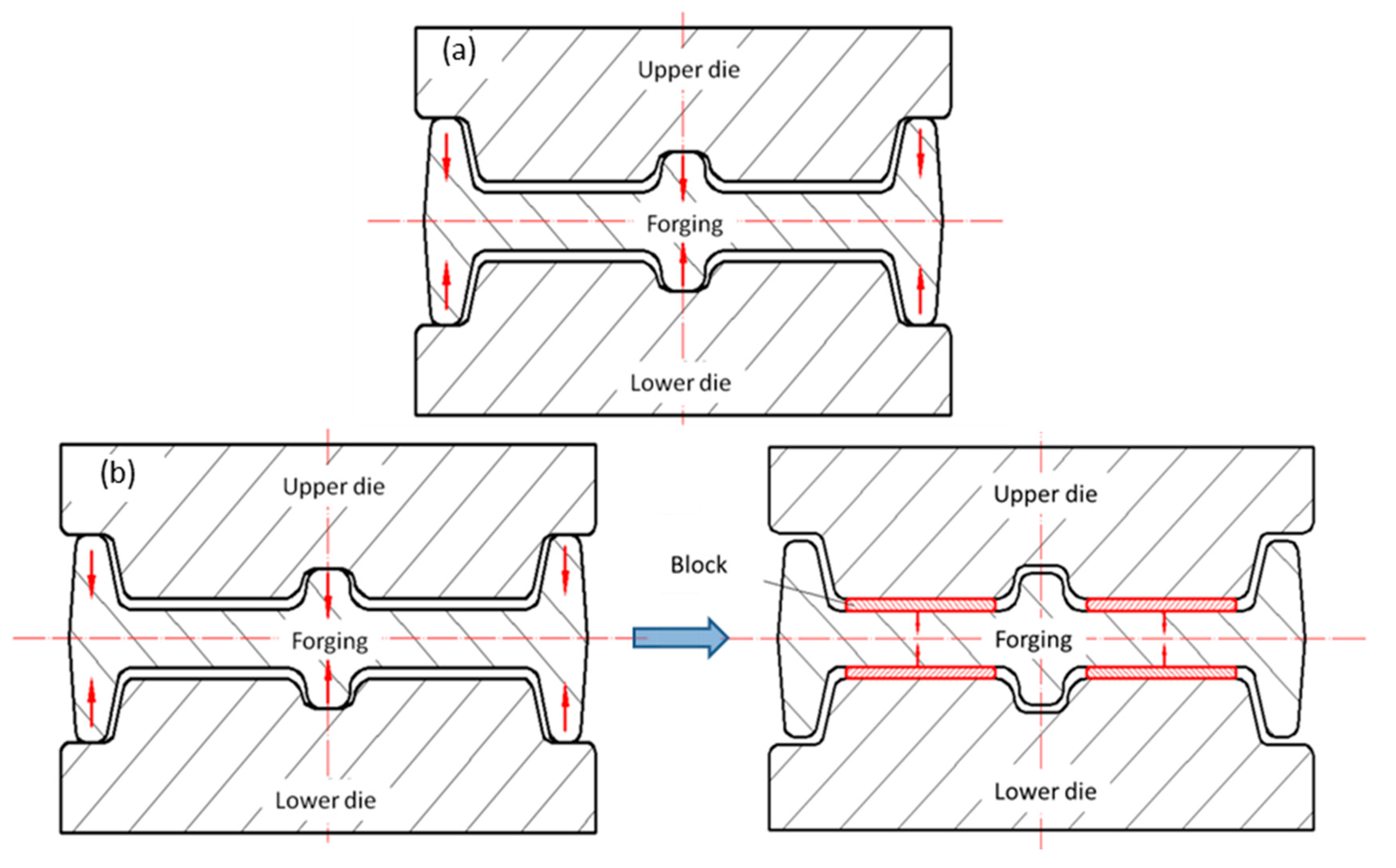
Figure 2. The die forgings were treated by solid solution, quenching, cold compression and double-stage aging treatment to the T7452 state, where the solid solution system was 477 °C/210min+60 °C water quenching, the cold compression amount reference test block result was 2~3%, and the two-stage aging system was 121 °C/6h+177°C/8h. Cold compression is carried out by special cold compression mold, and according to the structural characteristics of die forgings, cold compression is applied to eliminate residual stress by pressing rib and web respectively, as shown in
Figure 3.
The tensile samples are cut from material center and the tension direction is along L direction as shown in
Figure 2. Three samples of room temperature tension are repeated for results accuracy which size is following standard of GB/T 228.1—2021. The fracture toughness is tested according to standard of HB 5487 and the samples are cut from parts along L-T and S-L directions. The conductivity results are tested on the surface of tensile samples and repeated for three times following the standard of GB/T 12966. Transmission electron microscopy (TEM) testing is presented for samples of various compression rate using Philips CM-12 machine, where specimens are prepared by the conditions of -20~30 °C and 15~20V in electrolytic double spray thinning machine.
The residual stresses of the equivalent part and rib-structural forgings is detected by ultrasonic method and blind hole method. Masterscan-380M ultrasonic flaw detector produced by Sonatest is used for ultrasonic testing with a center frequency of 5 MHz and a wafer diameter of Φ 5 inches. During ultrasonic residual stress testing, the sound velocity is changed with material residual stress, and the residual stress is qualitatively obtained according to the change of velocity, where the increase of difference in sound velocity denotes the larger the residual stress [
22]. The blind hole method is tested using ASMB2-32 residual stress detector, and seven positions are selected on the die forgings.
2. Results of Billets
2.1. Mechanical Property of Billets
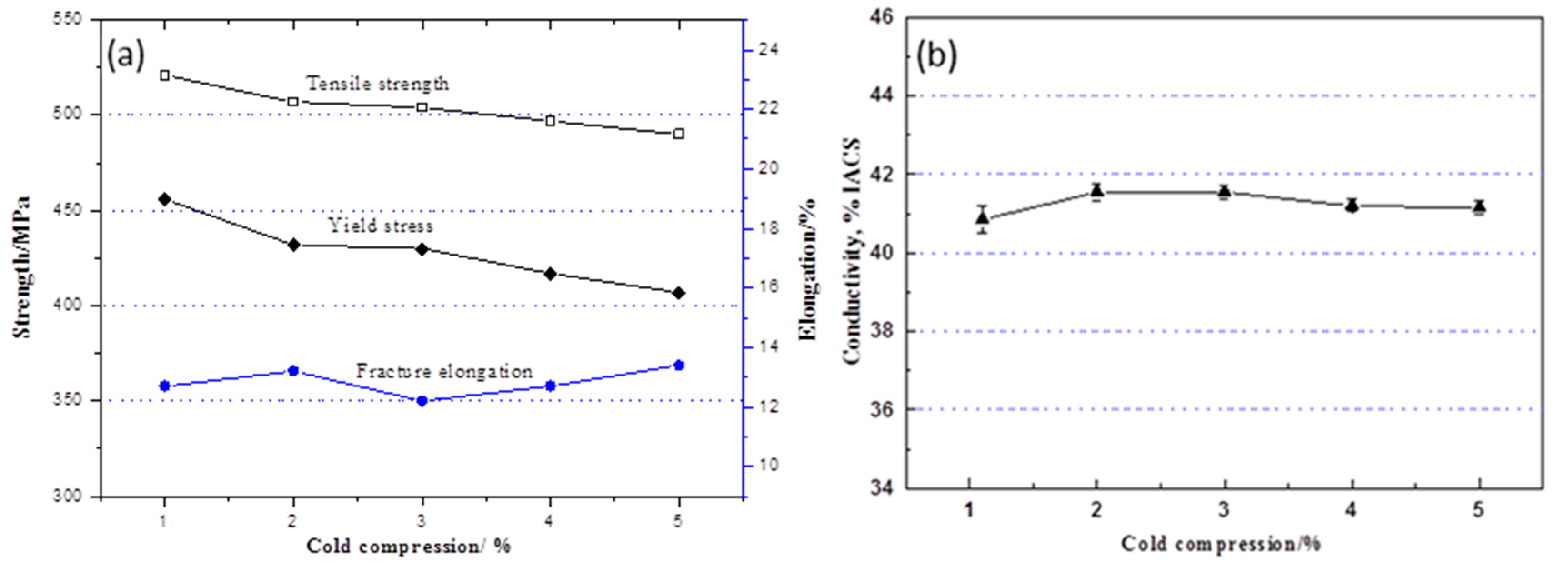
Figure 3 shows the room temperature tensile properties and conductivity of different cold compression rates. As cold compression amount gradually increasing from 1% to 5%, the tensile strength decreases by about 30MPa, and the yield strength decreases by about 50MPa. The elongation of forgings gradually increases. With the increase of cold pressing capacity, the conductivity of forgings changes little.
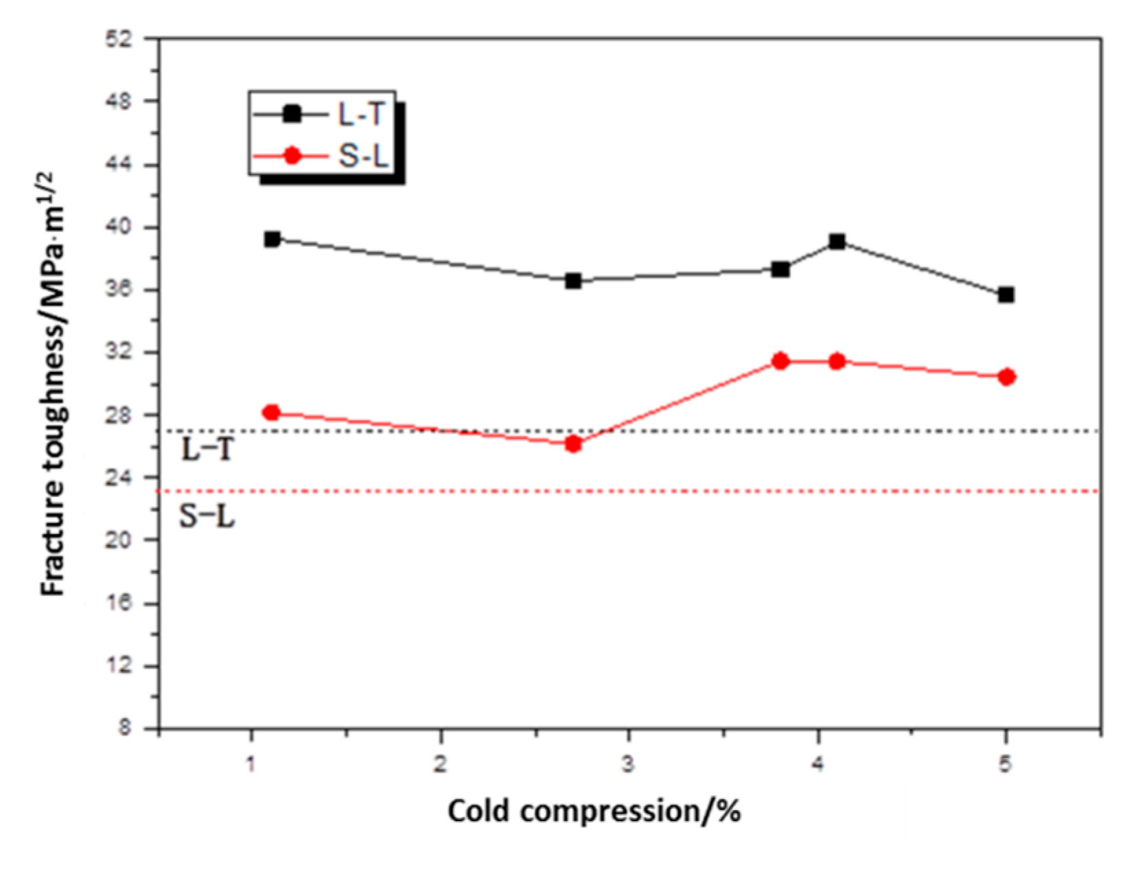
Figure 4 shows the fracture toughness test results. The fracture toughness changes little with the increase of cold compression, and the change value is within 5 MPa·m
1/2.
2.2. Residual Stress of Billets
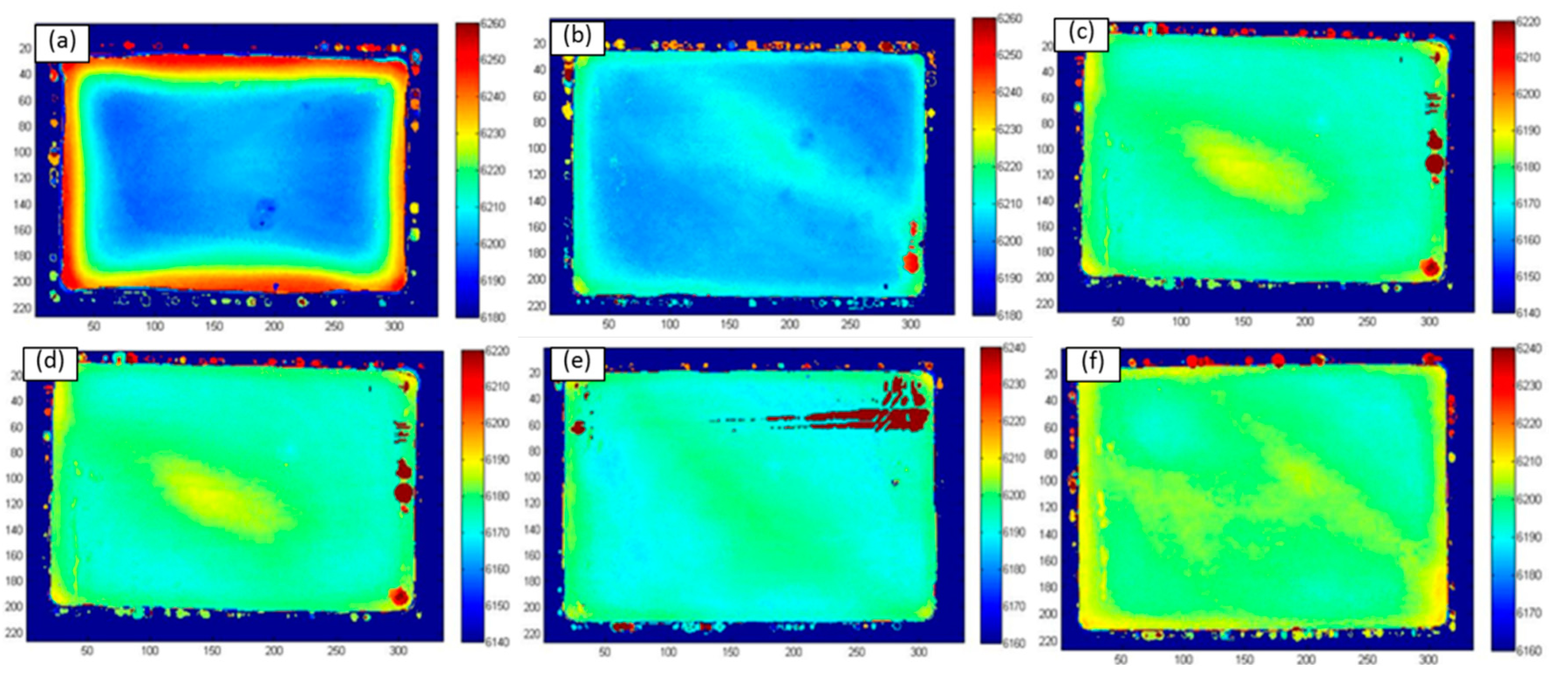
Figure 5 shows the residual stress distribution cloud of different cold compression rates using ultrasound method where the difference in sound velocity is indicated by color difference and residual stress increase with difference. The residual stress is significantly decreased by increasing compression rate.
Figure 5a shows the cloud of the specimen before cold compression, where the large velocity difference between the surface and core indicates the large residual stress difference in the specimen. The presented results are induced by shrinking variation where the outside shrinks quickly while the inside shrinks slowly during quenching, resulting in external tensile stress and internal compressive stress conditions in parts [
23].
Figures 5b–f present cold compression treated specimens where the sound velocity difference is significantly decreased in contract to initial parts, implying a decrease of residual stress after cold compression.
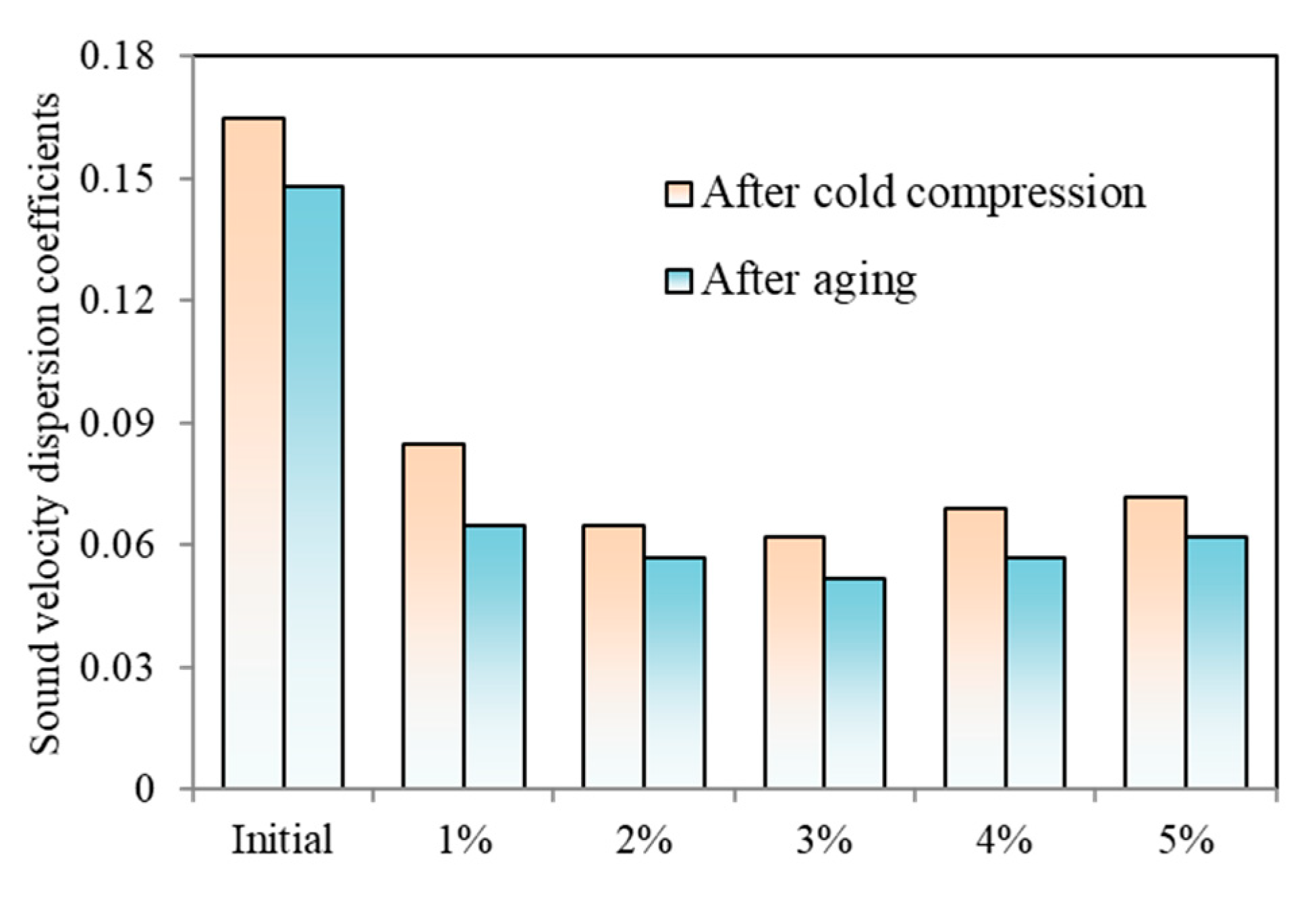
The sound velocity dispersion coefficients of different samples are further obtained to analyze the residual stress qualitatively.
Figure 6 compares the sound velocity difference coefficients with different cold compression and aging processes. The residual stress is decreased first and then reduced with an increase of compression rate. The residual stress is further reduced by aging but keep the variation trend after cold compression. The coefficient of initial sample before cold compression is 0.165 while the coefficient is decreased to 0.085 with 1% compression. As the compression increasing from 1% to 5%, the coefficient is decreased to 0.062 at 3% and then increased to 0.072. The coefficients are further decreased during aging process where the sample without cold compression is decreased to 0.148 while samples with 1%, 3% and 5% are 0.065, 0.052 and 0.062 respectively. Therefore, the suggested compression rate is range from 2% to 4%.
2.3. Microstructure Morphology
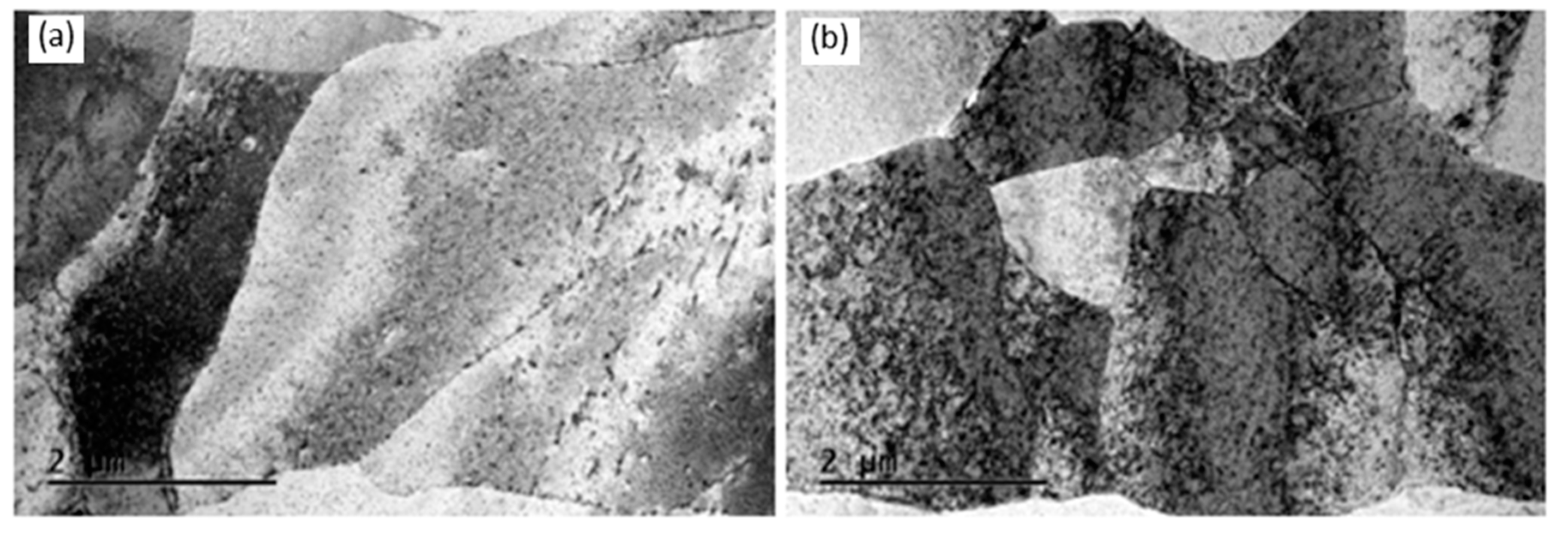
Figure 7 shows the microstructure morphology of material with different cold compression rates. It is shown that the sample with 5% compression rate presents higher dislocation density compared with that with 1% due to the higher plastic deformation inducing dislocation accumulation.
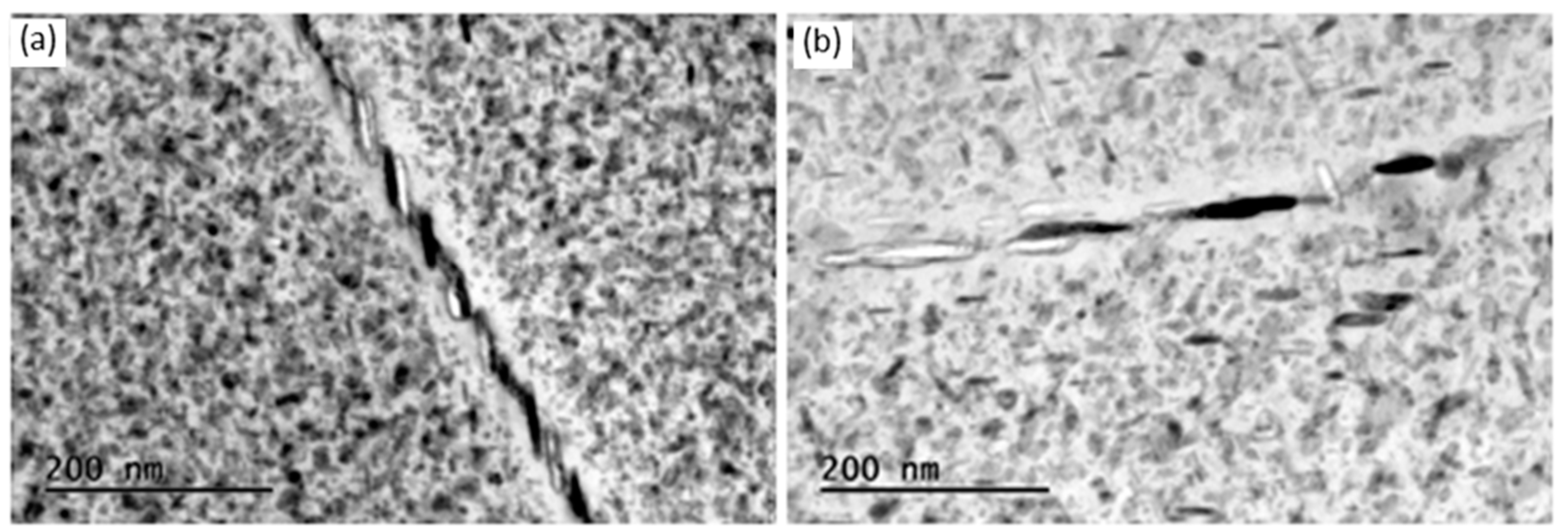
Figure 8 plots the precipitations of samples with various compression rates. The precipitated phase size with the cold compression rate of 5% is significantly larger than that of 1%, because the large energy storage could induce the precipitation and growth of the precipitated phase at the position with high dislocation density during aging process. It is also implied that the cold compression should be uniformed to generate homogeneous precipitated distribution and phase size.
3. Results of Die Forging
3.1. Mechanical Property of Different Cold Compression
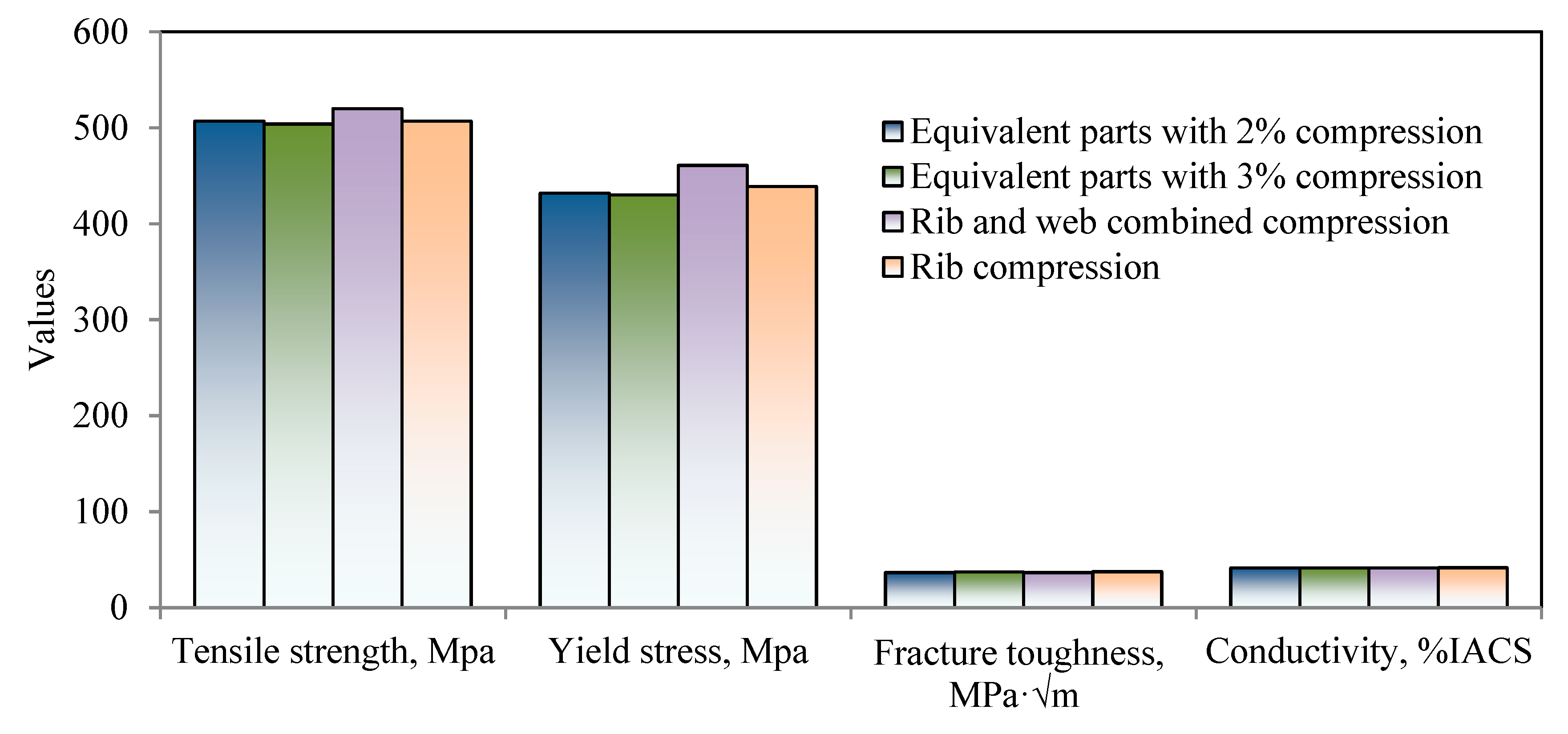
Figure 9 compared the mechanical properties of rib-structural forgings with those of equivalent parts. Two cold compression methods for rib-structural forgings are applied: rib and web combined compression, and rib compression, where cold compression rate of the rib is 2.2% and that of web is 3.1%. It is shown that the mechanical properties of combined compression sample, such as tensile strength, fracture toughness and conductivity, are close to those of equivalent parts with compression rates of 2% and 3%. The tensile strength of rib compression sample is slightly larger than others since its web is not plastically deformed where the strength is decreased with compression rates.
3.2. Residual Stress of Different Cold Compression
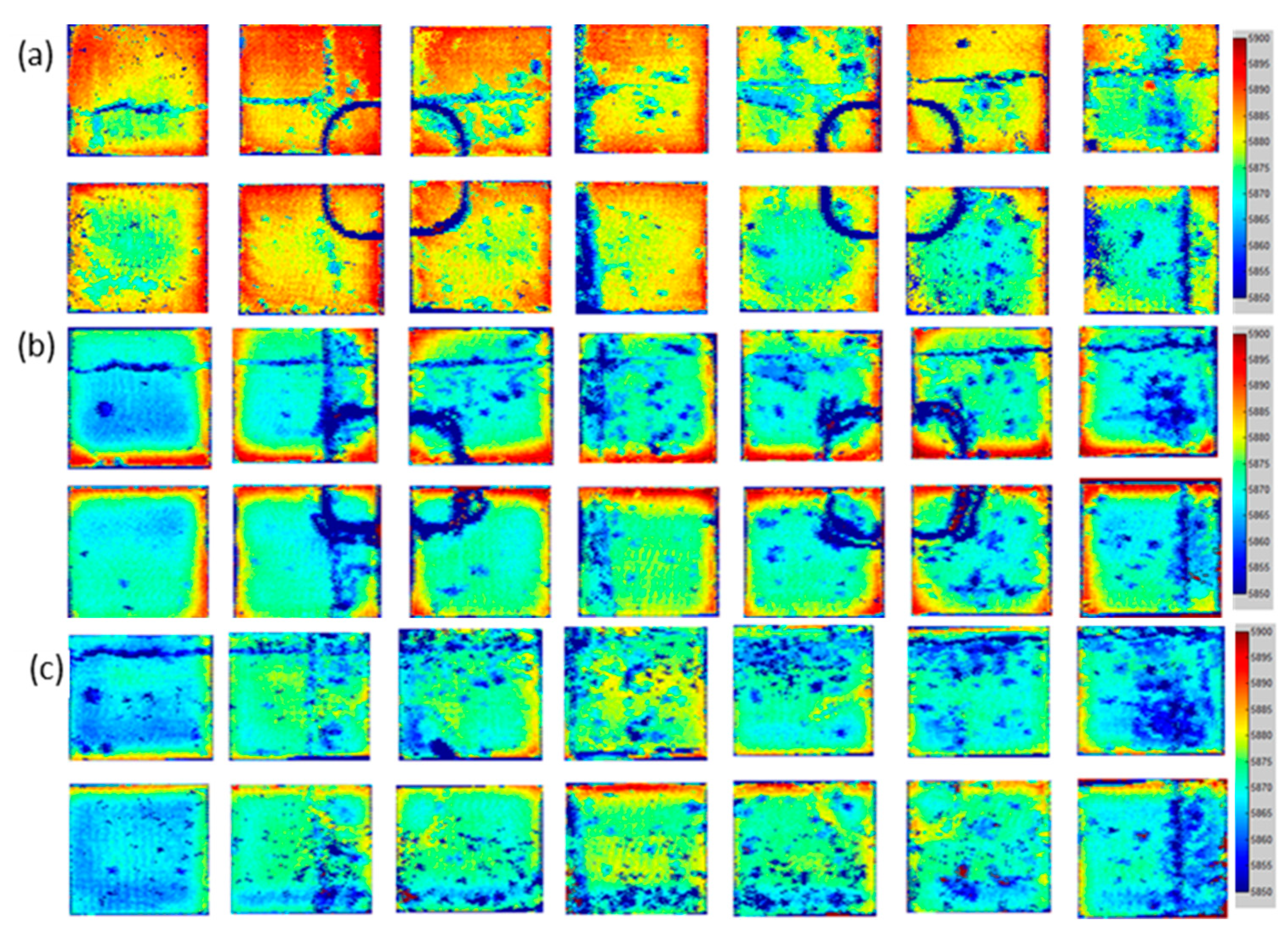
Figure 10 shows the ultrasonic residual stress results of rib-structural forgings of unpressed samples, rib and web combined compression, and rib compression. The unpressed samples show large residual stress, where the stresses at different web position are various due to the rapidly cooling speed at web with 40 mm thickness and the specific cooling direction during quenching process as the part dropped into water.
Figure 10b shows that, for the forgings with rib compression, the material flows to the web during ribs pressing but web is undeformed, so the metal at the root of the ribs is subjected to pressure in two directions and the stress increases, leading to the difference between connection area of web and ribs and the central web is still large.
Figure 10c shows that the residual stress distribution of die forgings with combined compression is relatively uniform, due to the simultaneous deformation of ribs, webs and connection area.
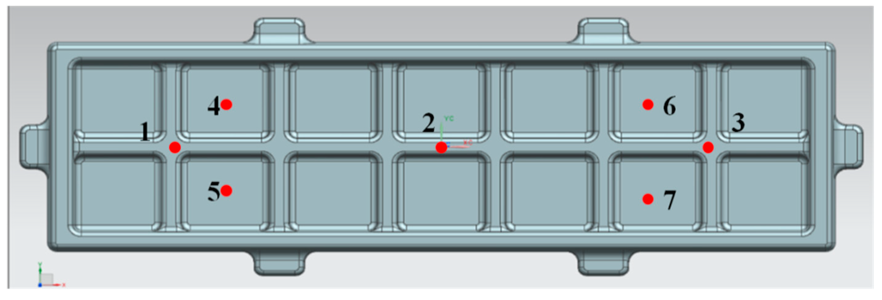
The residual stresses are examined using small hole method and the detected positions are presented in
Figure 11.
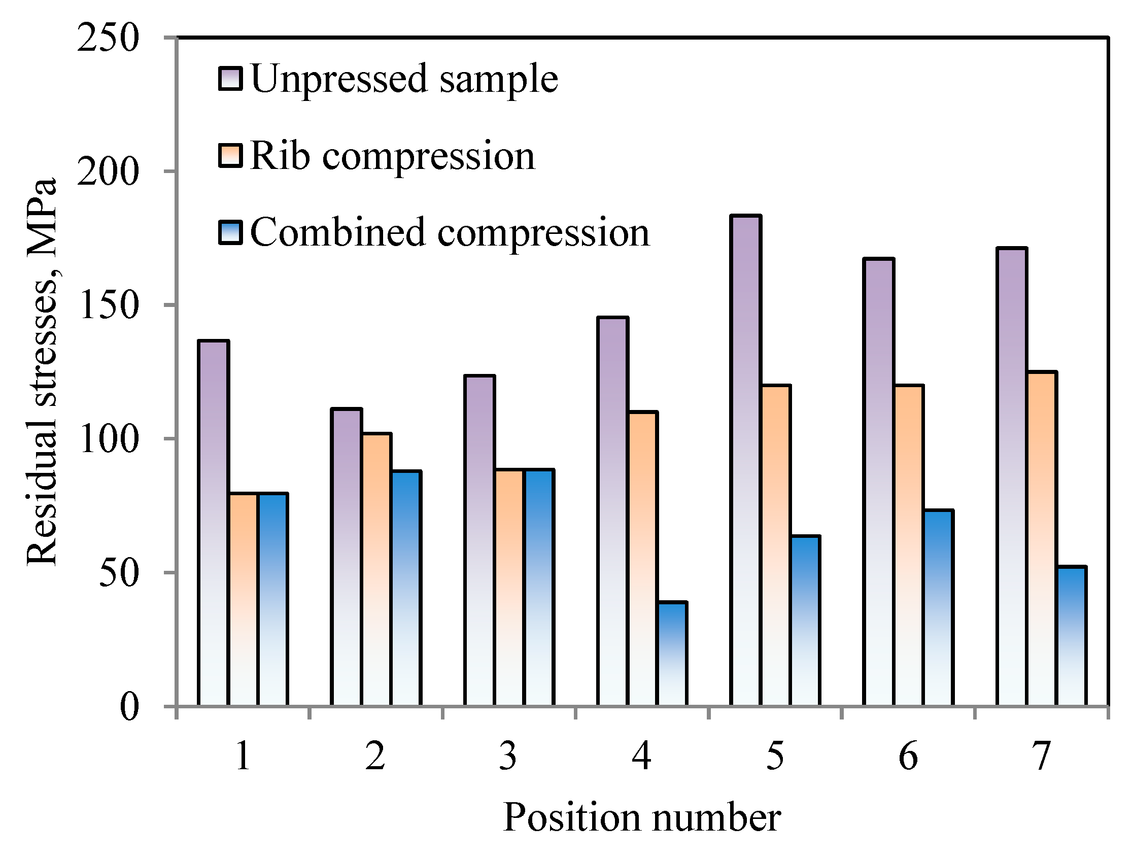
Figure 12 shows the residual stress value of various forging parts where the values of unpressed samples are above 110 MPa, significantly higher than compressed parts. The residual stress is decreased by rib compression method at both of rib and web positions, and its average residual stress is 106.4 MPa which is smaller than 148.4 MPa of initial parts decreased by 28.3%. The rib and web combined compression method decreases the residual stress of web. The average residual stress of rib and web combined compression method is 69.2 MPa which is decreased by 53.3% compared unpressed sample. It is indicated that rib and web combined compression method shows better efficient on residual stress elimination.
3.3. Die Forging Machining Result
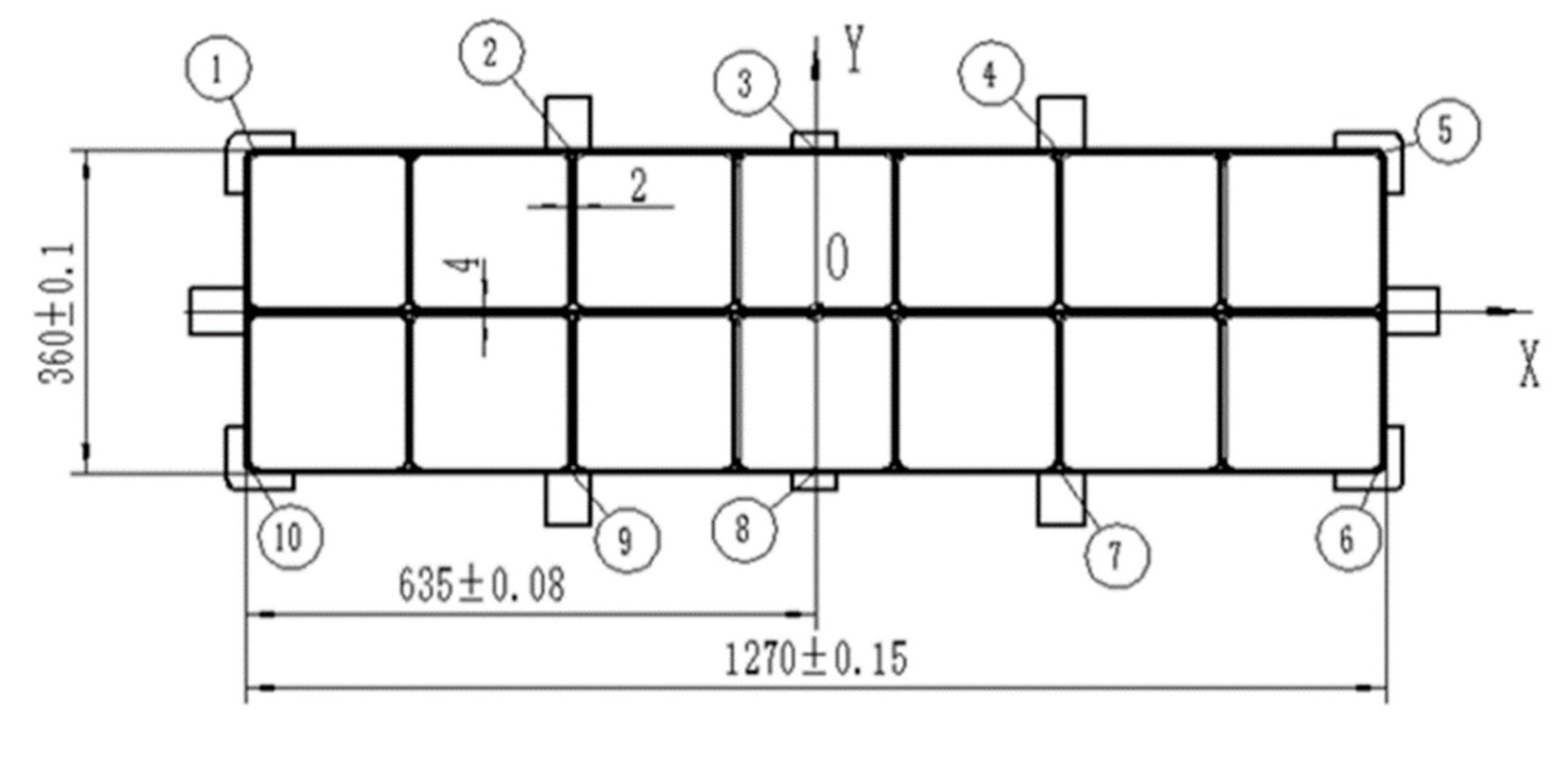
The machining experiment is further carried out and then geometric errors of ten points are measured as shown in
Figure 13.
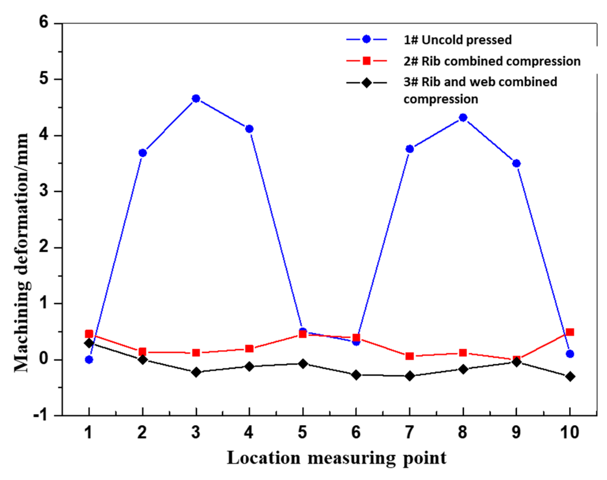
Figure 14 presents the geometric errors of different positions, where the unpressed sample shows a large error at middle of parts with positions of 2~4 and 7~9. The maximum error position is occurred at position 3 and the error is 4.7 mm. The errors are decreased by applying cold compression method implying the decrease of residual stress suppresses the machining deformation. The errors of combined compression method are significantly smaller than those of rib compression method due to the smaller residual stress where the maximum error of combined compression is 0.3 mm while that of rib compression is 0.3 mm. The above results indicate that the rib and web combined compression with compression rate of 2~3% is effective to decrease residual stress and improve geometric accuracy meanwhile keeps the material mechanical properties.
4. Conclusions
Controlling the material residual stress is the key for geometric accuracy of large-scale forging. In this study, the influence of cold compression rate on mechanical properties, residual stress, and geometric error is experimentally investigated using the equivalent part and the aerospace rib-structural parts of aluminum alloy 7050. Meanwhile, the different compression methods are detailed to suggest to recommend methods for complicated-shaped part. This paper provides the suggestive cold compression rate optimizing both properties and residual stresses, and shed the light on industrial applications of cold compression for rib-structural parts. The main summaries are as follows:
(1) The room temperature tensile strength is decreased with the increase of cold compression rate, while the fracture toughness and conductivity changes little. With an increase of cold compression rate, the residual stress is decreased first and then increased, where the optimized cold compression rate is ranged from 2% to 4%.
(2) Increasing the cold compression rate increases the material dislocation density and energy storage, resulting in a promotion of precipitation and growth of the precipitated phase during aging process.
(3) The rib and web combined compression method shows better efficient on decreasing residual stress and improve geometric accuracy in contract to rib compression. Meanwhile, the rib and web combined compression can improve the uniformity of mechanical properties on rib-structural parts.
References
- QIAO H J,LI F G,SUN Y, et al. Simulation of heat treatment process for 7050 high-strength aluminum alloy forging[J]. China Metalforming Equipment & Manufacturing Technology, 2013,48(4):90-93. [CrossRef]
- SUN Y,REN J,ZHANG Y S. Effects of solution and two-step aging on microstructure and hardness of 7050 aluminum alloy[J]. Heat Treatment of Metals, 2016,41(3):25-31. [CrossRef]
- ZANG J X,CHEN G H,FENG Z H. High-temperature mechanical properties and microstructure characteristics of 7A85-T7452 aluminum alloy forgings[J]. Light Alloy Fabrication Technology, 2021,49(7):42-48. [CrossRef]
- ZHANG F Q,YANG Z,YUAN W H, et al.Study on Quenching Residual Stress and Reducing Process of 7050 Aluminum Alloy[J]. Hot Working Technology, 2018,47(24):177-180,185. [CrossRef]
- WAN L,DENG Y LFAN S T. Effects of aging on microstructures, properties and residual stress of 7050 aluminum alloy[J]. The Chinese Journal of Nonferrous Metals, 2018,28(7):1277-1283. [CrossRef]
- HuJianliang, Zhao Zihan, Dong Mengxiao, Microstructure homogeneity regulation of 7050 aluminum forgings by surface cumulative plastic deformation[J]. Transactions of Nonferrous Metals Society of China,2022,32(9):2814-2827. [CrossRef]
- FAN N,XIONG B Q,LI Z H, et al. Influence of pre-stretched ratio on surface residual stress of 7055 aluminum alloy thick plate[J]. The Chinese Journal of Nonferrous Metals, 2020,30(2):301-307. [CrossRef]
- Cold rolling influence on residual stresses evolution in heat-treated AA7xxx T-section panel.
- Assessment of residual stress of 7050-T7452 aluminum alloy forging using the contour method.
- Residual stress in 7449 aluminum alloy forgings.
- Experimental and simulation investigation on thermal-vibratory stress relief process for 7075 aluminum alloy.
- Effect of quenching residual stress on precipitation behaviour of 7085 aluminium alloy.
- YAO S J,XIA W J,YUAN W H, et al. Residual Stress Reduction of 7050 Large-Scale Aluminum Alloy Forging Based on Segmented Cold-Pressing Method[J]. Materials for Mechanical Engineering, 2018,42(1):84-88. [CrossRef]
- NIU G M,LI W,WANG J Q, et al. Investigation on Residual Stress Evolution of 7085 Aluminum Alloy Free Forging Plate after Quenching-Subsection Cold Pressing[J]. Hot Working Technology, 2019,48(3):140-144. [CrossRef]
- PAN, RAN, SHI, ZHUSHENG, DAVIES, CATRIN M., et al. An integrated model to predict residual stress reduction by multiple cold forging operations in extra-large AA7050 T-section panels[J]. Proceedings of the Institution of Mechanical Engineers, Part B. Journal of engineering manufacture,2018,232(8):1319-1330. [CrossRef]
- An analytical model to predict the machining deformation of frame parts caused by residual stress.
- Integrated physically based modeling for the multiple static softening mechanisms following multi-stage hot deformation in Al-Zn-Mg-Cu alloys.
- The kinetics of dynamic and static softening during multistage hot deformation of 7150 aluminum alloy.
- Static softening following multistage hot deformation of 7150 aluminum alloy: Experiment and modeling.
- WU X W,WU D X,XU K C. Research on quenching residual stress reduction technology for 7050 aluminum alloy long-axis reinforced plate rorgings [J]. Aluminium Fabrication, 2021(4):27-30. [CrossRef]
- ZHAI R Z,YIN H,TENG S M, Study on Quenching Residual Stress Reduction of Large Free Forgings of Aluminum Alloy 7050[J]. Heavy Casting and Forging, 2022(4):56-58,65. [CrossRef]
- WANG X,LI G A,LI H Q, et al.Analytical Method on Residual Stress in Aluminum Alloy Based on Self-balancing Feature by Using Ultrasonic [J]. Hot Working Technology 2022,51(6):56-61. [CrossRef]
- WANG H,XIAO N M,LI H Q, et al. Simulation study on reducing residual stress of 7050 aluminum alloy by cold deformation process[J]. Die and Mould Technology, 2021(1):1-7. [CrossRef]
Figure 2.
aluminium alloy die forging dimensions.
Figure 2.
aluminium alloy die forging dimensions.
Figure 3.
Cold compression of die forging (a) Reinforcement bar, (b) Press bar and press web.
Figure 3.
Cold compression of die forging (a) Reinforcement bar, (b) Press bar and press web.
Figure 3.
Tensile property and conductivity curves of different cold pressure, (a) Tensile properties, (b) Conductivity.
Figure 3.
Tensile property and conductivity curves of different cold pressure, (a) Tensile properties, (b) Conductivity.
Figure 4.
Fracture toughness curves of different cold pressure.
Figure 4.
Fracture toughness curves of different cold pressure.
Figure 5.
Contour maps of different cold compression , (a)Uncold pressed, (b)Cold compression 1%, (c)Cold compression 2%, (d)Cold compression 3%, (e)Cold compression 4%, (f)Cold compression 5%.
Figure 5.
Contour maps of different cold compression , (a)Uncold pressed, (b)Cold compression 1%, (c)Cold compression 2%, (d)Cold compression 3%, (e)Cold compression 4%, (f)Cold compression 5%.
Figure 6.
Sound velocity dispersion coefficients.
Figure 6.
Sound velocity dispersion coefficients.
Figure 7.
Microstructure morphology of dislocation, (a) Compression rate of 1%, (b) Compression rate of 5%.
Figure 7.
Microstructure morphology of dislocation, (a) Compression rate of 1%, (b) Compression rate of 5%.
Figure 8.
Morphology of grain boundary precipitated phase, (a) Compression rate of 1%, (b) Compression rate of 5%.
Figure 8.
Morphology of grain boundary precipitated phase, (a) Compression rate of 1%, (b) Compression rate of 5%.
Figure 9.
Comparison of mechanical properties between die forging and billets.
Figure 9.
Comparison of mechanical properties between die forging and billets.
Figure 10.
Ultrasonic residual stress test results, (a)Unpressed samples, (b) Rib combined compression, (c) Rib and web combined compression.
Figure 10.
Ultrasonic residual stress test results, (a)Unpressed samples, (b) Rib combined compression, (c) Rib and web combined compression.
Figure 11.
Residual stress detection points.
Figure 11.
Residual stress detection points.
Figure 12.
Residual stress comparison results of die forging.
Figure 12.
Residual stress comparison results of die forging.
Figure 13.
Location measuring point for die forging.
Figure 13.
Location measuring point for die forging.
Figure 14.
Machining deformation of die forging parts.
Figure 14.
Machining deformation of die forging parts.
Table 1.
The manufacture process parameters.
Table 1.
The manufacture process parameters.
| Process |
Parameters |
Size/mm |
| Solution and quenching |
477℃, 60℃ of water |
200 (L)×150 (LT)×140 (ST) |
| Cold compression |
1%, 2%, 3%, 4%, 5% |
| Aging process |
121℃×6h+177℃×8h |
|
Disclaimer/Publisher’s Note: The statements, opinions and data contained in all publications are solely those of the individual author(s) and contributor(s) and not of MDPI and/or the editor(s). MDPI and/or the editor(s) disclaim responsibility for any injury to people or property resulting from any ideas, methods, instructions or products referred to in the content. |
© 2023 by the authors. Licensee MDPI, Basel, Switzerland. This article is an open access article distributed under the terms and conditions of the Creative Commons Attribution (CC BY) license (http://creativecommons.org/licenses/by/4.0/).

