Preprint
Article

CO2 Injection for Enhanced Gas Recovery and Geo-Storage in Complex Tight Sandstone Gas Reservoirs

Altmetrics

Downloads

158

Views

63

Comments

0

A peer-reviewed article of this preprint also exists.

Submitted:

31 May 2023

Posted:

31 May 2023

You are already at the latest version

Alerts
Abstract
With the popularization of natural gas and the requirements for environmental protection, the development and utilization of natural gas is particularly important. The status of natural gas in China's oil and gas exploration and development is constantly improving, and the country is paying more and more attention to the exploitation and utilization of natural gas. The Upper Paleozoic tight sandstone in the Ordos Basin is characterized by low porosity, low permeability and large area of concealed gas reservoirs. By injecting CO2 into the formation, the recovery of natural gas can be improved, and at the same time, the stable storage of CO2 can be achieved to achieve a win-win situation of CO2 emission reduction and utilization. Injecting greenhouse gas CO2 into gas reservoirs for storage and improving recovery has also become a hot research issue. In order to improve the recovery efficiency of tight sandstone gas reservoir, this paper takes the complex tight sandstone of Upper Paleozoic in Ordos Basin as the research object, through indoor physical simulation experiments, carried out the influence of displacement rate, fracture dip angle, core permeability, core dryness and wetness on CO2 gas displacement efficiency and storage efficiency, and analyzed the influence of different factors on CO2 gas displacement efficiency and storage efficiency to improve the recovery and storage efficiency. The research results show that under different conditions, when the CO2 injection pore volume is less than 1PV, the relationship between the CH4 recovery rate and the CO2 injection pore volume is linear, and the tilt angle is 45 °. When the CO2 injection pore volume exceeds 1PV, the CH4 recovery rate increases slightly with the increase of displacement speed, the recovery rate of CO2 displacement CH4 is between 87% - 97%, and the CO2 breakthrough time is 0.7PV-0.9PV. In low-permeability and low-speed displacement cores, the diffusion of CO2 molecules is more significant. The lower the displacement speed is, the earlier the breakthrough time of CO2 is, and the final recovery of CH4 slightly decreases. Gravity has a great impact on CO2 storage and enhanced recovery. The breakthrough of high injection and low recovery of CO2 is earlier, and the recovery of CH4 is about 3.3% lower than that of low injection and high recovery. The bound water makes the displacement phase CO2 partially dissolved in the formation water, and the CO2 breakthrough lags about 0.1PV. Ultimately, CH4 recovery factor and CO2 storage rate are higher than those of dry core displacement. The research results provide theoretical data support for CO2 injection to improve recovery and storage efficiency in complex tight sandstone gas reservoirs.
Keywords: 
Subject: Engineering  -   Other

1. Introduction

With the rapid development of the industrial society, the burning of a large amount of fossil fuels in human activities has led to the emission of a large amount of carbon dioxide into the atmosphere, resulting in global warming and a serious threat to people's living environment [1,2,3,4]. By sequestering carbon dioxide, reducing CO2 emissions in the atmosphere has become an important way to slow down global warming and climate change [5]. CO2 geological storage is a technically feasible, efficient emission reduction, safe and environmentally friendly solution. Common sites for CO2 geological storage include deep brine formations, depleted oil and gas reservoirs, unminable coal seams, and deep-sea projects. If CO2 is simply stored, the cost is high [6]. Therefore, the large-scale utilization of CO2 greenhouse gas by improving oil and gas recovery while storage has become a hot research topic. At present, the Ordos Basin, Tarim Basin, and Luangehai Basin in China have abundant natural gas reserves, and the storage potential of CO2 is also huge [7]. Since the gas reservoir itself exists in the natural geological body that is most suitable for storing gaseous substances, the gas storage and sealing properties of the gas-bearing reservoir have also been fully confirmed in the natural gas occurrence and development stage [8]. The implementation of CO2 storage has theoretical and practical advantages practical feasibility. The existing results show that CO2 is very unlikely to be stored in the form of gas, and the supercritical state has the greatest storage potential in the formation [9,10]. Gas reservoirs whose formation temperature and pressure exceed the critical point of CO2 are the most suitable sites for CO2 storage. Therefore, from the perspective of economic benefits, it is a hot research topic to achieve enhanced natural gas recovery by injecting CO2 into gas reservoirs and using its own conditions for storage [11].
Some research results have been achieved on the implementation of CO2 storage in natural gas reservoirs and the use of supercritical CO2 to enhance natural gas recovery [12]. Some researchers have carried out basic research on CO2 enhanced recovery and storage technology, and simplified natural gas into pure CH4 [13]. When the temperature and pressure of gas reservoirs with a depth of more than 800m exceed the CO2 critical point, CO2 can be in a supercritical state and exists underground, and at the same time its supercritical density is higher than that of natural gas, close to liquid, with a certain strength, the diffusion coefficient is close to that of gas, about 100 times that of liquid, and it has good fluidity. Some researchers use CO2 storage to increase oil and gas recovery, mainly by injecting CO2 into production wells to displace oil or gas [14]. It has been proved that CO2 displacement technology can prolong the life of oilfields by at least 20 years. Combined with oil displacement technology, it greatly improves the profit of mining [15,16]. Some researchers have studied the potential of gas injection to enhance oil recovery in major oil areas in China. The 17 oil areas suitable for CO2 miscible displacement have 1.6× 10 8 t of geological reserves, accounting for 10.4% of the total reserves. The enhanced oil recovery rate is 16.4%, and the recoverable reserves are increased by 1.7× 10 8 t. At the same time, it proves that China's oil reservoirs have considerable potential for CO2 geological storage [17]. Some researchers take long core as the research object, through indoor experiments and numerical simulation methods, inject supercritical CO2 into the condensate gas reservoir circularly to obtain higher condensate oil recovery and obtain a large number of components [18]. This is mainly due to the reverse evaporation of heavy components into the CO2 condensate gas mixture caused by thermal gradient. With the increase of temperature, the formation fluid flow rate increases, which increases the gas phase viscosity and decreases the liquid phase viscosity, promotes the thermal diffusion, increases the dissolution effect of CO2, and enhances the reverse evaporation intensity to improve its recovery [19]. Some researchers have studied the cyclic gas injection test in the fractured gas reservoir. By injecting different gases into a fractured core and conducting long core physical simulation experiments, they found that the injection timing and the composition of injected gas are two key parameters to achieve miscible gas [20,21,22]. The miscible gas injected into the condensate gas reservoir has obtained greater condensate recovery. At the same time, the existence of fracture system near the matrix is more conducive to the depletion of pressure in the matrix and the recovery of more condensate. When injecting gas under miscible and immiscible pressures, it can be observed that the higher the injection pressure, and the less the condensate content in the matrix core, and the greater the condensate recovery [23].
The complex tight sandstone has the characteristics of low porosity, low permeability, and a large area of concealed gas reservoirs [24,25]. By injecting CO2 into the formation, the recovery rate of natural gas can be improved, and the stable storage of CO2 can be achieved at the same time [26]. In this paper, taking the complex and tight sandstone of the Upper Paleozoic in the Ordos Basin as the research object, through laboratory physical simulation experiments, the effects of displacement rate, fissure dip, core permeability, core dry and wet on CO2 displacement efficiency and storage efficiency were carried out [27]. The effects of different factors on CO2 displacing efficiency and storage efficiency are analyzed, which provides theoretical data support for CO2 injection in complex tight sandstone gas reservoirs to improve recovery and storage efficiency [28].

2. Experimental methods

2.1. Geological background of the study area

The Ordos Basin is located in the west-central part of China. The basin is generally rhombus-shaped, extending from north to south. It is adjacent to Yinshan and Daqingshan in the north, Qinling Mountains in the south, Luliang Mountain in the east, and Liupan Mountain in the west. This paper selects the tight sandstone reservoirs in the Hangjinqi area of the Ordos Basin. The recoverable positions of natural gas in the study area are Carboniferous and Permian, including Lower Shihezi Formation, Upper Shihezi Formation and Shiqianfeng Formation. Table 1 shows the specific characteristics of each stratum in the study area. The lithology of Lower Shihezi Formation and Upper Shihezi Formation are relatively diverse, and the coal seams and mudstones have strong hydrocarbon generation capacity, providing good source rock conditions for the formation of natural gas reservoirs in this area. Sandstone and glutenite developed in Shiqianfeng Formation have relatively good reservoir properties, providing good reservoir conditions and good cap rock conditions for gas accumulation.

2.2. Experimental scheme

The tight sandstone cores in the study area are selected and divided into 10 groups of CO2 displacement CH4 experiments. The displacement velocities are set as 0.1ml/min, 0.2ml/min, 0.4ml/min and 0.8ml/min respectively. The injection end dip angles are 45°, -10°, -45° and nearly horizontal. For cores with low, medium and high permeability, the permeability respectively are 2.18✕10-3 μm2, 9.66✕10-3 μm2, 1.03✕10-1μm2 and the influence group whether there is bound water is set up. Study the influence of core permeability, gas injection rate, the existence of formation water and gravity on the gas displacement efficiency and storage efficiency when CO2 displaces CH4, and evaluate the diffusion degree of CO2-CH4 under different influence factors. Table 2 shows the experimental schemes for different cores.
In the experiment, the core displacement equipment of RUSKA Company in the United States was used, mainly including injection system, core clamping system and recovery system. The auxiliary equipment mainly includes constant pressure and constant speed displacement pump, gas meter and gas chromatograph. Table 3 shows the composition of formation water samples in the experiment, mainly including industrial high-purity CO2 (molar concentration>99.9%) and high-purity CH4 (molar concentration>99%). The formation water is prepared according to the ion content and salinity of the on-site formation water.
All cores in the experiment are divided into three groups. Formation sampling and artificial cores are divided into relatively high permeability, medium permeability and low permeability. At present, the drilling core technology is limited, and it is impossible to directly obtain cores with a length of 1 m. During the experimental test, the temperature is realized by multiple sets of heating plates in the incubator, and the pressure is monitored by the measured electronic pressure gauge. The high-pressure corrosion-resistant rubber sleeve is installed in the core holder for sealing. Table 4 shows the physical parameter information table of low-permeability cores, and the cores are sorted from exit to entry and from top to bottom.

2.3. Experimental conditions and steps

In the experiment, the core temperature is set to 80 ℃, the pressure is set to 8MPa (controlled back pressure), and constant speed displacement is adopted. The experimental steps are:
(1) Put the short core into the long core holder in sequence, put it into the thermostat according to the angle of the injection end and connect the displacement device;
(2) Add 10MPa confining pressure to the core, limit the maximum pressure to 5MPa at the speed of 5ml/min through the advection pump, and use the mixture of displacing petroleum ether and anhydrous ethanol to clean the long core until the outlet fluid is free of discoloration and impurities;
(3) Use nitrogen to drive long core at 2MPa constant pressure for 12h, and vacuum the long core after drying for 5h;
(4) Fill saturated high-purity CH4 gas, increase the core confining pressure to 12MPa, use constant pressure 8MPa to saturate CH4, and close the outlet valve port; when the inlet pressure reaches 8 MPa and maintains for 4 hours, CH4 saturation can be considered as complete;
(5) Connect the high-purity CO2 intermediate container, drive CH4 in the core at the design speed, set the back pressure to 8MPa, record the gas volume every 0.1PV, and test the composition of the produced gas; use gas chromatograph to analyze CH4 and CO2 content to calculate CH4 recovery rate; when the CO2 content reaches more than 98% or the CH4 recovery rate no longer increases, the displacement is stopped and the experiment is completed;
(6) After the experiment, vacuum the core again and saturate CH4 to conduct the next group of displacement experiments;
(7) By changing the angle of long core gripper, high injection low production or low injection high production with different dip angles can be realized.

3. Experimental results and analysis

3.1. Test results

According to the designed experimental scheme, the experiments were carried out under the conditions of 80 °C and 8MPa with CO2 displacement rates of 0.1ml /min, 0.2ml /min, 0.4ml /min and 0.8ml /min on the permeability of saturated high-purity CH4. The cores were displaced, and the effects of different displacement rates, different dip angles, different permeability cores, and dry and wet cores on CO2 storage efficiency were analyzed.
Figure 1 shows the change of core CH4 recovery with CO2 injection pore volume under different displacement velocities. It can be seen from Figure 1 that when the CO2 injected pore volume is less than 1PV, the relationship between the CH4 recovery factor and the CO2 injected pore volume is linearly correlated, and the inclination angle is 45°; when the CO2 injected pore volume exceeds 1PV, the recovery factor of CH4 increases slightly with the increase of displacement speed; when the displacement rate is 0.8ml / min, compared with the displacement rate of 0.1ml /min, the CH4 recovery rate is about 8% higher, and the final recovery rate is 2.7% higher.
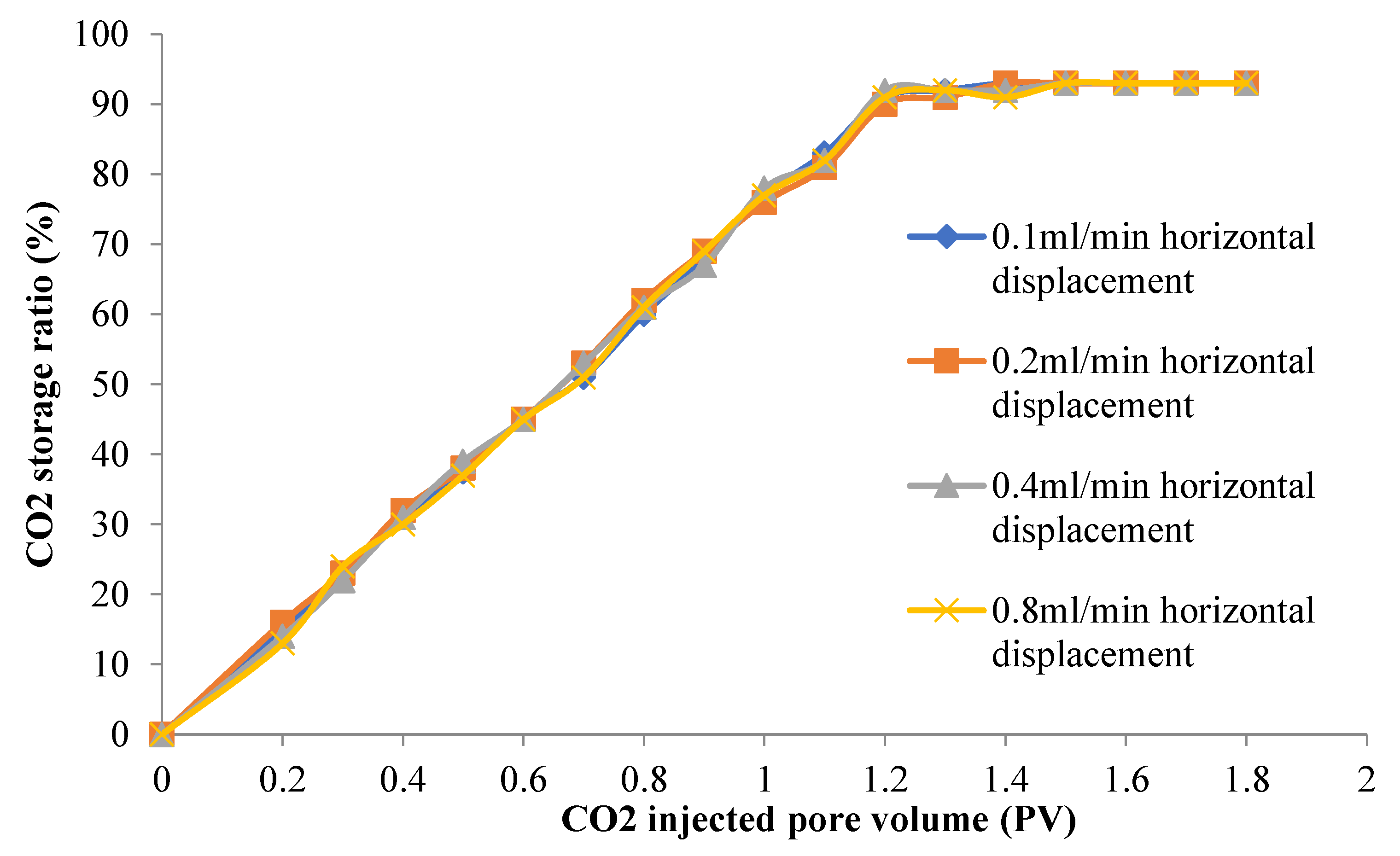
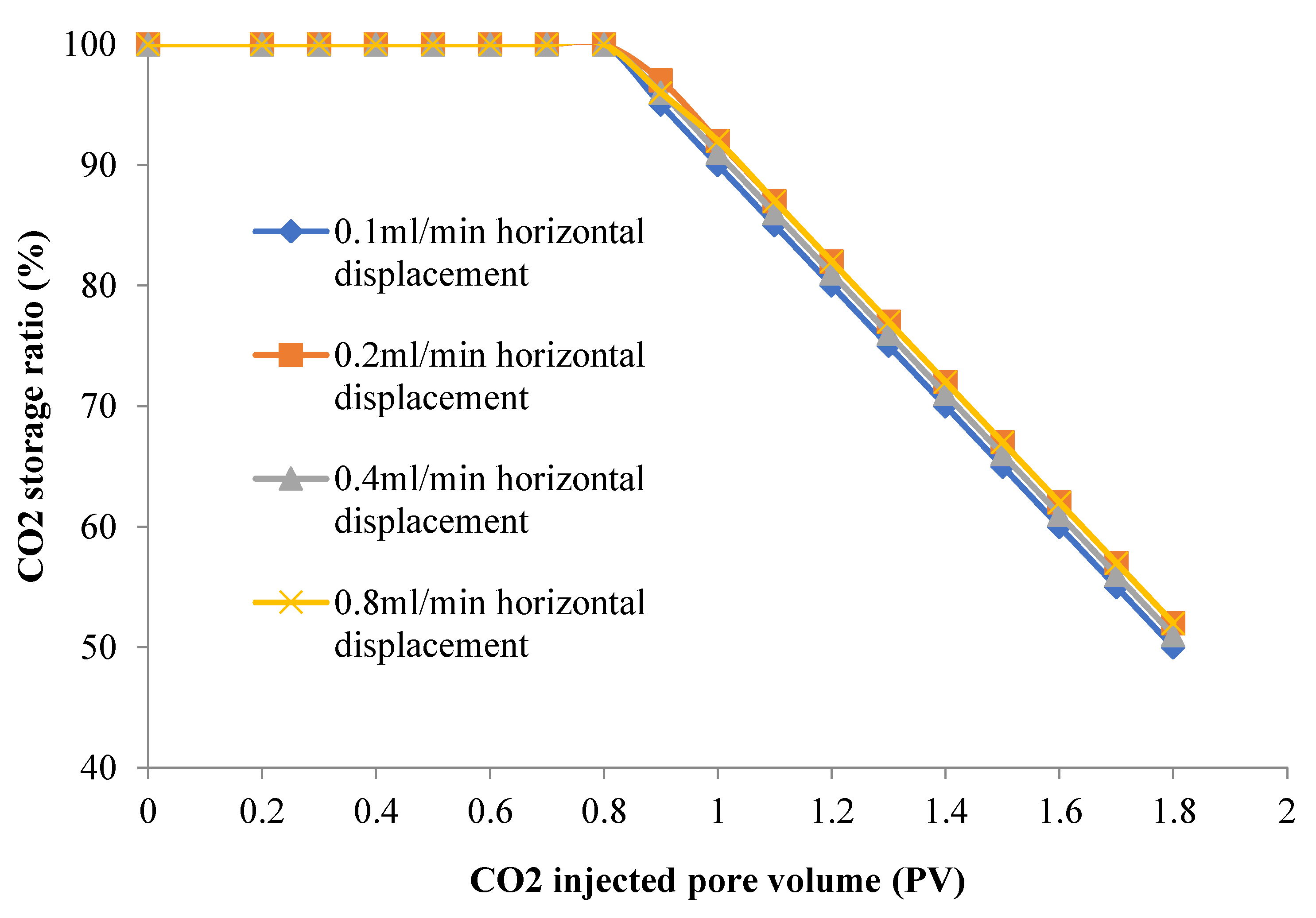
The CO2 storage rate refers to the ratio of the CO2 storage amount to the core pore volume, and the CO2 storage ratio refers to the ratio of the CO2 storage amount to the total amount of CO2 injected. The CO2 storage efficiency under different experimental conditions was studied by calculating the CO2 storage rate and storage ratio. Figure 2 shows the relationship between the CO2 storage rate of the core and the injected pore volume under different displacement rates. It can be seen from Figure 2 that before CO2 breakthrough, the CO2 storage efficiency increases in a 45° oblique line. After the CO2 breakthrough, the smaller displacement rate makes the CO2 storage rate increase slowly, which indicates that the mixing time of CO2 front and CH4 is longer, and the transition zone is wider. When the CO2 breakthrough, the CO2 storage rate decreases, and the final CO2 storage rate under different displacement rates is consistent. Figure 3 shows the relationship between the CO2 storage ratio and the injected pore volume in the core under different displacement rates. It can be seen from Figure 3 that with the continuous injection of CO2, the initial storage ratio of CO2 is 100%, but when the CO2 breakthrough, the storage ratio will gradually decrease. When the CO2 injection exceeds 1PV, under the same PV number, the rate of CO2 storage at different displacement speeds is basically consistent.
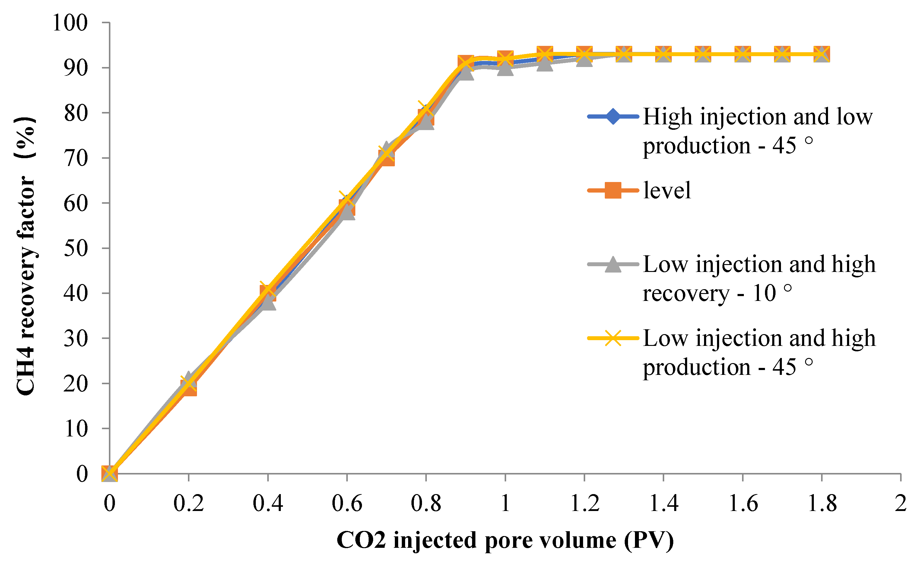
Figure 4 shows the relationship between CH4 recovery rate of core and CO2 injection pore volume under different displacement angles. It can be seen from Figure 4 that the CH4 recovery factor is linearly related to the injected pore volume, and the inclination angle is 45 °. At the same time, when CO2 breakthrough occurs, the CH4 recovery factor (76%) of high injection and low recovery is 11% lower than that of low injection and high recovery. The higher the outlet end is, the greater the recovery factor will be.
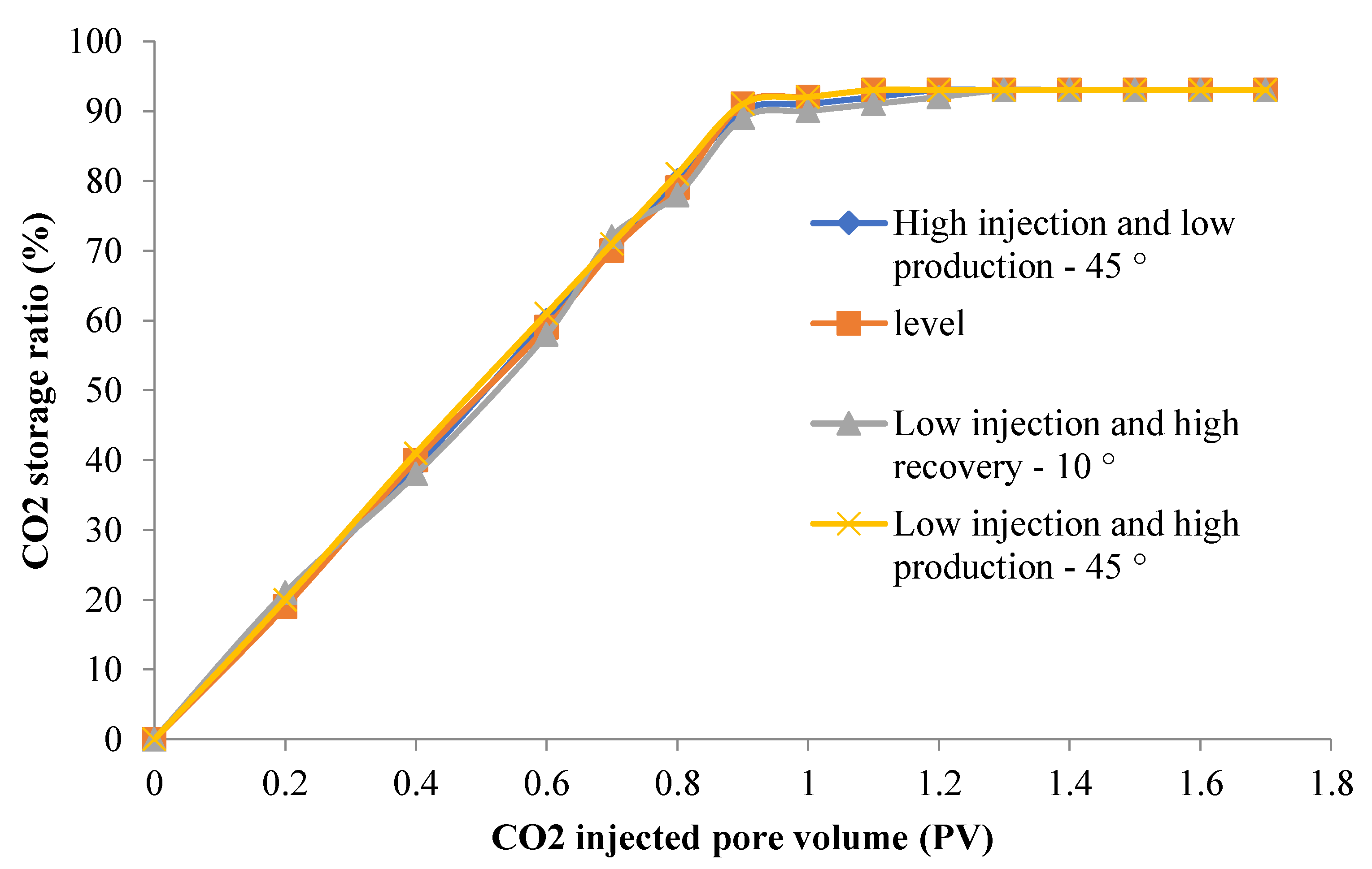
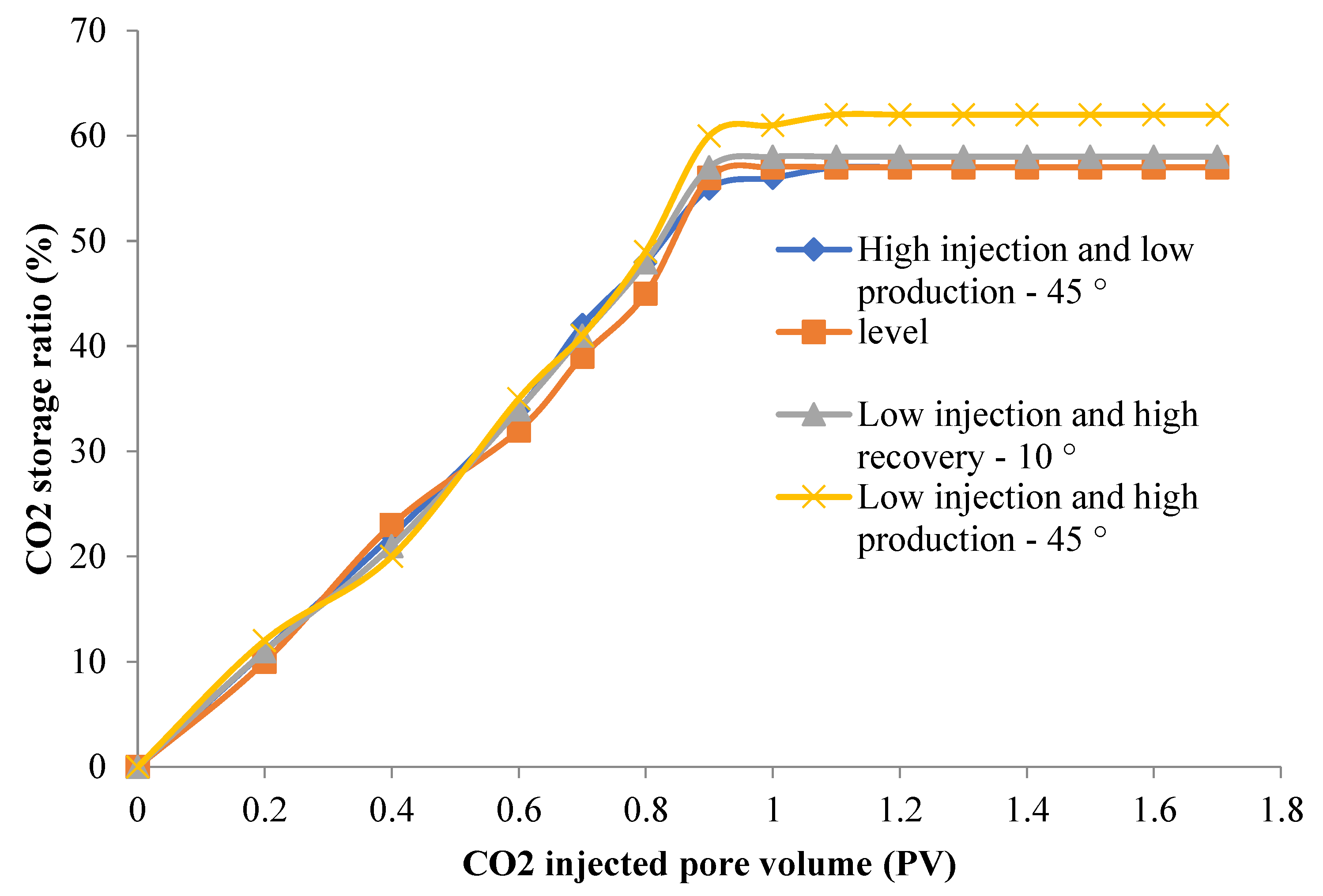
Figure 5 shows the relationship between CO2 storage rate and injected pore volume in cores under different displacement angles. It can be seen from Figure 5 that before the CO2 breakthrough, the CO2 storage rate increases in a 45 ° oblique straight line. After the CO2 breakthrough, the growth rate of CO2 storage rate slows down. At the same time, because the breakthrough of high injection and low production is earlier, the final CO2 storage rate is lower than that of horizontal displacement and low injection and high production. Figure 6 shows the relationship between the buried proportion of CO2 in the core and the injected pore volume under different displacement velocities. It can be seen from Figure 6 that with the continuous injection of CO2, the storage ratio of CO2 at the initial stage is 100%, but after the breakthrough of CO2, the storage ratio of CO2 will gradually decrease. After the injection exceeds 1PV, the storage ratio of CO2 at different displacement angles is about 90%.
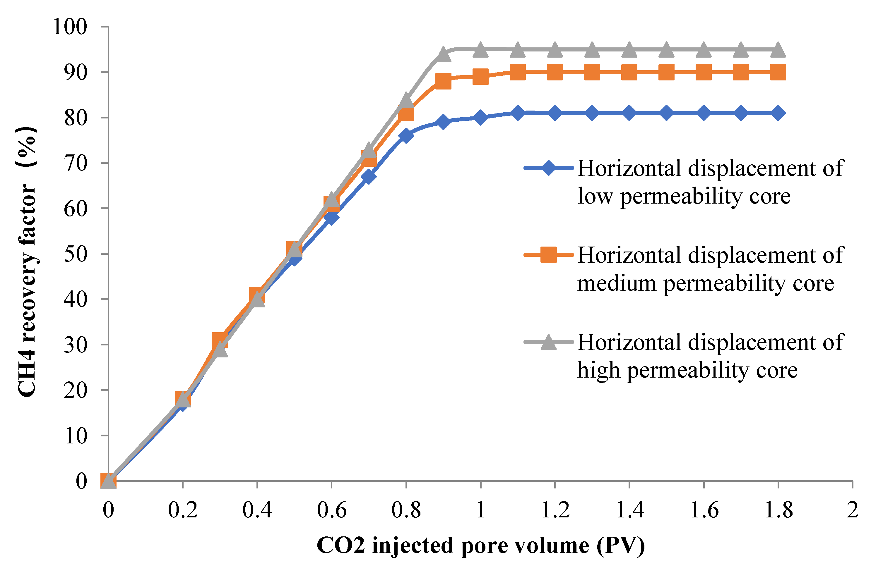
Figure 7 shows the relationship between CH4 recovery factor and CO2 injection pore volume of cores with different permeability under the same injection conditions. It can be seen from Figure 7 that before CO2 breakthrough, the CH4 recovery rate is linearly related to the injected pore volume, with an inclination of 45 °; after CO2 breakthrough, with the increase of core permeability, the recovery factor of CH4 is higher. The research results show that in the low permeability core, the diffusion of CO2 is stronger, the transition zone between CO2 and CH4 is larger, and the produced CH4 is polluted, thus reducing the recovery factor.
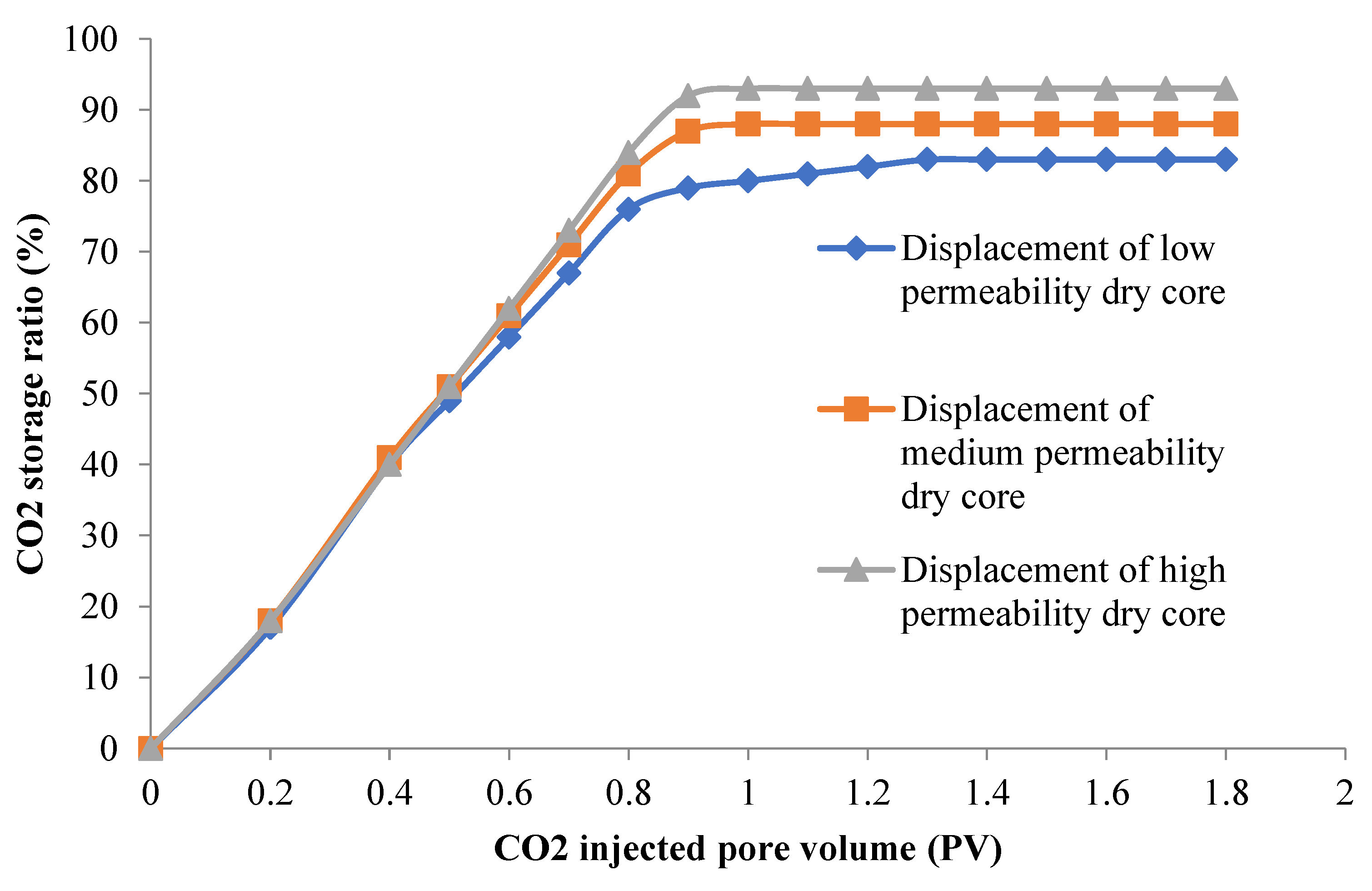
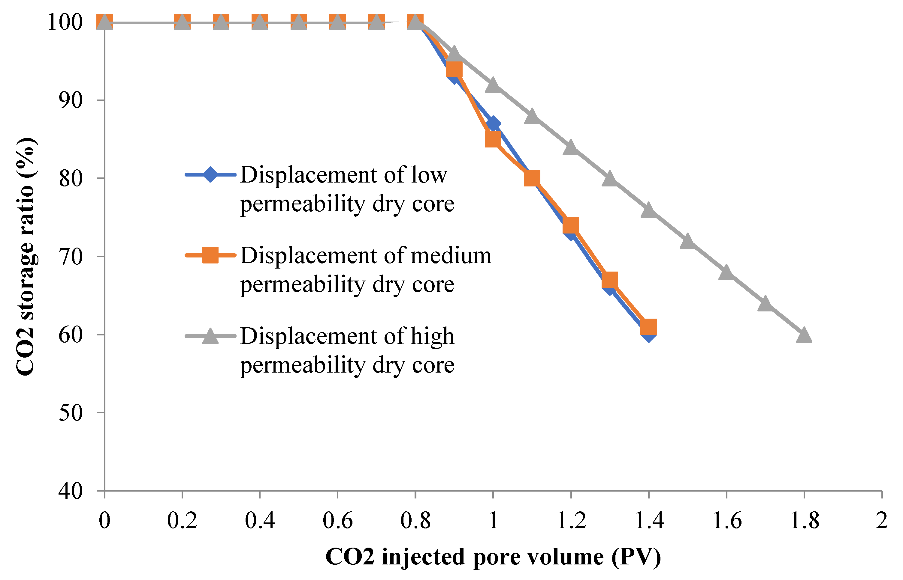
Figure 8 shows the relationship between CO2 storage rate and injected pore volume in cores with different permeability. It can be seen from Figure 8 that before CO2 breakthrough, the CO2 storage rate increases in a 45 ° oblique straight line; after CO2 breakthrough, the CO2 storage rate increases slowly. With the increase of core permeability, the CO2 storage rate increases. Figure 9 shows the relationship between CO2 storage ratio of cores with different permeability and injected pore volume. It can be seen from Figure 9 that with the increase of permeability, the CO2 storage effect of the core is better. The results show that the diffusion of CO2 is stronger in low permeability cores, and the process of displacement of CH4 by CO2 tends to piston displacement with higher permeability.
According to the relationship between the recovery of CH4 in dry and wet cores and the injected pore volume, when bound water exists, there is little CO2 effectively displaced in the initial stage of wet core injection. When the bound water dissolves CO2 to saturation, CH4 is effectively displaced, so the recovery of CH4 lags behind; at the same time, the existence of bound water makes the micro pores in the core mainly filled with water, and CH4 is more likely to be displaced by CO2, making the CH4 recovery of the final wet core slightly higher than that of the dry core.
According to the relationship between the CO2 storage rate and storage ratio of dry and wet cores and the pore volume of CO2 injection, when bound water is not considered in the core, when 1.4PV~1.6PV of CO2 is injected, the retention ratio is about 60%; in the presence of bound water, the CO2 retention rate increases significantly at the same injection of PV, which fully shows that the existence of formation water is conducive to the storage of CO2 in the ground; at the same time, after storage, the underground saturation of CO2 is consistent with the degree of CH4 production, indicating that CO2 occupies In addition to occupying the space of the displaced CH4, a small part of CO2 is also dissolved in the formation water when the bound water exists. The dissolved CO2 accounted for about 1.89% of the pore volume under the conditions of 8Mpa and 80℃, and the higher the pressure, the larger the dissolved amount.

4. Conclusion

With the popularization of natural gas and the requirements of environmental protection, the development and utilization of natural gas is particularly important. The Upper Paleozoic tight sandstone in the Ordos Basin has the characteristics of low porosity, low permeability and concealed gas reservoir. By injecting CO2 into the formation, the recovery rate of natural gas can be effectively improved and the stable storage of CO2 can be realized. This paper takes the complex and tight sandstone of the Upper Paleozoic in the Ordos Basin as the research object. Through laboratory experiments, the effects of displacement rate, fracture dip angle, core permeability, and core dry and wet on CO2 displacement efficiency and storage efficiency are analyzed. The influence of these factors on CO2 displacement and storage efficiency, thereby improving CH4 recovery and CO2 storage efficiency. The main research results are:
(1) For different cores, when the CO2 injection pore volume is lower than 1PV, the relationship between CH4 recovery factor and CO2 injection pore volume is linear, and the inclination angle is 45 °. When the CO2 injection pore volume exceeds 1PV, the CH4 recovery factor increases slightly with the increase of displacement speed; Before CO2 breakthrough, the CO2 storage efficiency increases in a 45 ° oblique straight line. After CO2 breakthrough, the CO2 storage rate increases slowly. After CO2 breakthrough, the CO2 storage rate decreases, and the final CO2 storage rate is consistent. With the continuous injection of CO2, the stored proportion of CO2 in the initial stage is 100%, but when CO2 breaks through, the stored proportion will gradually decrease. When CO2 injection exceeds 1PV, the stored proportion of CO2 under the same PV number is basically the same.
(2) The recovery rate of CH4 displaced by CO2 is generally 87%-97%, and the CO2 breakthrough time is 0.7PV - 0.9PV. After 2.4PV, the CO2 storage rate is basically about 50%; when 1.5-2.4PV is injected, the CO2 storage rate is basically about 50%, and the CO2 saturation in the reservoir is about 55% when there is bound water. The water part accounts for 1.9% PV ; when the displacement rate is lower, the breakthrough time of CO2 is earlier; with the increase of the displacement rate, the final recovery rate of CH4 increases slightly; when the permeability is lower, under the same injection of PV, the CO2 breakthrough time is earlier, and the final CH4 recovery rate is lower; when the bound water exists, the displacement phase CO2 is partially dissolved into the formation water, the CO2 breakthrough lag is about 0.1PV, and the final CH4 recovery rate and CO2 storage rate are higher than that of dry core displacement.
Funding statement: This work was not supported by any funds.
Data availability: The figures and tables used to support the findings of this study are included in the article.

Conflicts of interest:

The authors declare that they have no conflicts of interest.

Acknowledgments

The authors would like to show sincere thanks to those techniques who have contributed to this research.

References

  1. Wu, S.; Zou, C.; Ma, D.; Zhai, X.; Yu, H.; Yu, Z. Reservoir property changes during CO2–brine flow-through experiments in tight sandstone: Implications for CO2 enhanced oil recovery in the Triassic Chang 7 Member tight sandstone, Ordos Basin, China. J. Asian Earth Sci. 2019, 179, 200–210. [Google Scholar] [CrossRef]
  2. Jin, L.; Hawthorne, S.; Sorensen, J.; Pekot, L.; Kurz, B.; Smith, S.; Heebink, L.; Herdegen, V.; Bosshart, N.; Torres, J.; et al. Advancing CO2 enhanced oil recovery and storage in unconventional oil play—Experimental studies on Bakken shales. Appl. Energy 2017, 208, 171–183. [Google Scholar] [CrossRef]
  3. Zhou, X.; Wang, Y.; Zhang, L.; Zhang, K.; Jiang, Q.; Pu, H.; Wang, L.; Yuan, Q. Evaluation of enhanced oil recovery potential using gas/water flooding in a tight oil reservoir. Fuel 2020, 272, 117706. [Google Scholar] [CrossRef]
  4. Li, D. , Saraji, S., Jiao, Z., and Zhang, Y. (2021). CO2 injection strategies for enhanced oil recovery and geological storage in a tight reservoir: An experimental study. Fuel, 284, 119013.
  5. Burrows, L.C.; Haeri, F.; Cvetic, P.; Sanguinito, S.; Shi, F.; Tapriyal, D.; Goodman, A.L.; Enick, R.M. A Literature Review of CO2, Natural Gas, and Water-Based Fluids for Enhanced Oil Recovery in Unconventional Reservoirs. Energy Fuels 2020, 34, 5331–5380. [Google Scholar] [CrossRef]
  6. Wang, L.; Tian, Y.; Yu, X.; Wang, C.; Yao, B.; Wang, S.; Winterfeld, P.H.; Wang, X.; Yang, Z.; Wang, Y.; et al. Advances in improved/enhanced oil recovery technologies for tight and shale reservoirs. Fuel 2017, 210, 425–445. [Google Scholar] [CrossRef]
  7. Zhu, C.-F.; Guo, W.; Wang, Y.-P.; Li, Y.-J.; Gong, H.-J.; Xu, L.; Dong, M.-Z. Experimental study of enhanced oil recovery by CO2 huff-n-puff in shales and tight sandstones with fractures. Pet. Sci. 2020, 18, 852–869. [Google Scholar] [CrossRef]
  8. AlRassas, A.M. , Vo Thanh, H., Ren, S., Sun, R., Al-Areeq, N.M., Kolawole, O., and Hakimi, M.H. (2022). CO2 Storage and Enhanced Oil Recovery via the Water Alternating Gas Scheme in a Mixed Transgressive Sandstone-Carbonate Reservoir: Case Study of a Large Middle East Oilfield. Energy and Fuels, 36(17), 10299-10314.
  9. Chaturvedi, K.R.; Sharma, T. In-situ formulation of pickering CO2 foam for enhanced oil recovery and improved carbon storage in sandstone formation. Chem. Eng. Sci. 2021, 235, 116484. [Google Scholar] [CrossRef]
  10. Wang, Y.; Shang, Q.; Zhou, L.; Jiao, Z. Utilizing macroscopic areal permeability heterogeneity to enhance the effect of CO2 flooding in tight sandstone reservoirs in the Ordos Basin. J. Pet. Sci. Eng. 2020, 196, 107633. [Google Scholar] [CrossRef]
  11. He, Y.; Qiao, Y.; Qin, J.; Tang, Y.; Wang, Y.; Chai, Z. A Novel Method to Enhance Oil Recovery by Inter-Fracture Injection and Production Through the Same Multi-Fractured Horizontal Well. J. Energy Resour. Technol. 2021, 144. [Google Scholar] [CrossRef]
  12. Zhang, K.; Li, S.; Liu, L. Optimized foam-assisted CO2 enhanced oil recovery technology in tight oil reservoirs. Fuel 2020, 267, 117099. [Google Scholar] [CrossRef]
  13. Sun, L. , Bai, B., Wei, B., Pu, W., Wei, P., Li, D., and Zhang, C. (2019). Recent advances of surfactant-stabilized N2/ CO2 foams in enhanced oil recovery. Fuel, 241, 83-93.
  14. Bai, M.; Zhang, Z.; Chen, Q.; Weifeng, S.; Du, S. Research on the Enhanced Oil Recovery Technique of Horizontal Well Volume Fracturing and CO2 Huff-n-Puff in Tight Oil Reservoirs. ACS Omega 2021, 6, 28485–28495. [Google Scholar] [CrossRef] [PubMed]
  15. Zuo, M.; Chen, H.; Qi, X.; Liu, X.; Xu, C.; Yu, H.; Brahim, M.S.; Wu, Y.; Liu, H. Effects of CO2 injection volume and formation of in-situ new phase on oil phase behavior during CO2 injection for enhanced oil recovery (EOR) in tight oil reservoirs. Chem. Eng. J. 2023, 452, 139454. [Google Scholar] [CrossRef]
  16. Cheng, H.; Ma, P.; Dong, G.; Zhang, S.; Wei, J.; Qin, Q. Characteristics of Carboniferous Volcanic Reservoirs in Beisantai Oilfield, Junggar Basin. Math. Probl. Eng. 2022, 2022, 1–10. [Google Scholar] [CrossRef]
  17. Rajkumar, P.; Pranesh, V.; Kesavakumar, R. Influence of CO2 retention mechanism storage in Alberta tight oil and gas reservoirs at Western Canadian Sedimentary Basin, Canada: hysteresis modeling and appraisal. J. Pet. Explor. Prod. Technol. 2021, 11, 327–345. [Google Scholar] [CrossRef]
  18. Baban, A.; Keshavarz, A.; Amin, R.; Iglauer, S. Residual Trapping of CO2 and Enhanced Oil Recovery in Oil-Wet Sandstone Core – A Three-Phase Pore-Scale Analysis Using NMR. Fuel 2023, 332. [Google Scholar] [CrossRef]
  19. Lake, L.W. , Lotfollahi, M., and Bryant, S.L. (2019). CO2 enhanced oil recovery experience and its messages for CO2 storage. In Science of Carbon Storage in Deep Saline Formations (pp. 15-31). Elsevier.
  20. Han, J., Cheng, H., Shi, Y., Wang, L., Song, Y., Zhnag, W. (2016) Connectivity analysis and application of fracture cave carbonate reservoir in Tazhong. Science Technology and Engineering 2016, 16, 147–152.
  21. Milad, M.; Junin, R.; Sidek, A.; Imqam, A.; Tarhuni, M. Huff-n-Puff Technology for Enhanced Oil Recovery in Shale/Tight Oil Reservoirs: Progress, Gaps, and Perspectives. Energy Fuels 2021, 35, 17279–17333. [Google Scholar] [CrossRef]
  22. Huang, X.; Li, A.; Li, X.; Liu, Y. Influence of Typical Core Minerals on Tight Oil Recovery during CO2 Flooding Using the Nuclear Magnetic Resonance Technique. Energy Fuels 2019, 33, 7147–7154. [Google Scholar] [CrossRef]
  23. Hou, Z.-K.; Cheng, H.-L.; Sun, S.-W.; Chen, J.; Qi, D.-Q.; Liu, Z.-B. Crack propagation and hydraulic fracturing in different lithologies. Appl. Geophys. 2019, 16, 243–251. [Google Scholar] [CrossRef]
  24. Bai, J.; Liu, H.; Wang, J.; Qian, G.; Peng, Y.; Gao, Y.; Yan, L.; Chen, F. CO2, Water and N2 Injection for Enhanced Oil Recovery with Spatial Arrangement of Fractures in Tight-Oil Reservoirs Using Huff-‘n-puff. Energies 2019, 12, 823. [Google Scholar] [CrossRef]
  25. Alvarado, V.; Manrique, E. Enhanced Oil Recovery: An Update Review. Energies 2010, 3, 1529–1575. [Google Scholar] [CrossRef]
  26. Cheng, H.; Wei, J.; Cheng, Z. Study on Sedimentary Facies and Reservoir Characteristics of Paleogene Sandstone in Yingmaili Block, Tarim Basin. Geofluids 2022, 2022, 1–14. [Google Scholar] [CrossRef]
  27. Mahzari, P.; Jones, A.P.; Oelkers, E.H. Impact of in-situ gas liberation for enhanced oil recovery and CO2 storage in liquid-rich shale reservoirs. Energy Sources, Part A: Recover. Util. Environ. Eff. [CrossRef]
  28. Kashkooli, S.B. , Gandomkar, A., Riazi, M., and Tavallali, M. S. (2022). Coupled optimization of carbon dioxide storage and CO2 enhanced oil recovery. Journal of Petroleum Science and Engineering 2022, 208, 109257. [Google Scholar]
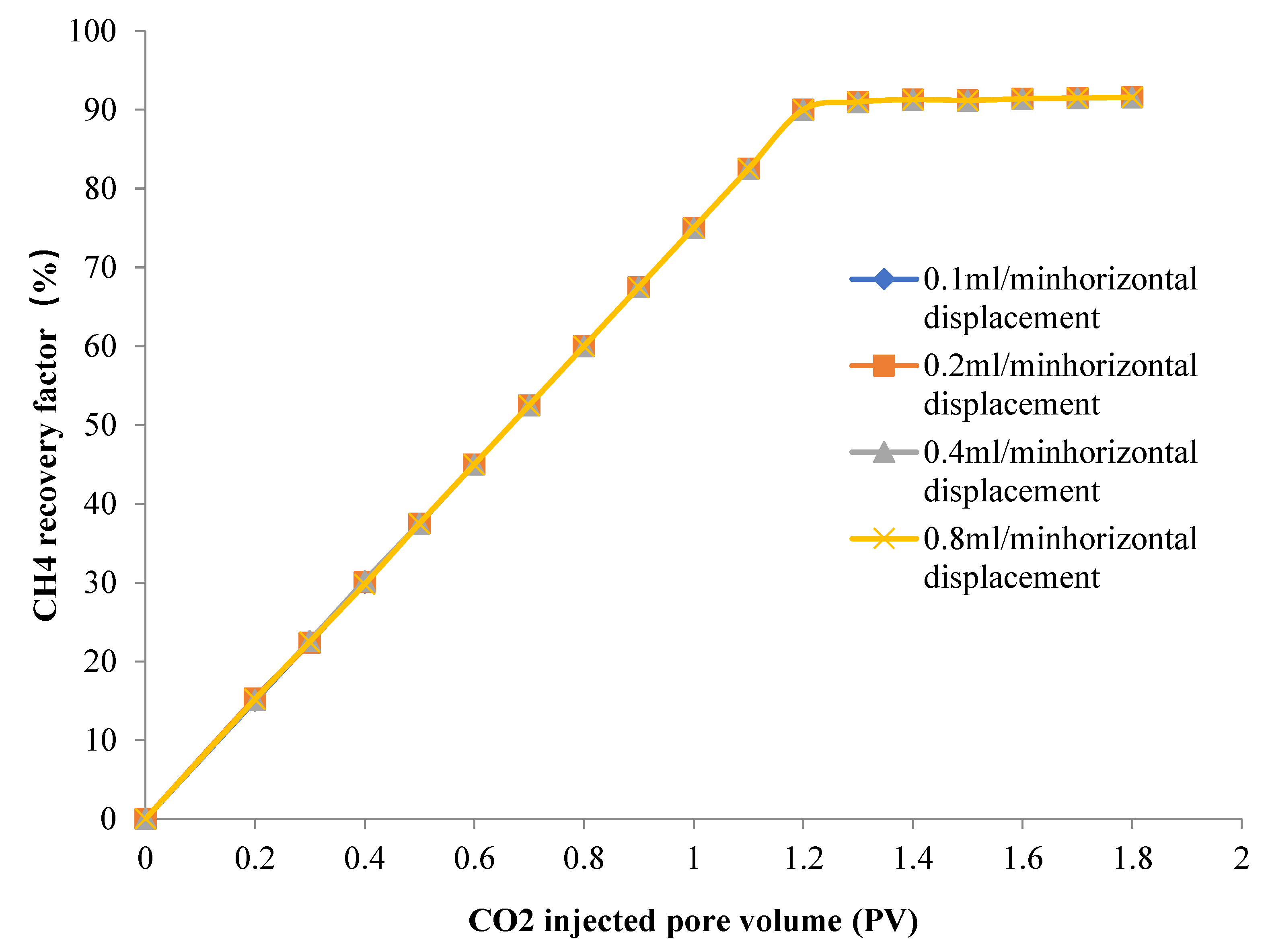
Figure 1. CH4 recovery of cores with different displacement velocities varies with the pore volume of CO2 injection.
Preprints 75254 g001
Figure 2. CO2 storage efficiency in cores under different displacement rates.
Preprints 75254 g002
Figure 3. CO2 storage ratio in cores under different displacement rates.
Preprints 75254 g003
Figure 4. CH4 recovery of cores with different displacement velocities varies with the pore volume of CO2 injection.
Preprints 75254 g004
Figure 5. CO2 storage efficiency in cores under different displacement angles.
Preprints 75254 g005
Figure 6. CO2 storage ratio in cores under different displacement angles.
Preprints 75254 g006
Figure 7. CH4 recovery factor with CO2 injection pore volume in cores with different permeability.
Preprints 75254 g007
Figure 8. CO2 storage efficiency in cores with different permeability.
Preprints 75254 g008
Figure 9. CO2 storage ratio in cores with different permeability.
Preprints 75254 g009
Table 1. Characteristics of each stratum in the study area.
Stratum name Stratigraphic characteristics
Lower Shihezi Formation It is widely distributed on the plane and basically distributed in the whole study area. It is composed of He1 Member, He2 Member and He3 Member longitudinally. The lithology is mainly sandstone, with a certain amount of mudstone mixed between them. The reservoir physical property of Xiahezi Formation sandstone is the best, and it is the most important reservoir in this area.
Upper Shihezi Formation It is widely distributed on the plane. The lithology is sandstone and mudstone. The thickness of mudstone is relatively large, with a total thickness of more than 100 meters. It has good capping capacity, providing good capping conditions for natural gas accumulation.
Shiqianfeng Formation The whole area is distributed on the plane, and the lithology is dominated by sandstone and mudstone. As a regional caprock, mudstone is thicker and has stronger sealing capacity.
Table 2. Experimental scheme of different cores.
Experiment order Influencing factors Experimental content
1 Displacement$Speed 0.1ml /min horizontal displacement of medium-seepage dry core
2 0.2ml /min horizontal displacement of dry cores with medium permeability
3 0.4ml /min horizontal displacement of dry cores with medium permeability
4 0.8ml /min horizontal displacement of medium-seepage dry core
5 Inclination 0.2ml /min, inlet +45°displacement medium seepage dry core
6 0.2ml /min, inlet -10°displacement medium seepage dry core
7 0.2ml /min, inlet -45°displacement medium seepage dry core
8 Penetration 0.2ml /min horizontal displacement of low seepage dry core
9 0.2ml /min horizontal displacement of high seepage dry core
10 Bound water 0.2ml /min displacement of medium seepage cores with bound water
Table 3. Composition of formation water samples in the experiment.
K++Na+ Mg2+ Ca2+ Cl SO32– HCO3 CO32– Total salinity (mg/l)
12170 26 31 17380 270 2431 0 32308
Table 4. Low permeability core physical parameter information table.
Core number Core length (cm) Core diameter (cm) Pore volume (cm3) Porosity (%) Permeability (10-3μm2)
1 4.31 2.51 2.35 11.2 1.8
2 4.84 2.56 2.73 11.0 1.8
3 5.11 2.49 2.85 11.3 2.3
4 5.23 2.51 2.91 11.4 2.4
5 5.32 2.49 2.83 11.0 2.3
6 4.53 2.53 2.51 11.4 1.9
7 4.64 2.48 2.83 11.2 1.9
8 5.01 2.56 2.75 11.4 2.6
9 5.32 2.56 2.82 11.1 2.1
10 5.21 2.53 2.84 11.3 2.0
Disclaimer/Publisher’s Note: The statements, opinions and data contained in all publications are solely those of the individual author(s) and contributor(s) and not of MDPI and/or the editor(s). MDPI and/or the editor(s) disclaim responsibility for any injury to people or property resulting from any ideas, methods, instructions or products referred to in the content.
Copyright: This open access article is published under a Creative Commons CC BY 4.0 license, which permit the free download, distribution, and reuse, provided that the author and preprint are cited in any reuse.
Prerpints.org logo

Preprints.org is a free preprint server supported by MDPI in Basel, Switzerland.

Subscribe

© 2024 MDPI (Basel, Switzerland) unless otherwise stated