1. Introduction
Steel sheets of various grades and thickness are widely employed in the automotive industry to produce lightweight car bodies. Joining various body parts is essential, and commonly used methods for steel parts include resistance spot welding, laser welding, brazing, soldering etc. [
1,
2]. The oldest and most widespread method of joining steel sheets in the automotive industry is resistance spot welding. Resistance spot welding (RSW) is a joining technique that eliminates the need for additional material during the process. It involves applying high-intensity current and pressure with welding electrodes. The process utilizes the heat generated by the current to achieve the necessary welding temperature for joining two or more materials. However, in welding processes, the thermal after-effects and distortion are obtained [
3,
4,
5]. RSW as the predominant technique for metal joining is commonly employed for similar metal materials. However, when dissimilar metals are welded together, there is a risk of welding defects due to substantial variations in their physical and chemical properties. This can compromise the overall quality of the joints [
6,
7]. The process of RSW depends on the type of used materials and specific welding parameters. The parameters typical for RSW are the welding current, welding time, and electrode pressing force. It is important to note that, welding parameters significantly affect the quality of the joint [
8,
9]. Ma et al. [
10] conducted research on resistance spot welding of high-strength (HSS) steel sheets. They investigated the formation process of the nugget under different welding conditions using experimental measurement and FEM simulation. The FEM simulation accurately predicted the nugget sizes and formation process. The effect of welding parameters on the quality of spot welds of combination of various high-strength steels investigated Kaščák et al. [
11]. Increasing welding current values led to higher carrying capacities in a linear dependence. H. Oikawa et al. [
12] described in the paper that suitable welding current range of HSS sheets during resistance spot welding shifted to the lower current side compared with that of mild steel sheets and it was affected by the electrode force. Midawi et al. [
13] studied the impact of the microstructures and mechanical properties of resistance spot welds in advanced high-strength steels (AHSS) on the overall failure response of structural assemblies in crash events. The strain localization occurs in regions with lower hardness, such as the subcritical heat-affected zone (HAZ), while limited deformation is observed in harder regions like the upper-critical HAZ and fusion zone. Eftekharimilani et al. [
17] presented study on the effects of single and double pulse resistance spot welding on the microstructures of an advanced high strength steel (AHSS). The focus is on how the double pulse welding schemes affect the primary weld nugget, particularly by partially remelting it and annealing the fusion boundary area. The double pulse welds demonstrate a favourable failure mode. Chung et al. [
9] analysed failure analysis of resistance spot welded AHSS. The authors concluded that in the examined welds, there was a significant decrease in ductility at the weld nugget such that it resulted in interfacial failure. X. Wan et al. [
19] showed in their article that the welding parameter- welding current influences the mechanical properties of resistance spot welded dual-phase steel welds. H. Moshayedi and I. Sattari-Far [
20] declared as part of their research, that welding parameter - welding current has a significant impact on nugget formation compared to welding time using finite element analysis. M. Eshraghi et al. [
21] in their article concluded that welding current is the most influential and important factor in weld properties using the SYSWELD simulation software. B. Varbai et al. [
22] investigated the shear tension strength of resistance spot welded ultra-high-strength steels. The authors concluded that the softening in the sub-critical heat-affected zone was found to be greater with the longer welding time.
Due to factors such as high thermal conductivity, the presence of a natural surface oxide layer, zinc layer and other challenges, connecting lightweight materials through welding techniques poses difficulties. Furthermore, the emission of sparks and smoke during the welding process raises environmental concerns. Hence, other methods for assembly process can be utilized in joining high-strength steel sheets such as adhesive bonding, fastening, riveting, clinching, clinch-riveting or self-piercing riveting [
23,
24].
Over the past three decades, clinching has emerged as a fast-growing mechanical joining method in the automotive and aerospace sectors. Clinching joining technology has emerged as a promising solution for lightweight constructions that require high production rates, especially when joining hybrid metal-composite parts [
25,
26]. Clinching is a fast and localized mechanical fastening technique that involves deforming two or more sheet components through plastic deformation. The process utilizes a punch, a blank holder, and a specialized die assembly. By pressing the forming sheets, which are initially clamped between the blank holder and the die assembly, a friction-based interlocking connection is created between the sheet components [
27,
28,
29,
30]. The clinching process of materials with various thicknesses and mechanical property arrangements was investigated by Mucha et al. [
31]. The sheet thickness arrangement in relation to the die is an important parameter influencing the load-bearing capacity. Abe et al. [
32] studied the mechanical clinching, using modified dies, and resistance spot welding that was used to join ultra-high strength steel sheets with low ductility. The static joint loads for resistance spot welding were larger than those of clinching in tension–shearing and cross-tension test.
In the automotive industry, the clinched joint is taken as an alternative to spot resistance welding. The main disadvantage of clinched joints is their lower load-bearing capacity compared to spot resistance welds [
32,
33,
34]. This results in efforts to increase the load-bearing capacity of clinched joints. Efforts to increase the load-bearing capacity of clinching joints led to research in the field of heat treatment of clinched joints, or to a combination with adhesive bonding.
Lei et al. [
35] studied the application and evaluation of clinch-bonded hybrid joining technology in various manufacturing disciplines. The study focuses on specimens made of similar and dissimilar sheets of H62 copper alloy, aluminium alloy, and galvanized steel. The shear strength of the specimens, primarily influenced by the adhesive, outperforms their peeling strength, which is closely associated with the clinched structures. Ma et al. [
36] investigated the dynamic flow behaviour of adhesive during the clinch-bonding process and its impact on joint formation. The lower clamping force should be employed in the clinch-bonding to ensure sufficient handling strength of the joint before the adhesive is cured. Balawender [
37] deals with two different manufacturing procedures: adhesive curing before clinching and clinching before adhesive curing. They found clinching before adhesive curing is a more effective technology for achieving stronger joints.
Sia et al. [
38] studied behaviour and durability of clinch joints at room temperature, 100 °C, and 250 °C. The ultimate tensile shear strength remains relatively unchanged with temperature increase, but stiffness and energy absorption decrease at higher temperatures. Zeuner et al. [
39] investigated the effect of heat treatment on the forming process and mechanical properties of clinch joints made from a highly formable sheet material. The study examines the impact of heat treatment, which involves the formation of an oxidation layer on the sheet surface, on the forming process and resulting mechanical properties of clinch joints. The findings demonstrate clear influences of heat treatment-induced surface roughness on joint geometry and strength. Kaczyński et al. [
40] studied a new method to enhance the strength of clinch joints involves heating the sheet from the side of the die prior to the joining process. The results demonstrate that increasing the temperature of the bottom component before deformation leads to an increase in shear strength as well as in cross tensile strength. Zhang et al. [
41] evaluated a novel method of joining for aluminium alloy 5052. The method combines principles of mechanical clinching and resistance spot welding. however, the resulting joint shape was not a clinched joint with its characteristic shape. The results demonstrate that the resistance spot clinched joints exhibit superior load-bearing capacity compared to traditional resistance spot welding joints. Wang et al. [
42] introduced a novel method called incremental laser shock clinching, which is used to create a round end rectangular joint with a total length much larger than the diameter of the laser spot. The research verified the feasibility of this method to join copper, aluminum, and stainless steel. Development of hot stamping clinching tool was investigated by Chen [
43]. The stamping clinching tool incorporates a forming system, a heating system, and a cooling system. They found the high cooling rate employed in the experiments increases the tensile strength of the sheet at the clinching point by 3 to 4 times.
In order to increase the load-bearing capacity of the clinched joints of the joined materials HCT600X+Z and HX420LAD+Z, the microstructure was locally modified in the areas of the clinched joint. The change of the microstructure in the clinched joint was achieved by local heating using the resistance spot welding method. The distribution of the thus modified microstructure in the clinched joint was analysed by light and electron microscopy techniques, and by measuring microhardness. The load-bearing capacity of clinched joints treated by local heating in this way was compared with the load-bearing capacity of joints without heat treatment. Numerical simulation software was used to predict the material flow of the heat-affected (preheated) microstructure of the joined materials during clinching process.
2. Materials and Methods
2.1. Experimental Materials
The selection of experimental material was targeted at two-phase hot-dip galvanized steels of 1.5 mm thickness and fine-grained microalloyed low-carbon hot-dip galvanized steels of 1.5 mm thickness. The material of the first experimental group belongs to the progressive high-strength steels. Its designation according to EN 10346/09 was HCT 600 X+Z. The HCT 600 X+Z steel sheet had a surface galvanised on both sides, the thickness of the sheet was 1.5 mm. In the second experimental group, the steel sheet HX420LAD+Z was galvanized on both sides, and its thickness was 1.5 mm. The chemical composition of the steels was determined by optical emission spectroscopy (OES, Thermo ARL, Switzerland, Lausanne). The chemical elemental composition of the experimental materials was focused on the determination of the concentration of the main alloying elements (
Table 1 and
Table 2).
The mechanical properties of the experimental materials were determined by tensile testing at an ambient temperature according to ISO 6892-1:2019 on flat samples of 1.5 mm thickness with a measured length of L
0 =80 mm and a cross-member movement rate of 0.05 mm/min. For the ambient temperature tensile tests, a TiraTest 2300 universal testing machine (TIRA GmbH, Schalkau, Germany) with a force transducer up to 100 kN was used. Basic mechanical properties of joined materials are shown in
Table 3.
2.2. Numerical Simulation
Mechanical clinching is an inexpensive joining process that involves cold joining two sheets through localized hemming using a punch and die. In the traditional mechanical clinching method, the punch and die are utilized to shape the sheets and create an interlock between the lower and upper sheets. During the clinching forming process, the punch applies pressure to the upper sheet, causing it to flow onto the lower sheet. The lower sheet is supported by a rigid die. As a result, both sheets undergo plastic deformation, leading to the creation of a mechanically interlocked structure known as the clinched point [
44,
45].
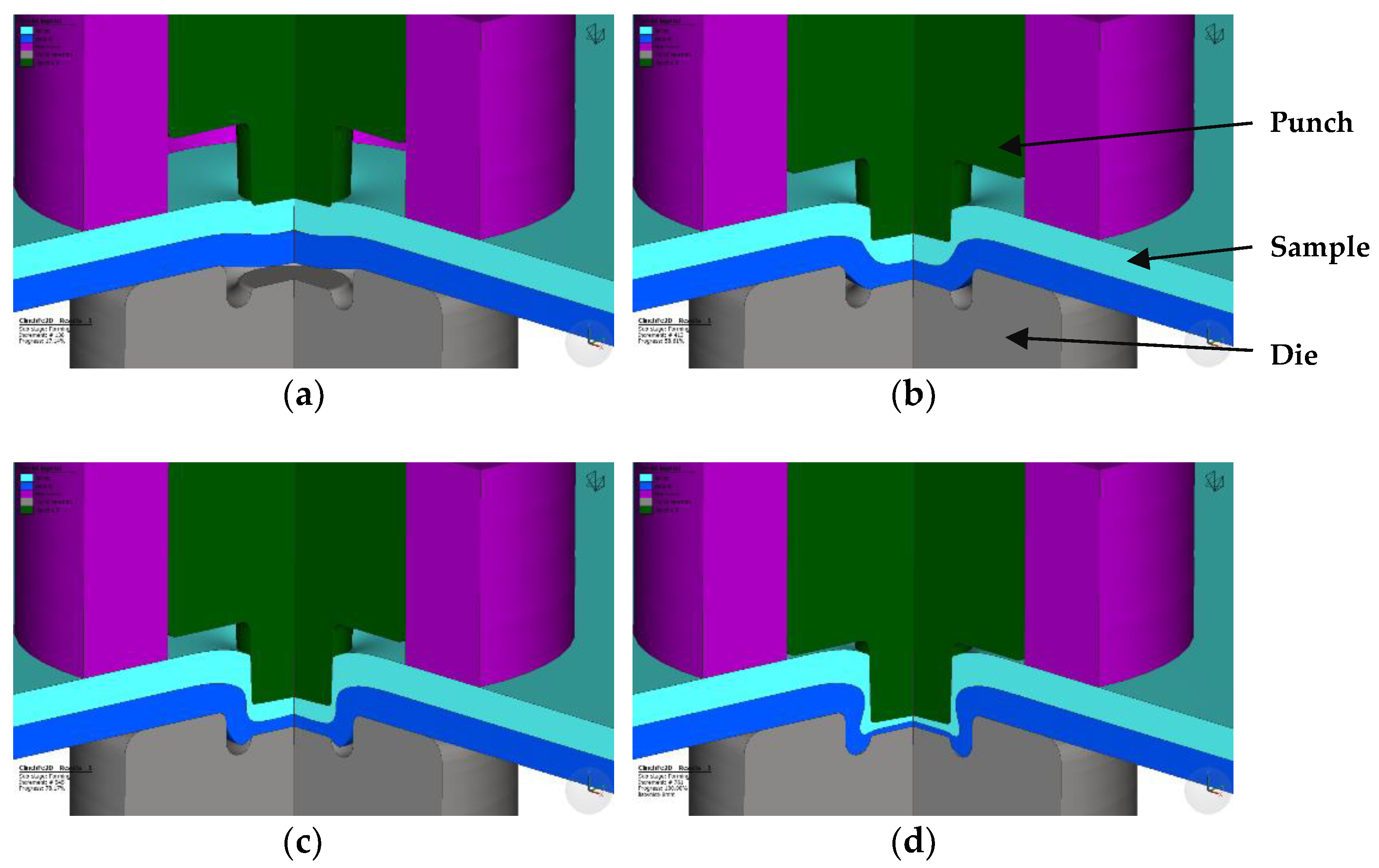
Typical steps of creating the clinched joint include clamping, pressing, bottom forming and interlock forming (
Figure 1). The pre-forming of the parts has a significant impact on the outcome of the joining process. Particularly, the pre-forming of the material on the punch side has a greater influence on the joining parameters compared to the material on the die side.
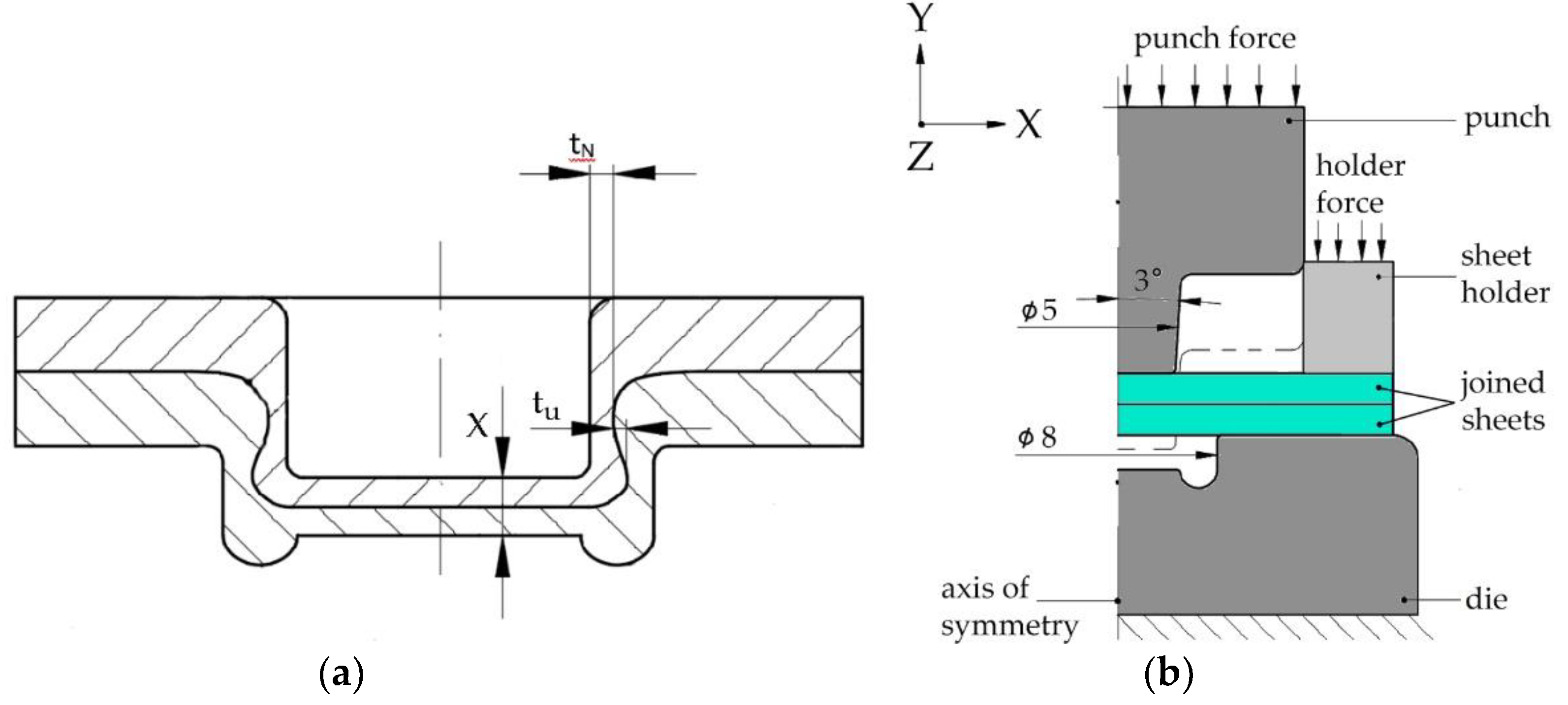
Figure 2a shows the thickness of the neck (
tN), joint bottom thickness (
X) and interlock (
tu) are the main parameters that significantly affect the load-bearing capacity of the clinched joint [
30,
31,
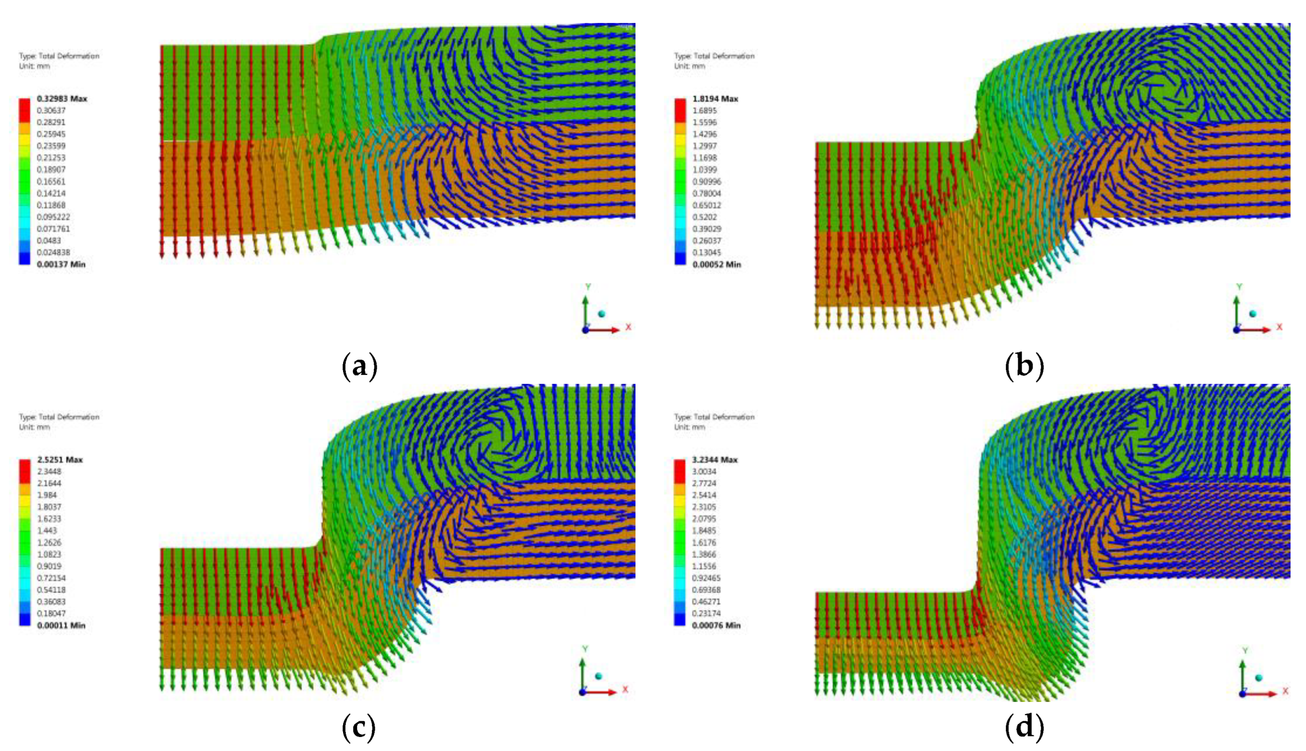
32]. The goal of the numerical simulation was to identify the zones in the sheet metal that are moved to the area of the neck of the clinched joint.
The Ansys Workbench software was used for numerical simulation of clinching process. To simplify the task, a 2D model was employed due to the axial symmetry of the tools and the joint. Consequently, the anisotropy of the joined materials was not taken into account in the calculation.
Figure 2b illustrates a schematic representation of the simulation model’s input geometry, including the basic dimensions and the limiting conditions of the simulation. The nodal points of the die were removed to prevent movement during the simulation, while the nodal points of the punch elements were allowed to move only in the Y axis. Another boundary condition involved applying a force of 400 N on the sheet holder to secure the joined materials during the simulation of the CL joining. Once the desired path was achieved, the punch moved backward to its starting position, simultaneously releasing the force from the sheet holder. In this simulation, the punch, die, and sheet holder were considered perfectly rigid and non-deformable bodies, whereas the joined sheets were modeled as deformable bodies. A multilinear material model was employed to describe the response of the joined material to the applied load. The material model input values for the joined materials can be found in
Table 3. The plastic portion of the material model followed the Holomon hardening law, with the strain hardening exponent determined experimentally based on a standardized tensile test.
For the joined materials, a finite element mesh consisting of 2D quadrangular elements (PLANE 182) was used. These elements are recommended for simulating 2D axis-symmetric problems. Each node of these elements had two degrees of freedom, representing displacements in the X and Y axes. The element size in the mesh was set to 0.1 mm.
In processes like clinching, where both the sheet and the finite element mesh undergo significant deformation, it becomes necessary to remesh the elements at certain intervals [
46]. This remeshing process, known as adaptive remeshing, is controlled by the deformation energy criterion.
At predefined intervals, the deformation energy of each element in the finite element mesh is monitored. If the energy exceeds the limits calculated by the program, adaptive remeshing is initiated. Frictional contacts were modeled between the tools and joined materials, as well as between the joined materials themselves, using friction coefficients of 0.12 for tool-sheet contact and 0.2 for sheet-sheet contact.
2.3. Local Preheating
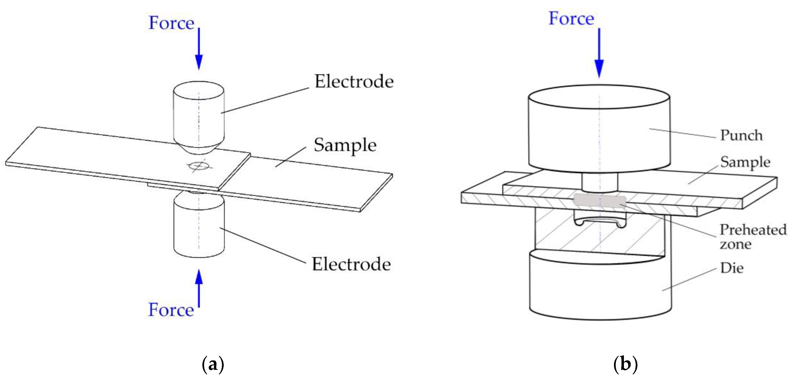
Local intense heating (RSW) was applied to a pair of overlapping hot-dip galvanized sheets, each 1.5 mm thick. The local heating was at the location of the future clinched joint (
Figure 3a). The local heating was performed with a BPK 20 spot pneumatic welder (VTS Elektro s.r.o. Bratislava, Slovakia) with adjustable welding parameters (electrode pressure, welding time, welding current) and with 30 different pre-set welding programs. The heating parameters were selected on the basis of the experience gained in the field of welding and then optimized for the implementation of local heating of the material. For local heating, Cu-Cr welding electrodes according to ON 42 3039.71 were used. The working surfaces of the welding electrodes were Ø 8 mm with a conical finish.
The local heating parameters set on the spot resistance welder were:
welding current I4 = 3.9 kA,
welding time T = 36 periods (1per. = 0.02 s),
pressing force of electrodes Fz = 6 kN.
After the local pre-heating using spot welding electrodes, the samples were subsequently joined at the preheating area by the clinching method (
Figure 3b). A die with a diameter of Ø 5 mm and a die with a diameter of Ø 8 mm were used. The force applied to the die was set to 80 kN.
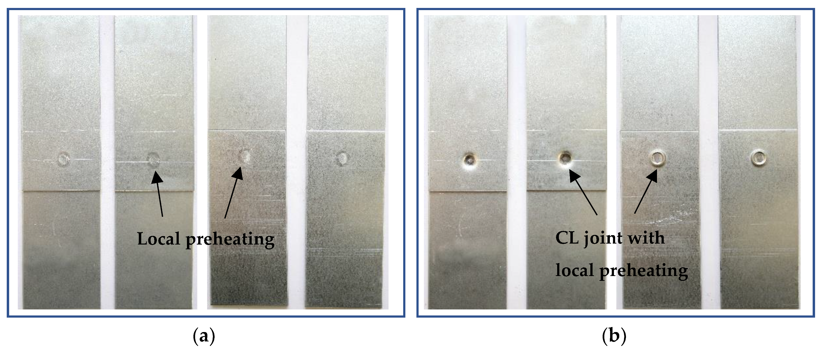
Local pre-heated samples prepared by resistance spot welding and joined by clinching with local preheating are shown in
Figure 4.
2.4. Tensile Test
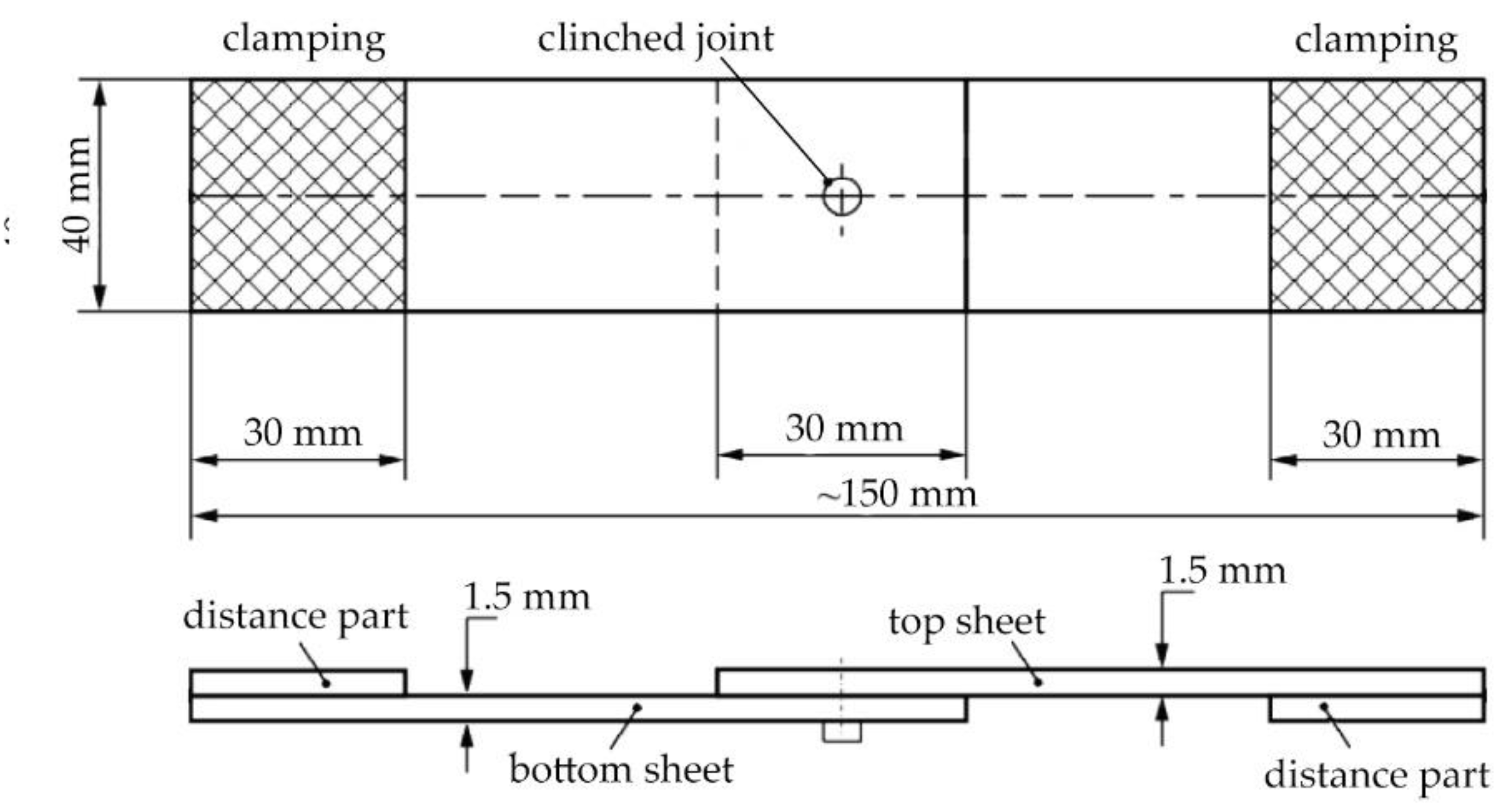
The tensile shear tests were performed for single-lap joint specimens in accordance with the guidelines from ISO 12996: 2013 [
47]. Test samples measuring 40 x 90 mm were used to evaluate the load-carrying capacity of the clinched joints (see
Figure 5). TiraTest 2300 universal testing machine (TIRA GmbH, Schalkau, Germany) was used the tensile test.
After the tensile test, the method of failure of the clinched joint is also evaluated. Typical failure modes of clinched joints according to standard ISO 12996:2013 are: pull-out, neck fracture, neck fracture with plastic deformation (mixed mode failure) and pull-out with neck fracture (mixed failure). All of failure modes of clinched joints are illustrated in
Figure 6.
The two most frequently occurring failure modes of clinched joints are [
48]:
The pull-out mode is distinct from the neck fracture mode as it involves the complete separation of the upper and lower sheets. This mode is characterized by a lack of sufficient geometric interlocking in the mechanical clinched joint. When subjected to tensile-shear loading, the two sheets experience plastic deformation and eventually slide apart when the strength of the interlock becomes weaker than the applied tensile load.
The neck fracture mode is characterized by a fracture occurring in the thinnest part of the upper sheet’s neck. When subjected to tensile-shear loading, a force is applied to the neck of the upper sheet in a shearing motion. As the load increases, the shearing force on the thinnest part of the neck gradually increases. Eventually, when the neck becomes thinner, a ring fracture occurs once the shearing force reaches the strength of the thinnest neck.
2.5. Light and Scanning Electron Microscopy
The experimental materials and the fabricated clinched joints were sampled by electrospark machining for light microscope and scanning electron microscope analyses. Subsequently, the samples were prepared in conductive dentacryl, ground on 240, 400, 600, and 800 grit sandpaper moistened with water, polished with diamond paste, 1/0 grit on satin moistened with kerosene, washed and rinsed with petroleum alcohol. Samples were cleaned in methanol in ultrasonication before observation. The microstructure was developed by etching in Nital (2% nitric acid solution in ethyl alcohol).
An experimental light microscopy technique was used for the analyses: an Olympus CX71 inverted metallographic microscope with an Olympus DP12 camera (OLYMPUS Europa Holding GmbH, Hamburg, Germany). For the Olympus CX71 microscope, the accessories for observation in polarized light and by differential interference contrast were used. For detailed analyses of the microstructures, a scanning electron microscope (SEM) JEOL JSM-7000F (Jeol Ltd., Tokyo, Japan) with an energy-dispersive X-ray (EDX) analyser INCA X-sight model 7557 (Oxford Instruments, Abingdon, Oxfordshire, UK) and an environmental scanning electron microscope EVO MA15 (Carl Zeiss Microscopy GmbH, Jena, Germany) with an EDX analyser X-Max 50 model 51-XMX1003 (Oxford Instruments, Abingdon, Oxfordshire, UK). An accelerating voltage of 20 kV and a sample-to-surface distance of 10 mm was used for analyses in SEI (secondary electron) mode and in BSE (backscattered electron) mode for observations in chemical contrast.
2.6. Microhardness Measurement
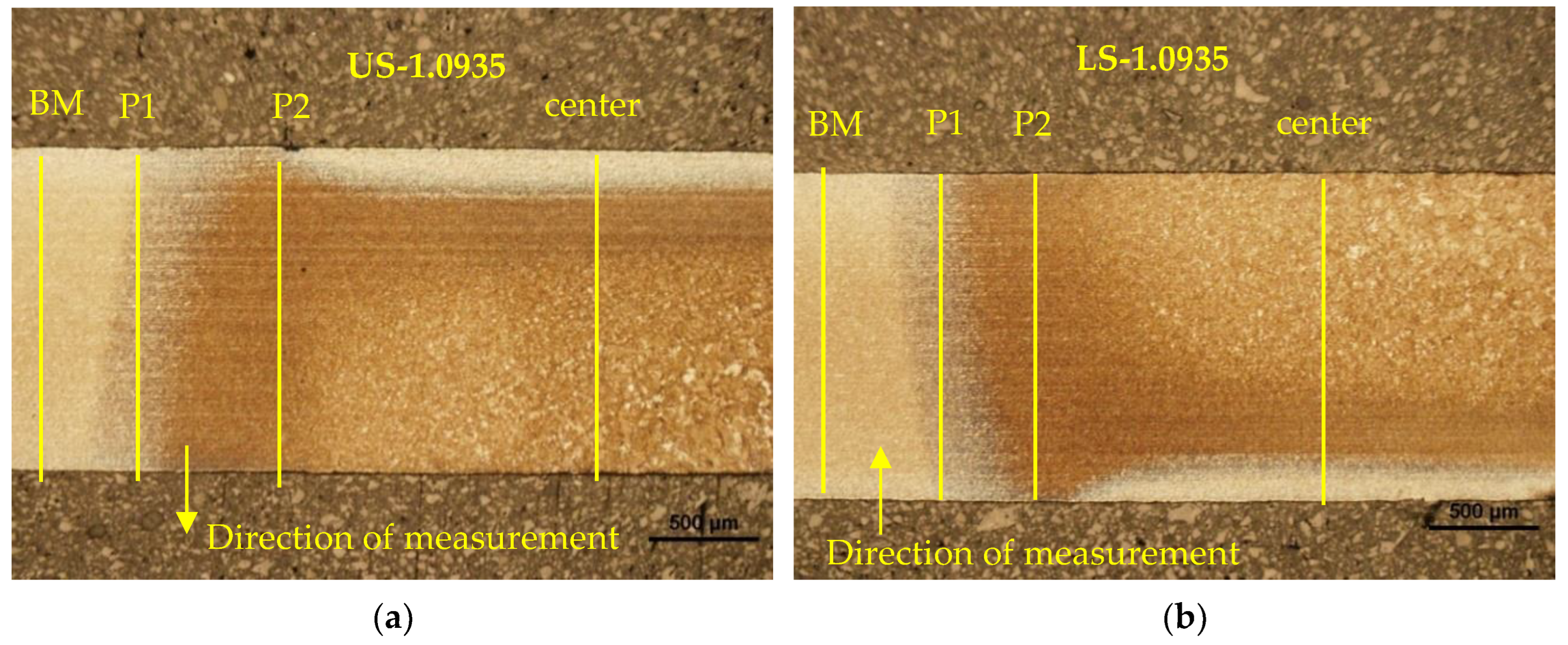
A WILSON-WOLPERT Tukon 1102 microhardness tester (Buehler ITW Co, Lake Bluff, IL, USA) was used to measure the microhardness HV0.3 in the gradient microstructure zones and in the clinching junction. The distance between the measurements was 0.15 mm. Individual hardness measurement zones for the welded joint and the clinched joint with pre-heated are shown in the
Figure 7.
Figure 1.
Steps of the clinching process: (a) clamping, (b) pressing, (c) bottom forming, (d) interlock forming.
Figure 1.
Steps of the clinching process: (a) clamping, (b) pressing, (c) bottom forming, (d) interlock forming.
Figure 2.
Characteristics of clinching: (a) main parameters of clinched joint, (b) geometrical model and boundary conditions of clincing in numerical simulation.
Figure 2.
Characteristics of clinching: (a) main parameters of clinched joint, (b) geometrical model and boundary conditions of clincing in numerical simulation.
Figure 3.
Procedure of making sample for experiments: (a) pre-heating by welding electrodes and (b) clinching pre-heated area.
Figure 3.
Procedure of making sample for experiments: (a) pre-heating by welding electrodes and (b) clinching pre-heated area.
Figure 4.
Samples for experiments: (a) prepared by resistance spot welding, (b) clinched with local preheating.
Figure 4.
Samples for experiments: (a) prepared by resistance spot welding, (b) clinched with local preheating.
Figure 5.
Single-lap tensile shear test sample: (a) dimensions, (b) samples prepared for the tensile test.
Figure 5.
Single-lap tensile shear test sample: (a) dimensions, (b) samples prepared for the tensile test.
Figure 6.
Typical failures of clinched joints [
47]: (
a) pull-out, (
b) neck fracture, (
c) neck fracture with plastic deformation, (
d) pull-out with neck fracture.
Figure 6.
Typical failures of clinched joints [
47]: (
a) pull-out, (
b) neck fracture, (
c) neck fracture with plastic deformation, (
d) pull-out with neck fracture.
Figure 7.
Zones for measuring the microhardness in: (a) resistance spot welded joint, (b) clinched joint with pre-heated area.
Figure 7.
Zones for measuring the microhardness in: (a) resistance spot welded joint, (b) clinched joint with pre-heated area.
Figure 8.
Numerical simulation of material flow during clinching process: (a) clamping, (b) pressing, (c) bottom forming, (d) interlock forming.
Figure 8.
Numerical simulation of material flow during clinching process: (a) clamping, (b) pressing, (c) bottom forming, (d) interlock forming.
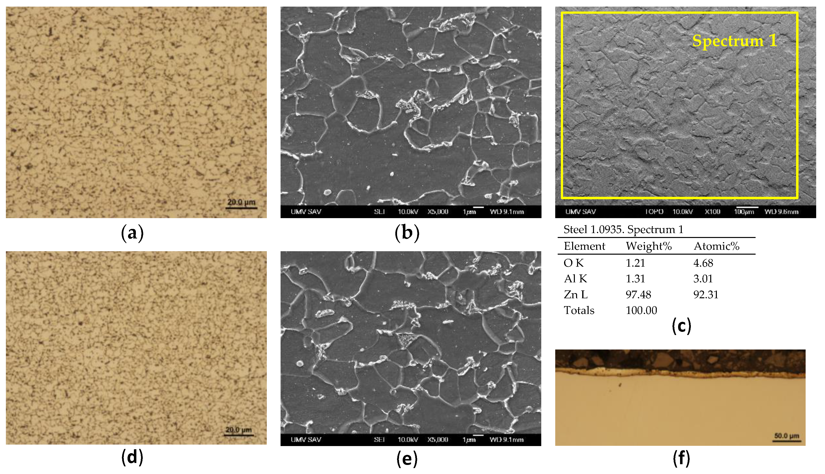
Figure 9.
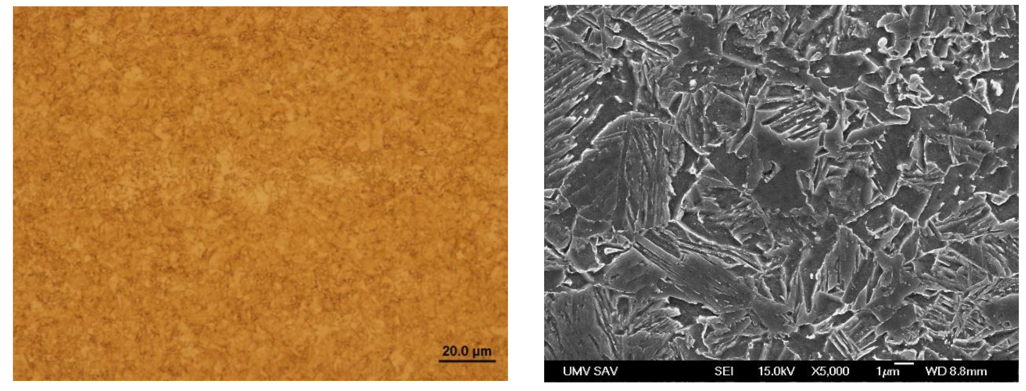
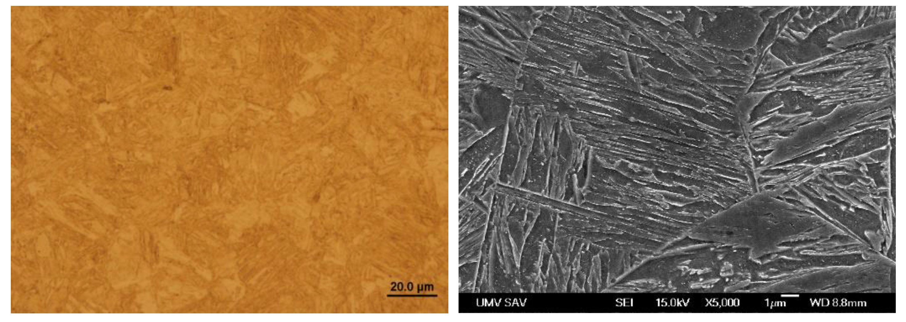
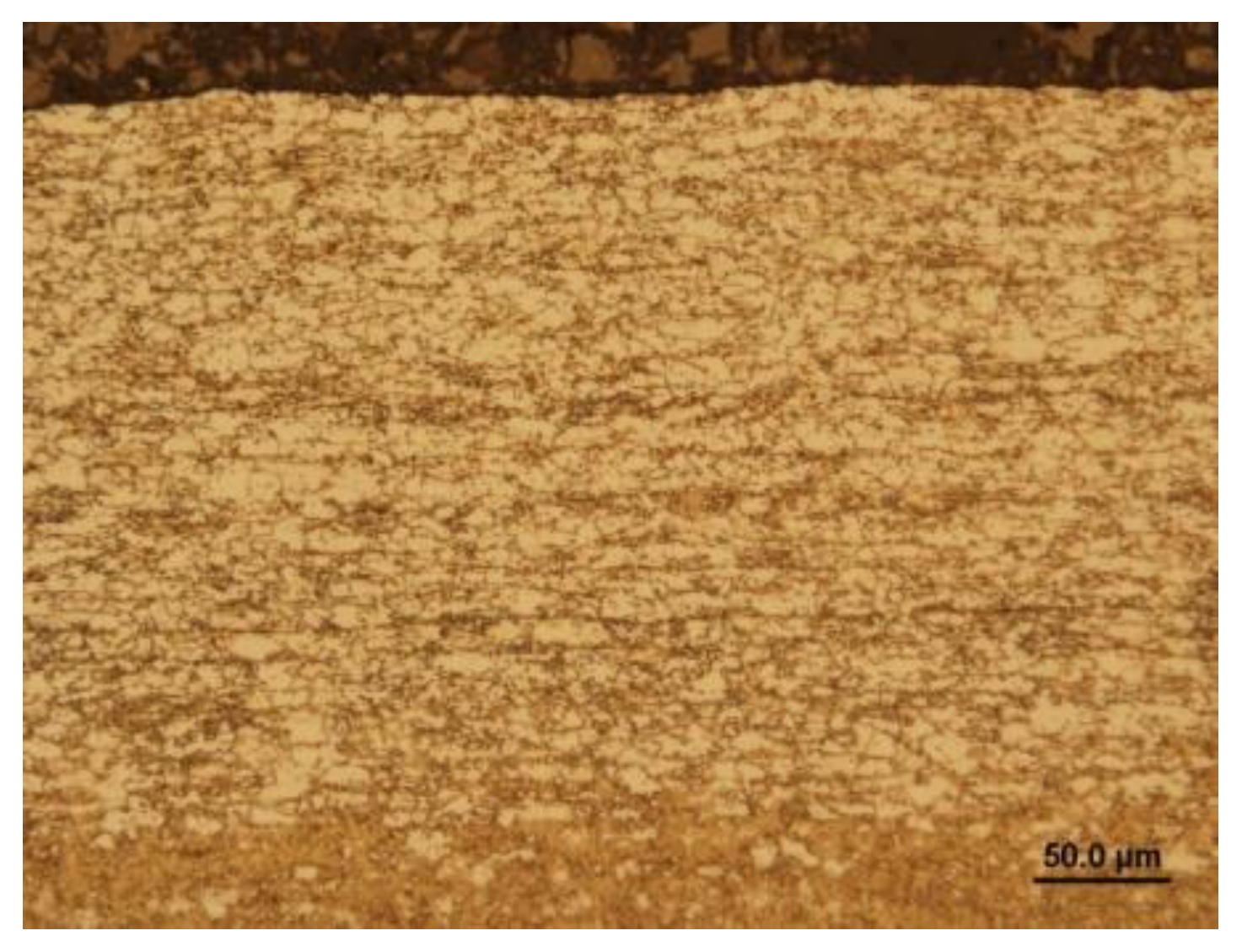
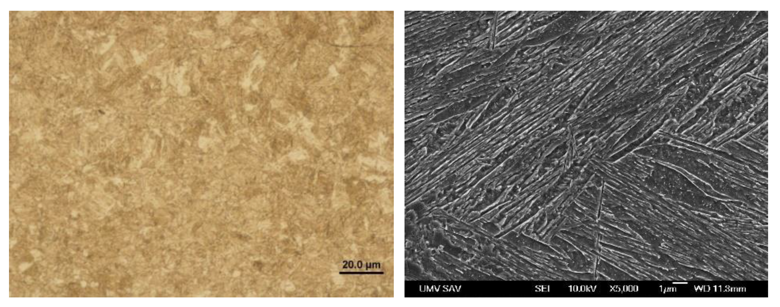
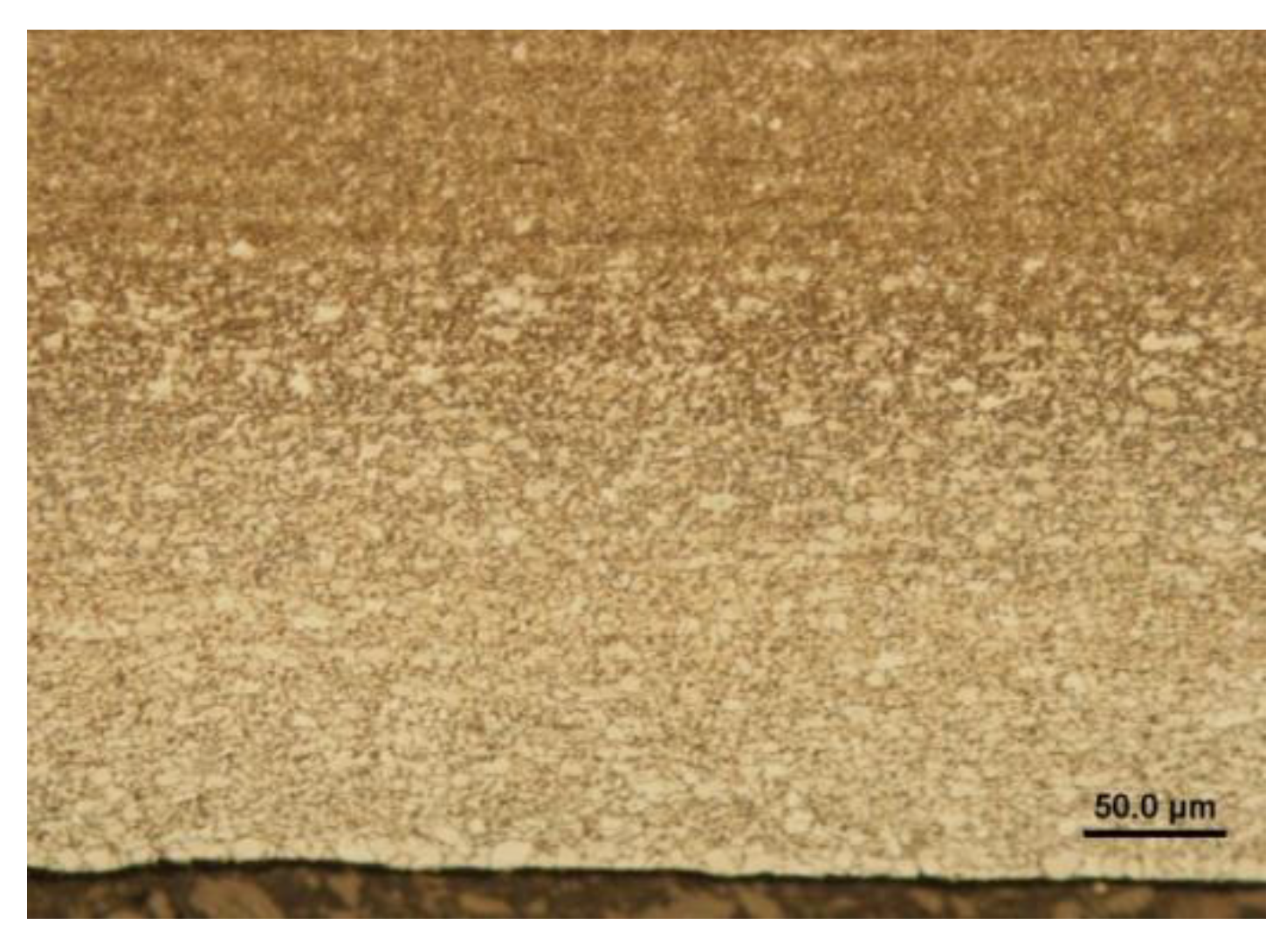
Steel 1.0935, h=1.5 mm, (a) microstructure in the rolling direction, light microscopy, (b) microstructure in the rolling direction, scanning electron microscopy, (c) stochastic topography of hot-dip galvanized surface and semi-quantitative EDX microanalysis - Spectrum 1, (d) microstructure perpendicular to rolling direction, light microscopy, (e) microstructure perpendicular to the rolling direction, (f) zinc layer profile.
Figure 10.
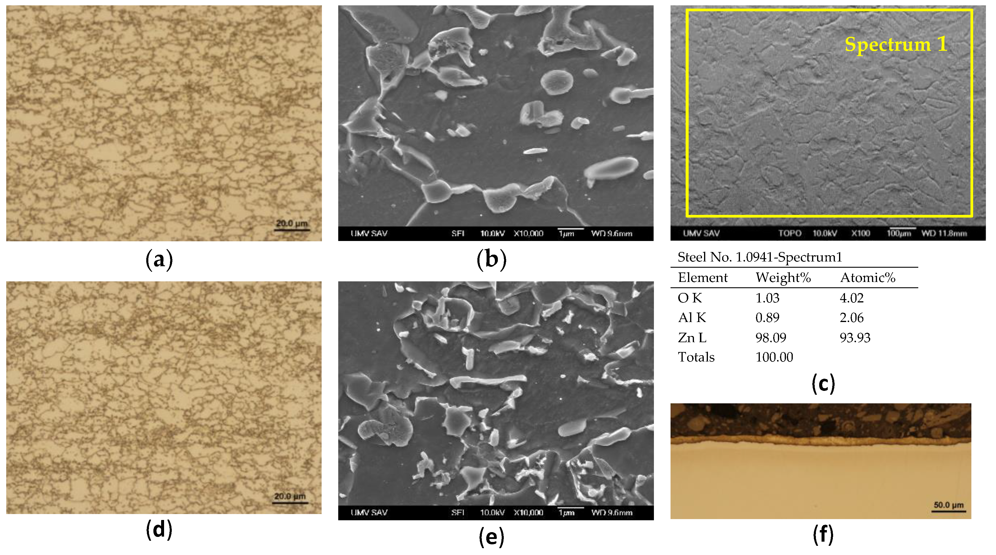
Steel 1.0941, h=1.5 mm, (a) microstructure in the rolling direction, light microscopy, (b) microstructure in the rolling direction, scanning electron microscopy, (c) stochastic topography of hot-dip galvanized surface and semi-quantitative EDX microanalysis - Spectrum 1, (d) microstructure perpendicular to rolling direction, light microscopy, (e) microstructure perpendicular to the rolling direction, (f) zinc layer profile.
Figure 11.
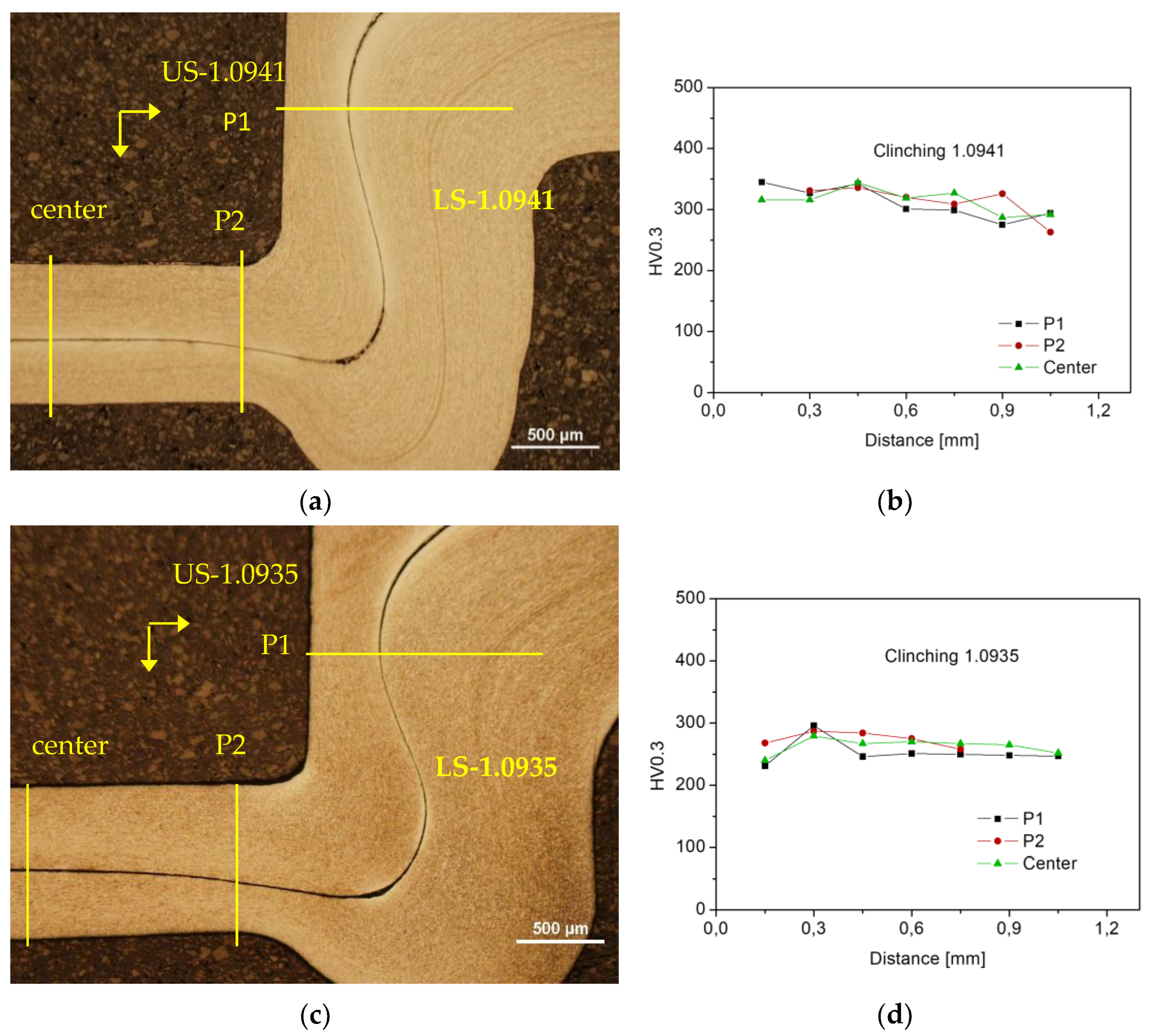
Profile of clinched joint, a) Steel No. 1.0941; b) Steel No. 1.0935.
Figure 11.
Profile of clinched joint, a) Steel No. 1.0941; b) Steel No. 1.0935.
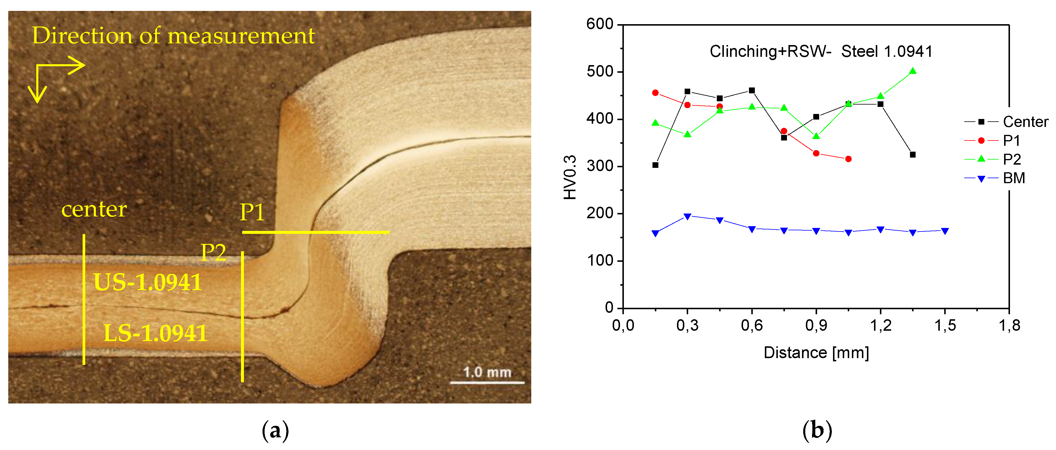
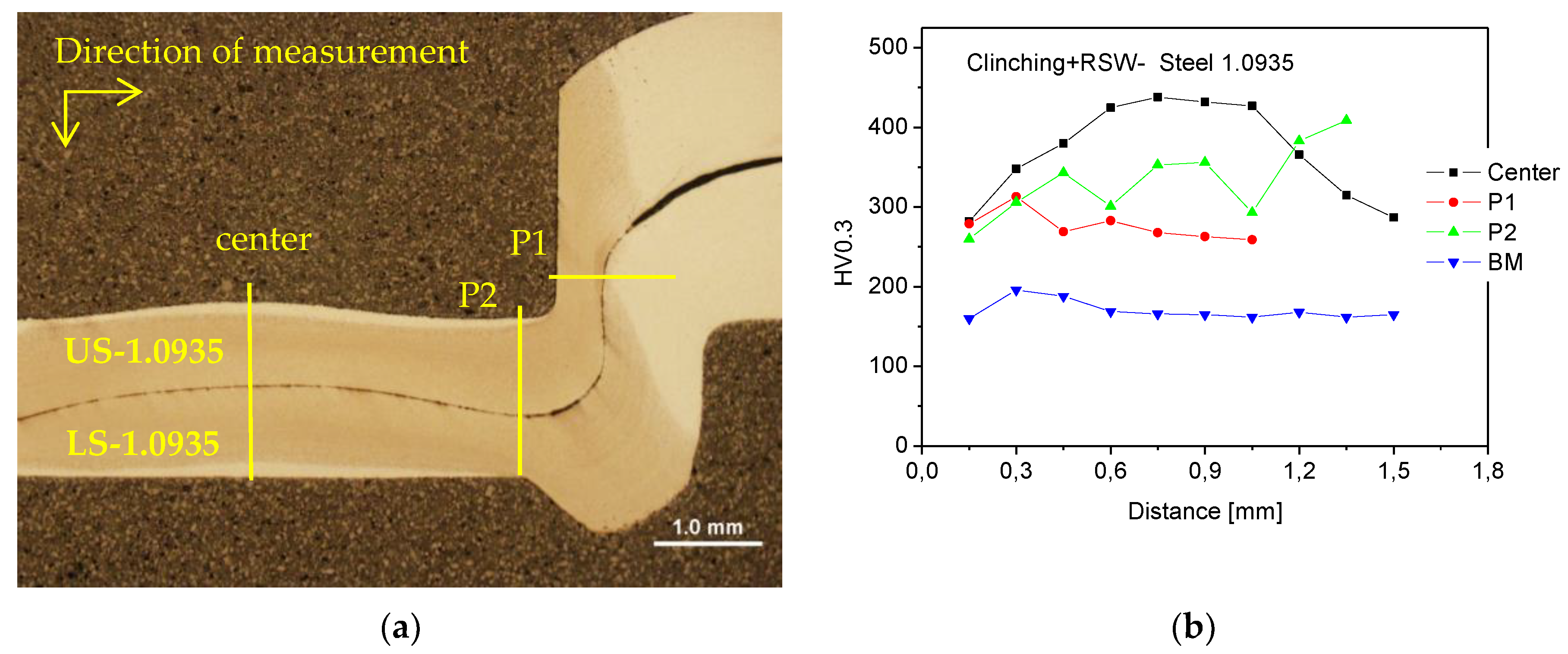
Figure 12.
Schematic of microhardness measurement HV0.3; (a) clinched joint - Steel No.1.0941, (b) HV0.3 in clinched joint of material No.1.0941 in P1, P2 and center directions, (c) clinched joint - Steel No.1.0935, (d) HV0.3 in clinched joint of material No.1.0935 in P1, P2 and center directions.
Figure 12.
Schematic of microhardness measurement HV0.3; (a) clinched joint - Steel No.1.0941, (b) HV0.3 in clinched joint of material No.1.0941 in P1, P2 and center directions, (c) clinched joint - Steel No.1.0935, (d) HV0.3 in clinched joint of material No.1.0935 in P1, P2 and center directions.
Figure 13.
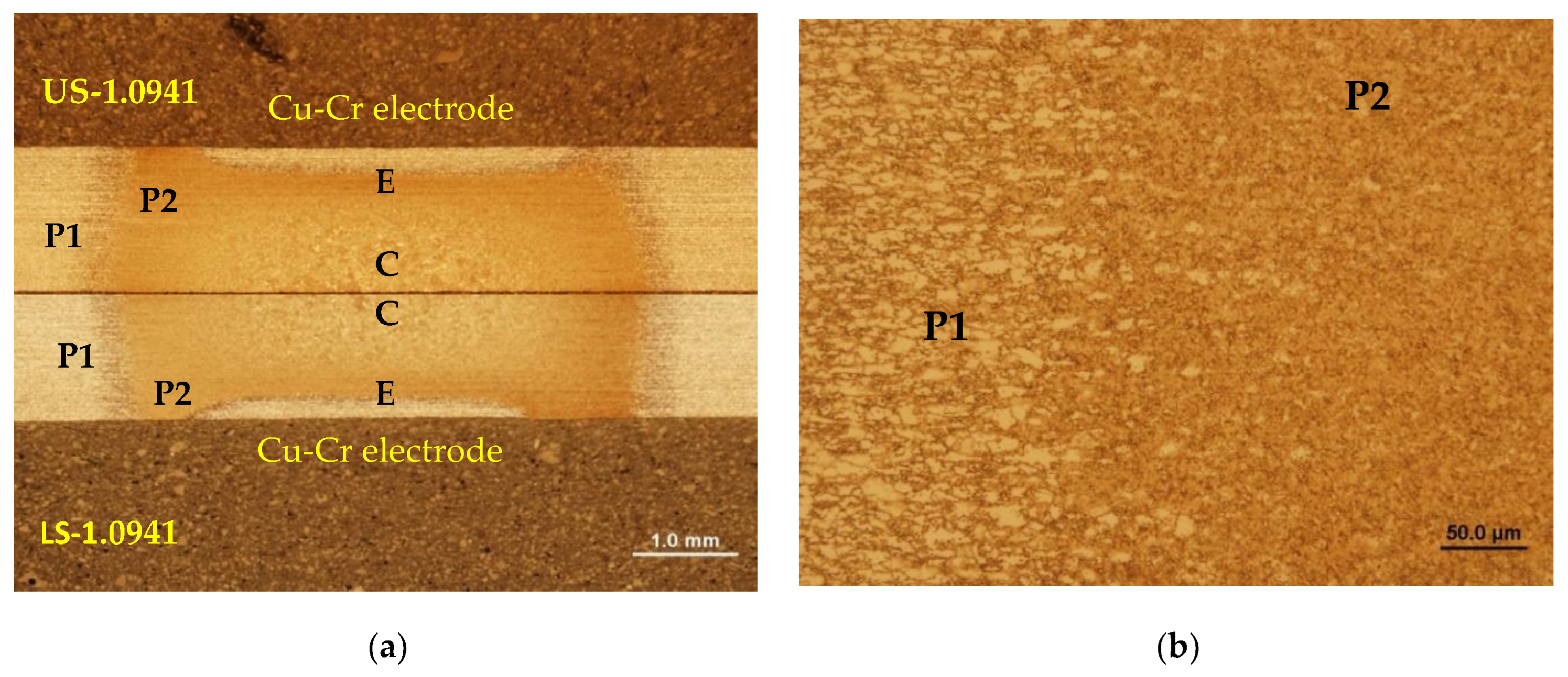
Microstructure of Steel No. 1.0941 in the heating zone: (a) defining the zones, (b) zones from P1 to P2.
Figure 13.
Microstructure of Steel No. 1.0941 in the heating zone: (a) defining the zones, (b) zones from P1 to P2.
Figure 14.
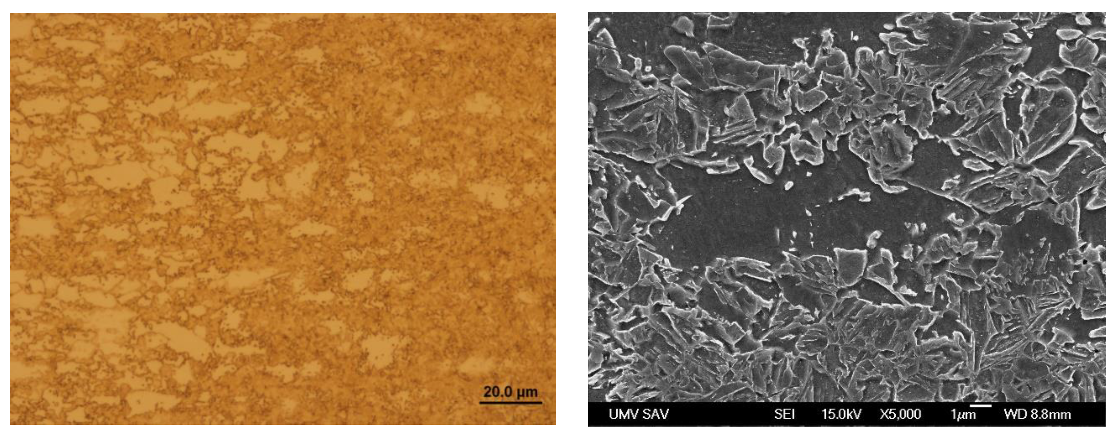
Microstructure in the local heating zone of Steel No. 1.0941 – zone P1.
Figure 14.
Microstructure in the local heating zone of Steel No. 1.0941 – zone P1.
Figure 15.
Microstructure in the zone P2 of Steel No. 1.0941.
Figure 15.
Microstructure in the zone P2 of Steel No. 1.0941.
Figure 16.
Microstructure in the zone C of Steel No. 1.0941.
Figure 16.
Microstructure in the zone C of Steel No. 1.0941.
Figure 17.
Microstructure in the zone E of Steel No. 1.0941.
Figure 17.
Microstructure in the zone E of Steel No. 1.0941.
Figure 18.
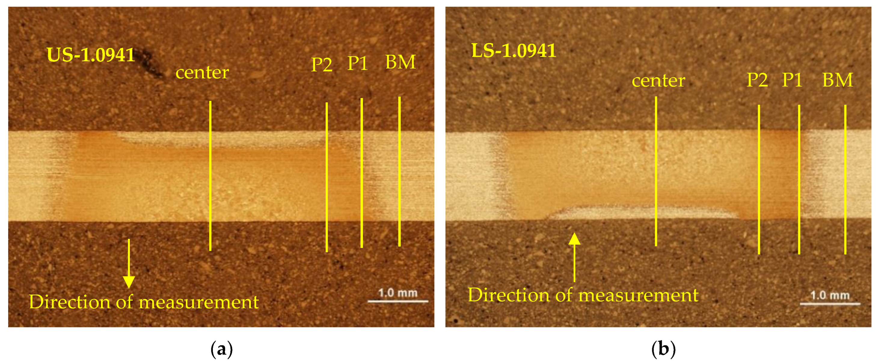
Microhardness measurement scheme (steel 1.0941): (a) upper sheet (US), (b) lower sheet (LS).
Figure 18.
Microhardness measurement scheme (steel 1.0941): (a) upper sheet (US), (b) lower sheet (LS).
Figure 19.
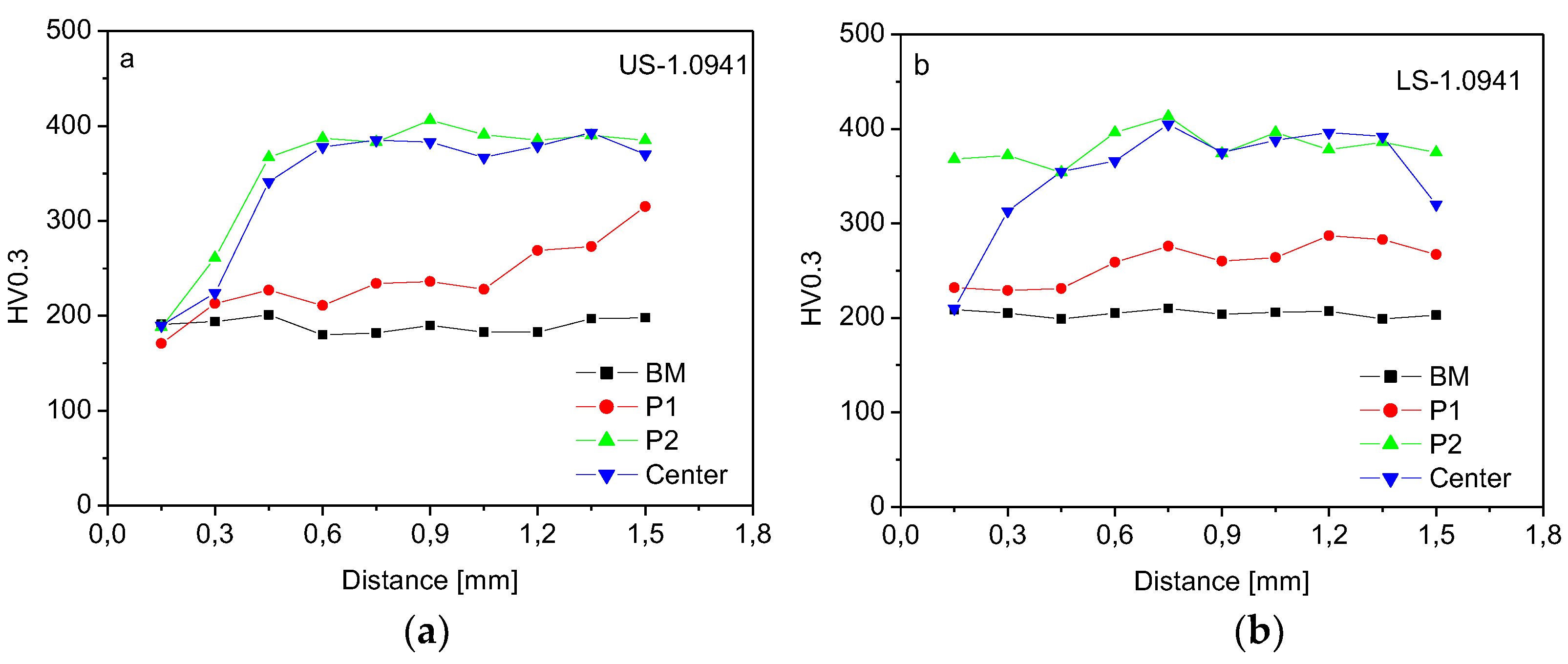
Microhardness HV0.3, zones with gradient microstructure of Steel 1.0941: (a) upper sheet (US), (b) lower sheet (LS).
Figure 19.
Microhardness HV0.3, zones with gradient microstructure of Steel 1.0941: (a) upper sheet (US), (b) lower sheet (LS).
Figure 20.
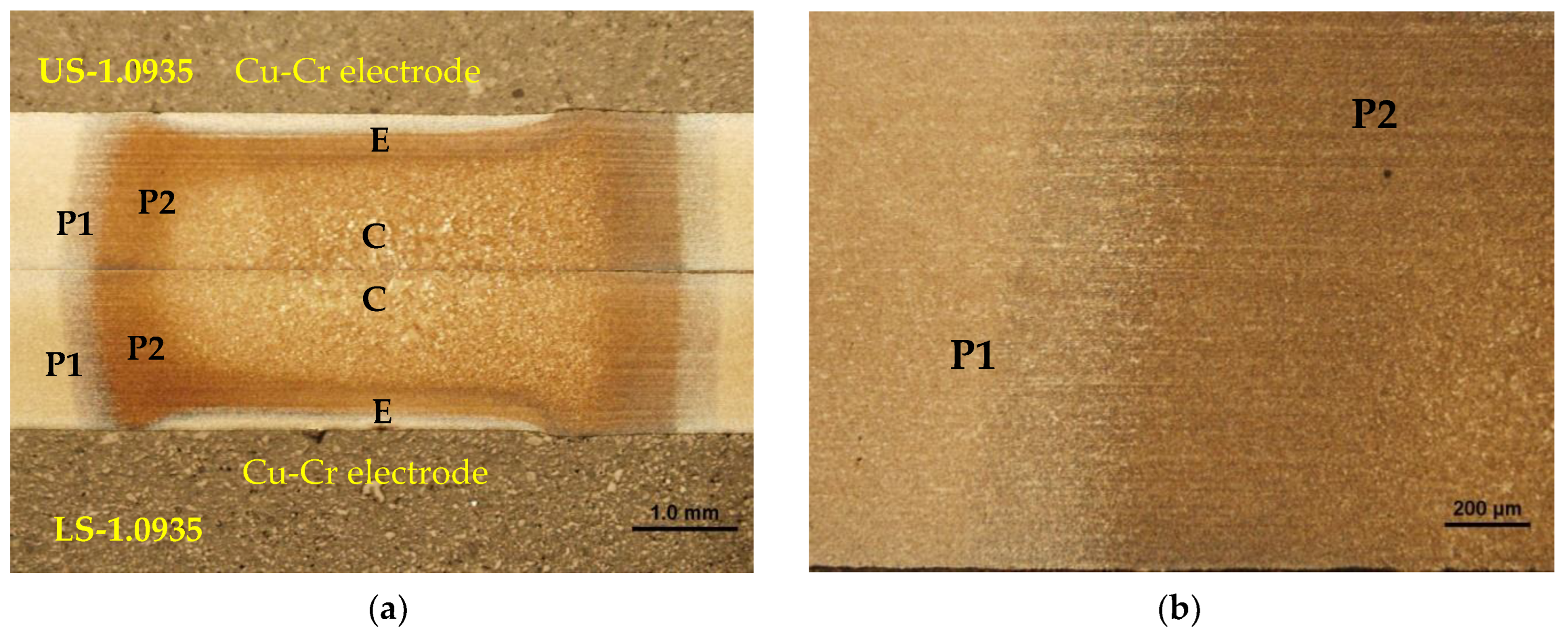
Microstructure of Steel No. 1.0935 in the heating zone: (a) defining the zones, (b) zones from P1 to P2.
Figure 20.
Microstructure of Steel No. 1.0935 in the heating zone: (a) defining the zones, (b) zones from P1 to P2.
Figure 21.
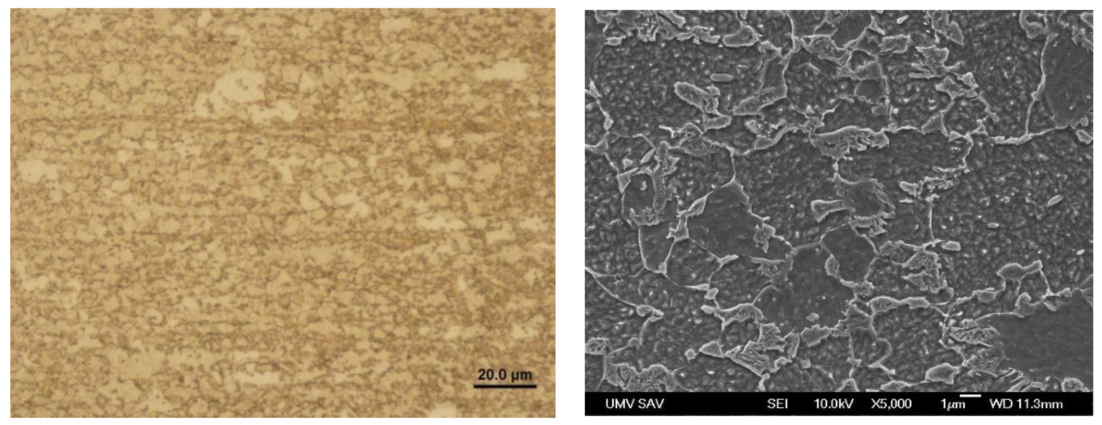
Microstructure in the local heating zone of Steel No. 1.0935 – zone P1.
Figure 21.
Microstructure in the local heating zone of Steel No. 1.0935 – zone P1.
Figure 22.
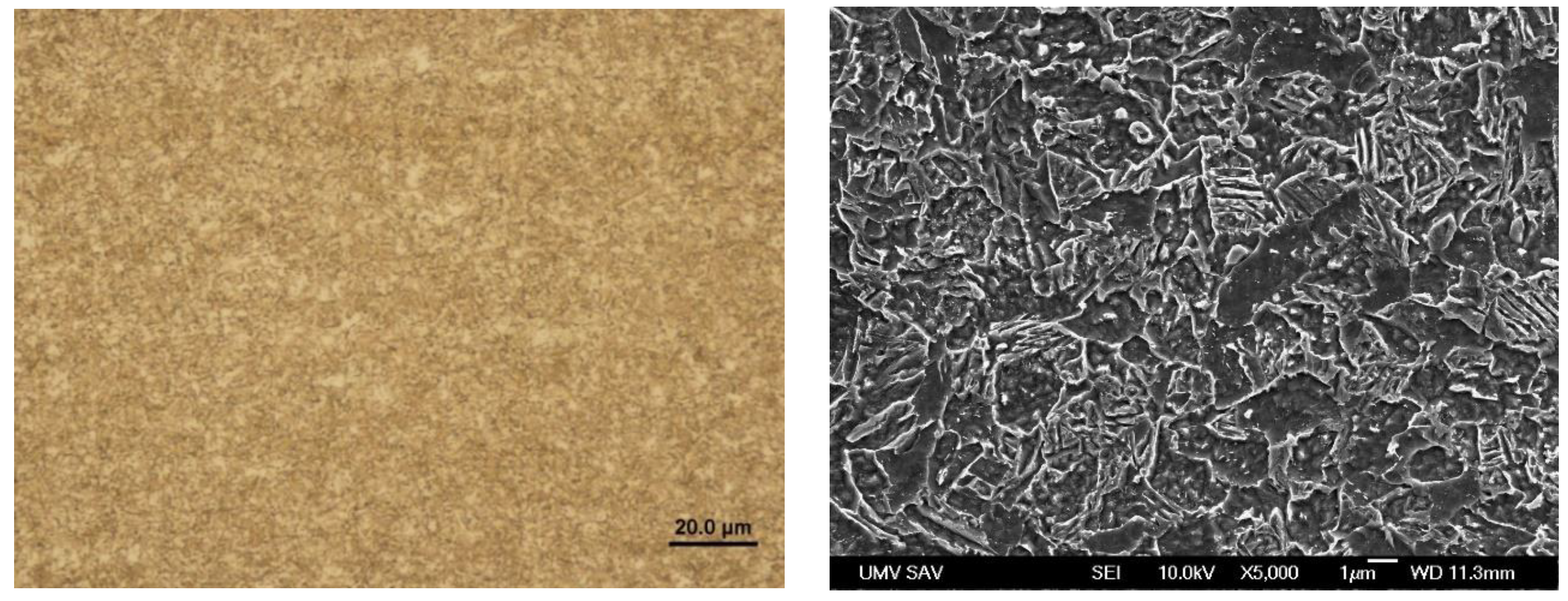
Microstructure in the zone P2 of Steel No. 1.0935.
Figure 22.
Microstructure in the zone P2 of Steel No. 1.0935.
Figure 23.
Microstructure in the zone C of Steel No. 1.0935.
Figure 23.
Microstructure in the zone C of Steel No. 1.0935.
Figure 24.
Microstructure in the zone E of Steel No. 1.0935.
Figure 24.
Microstructure in the zone E of Steel No. 1.0935.
Figure 25.
Microhardness measurement scheme (steel 1.0935): (a) upper sheet (US), (b) lower sheet (LS).
Figure 25.
Microhardness measurement scheme (steel 1.0935): (a) upper sheet (US), (b) lower sheet (LS).
Figure 26.
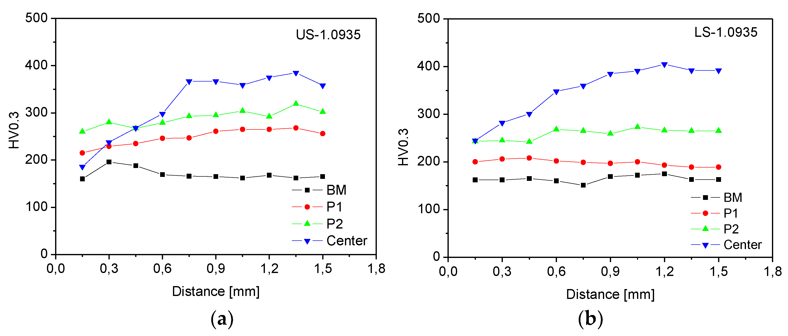
Microhardness HV0.3, zones with gradient microstructure of Steel 1.0935: (a) upper sheet (US), (b) lower sheet (LS).
Figure 26.
Microhardness HV0.3, zones with gradient microstructure of Steel 1.0935: (a) upper sheet (US), (b) lower sheet (LS).
Figure 27.
Preheated clinched joint on steels No. 1.0941: (a) measurement scheme HV0.3, (b) HV0.3 microhardness measurements.
Figure 27.
Preheated clinched joint on steels No. 1.0941: (a) measurement scheme HV0.3, (b) HV0.3 microhardness measurements.
Figure 28.
Preheated clinched joint on steels No. 1.0935: (a) measurement scheme HV0.3, (b) HV0.3 microhardness measurements.
Figure 28.
Preheated clinched joint on steels No. 1.0935: (a) measurement scheme HV0.3, (b) HV0.3 microhardness measurements.
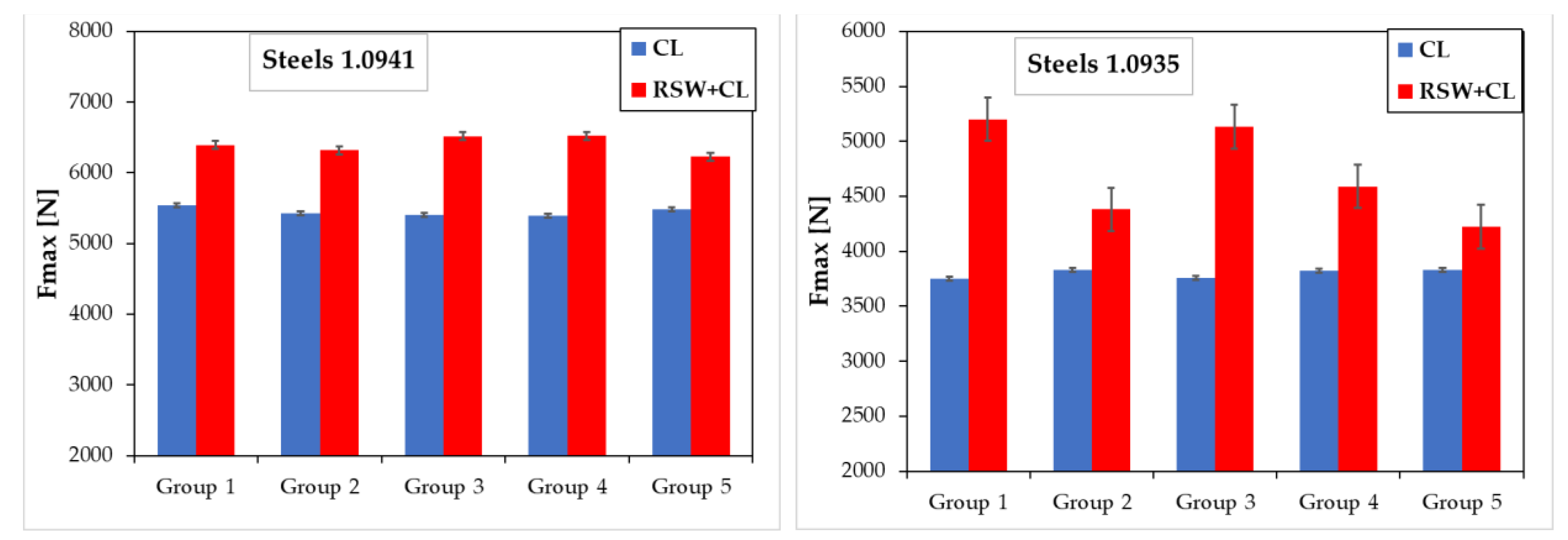
Figure 29.
Comparison of load-bearing capacity (Fmax) of clinched joints (CL) and preheated clinched joints (RSW+CL): (a) samples with steels No.1.0941, (b) samples with steels No.1.0935.
Figure 29.
Comparison of load-bearing capacity (Fmax) of clinched joints (CL) and preheated clinched joints (RSW+CL): (a) samples with steels No.1.0941, (b) samples with steels No.1.0935.
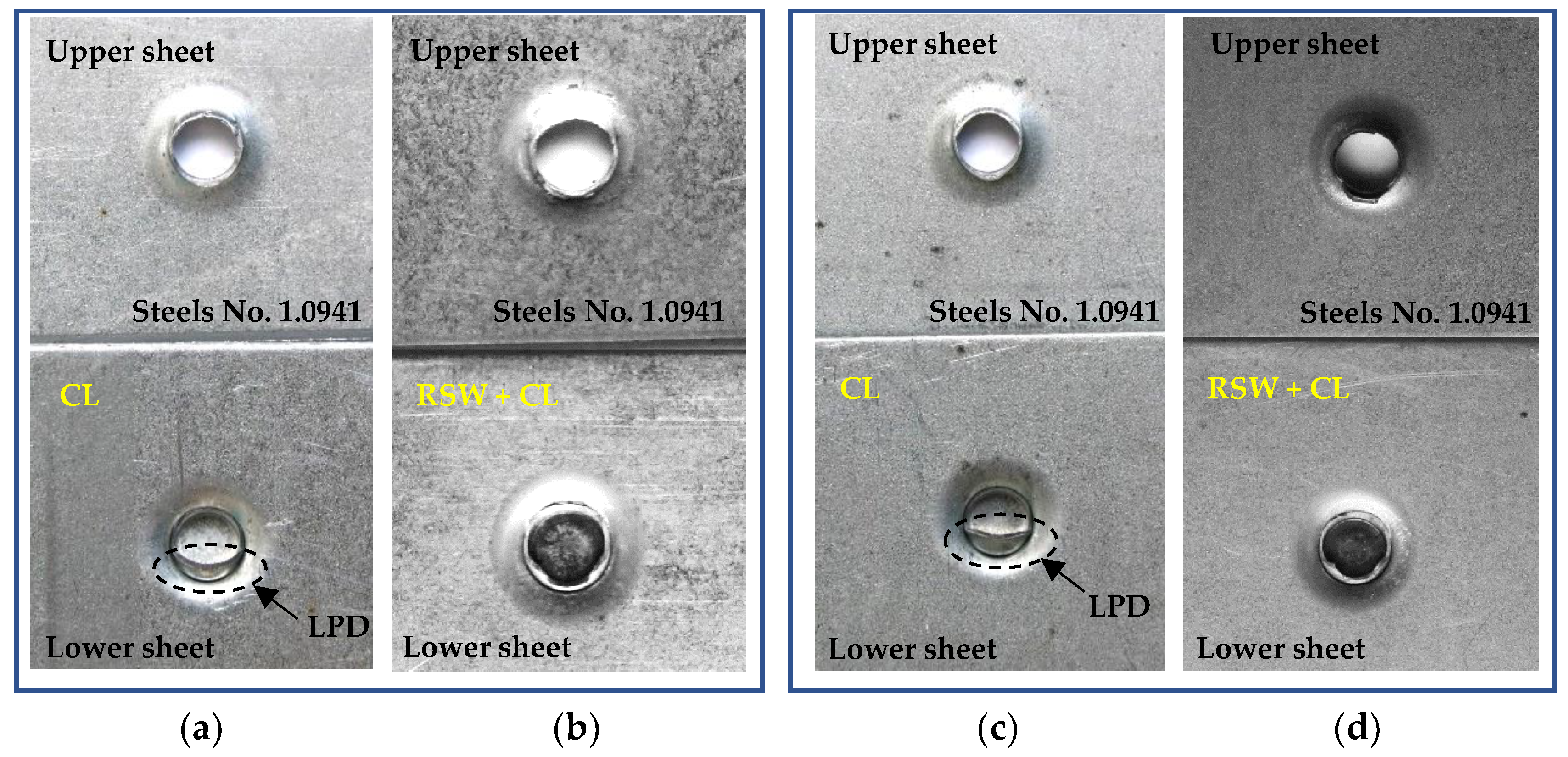
Figure 30.
Failure of joined samples after tensile test: (a) pure clinched joint (CL), steels No.1.0941, with local plastic deformation (LPD), (b) preheated clinched joint (RSW+CL), steels No.1.0941, (c) pure clinched joint (CL), steels No.1.0935, with local plastic deformation (LPD), (d) preheated clinched joint (RSW+CL), steels No.1.0935.
Table 1.
Chemical elemental composition of HCT600X+Z steel, No. 1.0941 [wt.%].
Table 1.
Chemical elemental composition of HCT600X+Z steel, No. 1.0941 [wt.%].
| C |
Mn |
Si |
P |
S |
Al |
Nb |
Cu |
Ni |
Cr |
Ti |
V |
Nb |
Mo |
| 0.075 |
1.880 |
0.016 |
0.015 |
0.005 |
0.055 |
0.003 |
0.022 |
0.009 |
0.208 |
0.001 |
0.003 |
0.003 |
0.170 |
Table 2.
Chemical elemental composition of HX420LAD+Z, No. 1.0935 [wt.%].
Table 2.
Chemical elemental composition of HX420LAD+Z, No. 1.0935 [wt.%].
| C |
Mn |
Si |
P |
S |
Al |
Nb |
Cu |
Ni |
Cr |
Ti |
V |
Nb |
Mo |
| 0.083 |
1.214 |
0.013 |
0.015 |
0.005 |
0.040 |
0.058 |
0.035 |
0.010 |
0.024 |
0.014 |
0.032 |
0.058 |
0.002 |
Table 3.
Mechanical properties and thicknesses of joined materials.
Table 3.
Mechanical properties and thicknesses of joined materials.
| Material |
Thickness [mm] |
Rp0.2 [MPa] |
Rm [MPa] |
A80
|
| HX420LAD+Z |
1.5 |
503 |
565 |
19.5 |
| HCT600X+Z |
1.5 |
343 |
593 |
27.5 |
