1. Introduction
Supercapacitors and lithium-ion batteries are widely used energy storage devices. Lithium-ion batteries achieve capacity by intercalating and deintercalating Li ions into and out of the crystal structure of the cathode and anode materials. On the other hand, supercapacitors achieve capacitance by adsorbing and desorbing ions from the electrolyte solution on the surface of activated carbon, which is an electrode material. The two energy storage devices have significant differences in their properties due to their different reaction mechanisms. Supercapacitors have low energy density, but their lifespan and output characteristics are significantly higher than those of lithium-ion batteries. Conversely, batteries have a much higher energy density compared to supercapacitors [
1,
2,
3,
4,
5,
6,
7,
8,
9,
10].
Supercapacitors have a voltage range of 0 to 2.7 volts, while the voltage range for lithium-ion batteries is typically between 3.0 to 4.2 volts. Supercapacitors have a high power density and can deliver high bursts of power. They also have a relatively short discharge time, typically on the order of a few seconds. Lithium-ion batteries, on the other hand, have a high energy density and can deliver power over a longer period of time, typically hours to days [
11,
12].
By combining supercapacitors and lithium-ion batteries, the resulting hybrid energy storage system can take advantage of the strengths of both technologies. The supercapacitors can provide high power density and fast discharge times, while the lithium-ion batteries can provide high energy density and longer discharge times. The voltage ranges of the two components can also be matched to allow for a smooth and efficient transfer of energy between the supercapacitors and lithium-ion batteries as needed.
Research to increase the lifespan of lithium-ion batteries by manufacturing a lithium-ion battery module and connecting supercapacitor modules in parallel to reduce the load on the lithium-ion battery is ongoing. This is because the reaction voltage of the individual cell of the supercapacitor and lithium-ion battery is different, so they are modularized and connected by matching their voltage. There is also a type of lithium-ion battery called a battery capacitor that is made of Li
4Ti
5O
12 (LTO) instead of graphite as the anode, which has excellent output and lifespan characteristics compared to graphite [
13,
14].
Most studies on combining supercapacitors and lithium-ion batteries are conducted at the module level, but battery capacitors have a similar voltage range to supercapacitors, allowing them to be connected in parallel between cells. This makes battery capacitor a candidate for transforming into a new type of energy storage device. By combining supercapacitors and battery capacitors, the system efficiency can be improved, and the lifetime characteristics can be improved by reducing the burden on the battery capacitor at high current. This results in a new energy storage device that is capable of both long-term energy storage and high power transmission. Additionally, the combination of supercapacitors and battery capacitors can provide high-performance energy storage while reducing the overall cost of an energy storage system [
15,
16,
17,
18,
19,
20,
21,
22,
23,
24].
It is important to note that the specific voltage range and discharge time for a hybrid energy storage system will depend on the specific components used, as well as the configuration of the system. However, in general, hybrid energy storage systems that combine supercapacitors and battery capacitors can offer improved performance and efficiency compared to using either technology alone.
In this study, we aim to investigate the improvement of system efficiency, reliability, performance, and cost-effectiveness by combining supercapacitors and battery capacitors in the same cell with a specific volume ratio.
2. Materials and Methods
2.1. Fabrication of Individual Cells
For the positive electrode of the battery capacitor, an electrode slurry was prepared by mixing two types of Li(Ni1/3Co1/3Mn1/3)O2 (NCM) and LiCoO2 (LCO) positive electrode active materials, with super-p serving as a conductive material and PVdF as a binder, in a mixing ratio of 87:6.5:6.5, and NMP used as a solvent. For the anode of the battery capacitor, a slurry was prepared using LTO as the active material and the same ratio of binder and conductive material as the cathode. The positive and negative electrodes were coated on etched Al foil with a thickness of 20 μm and subjected to a roll press to manufacture the positive and negative electrodes, with approximately 25% compression. The resulting electrodes were then formed into a jelly roll using a winding machine, dried at 145 °C for 48 hours, and impregnated with a 1.0M LiPF6 + EC/DMC/EMC electrolyte solution to assemble the cell.
The supercapacitor utilized activated carbon as the electrode active material, super-P as the conductive material, and a binder consisting of a mixture of CMC, SBR, and PTFE. The electrode slurry was prepared with a ratio of 80:10:10 for the active material, conductive material, and binder, respectively. The electrodes were coated on etched Al foil with a thickness of 20μm and produced by a roll press with approximately 15% compression. The fabricated electrodes were then formed into a jelly roll using a winding machine, dried at 145°C for 48 hours, and impregnated with a 1.0M TEABF4 + ACN electrolyte solution to assemble a cell.
2.2. Complex Cell Fabrication
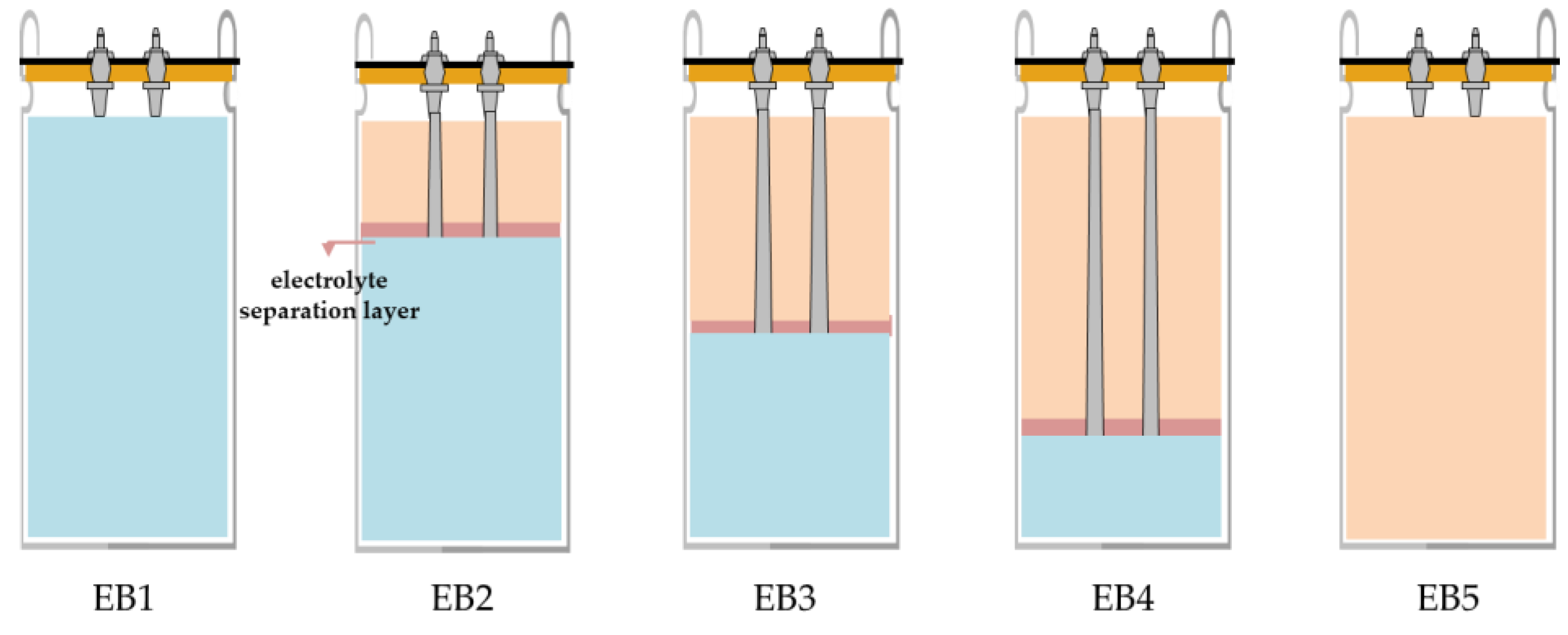
The electrolyte of the battery capacitor uses the LiPF6 salt, the supercapacitor uses the TEABF4 salt, and other types of solvents are also utilized. To connect the battery capacitor and the supercapacitor in parallel within a single cell, it is necessary to insert a separation layer to prevent the mixing of electrolytes. Urethane was selected as the separation layer material, as it was determined to be suitable due to the absence of any reaction when immersed in both the battery capacitor electrolyte and the supercapacitor electrolyte.
Figure 1 presents a schematic diagram of the combination of a battery capacitor and a supercapacitor, showing the volume ratio and capacity ratio. The battery capacitor have a capacity that is approximately 17 times higher than that of the supercapacitors at the same volume, resulting in differences in capacity among cells depending on the volume ratio. Single battery capacitor and supercapacitors that have not been combined will also be compared to composite cells.
2.3. Cell Evaluation
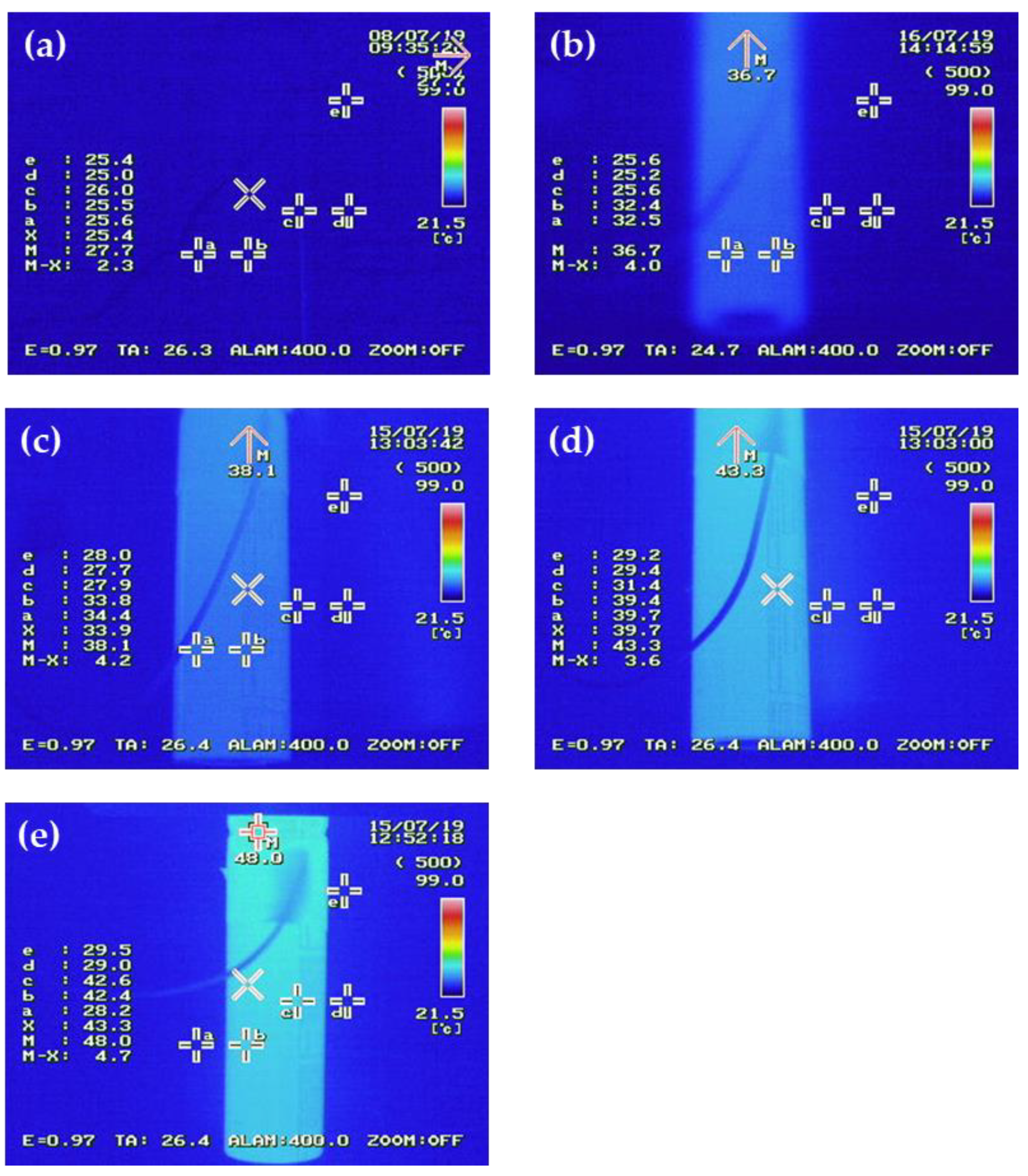
The characteristics of battery capacitor, supercapacitors, and composite cells were evaluated by examining their charge/discharge current at 1.5 to 2.7V at room temperature using an Arbin charger/discharger. A long-term life evaluation was also conducted at room temperature, with a current of 20C. During the evaluation of cell life with a current of 20C, the temperature of the cell was measured using a thermal imaging camera. To assess the current distribution to the battery capacitor and the supercapacitor during the charging and discharging process of the composite cell, it was measured using an oscilloscope.
3. Results
This section may be divided by subheadings. It should provide a concise and precise description of the experimental results, their interpretation, as well as the experimental conclusions that can be drawn.
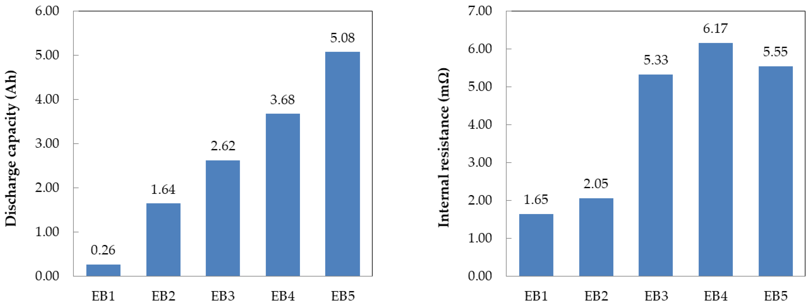
Figure 2 shows the capacitance and resistance of the individual battery capacitor and supercapacitor cells, as well as the composite cell, measured by applying a current of 1A at 2.7~1.5V. The composite cell’s capacity decreases as the volume ratio of the battery capacitor increases because the battery capacitor’s capacity is about 17 times larger than that of the supercapacitor. Additionally, the resistance of the composite cell decreases as the volume of the supercapacitor increases since the supercapacitor’s resistance is 25% of that of the battery capacitor.
Figure 3 illustrates the discharge curves of the individual battery capacitor and supercapacitor cells, as well as the composite cells. Supercapacitors exhibit a linear discharge curve that depends on the voltage since ions in the electrolyte are adsorbed/desorbed on the surfaces of the anode and cathode electrodes, resulting in low voltage drop due to low resistance. Conversely, battery capacitor have a flat section in their discharge curve since Li ions intercalate/deintercalate from the positive and negative electrode materials at a specific voltage, instead of a linear discharge curve [
25]. The initial voltage during discharge increases as the volume ratio of the supercapacitor increases in the composite cell. This occurs because the battery capacitor changes to a supercapacitor discharge curve in the initial discharge voltage range due to low energy.
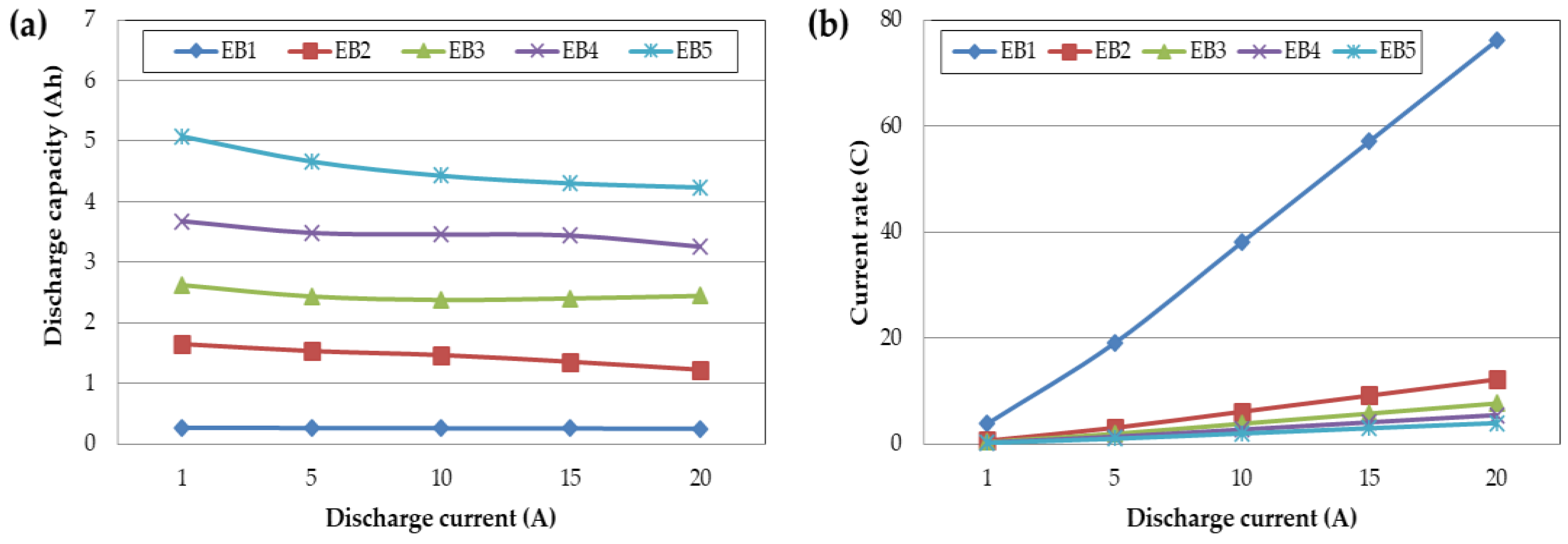
Figure 4 presents the rate of change in capacity and resistance of the individual Battery capacitor and supercapacitor cells, as well as the composite cells, with respect to the applied current. The capacity change rate tended to decrease as the current increased, and the rate of change in resistance decreased, except for the supercapacitor cells alone. It was confirmed that the capacity change rate increased as the volume ratio of the supercapacitor increased in the composite cell, where a battery capacitor and a supercapacitor were combined. The high output characteristics of the supercapacitor are believed to assist the output characteristics of the battery capacitor at high current.
The individual and composite cells of the battery capacitor and supercapacitor were manufactured to the same size and assembled with different internal volume ratios. When evaluated at a charge/discharge current of 1~20A, the current received per volume is the same. However, when compared by the cell capacity, a cell made of only supercapacitors receives 76.09C at 20A, whereas a battery capacitor receives 3.94C. Even though the received current per volume is the same, since the capacity differs according to the volume ratio of the composite cell, the current received in terms of capacity may vary significantly.
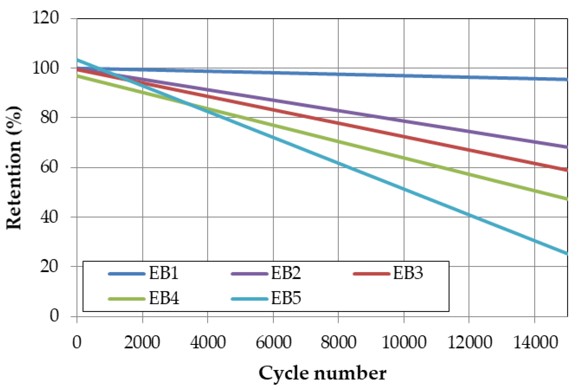
In order to evaluate the lifespan characteristics of the battery capacitor and supercapacitor individual cells and composite cells, a life evaluation was conducted at room temperature with a current of 20C, as shown in
Figure 6. The results showed that the number of cycles at which the capacity retention rate is less than 80% compared to the initial capacity during charging/discharging with the battery capacitor 20C is about 4200 cycles. However, when the supercapacitor is added to the composite cell according to the volume ratio, the number of cycles at which the capacity retention rate is less than 80% increases. One of the main factors contributing to the increased lifespan of the battery capacitor combined with a supercapacitor is the amount of heat generated from the cells.
The temperature of the cell during the cycle evaluation was measured with a thermal imaging camera, and is shown in
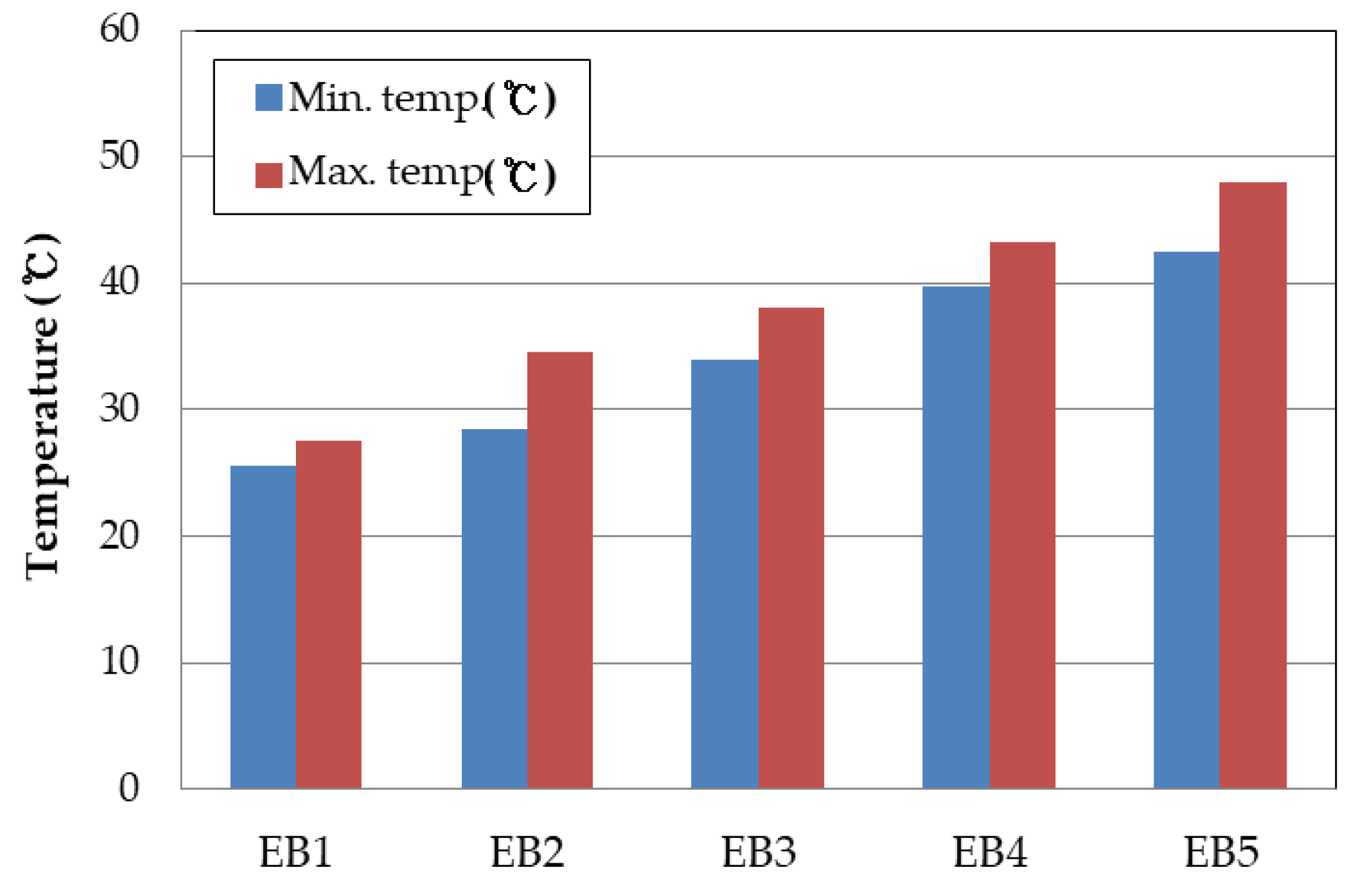
Figure 7. During the life evaluation, the surface temperature of the cell using only the battery capacitor was measured at 43 to 48 °C, while the temperature at the jelly roll stage was estimated to be higher than 60°C, indicating a temperature difference of approximately 15°C between the surface and inside of the cell. Since the temperature of the cell is one of the biggest factors affecting its lifespan characteristics, combining it with the supercapacitor led to a decrease in temperature during the charge/discharge process, and consequently, an improvement in lifespan characteristics.
To investigate the current behavior during charging and discharging of a parallel-connected battery capacitor and supercapacitor, we measured individual currents using an oscilloscope and presented the results in
Figure 9 and
Table 2. During charging, the supercapacitor initially accepted current at a high rate, and the charging current gradually decreased over time. In contrast, the battery capacitor did not initially accept the charging current, but we confirmed that it increased over time. According to the current distribution law, initially most of the charging current flowed into the supercapacitor due to its low resistance, but as the supercapacitor became charged, the charging current shifted towards the battery capacitor. By absorbing the initial surge of current during charging and discharging, the supercapacitor can reduce the damage to the battery capacitor, which gradually receives the current [
26].
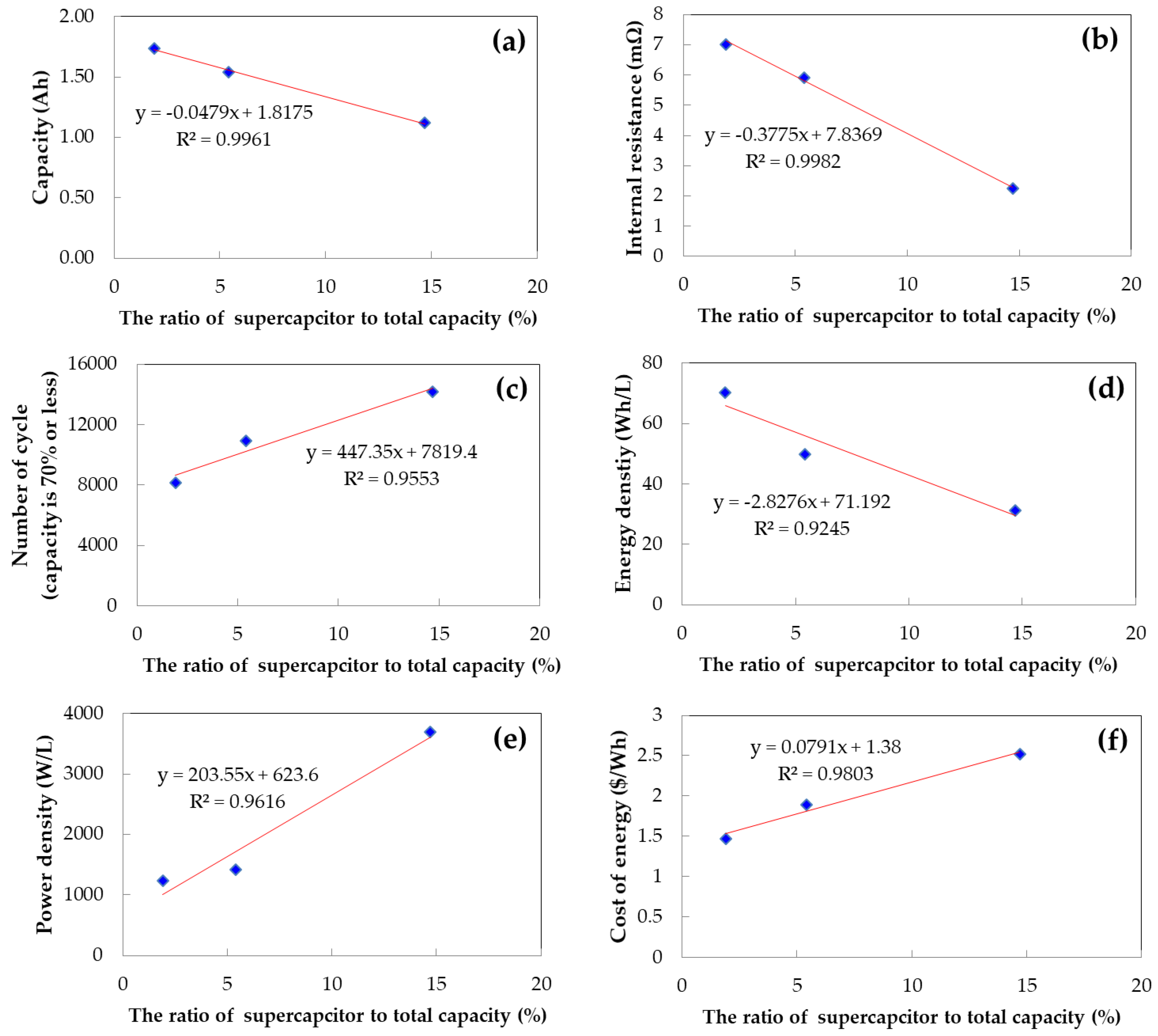
Figure 10 presents the electrical characteristics of the composite cell as a function of the volume ratio of the supercapacitor and battery capacitor, based on our measurements. As the volume occupied by the supercapacitor increases in the composite cell, the capacity, resistance, and energy density per unit volume tend to decrease, while the lifespan, output characteristics, and cost for energy storage tend to increase. Due to the different characteristics of the supercapacitor and battery capacitor, the composite cell exhibits various electrical characteristics depending on the volume ratio. Consequently, it is possible to design a new type of energy storage device with complementary characteristics by adjusting the volume ratio of the components.
4. Discussion
The conclusion of the dissertation proposes the development of a new type of energy storage device through internal parallel connection of two different types of energy storage devices. The study shows that supercapacitors and battery capacitors can complement each other’s characteristics when compounded, with the battery capacitor affecting energy improvement and the supercapacitor affecting resistance and lifespan characteristic improvement. The volume ratio of the two storage devices affects the characteristics of the complex cell, and the study allows for the quantification of the capacity, resistance, lifespan, energy density, power density, and cost of a composite cell based on the volume ratio. This enables the design of new energy storage devices suitable for applications and will play an important role in the field.
Author Contributions
Conceptualization, J. K. L and J. R. Y.; methodology, J. K. L and J. R. Y.; software, J. K. L.; validation, J. K. L and J. R. Y; formal analysis, J. K. L and J. R. Y.; investigation, J. K. L and J. R. Y.; resources, J. K. L and J. R. Y.; data curation, J. K. L and J. R. Y.; writing—original draft preparation, J. K. L.; writing—review and editing, J. K. L and J. R. Y.; visualization, J. K. L.; supervision, J. K. L and J. R. Y.; project administration, J. K. L and J. R. Y.; funding acquisition, J. K. L and J. R. Y. All authors have read and agreed to the published version of the manuscript.
Funding
This work was supported by the Technology Innovation Program (10062226, The development of battery capacitor (58Wh/L) composed of graphene and lithium transition metal oxide based flexible electrode for IoT device) funded By the Ministry of Trade, Industry & Energy (MOTIE, Korea)
Data Availability Statement
Data available on request.
Conflicts of Interest
The authors declare no conflict of interest.
References
- Cheng, F.; Chen, J.; Liang, J. Functional materials for rechargeable batteries, vs. supercapacitors. Progress in Materials Science 2011, 56, 917–1013. [Google Scholar]
- Chmiola, J.; Yushin, G.; Gogotsi, Y.; Portet, C.; Simon, P.; Taberna, P. L. Anomalous increase in carbon capacitance at pore sizes less than 1 nanometer. Science 2006, 313, 1760–1763. [Google Scholar] [CrossRef] [PubMed]
- Huang, Y.; Zhu, M.; Zhu, K.; Yang, Q. H.; Wang, J. Mechanisms of pseudocapacitive energy storage in transition metal oxides/hydroxides. Advanced Energy Materials 2015, 5, 1500930. [Google Scholar]
- Miller, J. R.; Simon, P. Electrochemical capacitors for energy management. Science 2008, 321, 651–652. [Google Scholar] [CrossRef] [PubMed]
- Xu, J.; Wang, X.; Shen, P. K. Recent progress on 2D materials for supercapacitor electrodes: From rational synthesis to electrochemical performance. Advanced Energy Materials 2017, 7, 1700626. [Google Scholar]
- Larcher, D.; Tarascon, J. M. Towards greener and more sustainable batteries for electrical energy storage. Nature Chemistry 2015, 7, 19–29. [Google Scholar] [CrossRef] [PubMed]
- Gogotsi, Y.; Simon, P. True performance metrics in electrochemical energy storage. Science 2011, 334, 917–918. [Google Scholar] [CrossRef] [PubMed]
- Augustyn, V.; Simon, P.; Dunn, B. Pseudocapacitive oxide materials for high-rate electrochemical energy storage. Energy and Environmental Science 2014, 7, 1597–1614. [Google Scholar] [CrossRef]
- Pandolfo, A. G.; Hollenkamp, A. F. Carbon properties and their role in supercapacitors. Journal of Power Sources 2006, 157, 11–27. [Google Scholar] [CrossRef]
- Simon, P.; Gogotsi, Y. Materials for electrochemical capacitors. Nature Materials 2013, 7, 845–854. [Google Scholar] [CrossRef]
- Khalid, M. A Review on the Selected Applicaiotns of Battery-Supercapacitor Hybrid Energy Storage Systems for Microgrids. Energies 2019, 12, 4559–4593. [Google Scholar] [CrossRef]
- Kouchachvili, L.; Yaici, W. Entchev, Hybrid battery/supercapacitor energy storage system for the electric vehicles. Journal of Power Sources 2018, 374, 237–248. [Google Scholar] [CrossRef]
- Chen, Q.; Li, Y.; Wang, Q.; Li, X. A comparative study of Li4Ti5O12 and graphite anodes for high-performance lithium-ion batteries. Journal of Power Sources 2015, 274, 823–829. [Google Scholar]
- Zhang, X.; Lu, L.; Liu, G. Comparative study of graphite and Li4Ti5O12 anodes for lithium-ion batteries. Journal of Power Sources 2009, 189, 867–870. [Google Scholar]
- Li, Z.; Li, J.; Liang, J.; Li, Y.; Li, X.; Li, Z.; Wang, Q. A review of the research progress on composite energy storage systems based on supercapacitors and batteries. Renewable and Sustainable Energy Reviews 2019, 103, 267–291. [Google Scholar]
- Liang, Y.; Xu, Z.; Yang, L.; Zhang, L. A review of composite energy storage system based on supercapacitors and batteries. Journal of Power Sources 2020, 472, 228499. [Google Scholar]
- Yang, C.; Chen, X.; Huang, Y.; Chen, Z. A review of hybrid energy storage systems based on supercapacitors and batteries. Sustainable Energy Technologies and Assessments 2017, 20, 14–29. [Google Scholar]
- Gu, H.; Wang, H.; Chen, Z.; Lin, L.; Guo, X. Enhanced electrochemical performance of supercapacitor by hybridizing with lithium-ion battery. Electrochimica Acta 2018, 283, 1478–1484. [Google Scholar]
- Xiong, J.; Wang, H.; Liu, Y.; Lin, H.; Wang, X. Synergetic effects of hybridizing supercapacitors and batteries in energy storage. Applied Energy 2018, 211, 702–716. [Google Scholar]
- Saeed, S.; Liu, Z.; Li, X.; Jiao, K. Recent advances in hybrid energy storage systems based on supercapacitors and batteries: A review. Renewable and Sustainable Energy Reviews 2021, 135, 110153. [Google Scholar]
- Wang, H.; Gu, H.; Chen, Z.; Guo, X. Review on the research progress of hybrid supercapacitor–battery energy storage system. Energy Technology 2019, 7, 1900399. [Google Scholar]
- Wang, Y.; Zhou, Q.; Ma, X.; Zhang, J.; Li, W.; Li, G. A review on hybrid energy storage systems combining battery and supercapacitor. Energy Conversion and Management 2019, 197, 111961. [Google Scholar] [CrossRef]
- Lota, G.; Zhao, X.; Zou, L. Recent advances in hybrid supercapacitors: A brief review. Nano Energy 2015, 13, 574–583. [Google Scholar]
- Huang, J.; Wu, J.; Zeng, X.; Zhang, B.; Hu, J. Recent advances in hybrid supercapacitor-battery systems for energy storage. Journal of Energy Storage 2019, 25, 100831. [Google Scholar]
- Zhang, J.; Shang, Y.; Hu, M.; Zhang, Y.; Wang, H.; Ma, J. Analysis of the charging and discharging characteristics of a lithium-ion battery-supercapacitor hybrid energy storage system. Journal of Power Sources 2018, 387, 66–73. [Google Scholar]
- Wang, W.; Luo, J.; Li, J.; Chen, J. Investigation of the current distribution in a hybrid energy storage system combining supercapacitors and batteries. Journal of Power Sources 2014, 247, 489–495. [Google Scholar]
|
Disclaimer/Publisher’s Note: The statements, opinions and data contained in all publications are solely those of the individual author(s) and contributor(s) and not of MDPI and/or the editor(s). MDPI and/or the editor(s) disclaim responsibility for any injury to people or property resulting from any ideas, methods, instructions or products referred to in the content. |
© 2024 by the authors. Licensee MDPI, Basel, Switzerland. This article is an open access article distributed under the terms and conditions of the Creative Commons Attribution (CC BY) license (https://creativecommons.org/licenses/by/4.0/).
