1. Introduction
The problem of tracking signals in DC-DC converters, specially the tracking of sinusoidal signals is of great importance due to the potential applications, particularly in UPS systems, where it is important to have signals with zero or at least a very small error between the reference and the output signals. However, the inherent dynamical nonlinearities of the converters provides a variety of challenges, for instance, the tracking of sinusoidal signals with exactly zero error between the outputs and the reference signal. To this end, it is highly important to design or redesign the standard typologies of the converters and design a controller to achieve the control or tracking objectives.
A common feature in the controller design process is to find the unstable tracking dynamics, i.e., systems whose internal dynamics becomes unstable when the outputs follow a given reference. The indirect control technique consists in considering another output for which the internal dynamics become stable. In this scenario other problem occurs, that is, computing the reference target for the new output. Such problem and the control technique is commonly found in the context of power converters. For the justification of current mode regulation and the use of indirect control in boost and buck boost converters [
1]. In [
2,
3] a current reference independent of a parameter where exist load disturbance is obtained, and it is used an adaptive control for the sinusoidal tracking for the current inductor. An inverted topology DC-DC capable of giving a voltage larger than the input is reported in [
4]. In [
5] a method known as stable inversion and robust tracking control are applied to the boost and buck-boost converters. A way to obtain a trigonometric approximation to the unstable periodic solution, needed for the tracking problem for which the harmonic balance method is used, is applied in [
6] where the use of an adaptive scheme to eliminate load disturbance and sliding mode control is applied. For an overview on power converters the reader is referred to [
7]. A generalized model for the buck-boost power converter in the state space is presented in [
8]. In addition to the above discussed, it is well known that the DC-DC converters are a key device in applications of medium voltage in smart grids [
9], also used in renewable energy applications [
10], solar energy system applications [
11] and electric vehicles [
12] among others, which is the importance of study their control.
In this note we consider the problem of tracking a sinusoidal reference voltage
by the output voltage of the converter in a new boost and buck-boost topology. A stable nonlinear system is determined to obtain the necessary inputs to follow the reference signal, exactly; to this end, a boost and buck-boost topology is designed to obtain two degrees of freedom in the input space, these topology are showed in the
Figure 1. The paper is organized as follows: In Section II, the model of the converter is obtained and the conditions on which the currents of the inductors follow a reference with zero error are derived; in Section III, simulation results are given. Finally, in the last section we draw some conclusions and future works.
2. Problem statement and model description
2.1. Problem statement
The main problem to attend consists in to control a DC-DC converter in such a way that the voltage output tracks exactly (tracking error ) a sinusoidal signal. However, it is well known that a second harmonic is produced in the output when a standard power DC-DC converters (one control input) tracks a sinusoidal reference. Therefore, it is desirable to eliminate or cancel the the second harmonic signal and obtain zero error in the tracking output signal. The new topology consists into aggregate a second stage to the standard converter, in such manner that the output of the second converter is connected to the load to cancel out the second harmonic.
The dynamical model for a single DC converter have the following model
Multiplying the first equation in (
1) by
x and the second equation in (
1) by
, the following differential equation is obtained.
The objective is that the output voltage
tracks a sinusoidal signal, however, note that from (
2) the product of the output produces a second harmonic. The proposed control in [
2] and [
3] produces that the current tracks the reference with zero error, whereas, the voltage has the component of the second harmonic and tracks the reference with error.
From eq. (
2) when
in steady state and the reference signal for the current is given by first equation in (
3) then the solution of eq. (
2) is not possible since produces inconsistent nonlinear simultaneous equations to determine the parameters. This is, in the left hand side of eq. (
2) produces second harmonics, then to solve the equation it is necessary a term of second harmonic in the right hand side, however, there are only three parameters in the right hand side and it is not possible to determine the solution of the equations. Now, if one propose an extra harmonic, then the products in the right hand sides produces more harmonics, therefore this procedure generates an infinite number of harmonics. Then, the topologies used in [
1,
2,
3,
6], only contain one DOF (degree of freedom), using the harmonic balance method, results in inconsistent, it implied neglecting some equations [
1], thus, the reference current in [
1,
2,
3,
6] are taken as
Departing from the mathematical model of the converter eq. (
2) the problem is to find a control input such that
where
is a sinusoidal signal reference, from the above discussion it is not possible since the product of sinusoidal signals increases the number of harmonics. In order to tackle this problem a second control input is required by means of a new topology.
2.2. Model Description
The main objective of this proposal is to control a DC-DC converter in order to track sinusoidal signals without second harmonic, to this end, an improvement of the Boost and Buck-Boost topologyes is performed. The main idea consist in to generate a second current
that permits to have a second degree of freedom and therefore a second control input that cancel the second harmonic produced by the model, [
1,
2].
The new boost and buck boost converters circuits are presented in the
Figure 1.
With respect to previous Figure, the dynamics of Dc-to-Dc power converters is defined for the following differential equations
where
and
are the control signals that take its values in the set
(0,1), the parameter k defines the type of converter, for boost converter
and
for buck-boost converter.
,
,
and
are the capacitor voltage, inductor currents and input voltage, respectively, and
t is not the scaled time. In order to simplify the analysis, the following change of variables is made [
4]
the differential equations then become
3. Main Result
The exact tracking is obtained by means of the two control inputs, therefore we illustrate the procedure to design the control inputs.
From eq. (
6) solving for
and
and replacing these solutions in the last equation of (
6), we have
It can be noted that the boost and buck-boost converters need indirect control of the output voltage [
2], because if a direct control is used, the internal dynamics results in an unstable behavior for the inductor currents. Considering signals
and
as the reference for
and
, respectively, then the control objective is that the output signals
and
track the reference signals
and
with zero error using a smooth control. Substituting
and
in eq. (
7) the output derivative is rewritten as follows
To show that the output variable is stable the next change of variable
is performed and from eq. (
8) the dynamics of
is given as follows
With
. For the reference linear independent currents
,
and
,
with
then
tends a stable limit cycle
. Taking the continuous control inputs
,
, (the mean of
and
; respectively) and the continuous control inputs in steady state
and
, then
,
. Thus, the scaled system (
6) and the dynamics of
it is implemented
and it is obtain that
,
,
,
,
. To proof this ascertain consider the error signals
,
,
, and construct the error dynamics systems on the steady state of
:
Taking the Lyapunov function , which is positive definite and radially unbounded, its derivative results in therefore , and are bounded, then the invariant set is and considering the linear independence of and then and and by LaSalle Theorem is concluded that all error system tends to zero.
Observe that
and
could be any linear independents functions of time and if
,
and
then implementing (
10) is obtained that
,
and
.
With the additional degree of freedom, proposed in this work (for the input space) in the boost and buck-boost topology converters, is possible balancing the equation eq. (
7) in other words, it is obtained a number of variables greater than equations, for observing this fact, let
and
the currents reference, and
the reference voltage for which is applied the harmonic balance method in eq. (
7), and then the set of nonlinear equations are
Where the first equation in (
12) corresponds to the independent terms of the Fourier series, second and third correspond to the first harmonic sine and cosine functions coefficients respectively and equations forth and fifth corresponds to the second harmonic sine and cosine functions coefficients, respectively.
Let the value
then taking
;
;
;
;
, thus, the currents reference are
for
,
so
it cannot take imaginary values, in other words, solving the below equation
we found the necessary values for
and finally the reference currents
and
to obtain the reference voltage
. Observing also the linear independence of
and
and that
as we shown previously.
From above discussion we can conclude that the second degree of freedom in the input, allow us to obtain an exact tracking of the sinusoidal reference.
4. Simulation Results
In this section are presented some results of the exposed dynamics system, the signal reference for the output voltage is
. Consider the last results in the previous section and the initial conditions
;
;
;
with the parameters values as
and parameters
,
,
,
,
,
,
,
,
,
,
,
V,
,
. In the
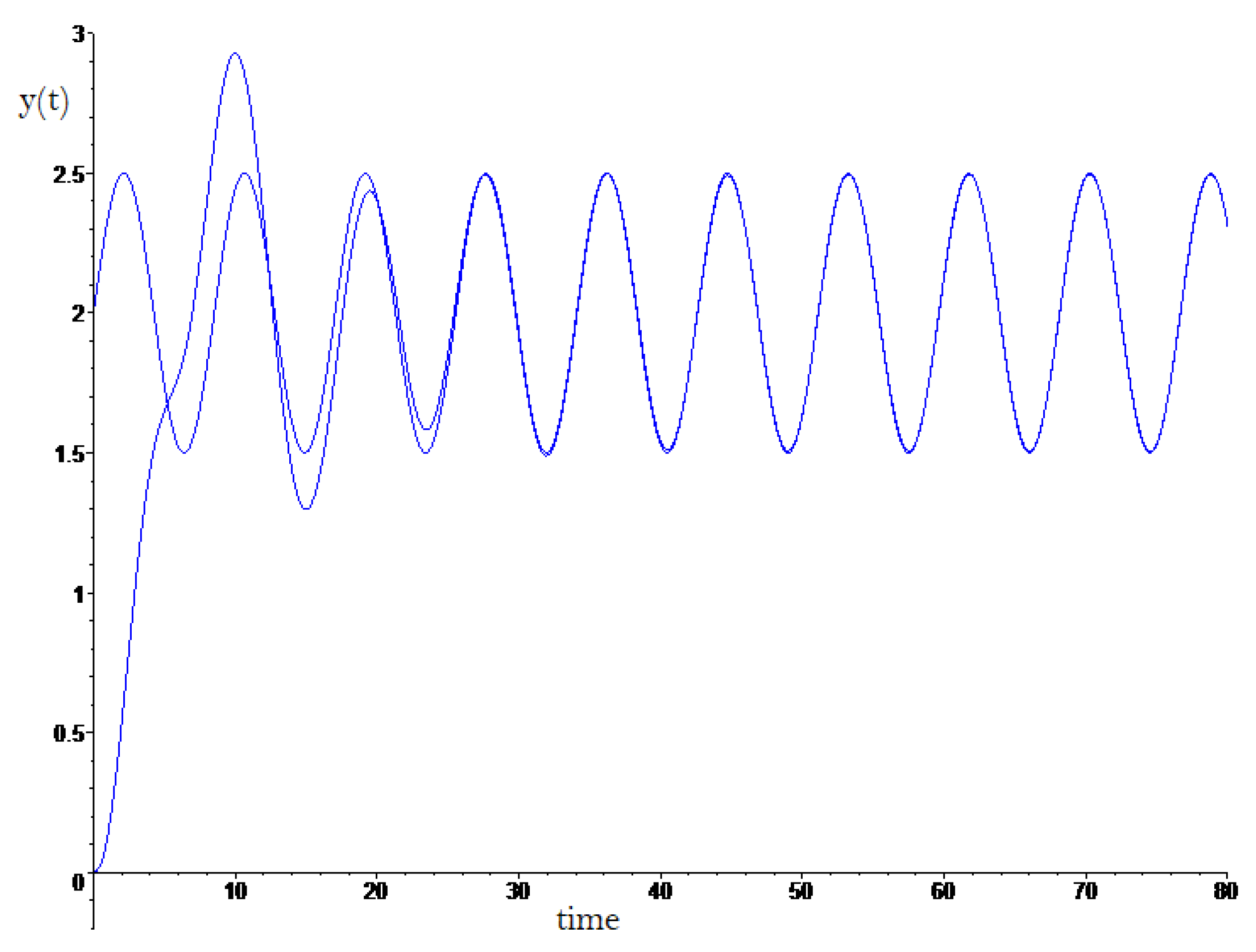
Figure 2 is showed the tracking output voltage
to voltage reference
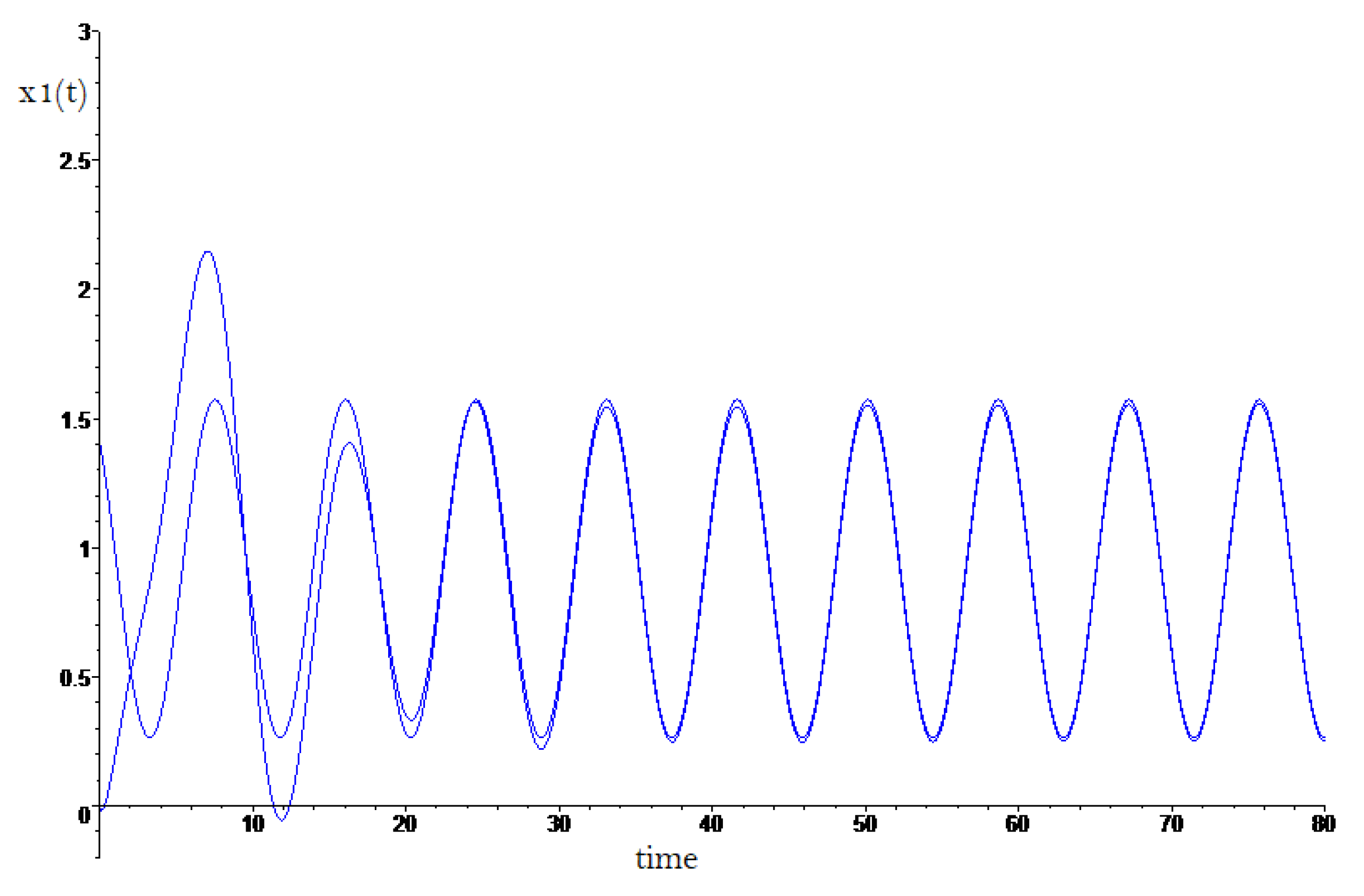
, in the
Figure 3 is showed the current tracking
to reference signal
,
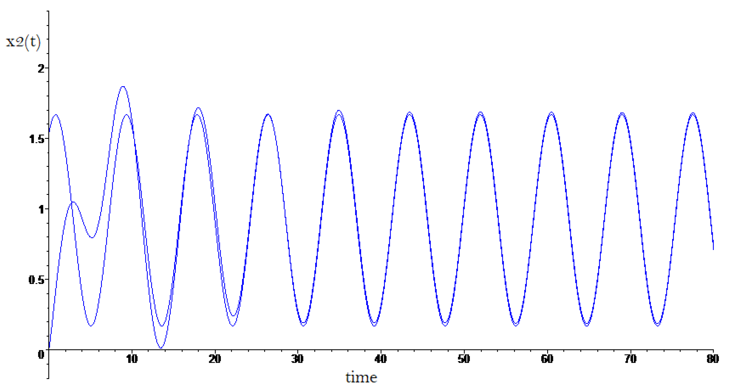
Figure 4 shows the current tracking
to reference signal
.
5. Conclusions
In this note we present a different topology in order to track exactly the output voltage of the DC-to-DC Boost and Buck-Boost power converters to some biased sinusoidal signal. The proposed controller makes use of a nonlinear model to obtain the exact necessary inputs to get zero error tracking between the currents. A future work, with the Dc-to-Dc power converters exposed previously, it is consider the inclusion of another input to the converter with the same objective; the sinusoidal tracking. Another objective is relax certain conditions in order to use less DC energy.
References
- E. Fossas-Colet and J. M. Olm-Miras, "Asymptotic Tracking in DC-To-DC Nonlinear Power Converters", Discrete and Continuous Dynamical Systems Series B, Vol. 2, No. 2, May 2002, pp. 295-307.
- G. Obregón-Pulido, E. G. Obregón-Pulido, E. Nuño, K. Castañeda and A. De-Gyves, "An Adaptive Control to Perform Tracking in Dc to DC Power Converters", Proc. 7th Conference on Electrical Engineering, Computing Science and Automatic Control, Sep 8-10, 2010, pp. 188-191.
- G. Obregón-Pulido, G. G. Obregón-Pulido, G. Sol-s-Perales, J. A. Meda-Campaña, G. A. Vega-Gómez and E. Ruiz-Velázquez, "Energy Considerations for Tracking in DC to DC Power Converters", Mathematical Problems in Engineering, (2019),1098243.
- R. O. Caceres, and I. Barbi, "A boost DC-AC converter:analysis, design and experimentation", IEEE Trans.
- J. M. Olm, X. J. M. Olm, X. Ros and Y. B. Shtessel "A Stable inversion-based robust tracking control in DC-DC nonlinear switched converters", 48th IEEE Conference on Decision and Control and 28 Chinese Control Conference, Dec 2009, pp. 2789-2794.
- E. Fossas, J. M. E. Fossas, J. M. Olm and A.S.I. Zinober, "Robust Tracking Control of DC-to-DC Nonlinear Power Converters", Proc. IEEE Conference on Decision and Control, Dec 2004, pp.5291-5296.
- H. Sira-Ramirez, "Sliding Motions in Bilinear Switched Networks", IEEE Trans. Circ. and Syst., Vol. 34, No. 8, (1987), pp. 919-933.
- A. Sawar et. al. "Generalized State Space Model for a n-Phase Interleaved Buck-Boost Converter" 4th IEEE Utar Pradesh Section International Conference of Electrical, Computer and Electronics (UPCON) GLA University, pp 62-67, 26-28 Oct. 2017.
- G. A. Anaya-Ruiz et. al., "Design and prototyping of transformerless DC-DC converter with high voltage ratio for MVDC applications", IEEE Latin America Transactions, Vol. 21, No. 1, (2023) pp. 62-70.
- S. Hasanpour et. al., "A New High Efficiency High Step-Up DC/DC Converter for Renewable Energy Applications", IEEE Transactions on Industrial Electronics, Vol. 70, No. 2, (2023), pp. 1489 - 1500.
- N. Husna A. W. et. al., "Modeling of DC-DC converter for solar energy system applications", 2012 IEEE Symposium on Computers & Informatics (ISCI), March 2012.
- G. Guru, et. al. G. Guru, et. al. "Dual input superboost DC–DC converter for solar powered electric vehicle", IET Power Electronics, Vol.12, No.9., (2019), pp. 2276-2284.
- H.K. Khalil, Nonlinear Systems, 3rd Edition, Upper Saddlfre River, New Jersey, USA. Prentice Hall, 2002.
|
Disclaimer/Publisher’s Note: The statements, opinions and data contained in all publications are solely those of the individual author(s) and contributor(s) and not of MDPI and/or the editor(s). MDPI and/or the editor(s) disclaim responsibility for any injury to people or property resulting from any ideas, methods, instructions or products referred to in the content. |
© 2023 by the authors. Licensee MDPI, Basel, Switzerland. This article is an open access article distributed under the terms and conditions of the Creative Commons Attribution (CC BY) license (http://creativecommons.org/licenses/by/4.0/).


