Preprint
Article

Effect of Different Standard Geometry Shapes on the Tensile Properties of 3D-Printed Polymer

Altmetrics

Downloads

313

Views

78

Comments

0

A peer-reviewed article of this preprint also exists.

Submitted:

12 June 2023

Posted:

13 June 2023

You are already at the latest version

Alerts
Abstract
The objective of this research is to conduct a comparative analysis between rectangular-shaped ASTM D3039 specimens with different angles (0°, 15°, and 90°) and various tensile test specimens based on ASTM and ISO standards, all 3D-printed using polyethylene terephthalate glycol (PETG) material through FDM. The study aimed to assesses the weak spot commonly found at the neck of the specimens. Two different printing orientations, namely flat and on-edge, were investigated, and a comprehensive examination and comparison were made regarding the variations in tensile strength, E-modulus, strain, and elongation at break among the tested samples. Additionally, the broken areas was evaluated, and a numerical study utilizing the finite element method (FEM) was conducted to identify stress risers' locations in each specimen type. The experimental results demonstrated that the ASTM D3039-0° specimen exhibited the best tensile properties when printed in the on-edge orientation, while the flat orientation yielded the best results in terms of the broken area. On the other hand, the ISO 527-2 specimens displayed the lowest tensile properties, regardless of the printing orientation. The study highlighted the enhanced tensile properties achieved with the rectangular shape. Specifically, the tensile strength of ASTM D3039-0° was 17.87% and 21% higher than that of the ISO 527 geometry shape for the flat and on-edge orientations, respectively. The numerical analysis indicated that the ISO 527-2 specimen had either no or minimal stress raisers, and the higher stresses observed in the narrow section were isolated from the gripping location.
Keywords: 
Subject: Engineering  -   Industrial and Manufacturing Engineering

1. Introduction

A new method of producing components was idealized when the third industrial revolution began to impact the manufacturing and process environment. The first commercial use of additive manufacturing (AM), commonly known as 3D printing, came about in the late 1980s. The earliest machines belonged to the stereolithography family and utilized light-sensitive materials, which solidify when exposed to light. Stratasys developed the fused deposition modelling (FDM) machine in the late 1980s and early 1990s which is considered another fast-prototyping method that gained popularity over the following several years, and it immediately grew to the top of the list of techniques used in academic and research activities [1]. A heated nozzle is used by FDM 3D printers to melt solid thermoplastic filament, which is then deposited layer by layer to create 3D objects. Ultrafine (<100 nm) and fine (<2.5 µm) particles and vapors are produced during the heating and extrusion as a byproduct [2]. Properties and finishing quality are influenced by the chemistry of the materials and the manufacturing process parameters that are used [3],[4].
The impact of processing parameters on dimensional accuracy [5], mechanical properties (such as tensile [6,7], fatigue, and compressive), tribological characteristics [8,9] and surface quality [10] have been reviewed in the literature. Filling percentage [11], Layer height [12], infill pattern [13], build orientation [14], extrusion temperature [15], and contour width (number of perimeters) [16] are some of the most discussed 3D printing process settings. Numerous thermoplastic materials, such as acrylonitrile butadiene styrene (ABS), polylactic acid (PLA), polyethylene terephthalate-glycol (PETG), polyamide, and polyether ether ketone (PEEK), were investigated using these parameters in the form of filaments. One such polymer is polyethylene terephthalate-glycol (PETG), which is used to print the components using the FDM process. It is a saturated thermoplastic polyester created when terephthalic acid and ethylene glycol polycondensation [17]. Compared to different polymer materials, it offers better mechanical, thermal, and strength properties [18].
Tensile strength is the capacity of a substance to resist forces applied under tension. It is important to determine tensile cracking and the final failure of the material since it is a key component of breaking as it is known to greatly impact the mechanical properties of materials. According to Onwubolu [19], layer and raster thickness should be improved in order to increase the tensile strength of ABS polymer. Tensile tests are employed to compare a few different FDM materials [20]. Investigated are even variations in polymer characterization techniques (tensile testing) [21]. The impact of process parameters, including print orientation, raster pattern, and dimensions of tensile specimen on anisotropy has been examined in relation to different tensile test specimen geometries on mechanical properties [22]. Additionally, a common characteristic known as infill patterns affects the behavior of the materials due to an inner substructure [23,24]. The deviation in response associated with this substructure has been studied in polylactic acid (PLA) parts with various infill patterns [25]. The impacts of printing parameters on the toughness and strength resulting in interlocking mechanisms such as raster angle, raster width, and contour width, are also being investigated [23,24,26,27]. Studies have explored the impact of layer thickness, build orientation, and feed rate on 3D-printed PLA samples [28], as well as the effects of raster angle and layer thickness parameters for both PLA and ABS materials [29].
There are two major organizations involved in the field of additive manufacturing (AM), namely ASTM and ISO. ASTM committee F42, established in 2009, aims to advance knowledge, foster research, and promote the adoption of additive manufacturing technologies by developing industry standards. On the other hand, the ISO technical committee ISO/TC 261, operating since 2011, is dedicated to standardizing various aspects of additive manufacturing. This includes processes, terminology, definitions, process chains (both hardware and software), testing procedures, quality parameters, supply agreements, and foundational concepts [30]. Both ASTM and ISO are actively involved in the development of standards for mechanical testing of additive manufacturing (AM) materials and components. In their efforts, they are evaluating the suitability of existing standards for conducting mechanical tests on polymer-based AM materials and parts. The standards are categorized into two groups: one for plastics, which include ASTM D638 [31], and ISO 527-2 [32], and the other for composites, which include ASTM D3039 [31] and ISO 527-4 [33,34]. Apart from the standard recommendations, practical considerations can also influence the decision to conduct customized tests instead of relying solely on standardized ones, including the selection of specimen type. These choices may be driven by specific practical needs [35]. For example, the utilization of non-standard specimens, particularly subsize ones, may be necessary when the availability of feedstock material is limited, particularly in cases where new formulations are being investigated for research purposes. Additionally, for costly materials, smaller samples than the prescribed size may be preferred due to the destructive nature of tensile testing [35].
Due to the absence of specific international standards, the evaluation of tensile properties in FDM parts often relies on dumbbell-shaped specimens, commonly referred to as "dog-bones," which are based on ASTM D638 [36]. Similar to ASTM D638, ISO 527-2 [32] also specifies the use of dumbbell-shaped specimens. These standards define the geometry of the specimens, which is determined by the thickness of the sample or the type of composite being tested. Tensile tests conducted on these specimens provide information on Young's modulus, strength, Poisson's ratio, yield stress, and elongation to break [37,38,39]. However, despite the widespread use of dumbbell-shaped specimens based on ASTM D638 and ISO 527-2, it is often observed that failure occurs outside the intended narrow section. This is primarily due to the challenges associated with reproducing the dog bone geometry through FDM printing [37,39,40,41,42,43]. The original purpose of the ample fillet in the narrow section was to reduce stress concentration in specimens with changing cross-sectional areas, such as those shaped or manufactured from continuous solids like sheets or plates. However, reproducing the curvature of this fillet using FDM printing poses difficulties. Consequently, structural defects can arise, such as abrupt raster terminations, material gaps (particularly in contoured parts), or sudden changes in the deposition path. These factors can lead to abnormal stress peaks and non-axial stress states at the radii, especially in relatively thin specimens [39,44,45,46].
ISO 527-2 and ASTM D638 (determining the tensile characteristics for extrusion and molding plastics) have been used to evaluate the materials' response, where the researchers [24,44,47] discovered that specimens prematurely failed this early failure was due to the stress concentration in the dog bone's radius close to the gauge length. The end of the filaments in this section of the specimens created an extreme shear. To overcome the challenges associated with FDM printing, an alternative approach involves modifying the original dog-bone geometry by increasing the curvature radius [37,39,48]. As a potential solution, ASTM D3039 has been proposed [44,49,50]. This standard is primarily designed for evaluating the tensile properties of polymer-matrix composite materials. However, it can also be applied to neat polymer parts printed using FDM due to their similarity to orthotropic laminae. Miller et al. [43] examined the tensile behavior of ABS samples printed using fused filament fabrication (FFF). Rectangular coupons adhering to ASTM D3039 exhibited a higher percentage of samples meeting the acceptable failure standard compared to ASTM D638 type I and type IV dog-bone specimens. Type IV dog-bones showed better compliance with the failure criterion than type I. The fillet radius was identified as the primary factor causing inconsistent failure in ASTM D638 dog bones, while the inclusion of an additional inner radius improved the performance of type IV specimens. ASTM D638 type IV overestimated the elastic modulus, whereas ASTM D3039 overestimated the elastic modulus but underestimated the tensile strength. ASTM D638 type I performed equally well as ASTM D638 type IV and ASTM D3039 for the elastic modulus and strength [43]. To sum up, tensile standards were not particularly investigated for AM technologies, but they have been discovered and listed as presented in Table 1.
Even though it is not always possible to optimize the parameters for every design and polymeric system, learning more about the geometry shapes properties relationship of additively-manufactured geometries could help researchers create better parts for future applications. Although specimen shape and size play a critical role, their influence on the obtained data has not been extensively studied. This knowledge gap is significant since the irregularity of the data hinders the ability to make reliable comparisons both within the provided information and across technical reports. In this study, the test specimen shape and grasping were investigated to determine the tensile performance. It is necessary to understand the effect of changing the selected design of tensile geometry shape and printing parameters on the tensile properties of the FDM test specimens. Therefore, the present study forms part of an investigation into exploring the design freedom of 3D printing. The variables selected for this experiment were chosen based on the experience and knowledge of the researchers. Five different geometry shape specimens’ configurations have been prepared, (ISO 527, three types of ASTM D3039, and ASTM D638) of PETG polymer. The specimens have been produced in 3D printing with two different building orientations (flat, and on-edge) by using the FDM technique to examine the effects of using different orientations on the tensile strength and elongation at the break. Moreover, computational simulations using the finite element method (FEM) have been employed to compare different specimen geometries. The influence of various geometry shapes and building orientation on the tensile properties of 3D-printed PETG has rarely been studied before. This research is an area for which there is limited information published about how to apply these different geometry shapes to the tensile properties of PETG.

2. Materials and Methods

2.1. Manufacturing of 3D-Printed Specimens

The tensile test samples were fabricated on a commercial 3D printing machine “Geetech A20M” of FDM type. The working area of the printer is 255 x 255 x 255 mm, which has allowed production of several parts at the same time. To gain a thorough understanding of the mechanical characteristics, the material's processing parameters could be varied while producing the specimens on the FDM printer. Changes in process parameters were applied to the CAD design, which was generated by the CAD program "Solidworks 2021" and exported as stl file, using the slicing software Ultimaker Cura 5.2.1. The parameters performed while printing the specimens are described in Table 2.
Polyethylene terephthalate glycol (PETG) has been used for the manufacturing of specimens. The PETG filament is a black color branded Filanora and having a diameter of 1.75 mm. The Mechanical properties of PETG filament are listed in Table 3.
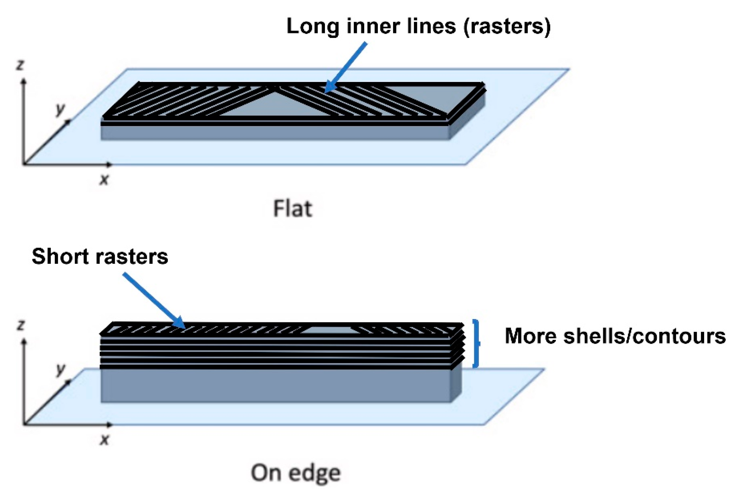
The standards used for manufacturing the targeted specimens and the dimensions and other specifications of each specimen’s type are mentioned in Table 4. Figure 1 illustrates all specimen designs created by using SolidWorks software. All these tensile standard-shape specimens created were printed in two build orientations (flat and on edge) to determine the effect of print orientation on the mechanical properties as well. Figure 2 illustrates the specimen design orientations used for the production of the tensile testing samples.

2.2. Experimental

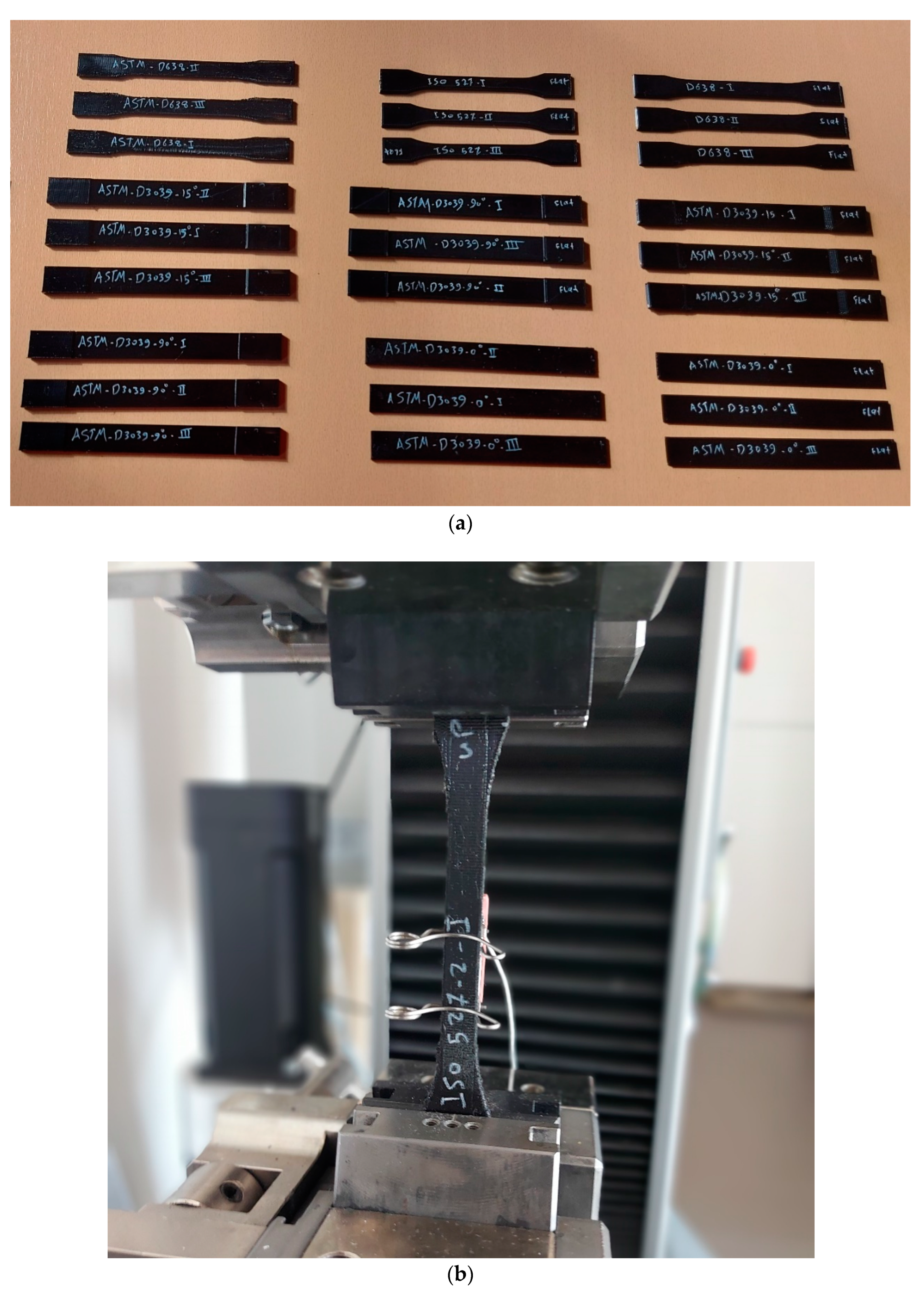
The experiments in this study were made to assess the influence of tensile test specimens' geometry on the mechanical characteristics and mode of failure. The Zwick/Roell Z100, a universal testing device, was used to test specimens for tensile strength. There have been ten different sets of specimens were prepared (coming from five cases of standards with two build orientations), as shown in Figure 3a. As mentioned in section 2.1, the specimen dimensions were according to the ASTM D638, ASTM D3039 (0°, 15°, and 90°), and ISO 527-2 for tensile testing of PETG polymer. Three identical specimens (printed with the same print settings) from each set were tested under similar conditions. Figure 3a shows groups of tensile test samples according to different geometry shapes (standards). The tensile behavior determination included the tensile strength, tensile Young's modulus, and the failure form under the specified conditions. The modulus of elasticity determined experimentally within the elastic range by using an extensometer in order to study the strain rate sensitivity (viscoelasticity) (see Figure 3b). Extensometer, which is attached to tensile test specimens while testing, is an instrument for measuring elongation and helps calculate Young's modulus precisely. Also, from the extensometer measurements, the mechanical properties could be obtained are; nominal strain at tensile strength (Ꜫtm), stress at break (σB), strain at break (ꜪB), and nominal strain at break (ꜪtB). Each specimen is fixed by the grips as it is seen in Figure 3b. The specimens were stretched at a steady speed of 3 mm/min along with their longitudinal axis until they broke.

2.3. Modeling of tensile tests by using finite element method

A series of numerical simulations were performed using the finite element method (FEM) to have a more detailed vision of the effect of specimens’ geometries on the mechanical properties. The commercial software ANSYS 17.2 was used in these simulations.

2.3.1. Modeling

The numerical simulation is an approximation method, where the governing equations are being integrated on every element forming the so-called numerical model. For structural analysis, the so-called weak form was being recovered and applied according to equation 1.
Ω   σ i j δ u i j d V = Ω   t ^ j δ u i d A
This equation is applied to every finite element (Ω) with its closure ( ) as the boundary, and the underlying continuum body's shape. The material was treated as an isotropic material with constant properties in all directions. The isoperimetric Galerkin method [52,53] selects the test function ( δ u i ) from the same Hilbertian Sobolev space as the displacement field ( u i ). The system was simplified, and the linear strain measure was utilized because the deformation on a tensile test is minimal. The strain and stress could be calculated using equations (2) and (3), respectively.
ε i j = 1 2 u i j + u j i
Hooke's law can be applied because of the observed elasticity without rate effects,
σ i j = C i j k l ε k l
where the stiffness tensor of rank four ( C i j k l ), the stress tensor ( σ i j ), and the strain tensor ( ε i j ), are linearly connected.

2.3.2. Meshing and Boundary Conditions

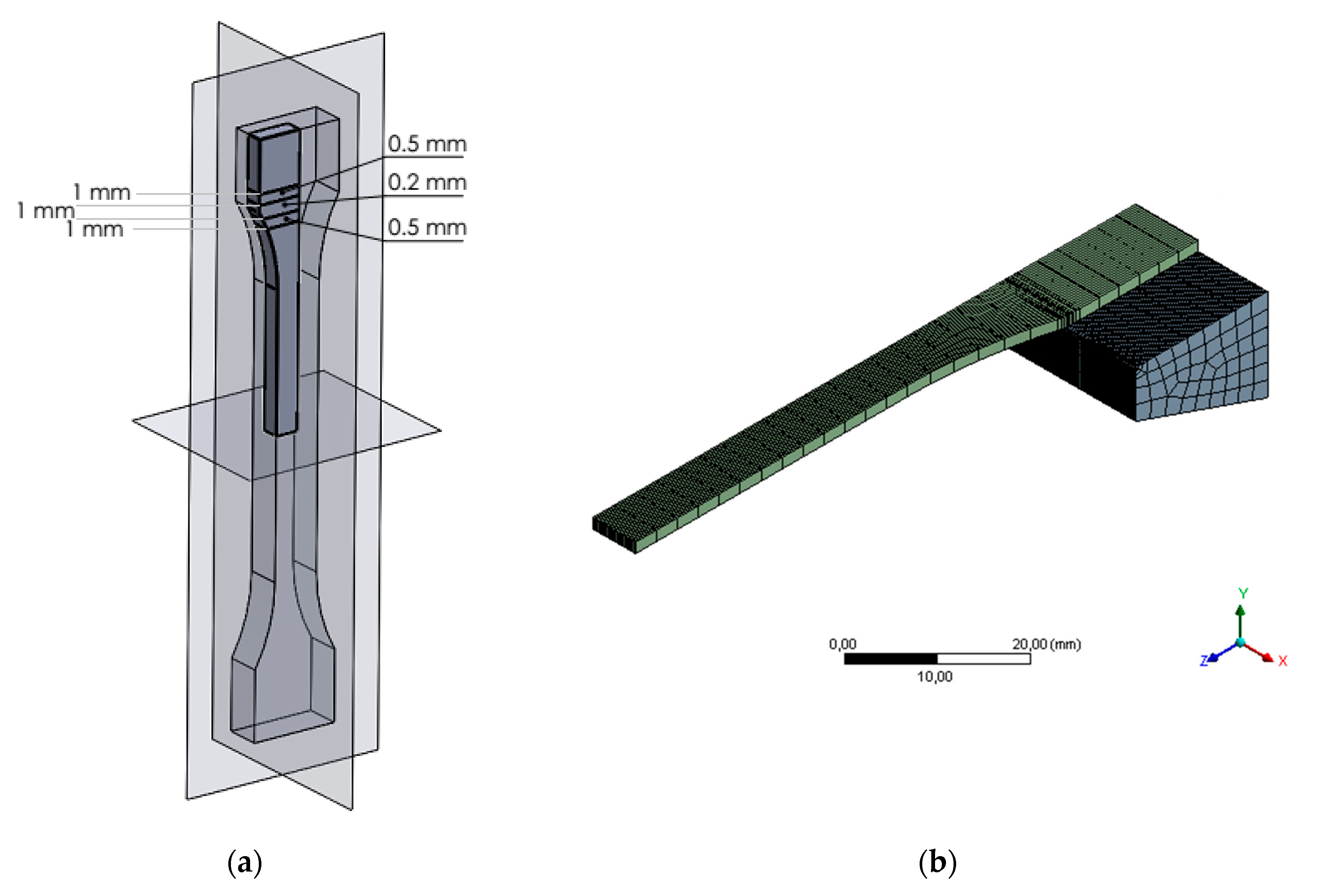
In every numerical simulation, the numerical mesh plays a key role in obtaining valid results. In order to benefit the geometrical symmetry and reducing the computational cost every specimen’s geometrical model was clipped using its symmetry plans, resulting in only one eight of the original geometry and half of the gripping mechanism from the experimental apparatus. Furthermore, a uniform element size was used except for the regions with high changing rates in cross-section areas, as shown in Figure 4.
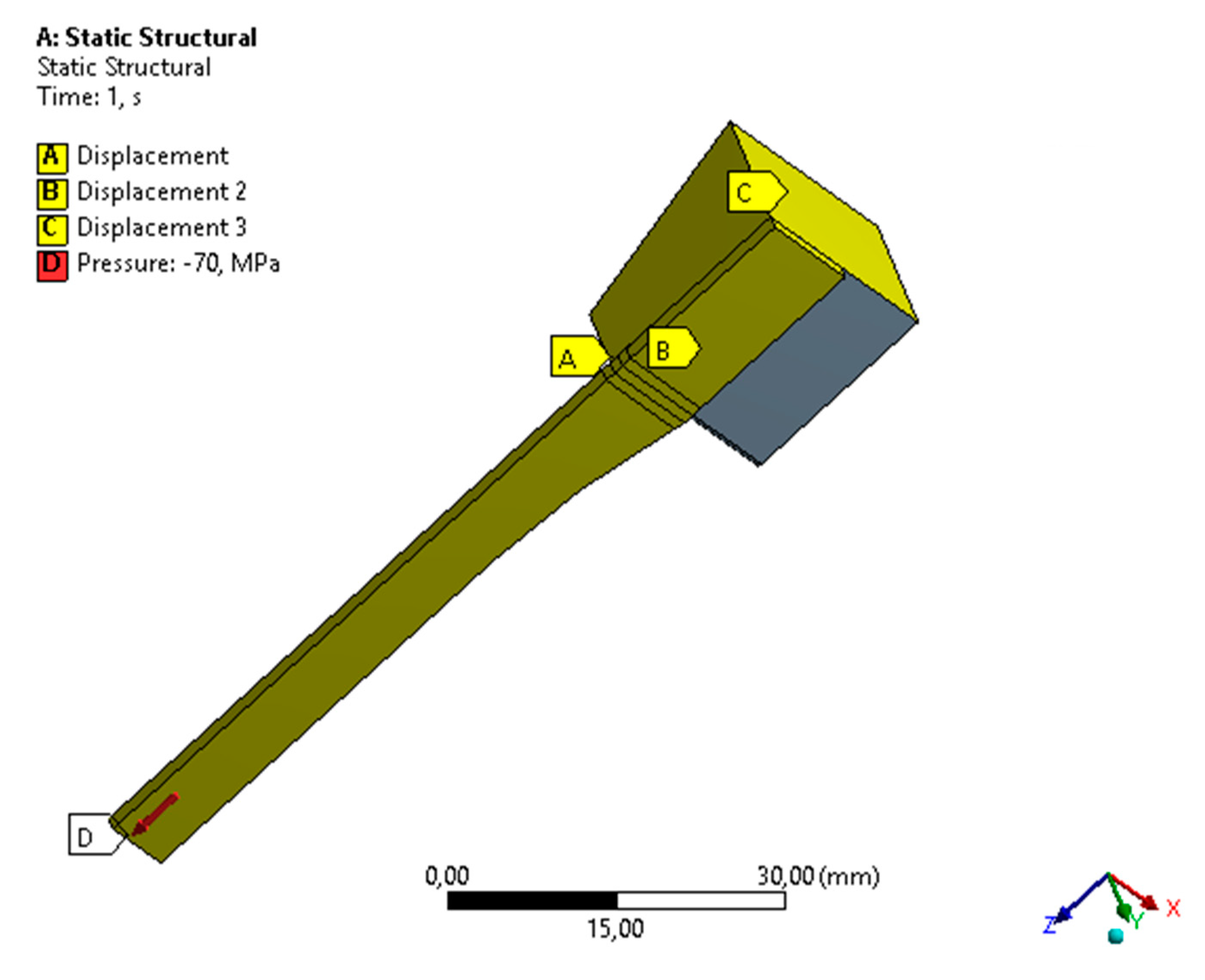
As for the boundary conditions, to emphasize the true geometrical effect and to exclude the effect of different (Force vs. Elongation) curves, a uniform stress of 70 MPa was applied to every numerical study with a frictional contact between the specimen and the gripping jaw alongside with a zero displacement of the gripping jaw as shown in Figure 5.

3. Results and Discussion

3.1. Experimental Results

Various variables, as discussed in the literature, can effectively increase stiffness and strength. The major variables that influence deformations and deflections include material properties, layer binding, and FDM 3D printing parameters (mainly, infill pattern and build orientation). To delve deeper into the characteristics of build orientations, it is helpful to look at the structure of printed tensile test specimens in Figure 2. Every layer has inner lines and a shell (contour). The direction of the layer contour for the flat sample is parallel to the applied tensile test force. These specimens exhibited a higher likelihood of elongation due to the presence of long internal lines constructed at a 45° angle and a sufficient number of layers, resulting in increased strain. The on-edge workpiece possesses a complex structure characterized by a cross-section with numerous layers, a narrow contour, and short internal lines. This explains how these samples were pulled with a great degree of strength during the test.
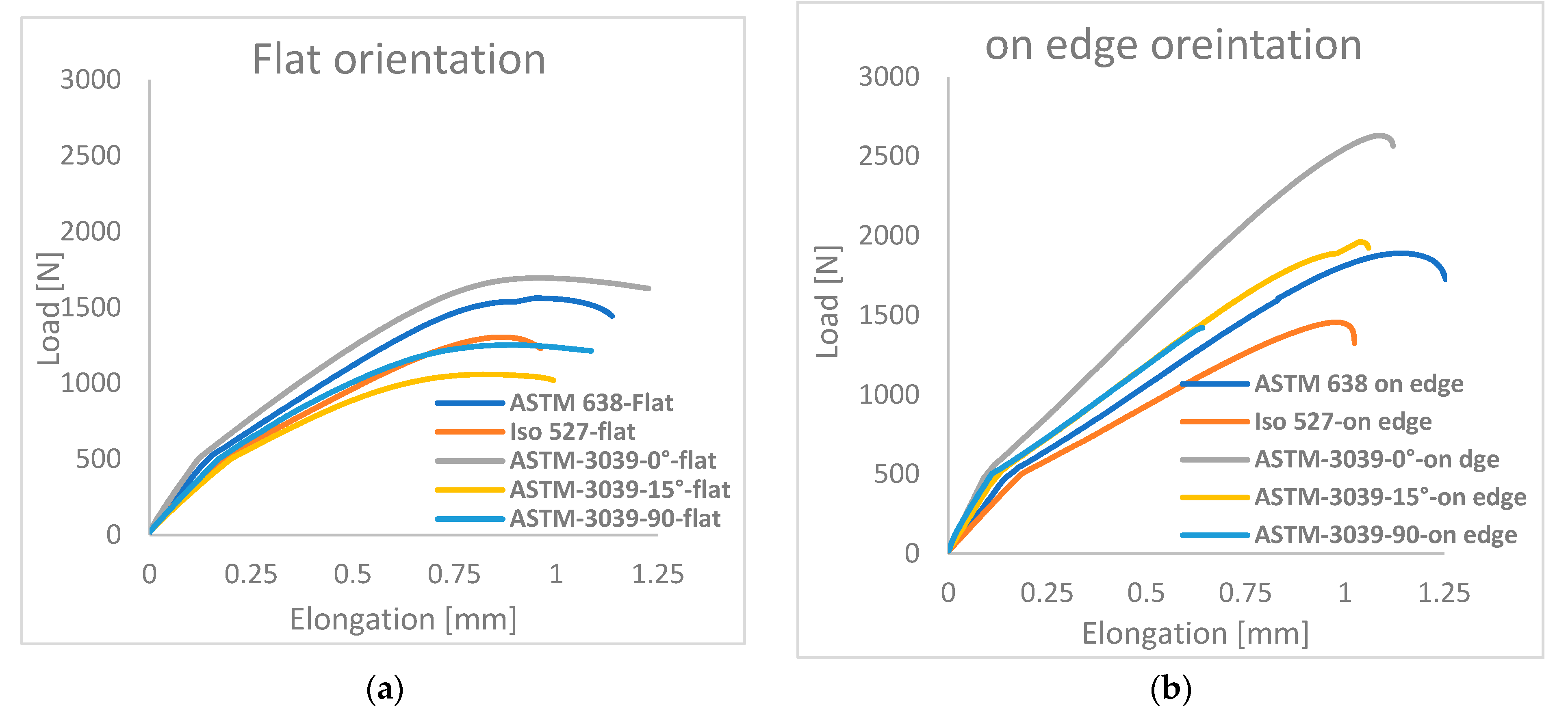
The load-displacement curves that were obtained from the tensile test for all examined shape geometry and orientations are shown in Figure 6. It is clear that the building orientation of the 3D printing parameter and the shape geometry has a significant impact on the values of force versus elongation. The results were divided into two diagrams according to the building orientations and the shapes of tensile standards examined. The highest applied loads required to reach the fracture, for the different shape geometry, were reported to the ASTM D3039-0° (for both flat and on edge), as shown in Figure 6. The average values (out of three testing results for each orientation) of these highest loads obtained were 1693 N and 2632 N for flat and on edge orientation, respectively. Comparably, ASTM D638 standard specimens also showed a relatively high load ranging between 1562 N and 1890 N for flat and on-edge orientation, respectively. In contrast, the lowest loads were reported in specimens of the ASTM D3039-15° (at the flat build orientation) and ISO 527 (at the on-edge build orientation) with the values 1026 N and 1475 N, consecutively.
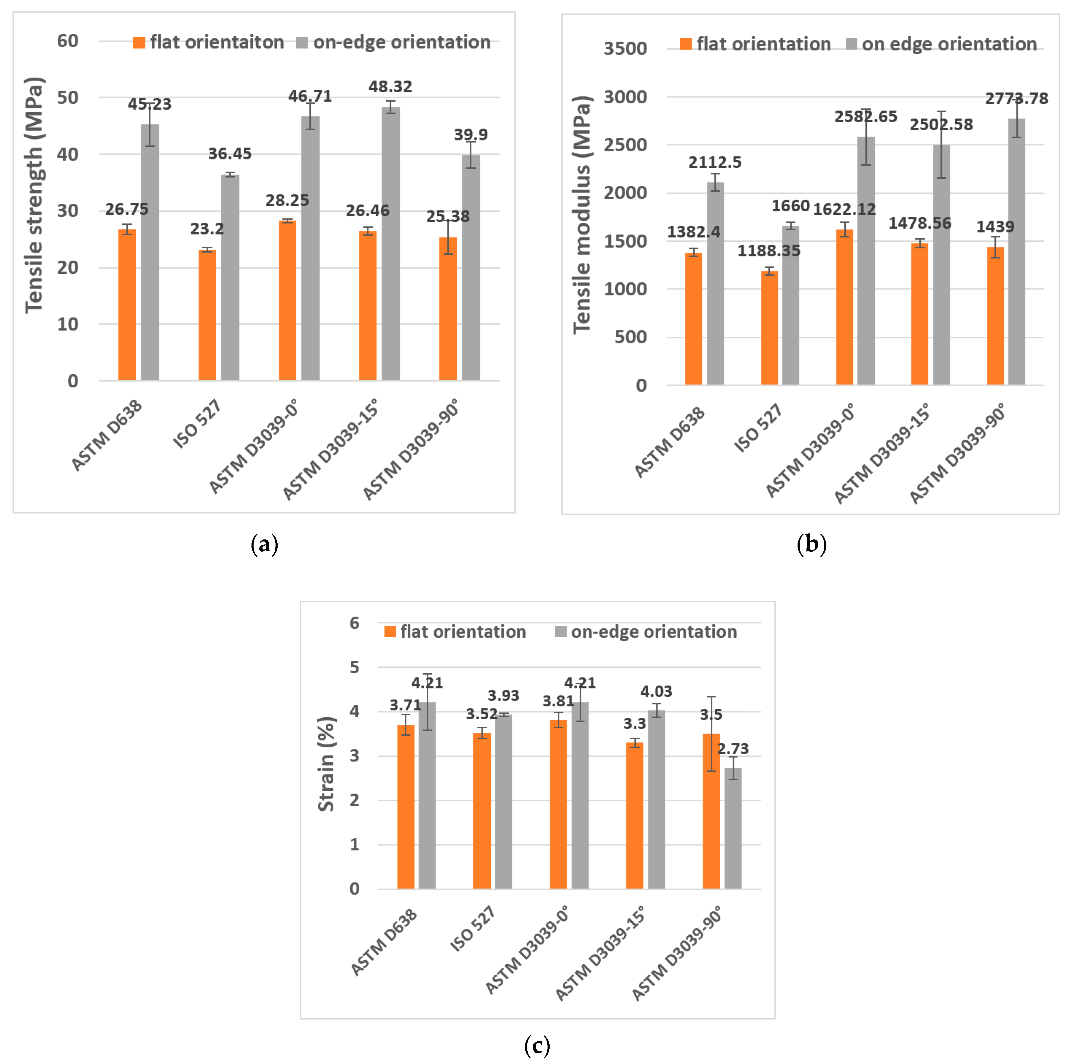
Figure 7(a-c) presents the results of the ultimate tensile strength, tensile modulus, and tensile strain of the tested specimens. In terms of the tensile strength, it can be seen from Figure 7a that at flat build orientation samples, the values ranged between 23.2 MPa and 28.25 MPa, where the best strength was for ASTM D3039-0°. However, the on-edge build orientation showed higher tensile strength ranged between 36.45 and 48.32 MPa, and the better values were from ASTM D3039-15°. In both flat and on-edge orientations, the lowest tensile strengths were to the ISO 527specimens. The increased tensile strength of these specimens is due to their reliable geometry shape which avoided the weak spot at the neck (curvature) of the specimens of ASTM D638 and ISO 527. Therefore, the applied load was distributed across a larger area, resulting in higher resistance to failure. Regarding the effect of print orientation, generally, the on-edge specimens revealed much higher tensile strength as compared to the flat-printed ones. For instance, the average of the ASTM D3039-0° tensile strength for on-edge orientation was 39.52% higher than that of the flat orientation. Furthermore, the increased tensile strength of ASTM D3039-0° for flat and on-edge orientations was higher than the ISO 527 geometry shape (the weakest) by 17.87% and 21%, respectively. In comparison between ISO 527 and ASTM D638, the tensile strength average of ASTM D638 specimens was higher than the average of ISO 527 specimens by 13.27% and 19.5% for flat and on edge orientation, respectively.
In terms of the tensile modulus, the flat build orientation values were ranged between 1188 MPa and 1622 MPa, where the best values were from ASTM 3039-0°. On the other hand, the tensile modulus of the on-edge build orientation ranged between 1660 MPa and 2773 MPa, and the better values were from ASTM D3039-90° (see Figure 7b). In addition, the tensile modulus of ASTM D3039-0° was 26.74% and 40.15% higher than the ISO 527 geometry shape (the lowest modulus) for the flat and on-edge orientations, respectively. In comparative between ASTM D638 and ISO 527, the average of ASTM D638 specimens was 14% and 21% higher than the ISO 527 geometry shape for flat and on-edge orientations, consecutively. Concerning the tensile strain (see Figure 7c), its values were ranged between 2.73% and 4.21% (for both orientations), where the best values were to the ASTM D3039-0° and ASTM D638 together, while the lowest value was to the ISO 527. The tensile strain average value of the ASTM 3039-0° at on-edge orientation was 9.5% higher than the flat orientation of the same shape.
The average value of other tensile test mechanical properties (i.e., Ꜫtm (nominal strain at tensile strength), σb (stress at break), Ꜫb (strain at break), and Ꜫtb (nominal strain at break)) of each geometry shape are tabulated in Table 5.
By testing FDM dog bone shape specimens, Kay [54] credited the lower tensile strengths and a higher degree of disassembling to the use of ASTM D638, which is not recommended (according to him). The researcher highlighted how failures frequently happened in the neck area of dog bones manufactured with FDM as a result of stress concentration in the part's transition zones. Nevertheless, notable enhancements were observed when conducting tests on parts in accordance with ASTM D3039. It is important to note that ASTM D638 is primarily intended for testing conventional polymeric bulk materials, while the additive manufacturing parts in question more closely resemble composite structures [54]. Conversely, ASTM D3039 is specifically tailored for evaluating composite materials based on their geometry. Consequently, it is anticipated that these parts would exhibit higher values for ultimate tensile strength and modulus due to a greater proportion of continuous polymer extruded fibers spanning the length of the gauge section.
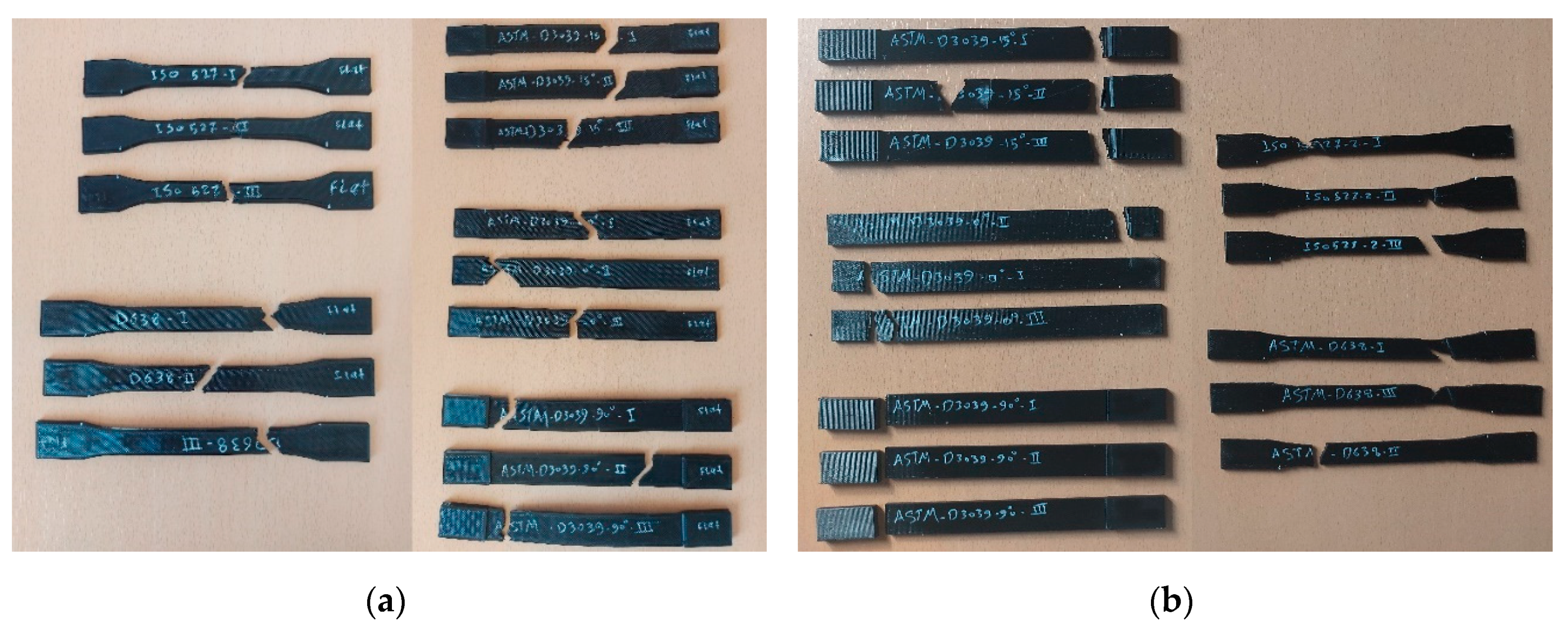
Figure 8 shows the broken specimens after the tensile test. As it is well known, the breakage/failure is much better to be in the middle of the gauge section than other parts of specimen. Obviously from Figure 8, the broken area for the on-edge orientation was always near the edge of the specimen; the breaks near the gripping area, which is not recommend. In general, the on-edge orientation of FDM samples tends to yield higher strength, as indicated by the findings from various standards investigated. However, the impact of orientation is particularly notable when considering the ASTM D638 and ISO 527 standards. These observations align with the results reported by Aliheidari et al. [55], supporting the notion that the mechanical properties are directly influenced by the distinctive characteristics of the layered structure, specifically the adhesion between the layers.
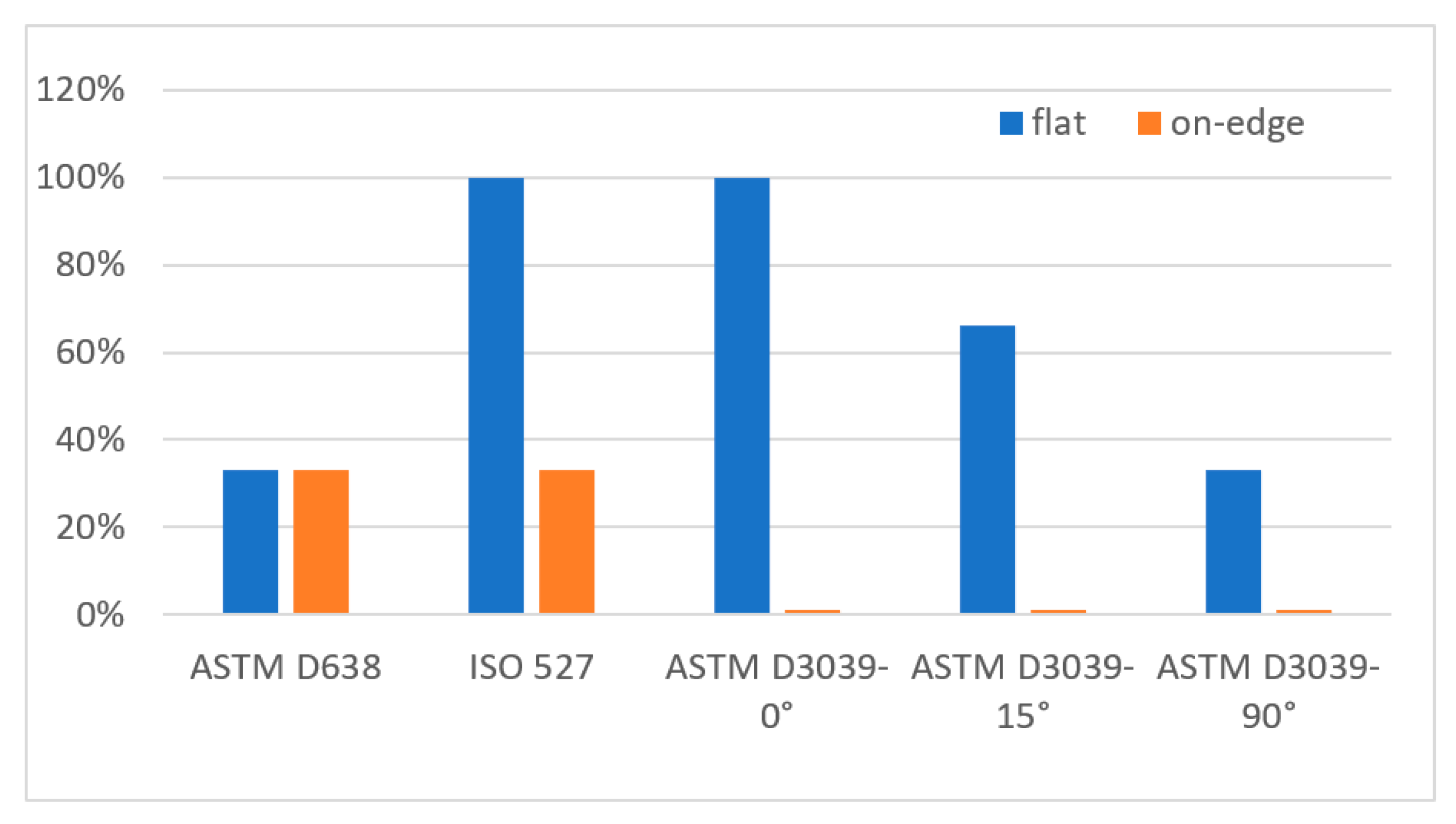
In contrast, the fracture in most of flat printed specimens was almost in the middle. To distinguish in which geometry shape and printing parameter the specimen’s failure was better, the broken area was given a percentage out of 100% (called the good breakage area) considering the fracture place from the middle of the sample; the closer to the middle the higher the percentage, and vice versa. Therefore, if the broken area is near the neck/edge, then it is not considered to get the good fracture. Figure 9 shows the percentage of the good breakage area based on the specimens’ fractures depicted in Figure 8.

3.2. Numerical Results

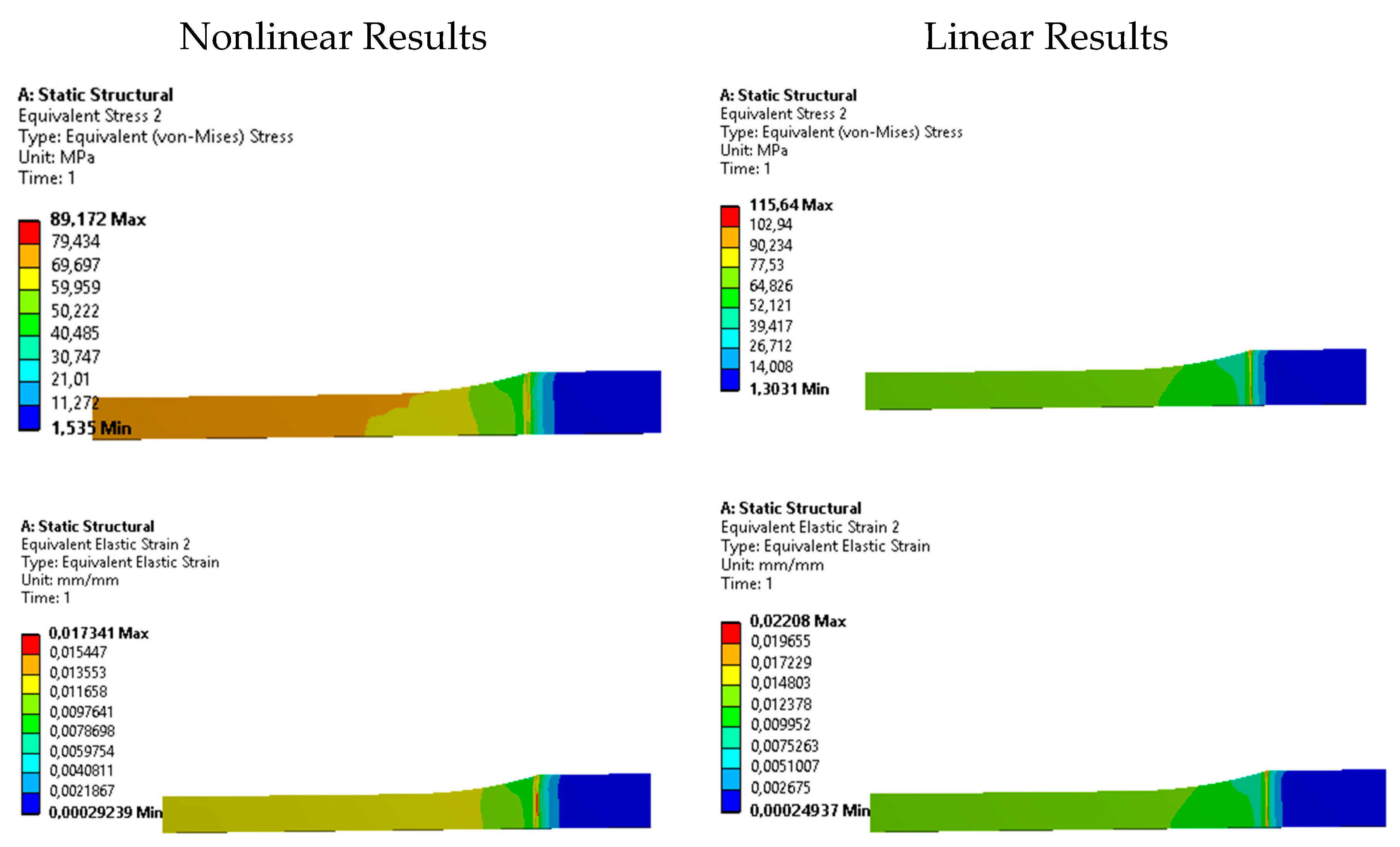
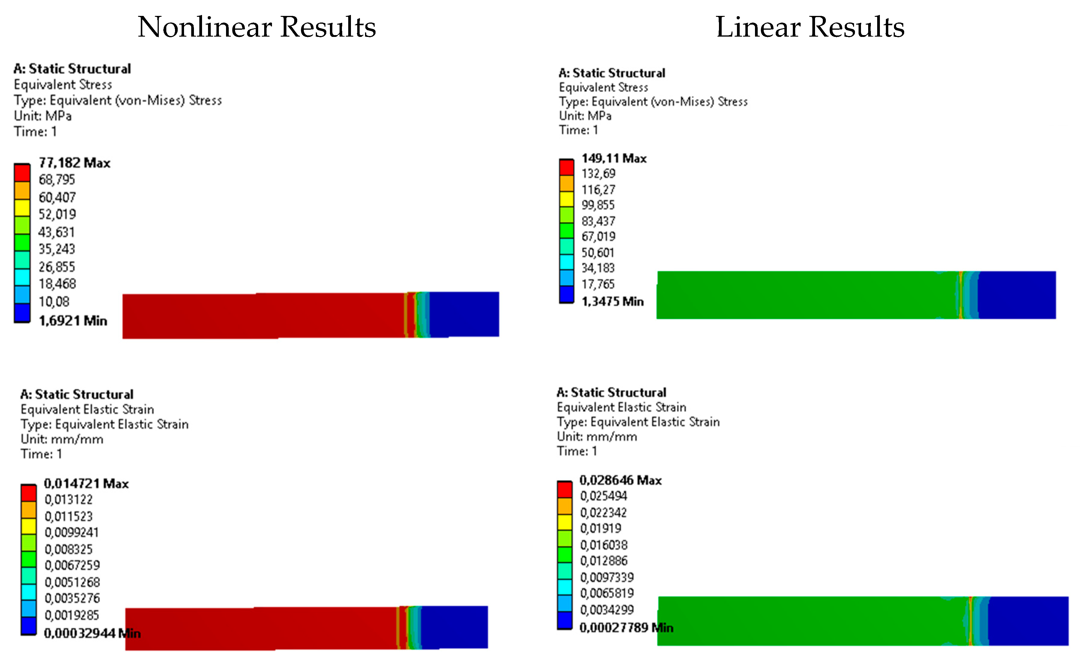
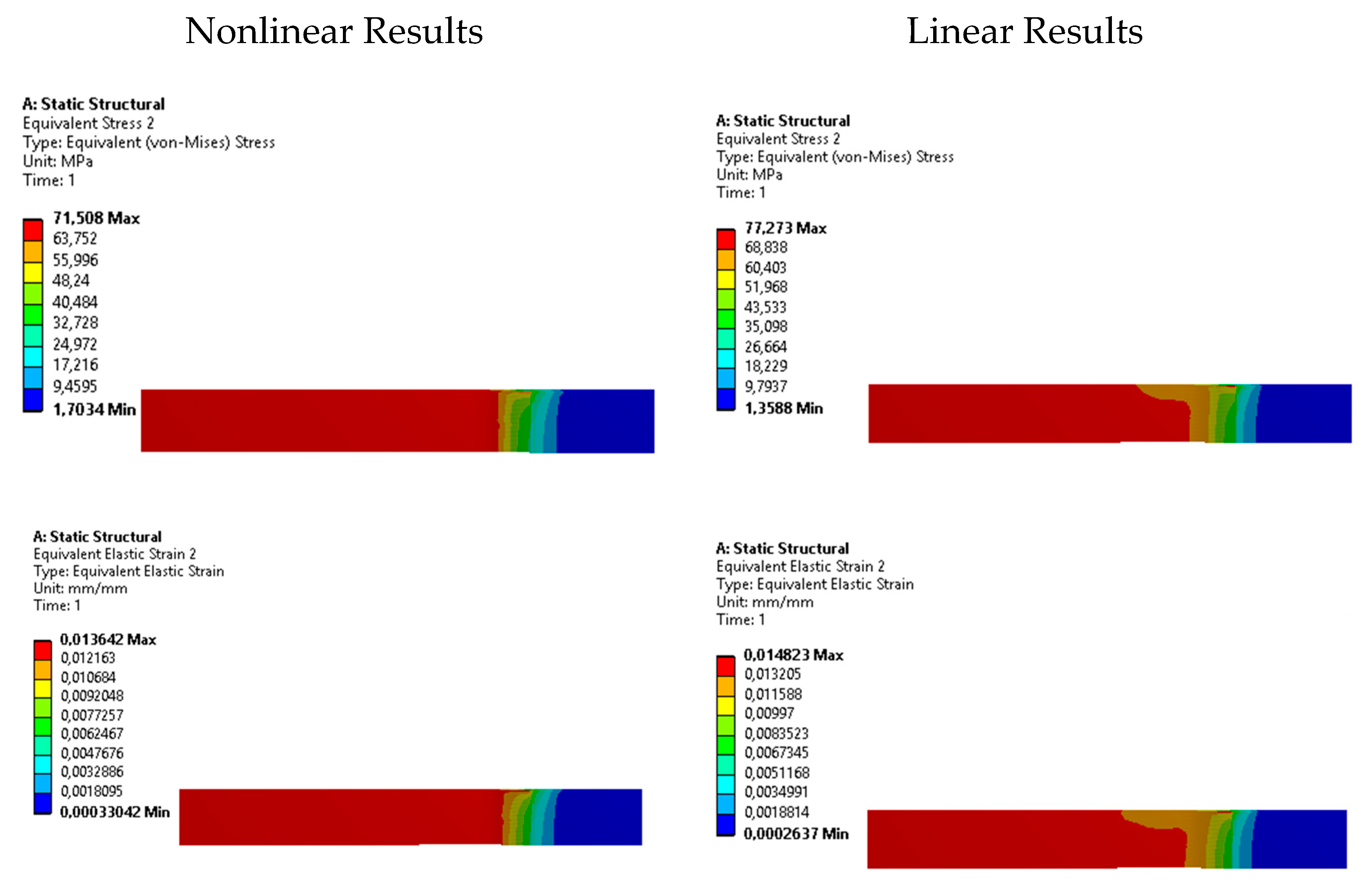
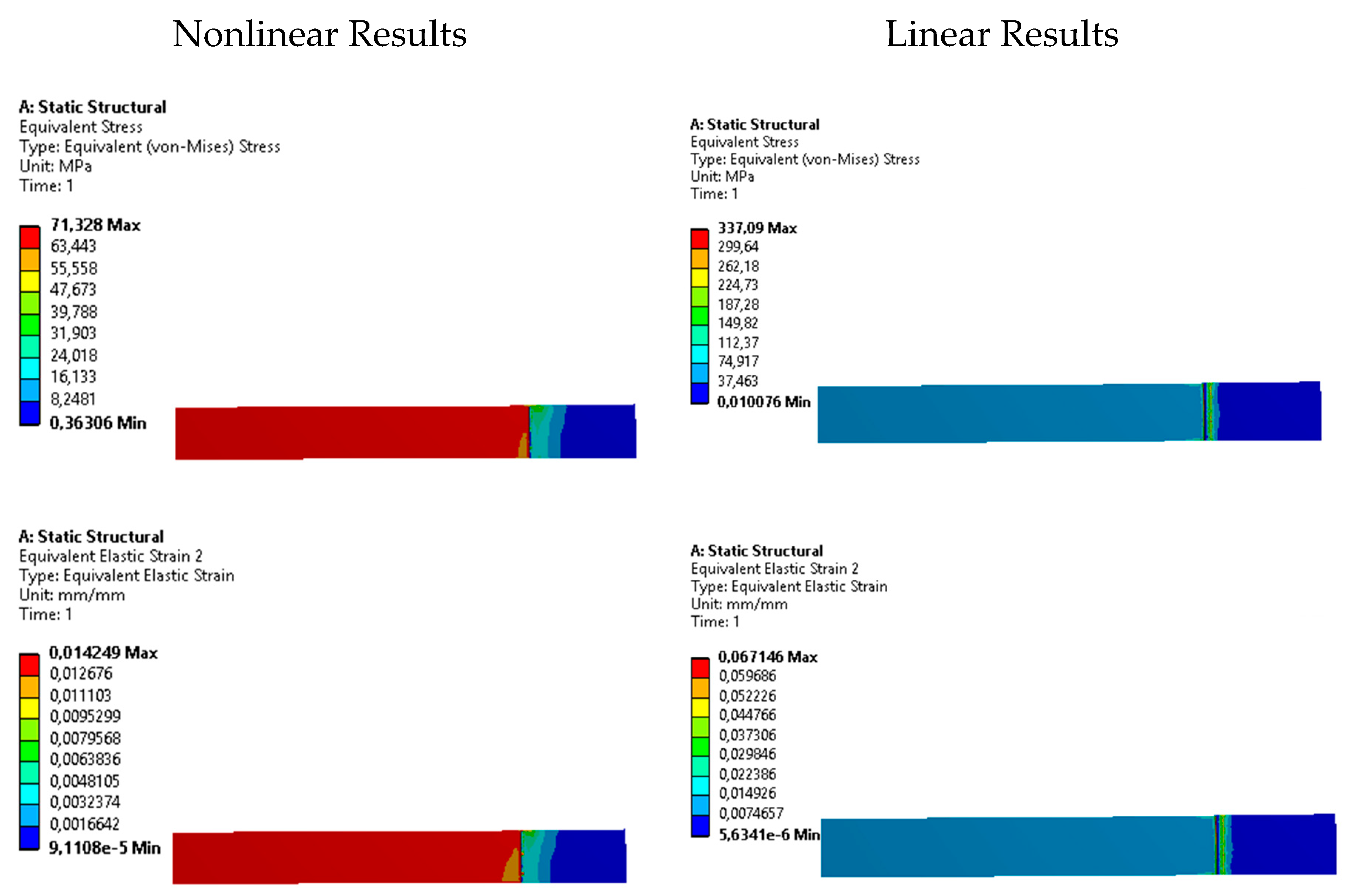
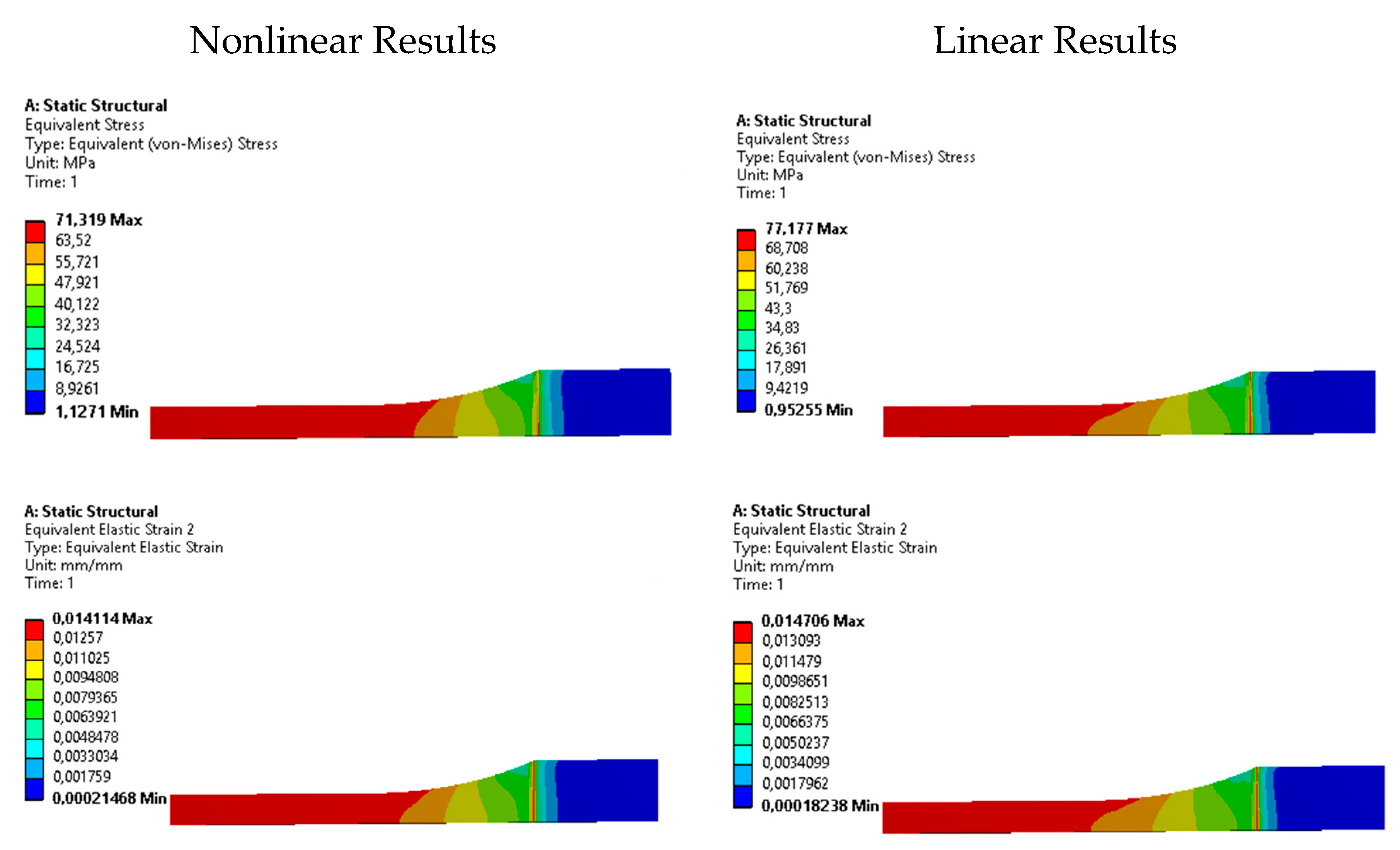
In structural analysis, the material’s stress – strain curve can be expressed in two different methods, linear and nonlinear curves. In the linear analysis, the material’s stress – strain curve is assumed to be a linear curve, while using the nonlinear method requires implementing a digital form of the true material stress – strain curve. In this research, both methods were used to evaluate the ability of linear models to capture the physical phenomena correctly. Young's modulus was considered 5250 MPa in case of linear and nonlinear modelling. Additional properties of nonlinear modelling are Yield strength of 70 MPa and Tangent modulus 10 MPa. Table 6 presents the maximum Von – Mises stress for every specimen with its shape-specific stress-increasing effect since the stress of 70 MPa was used in the boundary conditions.
From the results in Figure 6, it can be clearly observed that the linear stress – stain model multiplier factor, the equivalent stress while the nonlinear model, gives closer values to the value used in the simulation settings. To further investigate the effect of geometrical shape on stress and strain distribution, contour plots of equivalent Von – Mises stress and strain were generated to emphasize the local stress riser’s locations. Figure 10, Figure 11, Figure 12, Figure 13 and Figure 14 show these plots for specimens’ type ASTM D638, ASTM D3030-0°, ASTM D3039-15°, ASTM D3039-90°, and ISO 527-2, respectively. Stress and strain plots show stress risers located in the transition area from the gripping location to the middle narrow area, especially in the specimens ASTM D638 and ASTM D3039 (see Figure 10, Figure 11, Figure 12 and Figure 13). However, the specimen shape ISO 527 – 2, Figure 14, has no or little stress risers at the gripping area, and the maximum stresses concentrate in the narrow/gauge section, as it should. This conclusion suggests that the specimen type ISO 527–2 is more stable when tested in materials’ mechanical studies since it is barely affected by the fixture and clamping mechanism as compared to the other specimens.

4. Conclusions

The effect of standard specimens’ geometry shape, manufactured using FDM technology, on the mechanical characterization of polymers has been achieved in this study. For uniaxial tensile studies, five various geometries were studied with different building orientations (flat and on-edge) for PETG material. Also, a comparison of specimens’ geometries was studied numerically using the finite element method in order to determine stress risers’ locations in every specimen. Based on the results obtained, the following observations can be drawn.
The preferred specimen geometries for tensile testing of FDM parts are typically in the form of dumbbell and rectangular shapes, as indicated by current standards. However, there is a lack of consensus regarding the superior geometry choice between these two options. Based on available data, it is suggested that rectangular samples with straight edges, such as those conforming to ASTM D3039, offer more favorable mechanical characteristics compared to dumbbell-shaped samples with curved edges, as seen in ASTM D638. Experimental results demonstrate that the use of the ASTM D3039 rectangle shape, supported by straight edges, reduces the occurrence of abrupt transition zones and early failures caused by stress concentration. Conflicting results for different geometry shapes may arise due to various factors, including the type of feedstock material employed (amorphous vs. semi-crystalline, pure polymer vs. composite material, etc.), printer configuration and printing parameters, as well as the specific test procedures utilized.
Regarding the effect of print orientation, the best tensile properties were for the on-edge building orientation specimens (39.4% higher than the flat) due to their robust inner structure.
The numerical results showed that the specimen type ASTM D638 had a huge stress concentration in the transition in cross section area near the gripping location. That was repeated in the ASTM D3039 in a similar manner. Nevertheless, the specimen type ISO 527-2 had no or little stress raisers near the gripping area while the higher stresses located in the narrow/gauge section isolating the stresses from the clamping location.
In conclusion, the majority of current standards are appropriate for testing parts made using additive manufacturing (AM). However, additional advice is needed to handle the engineering properties measurements made using AM techniques. Methodologies to evaluate the performance of novel materials and their suitability for particular platforms must be standardized as 3D printing progresses from a tool for prototyping to a mass-production manufacturing technique.

Author Contributions

Conceptualization, R.F.F. and Z.Sz.; methodology, R.F.F., M.M.H. and Z.Sz.; software, I.O.; validation, R.F.F., M.M.H. and A.H.; formal analysis, R.F.F. and Z.Sz.; investigation, R.F.F., M.M.H.; resources, Z.Sz. and I.O.; data curation, R.F.F., M.M.H.; writing—original draft preparation, R.F.F., V.V. and A.H.; writing—review and editing, M.M.H., and I.O.; visualization, R.F.F. and Z.Sz.; supervision, Z.Sz. and I.O.; project administration R.F.F.; funding acquisition, Z.Sz. All authors have read and agreed to the published version of the manuscript.

Funding

This research received no external funding.

Data Availability Statement

The data used to support this study’s findings can be provided by the corresponding author upon reasonable request.

Acknowledgments

This work was supported by the Stipendium Hungaricum Programme and by the Mechanical Engineering Doctoral School, Szent István Campus, MATE University, Gödöllő, Hungary.

Conflicts of Interest

The authors declare no conflict of interest.

References

  1. Wohlers, T.; Gornet, T. History of Additive Manufacturing. Wohlers Rep. 2014, 24, 118. [Google Scholar] [CrossRef]
  2. Zukas, V.; Zukas, J.A. An Introduction to 3D Printing; First Edition Design Pub., 2015; ISBN 1-62287-897-3. [Google Scholar]
  3. Auhl, D.; Rohnstock, F.; Löschke, O.; Schäfer, K.; Wang, P.; Wagner, M.H. 3D-Printing Quality in Relation to Melt Flow and Fusion Behavior of Polymer Materials.; Zlín, Czech Republic, 2019; p. 030004.
  4. Thompson, M.K.; Moroni, G.; Vaneker, T.; Fadel, G.; Campbell, R.I.; Gibson, I.; Bernard, A.; Schulz, J.; Graf, P.; Ahuja, B.; et al. Design for Additive Manufacturing: Trends, Opportunities, Considerations, and Constraints. CIRP Ann. 2016, 65, 737–760. [Google Scholar] [CrossRef]
  5. Hanon, M.M.; Zsidai, L.; Ma, Q. Accuracy Investigation of 3D Printed PLA with Various Process Parameters and Different Colors. Mater. Today Proc. 2021, 42, 3089–3096. [Google Scholar] [CrossRef]
  6. Hanon, M.M.; Dobos, J.; Zsidai, L. The Influence of 3D Printing Process Parameters on the Mechanical Performance of PLA Polymer and Its Correlation with Hardness. Procedia Manuf. 2021, 54, 244–249. [Google Scholar] [CrossRef]
  7. Hanon, M.M.; Ghaly, A.; Zsidai, L.; Szakál, Z.; Szabó, I.; Kátai, L. Investigations of the Mechanical Properties of DLP 3D Printed Graphene/Resin Composites. Acta Polytech. Hung. 2021, 18, 143–161. [Google Scholar] [CrossRef]
  8. Hanon, M.M.; Ghaly, A.; Zsidai, L.; Klébert, S. Tribological Characteristics of Digital Light Processing (DLP) 3D Printed Graphene/Resin Composite: Influence of Graphene Presence and Process Settings. Mater. Des. 2022, 218, 110718. [Google Scholar] [CrossRef]
  9. Hanon, M.M.; Zsidai, L. Comprehending the Role of Process Parameters and Filament Color on the Structure and Tribological Performance of 3D Printed PLA. J. Mater. Res. Technol. 2021, 15, 647–660. [Google Scholar] [CrossRef]
  10. Hanon, M.M.; Zsidai, L. Sliding Surface Structure Comparison of 3D Printed Polymers Using FDM and DLP Technologies. In Proceedings of the IOP Conference Series: Materials Science and Engineering; IOP Publishing, 2020; Vol. 749, p. 012015. [Google Scholar]
  11. Fernandez-Vicente, M.; Calle, W.; Ferrandiz, S.; Conejero, A. Effect of Infill Parameters on Tensile Mechanical Behavior in Desktop 3D Printing. 3D Print. Addit. Manuf. 2016, 3, 183–192. [Google Scholar] [CrossRef]
  12. Ayrilmis, N.; Kariz, M.; Šernek, M.; Kuzman, M.K. Effects of Sandwich Core Structure and Infill Rate on Mechanical Properties of 3D-Printed Wood/PLA Composites. Int. J. Adv. Manuf. Technol. 2021, 115, 3233–3242. [Google Scholar] [CrossRef]
  13. Akhoundi, B.; Behravesh, A.H. Effect of Filling Pattern on the Tensile and Flexural Mechanical Properties of FDM 3D Printed Products. Exp. Mech. 2019, 59, 883–897. [Google Scholar] [CrossRef]
  14. Rybachuk, M.; Mauger, C.A.; Fiedler, T.; Öchsner, A. Anisotropic Mechanical Properties of Fused Deposition Modeled Parts Fabricated by Using Acrylonitrile Butadiene Styrene Polymer. J. Polym. Eng. 2017, 37, 699–706. [Google Scholar] [CrossRef]
  15. Guessasma, S.; Belhabib, S.; Nouri, H. Understanding the Microstructural Role of Bio-Sourced 3D Printed Structures on the Tensile Performance. Polym. Test. 2019, 77, 105924. [Google Scholar] [CrossRef]
  16. Lanzotti, A.; Grasso, M.; Staiano, G.; Martorelli, M. The Impact of Process Parameters on Mechanical Properties of Parts Fabricated in PLA with an Open-Source 3-D Printer. Rapid Prototyp. J. 2015. [Google Scholar] [CrossRef]
  17. Dupaix, R.B.; Boyce, M.C. Finite Strain Behavior of Poly (Ethylene Terephthalate)(PET) and Poly (Ethylene Terephthalate)-Glycol (PETG). Polymer 2005, 46, 4827–4838. [Google Scholar] [CrossRef]
  18. Guo, J.; Xiao, R.; Tian, C.; Jiang, M. Optimizing Physical Aging in Poly(Ethylene Terephthalate)-Glycol (PETG). J. Non-Cryst. Solids 2018, 502, 15–21. [Google Scholar] [CrossRef]
  19. Onwubolu, G.C.; Rayegani, F. Characterization and Optimization of Mechanical Properties of ABS Parts Manufactured by the Fused Deposition Modelling Process. Int. J. Manuf. Eng. 2014, 2014. [Google Scholar] [CrossRef]
  20. Paper – RTe Journal Available online:. Available online: https://rtejournal.de/paper (accessed on 19 August 2022).
  21. Pereira, T.; Potgieter, J.; Kennedy, J.V. A Fundamental Study of 3D Printing Testing Methods for the Development of New Quality Management Strategies. In Proceedings of the 2017 24th International Conference on Mechatronics and Machine Vision in Practice (M2VIP); IEEE; 2017; pp. 1–6. [Google Scholar]
  22. Torrado, A.R.; Roberson, D.A. Failure Analysis and Anisotropy Evaluation of 3D-Printed Tensile Test Specimens of Different Geometries and Print Raster Patterns. J. Fail. Anal. Prev. 2016, 16, 154–164. [Google Scholar] [CrossRef]
  23. Shojib Hossain, M.; Espalin, D.; Ramos, J.; Perez, M.; Wicker, R. Improved Mechanical Properties of Fused Deposition Modeling-Manufactured Parts Through Build Parameter Modifications. J. Manuf. Sci. Eng. 2014, 136, 061002. [Google Scholar] [CrossRef]
  24. Tymrak, B.M.; Kreiger, M.; Pearce, J.M. Mechanical Properties of Components Fabricated with Open-Source 3-D Printers under Realistic Environmental Conditions. Mater. Des. 2014, 58, 242–246. [Google Scholar] [CrossRef]
  25. Lubombo, C.; Huneault, M.A. Effect of Infill Patterns on the Mechanical Performance of Lightweight 3D-Printed Cellular PLA Parts. Mater. Today Commun. 2018, 17, 214–228. [Google Scholar] [CrossRef]
  26. Kiendl, J.; Gao, C. Controlling Toughness and Strength of FDM 3D-Printed PLA Components through the Raster Layup. Compos. Part B Eng. 2020, 180, 107562. [Google Scholar] [CrossRef]
  27. Gao, C.; Kiendl, J. Short Review on Architectured Materials with Topological Interlocking Mechanisms. Mater. Des. Process. Commun. 2019, 1, e31. [Google Scholar] [CrossRef]
  28. Chacón, J.M.; Caminero, M.A.; García-Plaza, E.; Núñez, P.J. Additive Manufacturing of PLA Structures Using Fused Deposition Modelling: Effect of Process Parameters on Mechanical Properties and Their Optimal Selection. Mater. Des. 2017, 124, 143–157. [Google Scholar] [CrossRef]
  29. Torrado Perez, A.R.; Roberson, D.A.; Wicker, R.B. Fracture Surface Analysis of 3D-Printed Tensile Specimens of Novel ABS-Based Materials. J. Fail. Anal. Prev. 2014, 14, 343–353. [Google Scholar] [CrossRef]
  30. About Available online:. Available online: https://committee.iso.org/home/tc261 (accessed on 18 August 2022).
  31. ASTM International - Standards Worldwide Available online:. Available online: https://www.astm.org/ (accessed on 18 August 2022).
  32. ISO - ISO 527-1:2012 - Plastics — Determination of Tensile Properties — Part 1: General Principles Available online:. Available online: https://www.iso.org/standard/56045.html (accessed on 18 August 2022).
  33. ISO, E. 527-4. Plastics-Determination of Tensile Properties-Part 4: Test Conditions for Isotropic and Orthotropic Fibre-Reinforced Plastic Composites. Int. Organ. Stand. ISO Geneva Switz. 1997. [Google Scholar]
  34. ISO, B. 527-5. Plastics-Determination of Tensile Properties-Part 5: Test Conditions for Unidirectional Fibre-Reinforced Plastic Composites. Eur. Comm. Stand. 2009. [Google Scholar]
  35. Moura, L.S.; Vittoria, G.D.; Gabriel, A.H.; Fonseca, E.B.; Gabriel, L.P.; Webster, T.J.; Lopes, É.S. A Highly Accurate Methodology for the Prediction and Correlation of Mechanical Properties Based on the Slimness Ratio of Additively Manufactured Tensile Test Specimens. J. Mater. Sci. 2020, 55, 9578–9596. [Google Scholar] [CrossRef]
  36. ASTM ASTM D638-14: Standard Test Method for Tensile Properties of Plastics.; ASTM, 2014.
  37. Auffray, L.; Gouge, P.-A.; Hattali, L. Design of Experiment Analysis on Tensile Properties of PLA Samples Produced by Fused Filament Fabrication. Int. J. Adv. Manuf. Technol. 2022, 1–15. [Google Scholar] [CrossRef]
  38. Shanmugam, V.; Rajendran, D.J.J.; Babu, K.; Rajendran, S.; Veerasimman, A.; Marimuthu, U.; Singh, S.; Das, O.; Neisiany, R.E.; Hedenqvist, M.S. The Mechanical Testing and Performance Analysis of Polymer-Fibre Composites Prepared through the Additive Manufacturing. Polym. Test. 2021, 93, 106925. [Google Scholar] [CrossRef]
  39. Özen, A.; Auhl, D.; Völlmecke, C.; Kiendl, J.; Abali, B.E. Optimization of Manufacturing Parameters and Tensile Specimen Geometry for Fused Deposition Modeling (FDM) 3D-Printed PETG. Materials 2021, 14, 2556. [Google Scholar] [CrossRef]
  40. Tymrak, B.M.; Kreiger, M.; Pearce, J.M. Mechanical Properties of Components Fabricated with Open-Source 3-D Printers under Realistic Environmental Conditions. Mater. Des. 2014, 58, 242–246. [Google Scholar] [CrossRef]
  41. Alvarez, K.; Lagos, R.F.C.; Aizpun, M. Investigating the Influence of Infill Percentage on the Mechanical Properties of Fused Deposition Modelled ABS Parts. Ing e Investig 2016, 36, 110–116. [Google Scholar] [CrossRef]
  42. Chandran, V.; Kalman, J.; Fayazbakhsh, K.; Bougherara, H. A Comparative Study of the Tensile Properties of Compression Molded and 3D Printed PLA Specimens in Dry and Water Saturated Conditions. J. Mech. Sci. Technol. 2021, 35, 1977–1985. [Google Scholar] [CrossRef]
  43. Miller, A.; Brown, C.; Warner, G. Guidance on the Use of Existing ASTM Polymer Testing Standards for ABS Parts Fabricated Using FFF. Smart Sustain. Manuf. Syst. 2019, 3, 20190051. [Google Scholar] [CrossRef]
  44. Ahn, S.-H.; Montero, M.; Odell, D.; Roundy, S.; Wright, P.K. Anisotropic Material Properties of Fused Deposition Modeling ABS. Rapid Prototyp. J. 2002. [Google Scholar] [CrossRef]
  45. Montero, M.; Roundy, S.; Odell, D.; Ahn, S.-H.; Wright, P.K. Material Characterization of Fused Deposition Modeling (FDM) ABS by Designed Experiments. Soc. Manuf. Eng. 2001, 10, 1–21. [Google Scholar]
  46. Rankouhi, B.; Javadpour, S.; Delfanian, F.; Letcher, T. Failure Analysis and Mechanical Characterization of 3D Printed ABS with Respect to Layer Thickness and Orientation. J. Fail. Anal. Prev. 2016, 16, 467–481. [Google Scholar] [CrossRef]
  47. Milosevic, M.; Stoof, D.; Pickering, K. Characterizing the Mechanical Properties of Fused Deposition Modelling Natural Fiber Recycled Polypropylene Composites. J. Compos. Sci. 2017, 1, 7. [Google Scholar] [CrossRef]
  48. Croccolo, D.; De Agostinis, M.; Olmi, G. Experimental Characterization and Analytical Modelling of the Mechanical Behaviour of Fused Deposition Processed Parts Made of ABS-M30. Comput. Mater. Sci. 2013, 79, 506–518. [Google Scholar] [CrossRef]
  49. Somireddy, M.; Czekanski, A. Mechanical Characterization of Additively Manufactured Parts by FE Modeling of Mesostructure. J. Manuf. Mater. Process. 2017, 1, 18. [Google Scholar] [CrossRef]
  50. International, A. Standard Test Method for Tensile Properties of Polymer Matrix Composite Materials; ASTM international, 2007.
  51. Filanora Filatech PETG Filament 1.75mm Black HUF 8,650. Available online: https://www.filanora.eu/filanora-filatech-petg-filament-175mm-fekete?utm_source=olcsobbat&utm_medium=shopping&utm_campaign=olcsobbat_shopping_filanora&gclid=Cj0KCQjwwtWgBhDhARIsAEMcxeB2-8DAuOUQ4xIqctKTWh2ijJtplMVpQLji2zbUy-eEHXh-HLDIqi0aApejEALw_wcB (accessed on 18 March 2023).
  52. Zohdi, T.I. Zohdi; Ditzinger Finite Element Primer for Beginners; Springer, 2018; ISBN 3-319-70427-3. [Google Scholar]
  53. Zienkiewicz, O.C.; Taylor, R.L. The Finite Element Method for Solid and Structural Mechanics; Elsevier, 2005; ISBN 0-08-045558-1. [Google Scholar]
  54. Kay, R. Effect of Raster Orientation on the Structural Properties of Components Fabricated by Fused Deposition Modeling, The Ohio State University, 2014.
  55. Aliheidari, N.; Tripuraneni, R.; Ameli, A.; Nadimpalli, S. Fracture Resistance Measurement of Fused Deposition Modeling 3D Printed Polymers. Polym. Test. 2017, 60, 94–101. [Google Scholar] [CrossRef]
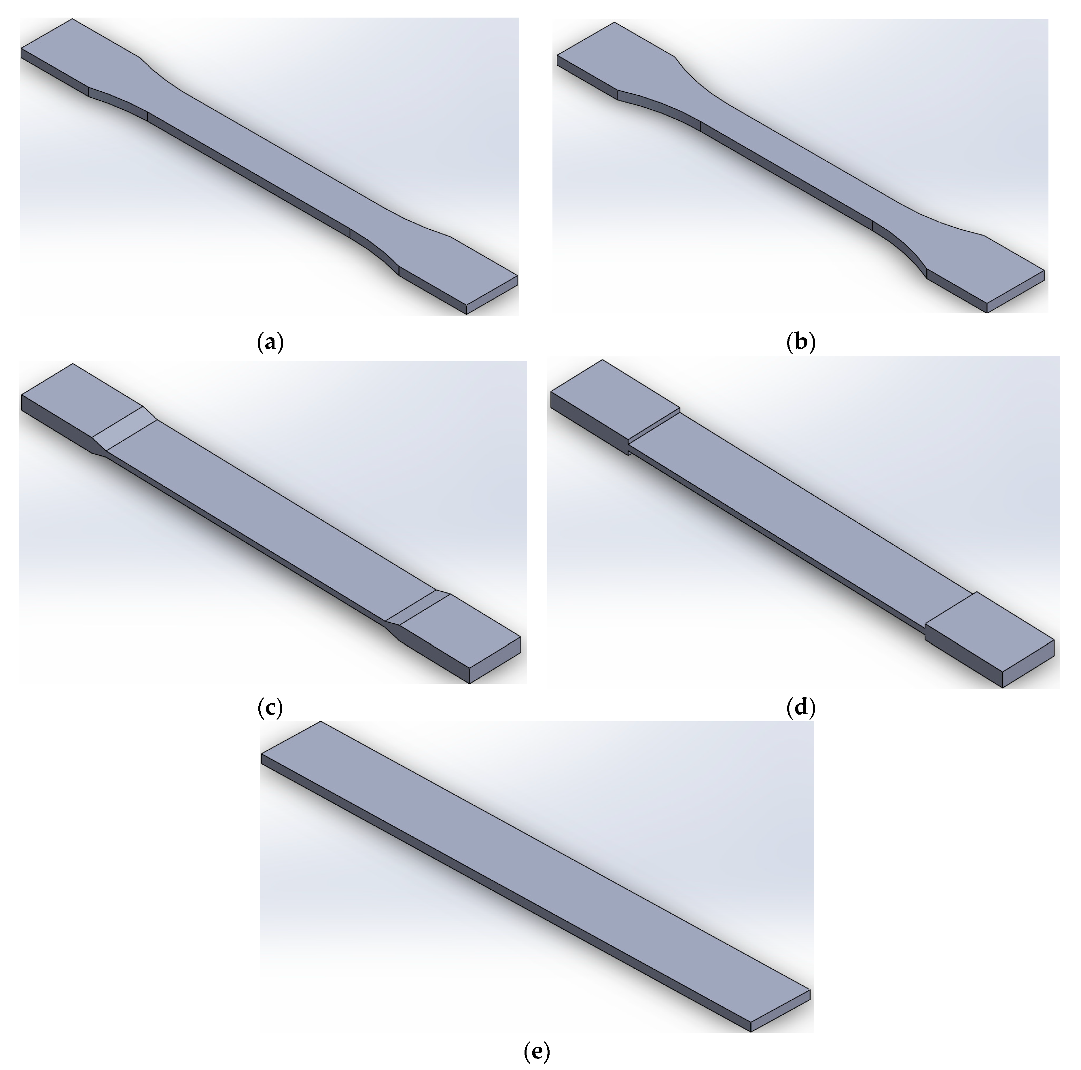
Figure 1. Different geometry shapes of tensile test specimen drawn by SolidWorks software according to the standard (a) ASTM D638, (b) ISO 527-2, (c) ASTM D3039-15°, (d) ASTM D3039-90°, and (e) ASTM D3039-0°.
Preprints 76420 g001
Figure 2. Build orientations examined (flat and on-edge).
Preprints 76420 g002
Figure 3. Tensile testing (a) sets of tensile specimens of different geometries, and (b) extensometer attached to the specimen during tensile testing.
Preprints 76420 g003
Figure 4. Symmetry planes and mesh sizing.
Preprints 76420 g004
Figure 5. Boundary conditions employed in the simulation.
Preprints 76420 g005
Figure 6. Load-displacement curves for (a) flat building orientation and (b) on-edge orientation.
Preprints 76420 g006
Figure 7. Results of different geometry shape specimens during tensile test for flat and on-edge build orientations (a) tensile strength, (b) tensile Modulus, and (c) tensile strain.
Preprints 76420 g007
Figure 8. Specimens’ broken area (a) flat orientation and (b) on-edge orientation.
Preprints 76420 g008
Figure 9. The percentage of good breakage area of specimens.
Preprints 76420 g009
Figure 10. Stress and strain contours for specimen ASTM D638.
Preprints 76420 g010
Figure 11. Stress and strain contours for specimen ASTM D3039-0°.
Preprints 76420 g011
Figure 12. Stress and strain contours for specimen ASTM D3039-15°.
Preprints 76420 g012
Figure 13. Stress and strain contours for specimen ASTM D3039-90°.
Preprints 76420 g013
Figure 14. Stress and strain contours for specimen ISO 527-2.
Preprints 76420 g014
Table 1. Different tensile standards used in AM technologies.
Tensile standard name Standard designation Description
ISO 527-2-2012 Determination of tensile properties for plastic.
Part 2: Test conditions for extrusion and molding plastics.
Similar to ASTM D638, is split into five sections taking into account the various sample types such as film, isotropic fiber composites, and unidirectional composites.
ISO 527-4:1997 Determination of tensile properties for fiber reinforced plastic composite.
Part 4: Test conditions for isotropic and orthotropic.
Specific to fiber reinforced composites. The use of this part may be necessary for specific reinforcements or manufacturing procedures.
ASTM D638 Standard test method for tensile properties of plastics Basic test method to produce tensile properties of plastics. There are several types of dog-bone geometry. Need for high-strength reinforcing.
ASTM D3039 Standard test method for tensile properties of polymer matrix composite The basic test procedure for high modulus fiber composites' tensile characteristics. Requires a specimen with a rectangular form. Although additive materials do not match reinforcing standards, flaws are reduced by rectangular form.
Table 2. The fixed 3D printing process parameters used for manufacturing the specimens.
Parameter Value Unit
Layer thickness 0.2 mm
Initial layer height 0.24 mm
Print speed 60 mm/s
Infill speed 30 mm/s
Wall speed 25 mm/s
Printing temperature 230
Building plate temperature 70
Infill density 100 %
Table 3. Properties of PETG polymer material [51].
Properties Value Unite of measure Standard
Density 1.3 g/cm3 ISO 1183
Tensile strength 42 MPa ISO 527
Tensile modulus 5250 MPa ISO 527
Elongation at break 7.4 % ISO 527
Flexural strength 70 MPa ISO 178
Heat resistance 75 ISO 75
Table 4. Standard and specifications of each specimen type manufactured.
Standard Width of narrow section [mm] Width overall [mm] Length overall [mm] Thickness of narrow section [mm] Thickness overall [mm] Radius of curvature [mm] Tab bevel angle [°]
ASTM D638 13 19 165 3 3 R76 -
ISO 527-2 10 20 150 3 3 R60 -
ASTM 3039/3039M 20 20 165 3 3 -
ASTM 3039 angle 20 20 175 2 5 - 15°
ASTM 3039 angle 20 20 175 2 5 - 90°
Table 5. The average value of Ꜫtm, σb, Ꜫb, and Ꜫtb for each geometry shape examined.
Specimen’s standard Ꜫtm
(%)
σb
(MPa)
Ꜫb
(%)
Ꜫtb
(%)
ASTM-D638-Flat 4.7 19.5 4.7 5.7
ASTM-D638-On-edge 5.9 19.9 9.5 11.2
ISO 527-Flat 4.6 13.4 4.4 5.6
ISO 527-On-edge 5.6 17.1 7.5 9.2
ASTM-D3039-0-Flat 4.2 22.79 7 7.5
ASTM-D3039-0-On-edge 5.23 44.3 4.5 5.2
ASTM-D3039-15-Flat 3.9 23.3 5.2 5.8
ASTM-D3039-15-On-edge 5.4 48.3 4 5.4
ASTM-D3039-90-Flat 3.7 16.8 3.8 4.2
ASTM-D3039-90-On-edge 4.4 37.9 2.7 4.4
Table 6. Von – Mises stress values of different tensile geometry specimens.
Specimen Linear Model Nonlinear Model
Maximum Stess (MPa) Multiplier factor % Maximum Stess (MPa) Multiplier factor %
ASTM D638 115.64 39.47 89.17 21.50
ASTM D3039-0° 149.11 53.05 77.18 9.30
ASTM D3039-15° 77.27 9.41 71.51 2.11
ASTM D3039-90° 337.1 79.23 71.33 1.86
ISO 527-2 77.18 9.30 71.32 1.85
Disclaimer/Publisher’s Note: The statements, opinions and data contained in all publications are solely those of the individual author(s) and contributor(s) and not of MDPI and/or the editor(s). MDPI and/or the editor(s) disclaim responsibility for any injury to people or property resulting from any ideas, methods, instructions or products referred to in the content.
Copyright: This open access article is published under a Creative Commons CC BY 4.0 license, which permit the free download, distribution, and reuse, provided that the author and preprint are cited in any reuse.
Prerpints.org logo

Preprints.org is a free preprint server supported by MDPI in Basel, Switzerland.

Subscribe

© 2024 MDPI (Basel, Switzerland) unless otherwise stated