Submitted:
13 June 2023
Posted:
14 June 2023
You are already at the latest version
Abstract
Keywords:
1. Introduction
2. How it started?
3. Which is what?
4. The BES drivers
5. Bioelectrochemical system (BES) concepts
| One chamber reactors | |||||||||
|---|---|---|---|---|---|---|---|---|---|
| Carbon based cathode | |||||||||
| Methane production rate (L/L/d) | Voltage (V) | Cathode | Anode | Anode surface (cm2) | Cathode surface (cm2) | Membrane | Temperature | Reactor volume | Reference |
| 29.7 | 0.7 | Carbon cloth | Carbon cloth | 40.0 | 40.0 | No | 55 °C | 250 mL | [81] |
| 1.6 | 0.75 | Carbon felt | Carbon felt | 40.0 | 40.0 | No | 55 °C | 250 mL | [27] |
| 1 | -0.8 - -1.2 vs Ag/AgCl | Carbon felt | Graphite electrode | 11.9 | 132.0 | No | 55 °C | 350 mL | [82] |
| 0.7 | 1 | Coated carbon paper | Carbon paper | 3.0 | 3.0 | No | 60 °C | 10 mL | [17] |
| 0.1 | 0.6 | Carbon cloth | Carbon fiber brush | No | 30 °C | 40 mL | [83] | ||
| 0.1 | 0.9 | Graphite felt | Graphite felt | 36.0 | 36.0 | No | 25 °C | 500 mL | [29] |
| 0.1 | 0.8 | Graphite felt | Graphite felt | 36.0 | 36.0 | No | 25 °C | 500 mL | [29] |
| 0.1 | 0.7 | Thermally activated carbon felt | Thermally activated carbon felt | 77.0 | 77.0 | No | 32 °C | 32 L | [30] |
| 0.1 | 2.0 vs Ag/AgCl | Carbon felt | Carbon felt | 388.0 | 388.0 | No | 22 °C | 2.8 L | [84] |
| 0.1 | 0.7 | Graphite felt | Graphite felt | 36.0 | 36.0 | No | 25 °C | 500 mL | [29] |
| 0.01 | 0.6 | Graphite rod + graphite granules bed (10 g) | Graphite rod | 2.1 | 4.0 | No | 41 °C | 50 mL | [85] |
| One chamber reactors | |||||||||
|---|---|---|---|---|---|---|---|---|---|
| Metal-based and composite cathode | |||||||||
| Methane production rate (L/L/d) | Voltage (V) | Cathode | Anode | Anode surface (cm2) | Cathode surface (cm2) | Membrane | Temperature | Reactor volume | Reference |
| 1.8 | 0.24 | Stainless steel pipe | Graphite felt sandwiched between cylindral Ti collector | 800.0 | 220.0 | No | 40 °C | 6 L | [77] |
| 0.9 | 1.0 | Stainless steel | Carbon felt | 25.0 | 76.0 | No | 25 °C | 250 mL | [78] |
| 0.9 | 0.3 | Graphite carbon mesh coated with Ni, Cu, Fe | Graphite carbon mesh coated with Ni | 2700.0 | 2700.0 | No, nonwoven fabric separator | 35 °C | 20 L | [86] |
| 0.8 | 3 - 3.5 | Stainless steel mesh | Ti mesh + Ir mixed metal oxides coating | 20.0 | 20.0 | No | 35 °C | 500 mL | [87] |
| 0.6 | -1.0 vs Ag/AgCl | Stainless steel | Carbon felt | 10.0 | 183.7 | No | 31 °C | 180 mL | [88] |
| 0.5 | -0.4 vs Ag/AgCl | Stainless steel | Carbon felt | 10.0 | 183.7 | No | 30 °C | 180 mL | [88] |
| 0.3 | 1.2 | Stainless steel cylinder | 11 graphite plate inserted to a Stainless steel cylinder | 247.5 | 294.0 | No | 16 °C - 35 °C | 153 mL | [56] |
| 0.2 | 0.9 | Stainless steel | Graphite fiber brush | No | 31 °C | 1000 L | [89] | ||
| Two or more chamber reactors | |||||||||
|---|---|---|---|---|---|---|---|---|---|
| Carbon-based cathode | |||||||||
| Methane production rate (L/L/d) | Voltage (V) | Cathode | Anode | Anode surface (cm2) | Cathode surface (cm2) | Membrane | Temperature | Reactor volume | Reference |
| 12.5 | 0.85 | Graphite felt | Ti mesh, Ir oxide coated (12 g Ir/m2) | 0.1 | 0.4 m2/ g | Nafion 117 proton exchange | 30 °C | 2*85 mL | [58] |
| 5.2 | -0.7 vs SHE | Graphite felt | Ti mesh, Pt coated (50 g/m2) | 250.0 | 250.0 | Fumasep FKB cathion exchange | 31 °C | 2*250 mL | [33] |
| 2.4 | -0.7 vs. SHE | Graphite felt | Graphite felt | 290.0 | 290.0 | Fumasep FKB cathion exchange | 30 °C | 2*620 mL | [90] |
| 1.8 | - 0.5 | Carbon cloth | Carbon cloth | 40.0 | 40.0 | Nafion 117 proton exchange | 55 °C | 2*250 mL | [81] |
| 1.4 | -0.6 V | Graphite felt | Graphite felt | 290.0 | 290.0 | Fumasep FKB cathion exchange | 30 °C | 2*620 | [90] |
| 1 | -0.8 - -1.2 vs Ag/AgCl | Carbon felt | Graphite electrode | 11.9 | 132.0 | AS2S Cathion exchange | 55 °C | 2*350 mL | [82] |
| 0.8 | 1 | Carbon fiber felt | Carbon nanotubes | PEM | 25 °C | 2*290 mL | [23] | ||
| 0.5 | -0.85 - -1.15 | Carbon felt | Carbon felt | 49.0 | 49.0 | AMI 7001 cation exchange | 30 °C | 2*245 mL | [20] |
| 0.5 | 0.8 | Carbon cloth coated with activated carbon (5 mg/cm2) + Pt (0.1 mg/cm2) | Carbon brush | 1705.0 | AEM anion exchange tubes | room tp | A: 18 L C: 1 L | [37] | |
| 0.2 | 0.1 | Graphite granule bed (2-6 mm) | Graphite granule bed (2-6 mm) | Fumasep FAD anion exchange + Fumasep FKE cathion exchange | 25 °C | 3*860 mL | [91] | ||
| 0.2 | -0.5 vs. Ag/AgCl | Carbon brush | Graphite rod | 4.8 | 13700.0 | CMI 7000 cathion exchange | 37 °C | 800 mL | [92] |
| 0.1 | -0.5 vs. Ag/AgCl | Graphite plate | Graphite rod | 4.8 | 40.3 | CMI 7000 cathion exchange | 37 °C | 800 mL | [92] |
| 0.1 | -0.5 vs SHE | Graphite plate | Graphite rod | 15.6 | 15.0 | CMI 7000 cathion exchange | 37 °C | 850 mL | [93] |
| 0.1 | 0,7 | Carbon paper | Carbon paper | 10.0 | 10.0 | Nafion 117 proton exchange | 37 °C | 2*150 mL | [94] |
| 0.1 | -1,4 vs Ag/AgCl | Carbon stick with graphite felt layer | Pt | 23 cm | 11.0 | Nafion 117 proton exchange | 35 °C | 200 mL | [80] |
| 0.1 | -0.4 vs Ag/AgCl | Activated carbon fabric | Carbon fabric | 150.0 | 138.0 | Nafion 117 proton exchange | 30 °C | C:1 L | [55] |
| 0.1 | -0.8 vs Ag/AgCl | Granular graphite bed | Carbon felt | 168.0 | CMI 7000 cathion exchange | 23 °C | 2*500 mL | [42] | |
| 0.1 | -0.9 vs Ag/AgCl | Graphite rod | Carbon fabric | 150.0 | 69.0 | Nafion 117 proton exchange | 35 °C | C: 1 L | [55] |
| 0.03 | -1.04 vs Ag/AgCl | Carbon cloth + carbon black | Graphite fiber brush | 1.0 | 7.0 | Nafion 117 proton exchange | 30 °C | 2*152 mL | [95] |
| 0.01 | -1.02 vs. Ag/AgCl | Graphite fiber brush | Graphite fiber brush | 1.0 | 6.3 | Nafion 117 proton exchange | 30 °C | 2*152 | [95] |
| 0.01 | 0.7 | Carbon felt | Carbon felt + Pt | 49.0 | 49.0 | CMI 7000 cathion exchange | 30 °C | 2*240 mL | [19] |
| 0.01 | 0.55 | Graphite felt | Ti mesh, Pt coated (50 g/m2) | 250.0 | 250.0 | Ralex CM cation exchange | 30 °C | 2*280 mL | [74] |
| 0.01 | -1.1 vs Ag/AgCl | Carbon laying | Carbon fabric | 15900.0 | 30000.0 | FKS-PET-130 cathion exchange | 35 °C | A:145 L C: 50 L | [25] |
| 0.003 | -0.55 - -0.65 vs. Ag/AgCl | Carbon fiber brush | Carbon fiber brush | 7400000.0 | 7400000.0 | Nafion | 34 °C | 2*100 mL | [18] |
| Two or more chamber reactors | |||||||||
|---|---|---|---|---|---|---|---|---|---|
| Metal-based and composite chatode | |||||||||
| Methane production rate (L/L/d) | Voltage (V) | Cathode | Anode | Anode surface (cm2) | Cathode surface (cm2) | Membrane | Temperature | Reactor volume | Reference |
| 1.4 | 1 | Stainless steel mesh | Ti mesh, IrO2 coated | 72.0 | 450.0 | CEM | 37°C | A: 1 L C: 4.5 L |
[51] |
| 0.01 | 0.8 | Wet proof carbon cloth + Pt (0.5 g/cm2) | Non-wet-proof carbon brush (pretreated) | 2 CEM | 21 °C | A:150 mL C: 80 mL | [53] | ||
| 0.1 | -0.86 vs. Ag/AgCl | Stainless steel mesh + Pt | Graphite fiber brush | 1.0 | 7.0 | Nafion 117 proton exchange | 30 °C | 2*152 mL | [95] |
| 0.02 | −0.7 vs. Ag/AgCl | Pt sheet | TiO2/CdS photoanode | 3.0 | 4.0 | Ultrex CMI 7000 cation exchange membrane | 31 °C | 2*350 mL | [96] |
| 0.01 | -0.55 - -0.65 | Graphite bloch + carbon black + metals (Pt, Ni, Stainless steel) | Carbon fiber brush | 7400000.0 | 10.6 | Nafion | 32 °C | 2*100 mL | [18] |
6. Trends in reactor design
6.1. Single chamber systems
6.2. Two chamber systems
6.3. Advanced designs
7. The components of the BES systems
7.1. Membranes
7.1.1. Proton exchange membranes (PEMs)
- Perfluorinated
- Partially fluorinated
- Non-fluorinated
- Acid-base blend
- Others
7.1.2. Ion exchange membranes (IEMs)
- High permselectivity
- Low electrical resistance
- Good mechanical plasticity
- High chemical stability
- Easy and cheap production
Cation exchange membranes (CEMs)
Anion exchange membranes (AEMs)
Bipolar membranes (BPMs) and other composite membranes
- fast chemical kinetics at the interface
- high conductivity of the individual bulk layers
- high water permeability
- low parasitic (ion) crossover
- long lifetime under operational current densities
- distinct hydrated ionic radii
- different migration rate within the membrane
- affinity of the ions to the membrane
7.2. Electrodes
7.2.1. Carbon-based electrodes
7.2.2. Metal-based electrodes
| Material | Conductivity (S/m) at 20 °C |
|---|---|
| Silver | 6.30*107 |
| Copper | 5.96*107 |
| Gold | 4.10*107 |
| Nickle | 1.43*107 |
| Platinum | 9.43*106 |
| Titanium | 2.38*106 |
| Stainless steel | 1.45*106 |
| Carbon (graphite) | 2-3*105 |
7.2.3. Composite electrodes and surface modifications
8. BES operational parameters
8.1. Modified Gompertz model
8.2. Coulombic efficiency
8.3. Current density
8.4. Methane production rate
8.5. CO2 conversion rate
8.6. Other indicative parameters
9. Microbial background
10. Conclusions
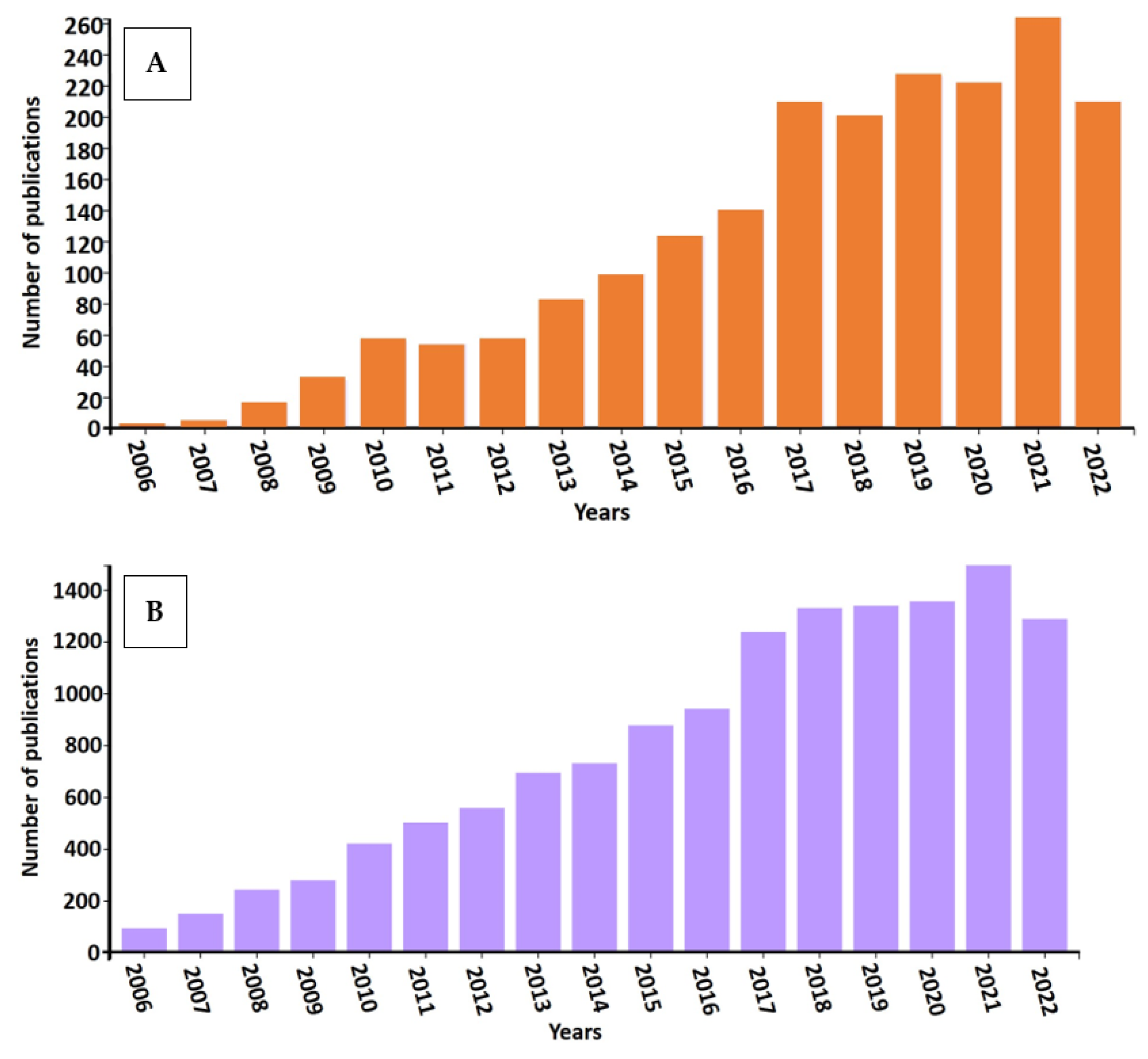
- In this review, we compiled a cross section of the ongoing research on bioelectrochemical systems (BES) with emphasis on the electrochemical biomethane formation. In this endeavor the first observation has been the large number and exponential growth of the relevant scientific publications. In light of the recommenced interest towards renewable energy research and development, this is not surprising.
- We note that the various BES systems developed in numerous laboratories all over the world, comprise a very distinct and diverse collection of the infrastructure, i.e. reaction vessels and parts thereof. This reflects the inventive approaches of the scientists working in the field and the pioneering efforts should be welcomed by the scientific community. This can be rationalized as well, when the multitude reactor designs, electrodes, membranes are selected to perform optimally in specific applications. Unfortunately, the almost chaotic infrastructural assortments make the comparison of the various BES systems extremely difficult. Therefore, it is advised to specify a few “general or basic BES reactor systems” to be included in the related studies as sort of built–in controls to compare to the new or novel system designs.
- This kind of standardization may help the development of BES systems beyond the curiosity driven laboratory scale studies towards industrial applications, which is now hindered by the variety of the diverse laboratory studies using a number of reactor designs and components’ selection.
- A consensus is needed regarding the indicator parameters in the evaluation of the various BES performances.
- Equally important aspect is the need to take into account that all BES systems employs biological components, i.e. pure strains of specific microbes or mixed microbial communities. These microbes do fundamental contribution to the job accomplished and thus they have a great share in the success of the BES electrobiomethanization systems. The complexity of the physiology and biochemistry of these microbial participants significantly alter the success of the electrochemical process. The associated tasks to optimize electrochemistry with microbial fermentation/conversion is largely beyond the scope of this review, only a short sketch of this viewpoint is outlined here. The amalgamation of the electrochemistry and biotechnology issues will be the subject of an upcoming report and many related research.
Author Contributions
Funding
Conflicts of Interest
References
- Ritchie, H.; Roser, M.; Rosado, P. Energy Available online: https://ourworldindata.org/energy.
- Palanisamy, G.; Jung, H.Y.; Sadhasivam, T.; Kurkuri, M.D.; Kim, S.C.; Roh, S.H. A Comprehensive Review on Microbial Fuel Cell Technologies: Processes, Utilization, and Advanced Developments in Electrodes and Membranes. J. Clean. Prod. 2019, 221, 598–621. [CrossRef]
- Wang, J.; Ren, K.; Zhu, Y.; Huang, J.; Liu, S. A Review of Recent Advances in Microbial Fuel Cells: Preparation, Operation, and Application. BioTech 2022, 11, 44. [CrossRef]
- Qin, X.; Lu, X.; Cai, T.; Niu, C.; Han, Y.; Zhang, Z.; Zhu, X.; Zhen, G. Magnetite-Enhanced Bioelectrochemical Stimulation for Biodegradation and Biomethane Production of Waste Activated Sludge. Sci. Total Environ. 2021, 789. [CrossRef]
- Roy, M.; Aryal, N.; Zhang, Y.; Patil, S.A.; Pant, D. Technological Progress and Readiness Level of Microbial Electrosynthesis and Electrofermentation for Carbon Dioxide and Organic Wastes Valorization. Curr. Opin. Green Sustain. Chem. 2022, 35, 100605. [CrossRef]
- Naderi, A.; Kakavandi, B.; Giannakis, S.; Angelidaki, I.; Rezaei Kalantary, R. Putting the Electro-Bugs to Work: A Systematic Review of 22 Years of Advances in Bio-Electrochemical Systems and the Parameters Governing Their Performance. Environ. Res. 2023, 229, 115843. [CrossRef]
- Blasco-Gómez, R.; Batlle-Vilanova, P.; Villano, M.; Balaguer, M.D.; Colprim, J.; Puig, S. On the Edge of Research and Technological Application: A Critical Review of Electromethanogenesis. Int. J. Mol. Sci. 2017, 18, 1–32. [CrossRef]
- Sakakibara, Y.; Araki, K.; Tanaka, T.; Watanabe, T.; Kuroda, M. Denitrification and Meutralization with an Electrochemical and Biological Reactor. Water Sci. Technol. 1994, 30, 151–155. [CrossRef]
- Kuroda, M.; Watanabe, T. CO2 Reduction to Methane and Acetate Using a Bio-Electro Reactor with Immobilized Methanogens and Homoacetogens on Electrodes. Energy Convers. Manag. 1995, 36, 787–790. [CrossRef]
- Call, D.F.; Merrill, M.D.; Logan, B.E. High Surface Area Stainless Steel Brushes as Cathodes in Microbial Electrolysis Cells. Environ. Sci. Technol. 2009, 43, 2179–2183. [CrossRef]
- Parameswaran, P.; Torres, C.I.; Lee, H.S.; Krajmalnik-Brown, R.; Rittmann, B.E. Syntrophic Interactions among Anode Respiring Bacteria (ARB) and Non-ARB in a Biofilm Anode: Electron Balances. Biotechnol. Bioeng. 2009, 103, 513–523. [CrossRef]
- Selembo, P.A.; Merrill, M.D.; Logan, B.E. The Use of Stainless Steel and Nickel Alloys as Low-Cost Cathodes in Microbial Electrolysis Cells. J. Power Sources 2009, 190, 271–278. [CrossRef]
- Liu, H.; Grot, S.; Logan, B.E. Electrochemically Assisted Microbial Production of Hydrogen from Acetate. Environ. Sci. Technol. 2005, 39, 4317–4320. [CrossRef]
- Call, D.; Logan, B.E. Hydrogen Production in a Single Chamber Microbial Electrolysis Cell Lacking a Membrane. Environ. Sci. Technol. 2008, 42, 3401–3406. [CrossRef]
- Ye, Y.; Wang, L.; Chen, Y.; Zhu, S.; Shen, S. High Yield Hydrogen Production in a Single-Chamber Membrane-Less Microbial Electrolysis Cell. Water Sci. Technol. 2010, 61, 721–727. [CrossRef]
- Summers, Z.M.; Fogarty, H.E.; Leang, C.; Franks, A.E.; Malvankar, N.S.; Lovley, D.R. Direct Exchange of Electrons within Aggregates of an Evolved Syntrophic Coculture of Anaerobic Bacteria. Science (80-. ). 2010, 330, 1413–1415. [CrossRef]
- Hara, M.; Onaka, Y.; Kobayashi, H.; Fu, Q.; Kawaguchi, H.; Vilcaez, J.; Sato, K. Mechanism of Electromethanogenic Reduction of CO2 by a Thermophilic Methanogen. Energy Procedia 2013, 37, 7021–7028. [CrossRef]
- Siegert, M.; Yates, M.D.; Call, D.F.; Zhu, X.; Spormann, A.; Logan, B.E. Comparison of Nonprecious Metal Cathode Materials for Methane Production by Electromethanogenesis. ACS Sustain. Chem. Eng. 2014, 2, 910–917. [CrossRef]
- Jiang, Y.; Su, M.; Li, D. Removal of Sulfide and Production of Methane from Carbon Dioxide in Microbial Fuel Cells-Microbial Electrolysis Cell (MFCs-MEC) Coupled System. Appl. Biochem. Biotechnol. 2014, 172, 2720–2731. [CrossRef]
- Jiang, Y.; Su, M.; Zhang, Y.; Zhan, G.; Tao, Y.; Li, D. Bioelectrochemical Systems for Simultaneously Production of Methane and Acetate from Carbon Dioxide at Relatively High Rate. Int. J. Hydrogen Energy 2013, 38, 3497–3502. [CrossRef]
- Liu, W.; He, Z.; Yang, C.; Zhou, A.; Guo, Z.; Liang, B.; Varrone, C.; Wang, A.J. Microbial Network for Waste Activated Sludge Cascade Utilization in an Integrated System of Microbial Electrolysis and Anaerobic Fermentation. Biotechnol. Biofuels 2016, 9. [CrossRef]
- Ma, X.; Li, Z.; Zhou, A.; Yue, X. Energy Recovery from Tubular Microbial Electrolysis Cell with Stainless Steel Mesh as Cathode. R. Soc. Open Sci. 2017, 4, 0–7. [CrossRef]
- Shen, R.X.; Lu, J.W.; Zhu, Z.B.; Duan, N.; Lu, H.F.; Zhang, Y.H.; Liu, Z.D. Effects of Organic Strength on Performance of Microbial Electrolysis Cell Fed with Hydrothermal Liquefied Wastewater. Int. J. Agric. Biol. Eng. 2017, 10, 206–217. [CrossRef]
- Marshall, C.W.; Ross, D.E.; Fichot, E.B.; Norman, R.S.; May, H.D. Electrosynthesis of Commodity Chemicals by an Autotrophic Microbial Community. Appl. Environ. Microbiol. 2012, 78, 8412–8420. [CrossRef]
- Enzmann, F.; Holtmann, D. Rational Scale-Up of a Methane Producing Bioelectrochemical Reactor to 50 L Pilot Scale. Chem. Eng. Sci. 2019, 207, 1148–1158. [CrossRef]
- Villano, M.; Aulenta, F.; Ciucci, C.; Ferri, T.; Giuliano, A.; Majone, M. Bioelectrochemical Reduction of CO2 to CH4 via Direct and Indirect Extracellular Electron Transfer by a Hydrogenophilic Methanogenic Culture. Bioresour. Technol. 2010, 101, 3085–3090. [CrossRef]
- Kuramochi, Y.; Fu, Q.; Kobayashi, H.; Ikarashi, M.; Wakayama, T.; Kawaguchi, H.; Vilcaez, J.; Maeda, H.; Sato, K. Electromethanogenic CO2 Conversion by Subsurface-Reservoir Microorganisms. Energy Procedia 2013, 37, 7014–7020. [CrossRef]
- Geppert, F.; Liu, D.; van Eerten-Jansen, M.; Weidner, E.; Buisman, C.; ter Heijne, A. Bioelectrochemical Power-to-Gas: State of the Art and Future Perspectives. Trends Biotechnol. 2016, 34, 879–894. [CrossRef]
- Yu, J.; Kim, S.; Kwon, O.S. Effect of Applied Voltage and Temperature on Methane Production and Microbial Community in Microbial Electrochemical Anaerobic Digestion Systems Treating Swine Manure. J. Ind. Microbiol. Biotechnol. 2019, 46, 911–923. [CrossRef]
- Ceballos-Escalera, A.; Molognoni, D.; Bosch-Jimenez, P.; Shahparasti, M.; Bouchakour, S.; Luna, A.; Guisasola, A.; Borràs, E.; Della Pirriera, M. Bioelectrochemical Systems for Energy Storage: A Scaled-up Power-to-Gas Approach. Appl. Energy 2020, 260, 114138. [CrossRef]
- Saratale, R.G.; Saratale, G.D.; Pugazhendhi, A.; Zhen, G.; Kumar, G.; Kadier, A.; Sivagurunathan, P. Microbiome Involved in Microbial Electrochemical Systems (MESs): A Review. Chemosphere 2017, 177, 176–188. [CrossRef]
- Lee, M.; Nagendranatha Reddy, C.; Min, B. In Situ Integration of Microbial Electrochemical Systems into Anaerobic Digestion to Improve Methane Fermentation at Different Substrate Concentrations. Int. J. Hydrogen Energy 2019, 44, 2380–2389. [CrossRef]
- van Eerten-Jansen, M.C.A.A.; Jansen, N.C.; Plugge, C.M.; de Wilde, V.; Buisman, C.J.N.; ter Heijne, A. Analysis of the Mechanisms of Bioelectrochemical Methane Production by Mixed Cultures. J. Chem. Technol. Biotechnol. 2015, 90, 963–970. [CrossRef]
- Angelidaki, I.; Xie, L.; Luo, G.; Zhang, Y.; Oechsner, H.; Lemmer, A.; Munoz, R.; Kougias, P.G. Biogas Upgrading: Current and Emerging Technologies; 2nd ed.; Elsevier Inc., 2019; ISBN 9780128168561.
- Batlle-Vilanova, P.; Puig, S.; Gonzalez-Olmos, R.; Vilajeliu-Pons, A.; Balaguer, M.D.; Colprim, J. Deciphering the Electron Transfer Mechanisms for Biogas Upgrading to Biomethane within a Mixed Culture Biocathode. RSC Adv. 2015, 5, 52243–52251. [CrossRef]
- Noori, M.T.; Min, B. Fundamentals and Recent Progress in Bioelectrochemical System-Assisted Biohythane Production. Bioresour. Technol. 2022, 361, 127641. [CrossRef]
- Luo, S.; Jain, A.; Aguilera, A.; He, Z. Effective Control of Biohythane Composition through Operational Strategies in an Innovative Microbial Electrolysis Cell. Appl. Energy 2017, 206, 879–886. [CrossRef]
- Dubé, C.D.; Guiot, S.R. Direct Interspecies Electron Transfer in Anaerobic Digestion: A Review. In Biogas Science and Technology; Springer International Publishing, 2015; pp. 101–115 ISBN 9783319219936.
- Sydow, A.; Krieg, T.; Mayer, F.; Schrader, J.; Holtmann, D. Electroactive Bacteria—Molecular Mechanisms and Genetic Tools. Appl. Microbiol. Biotechnol. 2014, 98, 8481–8495. [CrossRef]
- Holmes, D.E.; Zhou, J.; Smith, J.A.; Wang, C.; Liu, X.; Lovley, D.R.; Yang, Y. Different Outer Membrane c -type Cytochromes Are Involved in Direct Interspecies Electron Transfer to Geobacter or Methanosarcina Species . mLife 2022, 1, 272–286. [CrossRef]
- Cheng, S.; Xing, D.; Call, D.F.; Logan, B.E. Direct Biological Conversion of Electrical Current into Methane by Electromethanogenesis. Environ. Sci. Technol. 2009, 43, 3953–3958. [CrossRef]
- Cerrillo, M.; Burgos, L.; Bonmatí, A. Biogas Upgrading and Ammonia Recovery from Livestock Manure Digestates in a Combined Electromethanogenic Biocathode—Hydrophobic Membrane System. Energies 2021, 14. [CrossRef]
- Logan, B.E.; Rossi, R.; Ragab, A.; Saikaly, P.E. Electroactive Microorganisms in Bioelectrochemical Systems. Nat. Rev. Microbiol. 2019, 17, 307–319. [CrossRef]
- Guang, L.; Koomson, D.A.; Jingyu, H.; Ewusi-Mensah, D.; Miwornunyuie, N. Performance of Exoelectrogenic Bacteria Used in Microbial Desalination Cell Technology. Int. J. Environ. Res. Public Health 2020, 17, 10–12. [CrossRef]
- Cheng, K.Y.; Ho, G.; Cord-Ruwisch, R. Novel Methanogenic Rotatable Bioelectrochemical System Operated with Polarity Inversion. Environ. Sci. Technol. 2011, 45, 796–802. [CrossRef]
- Villano, M.; Scardala, S.; Aulenta, F.; Majone, M. Carbon and Nitrogen Removal and Enhanced Methane Production in a Microbial Electrolysis Cell. Bioresour. Technol. 2013, 130, 366–371. [CrossRef]
- Park, S.G.; Rhee, C.; Shin, S.G.; Shin, J.; Mohamed, H.O.; Choi, Y.J.; Chae, K.J. Methanogenesis Stimulation and Inhibition for the Production of Different Target Electrobiofuels in Microbial Electrolysis Cells through an On-Demand Control Strategy Using the Coenzyme M and 2-Bromoethanesulfonate. Environ. Int. 2019, 131, 105006. [CrossRef]
- Zhang, Z.; Song, Y.; Zheng, S.; Zhen, G.; Lu, X.; Takuro, K.; Xu, K.; Bakonyi, P. Electro-Conversion of Carbon Dioxide (CO2) to Low-Carbon Methane by Bioelectromethanogenesis Process in Microbial Electrolysis Cells: The Current Status and Future Perspective. Bioresour. Technol. 2019, 279, 339–349. [CrossRef]
- Giddings, C.G.S.; Nevin, K.P.; Woodward, T.; Lovley, D.R.; Butler, C.S. Simplifying Microbial Electrosynthesis Reactor Design. Front. Microbiol. 2015, 6, 1–6. [CrossRef]
- Roy, M.; Aryal, N.; Zhang, Y.; Patil, S.A.; Pant, D. Technological Progress and Readiness Level of Microbial Electrosynthesis and Electrofermentation for Carbon Dioxide and Organic Wastes Valorization. Curr. Opin. Green Sustain. Chem. 2022, 35. [CrossRef]
- Cai, W.; Cui, K.; Liu, Z.; Jin, X.; Chen, Q.; Guo, K.; Wang, Y. An Electrolytic-Hydrogen-Fed Moving Bed Biofilm Reactor for Efficient Microbial Electrosynthesis of Methane from CO2. Chem. Eng. J. 2022, 428, 132093. [CrossRef]
- Jourdin, L.; Freguia, S.; Flexer, V.; Keller, J. Bringing High-Rate, CO2-Based Microbial Electrosynthesis Closer to Practical Implementation through Improved Electrode Design and Operating Conditions. Environ. Sci. Technol. 2016, 50, 1982–1989. [CrossRef]
- Li, X.; Liu, G.; He, Z. Flexible Control of Biohythane Composition and Production by Dual Cathodes in a Bioelectrochemical System. Bioresour. Technol. 2020, 295, 122270. [CrossRef]
- Rosenbaum, M.; Aulenta, F.; Villano, M.; Angenent, L.T. Cathodes as Electron Donors for Microbial Metabolism: Which Extracellular Electron Transfer Mechanisms Are Involved? Bioresour. Technol. 2011, 102, 324–333. [CrossRef]
- Enzmann, F.; Mayer, F.; Stöckl, M.; Mangold, K.M.; Hommel, R.; Holtmann, D. Transferring Bioelectrochemical Processes from H-Cells to a Scalable Bubble Column Reactor. Chem. Eng. Sci. 2019, 193, 133–143. [CrossRef]
- Hassanein, A.; Witarsa, F.; Lansing, S.; Qiu, L.; Liang, Y. Bio-Electrochemical Enhancement of Hydrogen and Methane Production in a Combined Anaerobic Digester (AD) and Microbial Electrolysis Cell (MEC) from Dairy Manure. Sustain. 2020, 12, 1–12. [CrossRef]
- Amrut Pawar, A.; Karthic, A.; Lee, S.; Pandit, S.; Jung, S.P. Microbial Electrolysis Cells for Electromethanogenesis: Materials, Configurations and Operations. Environ. Eng. Res. 2020, 27, 200484–0. [CrossRef]
- Geppert, F.; Liu, D.; Weidner, E.; Heijne, A. ter Redox-Flow Battery Design for a Methane-Producing Bioelectrochemical System. Int. J. Hydrogen Energy 2019, 44, 21464–21469. [CrossRef]
- Tanaka, K.; Yokoe, S.; Igarashi, K.; Takashino, M.; Ishikawa, M.; Hori, K.; Nakanishi, S.; Kato, S. Extracellular Electron Transfer via Outer Membrane Cytochromes in a Methanotrophic Bacterium Methylococcus Capsulatus (Bath). Front. Microbiol. 2018, 9, 1–7. [CrossRef]
- Nguyen, L.N.; Vu, M.T.; Abu Hasan Johir, M.; Pernice, M.; Ngo, H.H.; Zdarta, J.; Jesionowski, T.; Nghiem, L.D. Promotion of Direct Interspecies Electron Transfer and Potential Impact of Conductive Materials in Anaerobic Digestion and Its Downstream Processing - a Critical Review. Bioresour. Technol. 2021, 341, 125847. [CrossRef]
- Baek, G.; Kim, J.; Kim, J.; Lee, C. Role and Potential of Direct Interspecies Electron Transfer in Anaerobic Digestion. Energies 2018, 11. [CrossRef]
- Umar, M.F.; Abbas, S.Z.; Mohamad Ibrahim, M.N.; Ismail, N.; Rafatullah, M. Insights into Advancements and Electrons Transfer Mechanisms of Electrogens in Benthic Microbial Fuel Cells. Membranes (Basel). 2020, 10, 1–18. [CrossRef]
- Paquete, C.M.; Rosenbaum, M.A.; Bañeras, L.; Rotaru, A.E.; Puig, S. Let’s Chat: Communication between Electroactive Microorganisms. Bioresour. Technol. 2022, 347. [CrossRef]
- Thapa, B. Sen; Pandit, S.; Patwardhan, S.B.; Tripathi, S.; Mathuriya, A.S.; Gupta, P.K.; Lal, R.B.; Tusher, T.R. Application of Microbial Fuel Cell (MFC) for Pharmaceutical Wastewater Treatment: An Overview and Future Perspectives. Sustain. 2022, 14. [CrossRef]
- Aryal, N.; Ammam, F.; Patil, S.A.; Pant, D. An Overview of Cathode Materials for Microbial Electrosynthesis of Chemicals from Carbon Dioxide. Green Chem. 2017, 19, 5748–5760. [CrossRef]
- Paritosh, K.; Yadav, M.; Chawade, A.; Sahoo, D.; Kesharwani, N.; Pareek, N.; Vivekanand, V. Additives as a Support Structure for Specific Biochemical Activity Boosts in Anaerobic Digestion: A Review. Front. Energy Res. 2020, 8, 1–17. [CrossRef]
- Electrical Effects Accompanying the Decomposition of Organic Compounds. Proc. R. Soc. London. Ser. B, Contain. Pap. a Biol. Character 1911, 84, 260–276. [CrossRef]
- Daniels, L.; Belay, N.; Rajagopal, B.S.; Weimer, P.J. Bacterial Methanogenesis and Growth from CO2 with Elemental Iron as the Sole Source of Electrons. Science (80-. ). 1987, 237, 509–511. [CrossRef]
- Rotaru, A.E.; Shrestha, P.M.; Liu, F.; Shrestha, M.; Shrestha, D.; Embree, M.; Zengler, K.; Wardman, C.; Nevin, K.P.; Lovley, D.R. A New Model for Electron Flow during Anaerobic Digestion: Direct Interspecies Electron Transfer to Methanosaeta for the Reduction of Carbon Dioxide to Methane. Energy Environ. Sci. 2014, 7, 408–415. [CrossRef]
- Shirkosh, M.; Hojjat, Y.; Mardanpour, M.M. Boosting Microfluidic Microbial Fuel Cells Performance via Investigating Electron Transfer Mechanisms, Metal-Based Electrodes, and Magnetic Field Effect. Sci. Rep. 2022, 12, 1–16. [CrossRef]
- Nawaz, A.; ul Haq, I.; Qaisar, K.; Gunes, B.; Raja, S.I.; Mohyuddin, K.; Amin, H. Microbial Fuel Cells: Insight into Simultaneous Wastewater Treatment and Bioelectricity Generation. Process Saf. Environ. Prot. 2022, 161, 357–373. [CrossRef]
- Baby, M.G.; Ahammed, M.M. Nutrient Removal and Recovery from Wastewater by Microbial Fuel Cell-Based Systems – A Review. Water Sci. Technol. 2022, 86, 29–55. [CrossRef]
- Ahmed, S.F.; Mofijur, M.; Islam, N.; Parisa, T.A.; Rafa, N.; Bokhari, A.; Klemeš, J.J.; Indra Mahlia, T.M. Insights into the Development of Microbial Fuel Cells for Generating Biohydrogen, Bioelectricity, and Treating Wastewater. Energy 2022, 254. [CrossRef]
- Van Eerten-Jansen, M.C.A.A.; Heijne, A. Ter; Buisman, C.J.N.; Hamelers, H.V.M. Microbial Electrolysis Cells for Production of Methane from CO2: Long-Term Performance and Perspectives. Int. J. Energy Res. 2012, 36, 809–819. [CrossRef]
- Rabaey, K.; Rozendal, R.A. Microbial Electrosynthesis - Revisiting the Electrical Route for Microbial Production. Nat. Rev. Microbiol. 2010, 8, 706–716. [CrossRef]
- Schlager, S.; Haberbauer, M.; Fuchsbauer, A.; Hemmelmair, C.; Dumitru, L.M.; Hinterberger, G.; Neugebauer, H.; Sariciftci, N.S. Bio-Electrocatalytic Application of Microorganisms for Carbon Dioxide Reduction to Methane. ChemSusChem 2017, 10, 226–233. [CrossRef]
- Rousseau, R.; Ketep, S.F.; Etcheverry, L.; Délia, M.L.; Bergel, A. Microbial Electrolysis Cell (MEC): A Step Ahead towards Hydrogen-Evolving Cathode Operated at High Current Density. Bioresour. Technol. Reports 2020, 9, 100399. [CrossRef]
- Yin, Q.; Zhu, X.; Zhan, G.; Bo, T.; Yang, Y.; Tao, Y.; He, X.; Li, D.; Yan, Z. Enhanced Methane Production in an Anaerobic Digestion and Microbial Electrolysis Cell Coupled System with Co-Cultivation of Geobacter and Methanosarcina. J. Environ. Sci. (China) 2016, 42, 210–214. [CrossRef]
- Zhen, G.; Kobayashi, T.; Lu, X.; Xu, K. Understanding Methane Bioelectrosynthesis from Carbon Dioxide in a Two-Chamber Microbial Electrolysis Cells (MECs) Containing a Carbon Biocathode. Bioresour. Technol. 2015, 186, 141–148. [CrossRef]
- Zhen, G.; Lu, X.; Kobayashi, T.; Kumar, G.; Xu, K. Promoted Electromethanosynthesis in a Two-Chamber Microbial Electrolysis Cells (MECs) Containing a Hybrid Biocathode Covered with Graphite Felt (GF). Chem. Eng. J. 2016, 284, 1146–1155. [CrossRef]
- Fu, Q.; Kuramochi, Y.; Fukushima, N.; Maeda, H.; Sato, K.; Kobayashi, H. Bioelectrochemical Analyses of the Development of a Thermophilic Biocathode Catalyzing Electromethanogenesis. Environ. Sci. Technol. 2015, 49, 1225–1232. [CrossRef]
- Liu, S.Y.; Charles, W.; Ho, G.; Cord-Ruwisch, R.; Cheng, K.Y. Bioelectrochemical Enhancement of Anaerobic Digestion: Comparing Single- and Two-Chamber Reactor Configurations at Thermophilic Conditions. Bioresour. Technol. 2017, 245, 1168–1175. [CrossRef]
- Liu, Q.; Ren, Z.J.; Huang, C.; Liu, B.; Ren, N.; Xing, D. Multiple Syntrophic Interactions Drive Biohythane Production from Waste Sludge in Microbial Electrolysis Cells. Biotechnol. Biofuels 2016, 9, 1–10. [CrossRef]
- Dou, Z.; Dykstra, C.M.; Pavlostathis, S.G. Bioelectrochemically Assisted Anaerobic Digestion System for Biogas Upgrading and Enhanced Methane Production. Sci. Total Environ. 2018, 633, 1012–1021. [CrossRef]
- Giang, H.; Zhang, J.; Zhu, Z.; Suni, I.I.; Liang, Y. Single-Chamber Microbial Electrochemical Cell for CH4 Production from CO2 Utilizing a Microbial Consortium. Int. J. Energy Res. 2018, 42, 1308–1315. [CrossRef]
- Park, J.; Lee, B.; Tian, D.; Jun, H. Bioelectrochemical Enhancement of Methane Production from Highly Concentrated Food Waste in a Combined Anaerobic Digester and Microbial Electrolysis Cell. Bioresour. Technol. 2018, 247, 226–233. [CrossRef]
- Tartakovsky, B.; Mehta, P.; Bourque, J.S.; Guiot, S.R. Electrolysis-Enhanced Anaerobic Digestion of Wastewater. Bioresour. Technol. 2011, 102, 5685–5691. [CrossRef]
- Bo, T.; Zhu, X.; Zhang, L.; Tao, Y.; He, X.; Li, D.; Yan, Z. A New Upgraded Biogas Production Process: Coupling Microbial Electrolysis Cell and Anaerobic Digestion in Single-Chamber, Barrel-Shape Stainless Steel Reactor. Electrochem. commun. 2014, 45, 67–70. [CrossRef]
- Cusick, R.D.; Bryan, B.; Parker, D.S.; Merrill, M.D.; Mehanna, M.; Kiely, P.D.; Liu, G.; Logan, B.E. Performance of a Pilot-Scale Continuous Flow Microbial Electrolysis Cell Fed Winery Wastewater. Appl. Microbiol. Biotechnol. 2011, 89, 2053–2063. [CrossRef]
- Van Eerten-Jansen, M.C.A.A.; Veldhoen, A.B.; Plugge, C.M.; Stams, A.J.M.; Buisman, C.J.N.; Ter Heijne, A. Microbial Community Analysis of a Methane-Producing Biocathode in a Bioelectrochemical System. Archaea 2013, 2013. [CrossRef]
- Zeppilli, M.; Simoni, M.; Paiano, P.; Majone, M. Two-Side Cathode Microbial Electrolysis Cell for Nutrients Recovery and Biogas Upgrading. Chem. Eng. J. 2019, 370, 466–476. [CrossRef]
- Liu, C.; Yuan, X.; Gu, Y.; Chen, H.; Sun, D.; Li, P.; Li, M.; Dang, Y.; Smith, J.A.; Holmes, D.E. Enhancement of Bioelectrochemical CO 2 Reduction with a Carbon Brush Electrode via Direct Electron Transfer. ACS Sustain. Chem. Eng. 2020, 8, 11368–11375. [CrossRef]
- Liu, C.; Sun, D.; Zhao, Z.; Dang, Y.; Holmes, D.E. Methanothrix Enhances Biogas Upgrading in Microbial Electrolysis Cell via Direct Electron Transfer. Bioresour. Technol. 2019, 291, 121877. [CrossRef]
- Fu, X.Z.; Li, J.; Pan, X.R.; Huang, L.; Li, C.X.; Cui, S.; Liu, H.Q.; Tan, Z.L.; Li, W.W. A Single Microbial Electrochemical System for CO2 Reduction and Simultaneous Biogas Purification, Upgrading and Sulfur Recovery. Bioresour. Technol. 2020, 297, 122448. [CrossRef]
- Luo, X.; Zhang, F.; Liu, J.; Zhang, X.; Huang, X.; Logan, B.E. Methane Production in Microbial Reverse-Electrodialysis Methanogenesis Cells (MRMCs) Using Thermolytic Solutions. Environ. Sci. Technol. 2014, 48, 8911–8918. [CrossRef]
- Xiao, S.; Li, Z.; Fu, Q.; Li, Y.; Li, J.; Zhang, L.; Liao, Q.; Zhu, X. Hybrid Microbial Photoelectrochemical System Reduces CO2 to CH4 with 1.28% Solar Energy Conversion Efficiency. Chem. Eng. J. 2020, 390, 124530. [CrossRef]
- Martín, A.J.; Larrazábal, G.O.; Pérez-Ramírez, J. Towards Sustainable Fuels and Chemicals through the Electrochemical Reduction of CO2: Lessons from Water Electrolysis. Green Chem. 2015, 17, 5114–5130. [CrossRef]
- Clauwaert, P.; Tolêdo, R.; van der Ha, D.; Crab, R.; Verstraete, W.; Hu, H.; Udert, K.M.; Rabaey, K. Combining Biocatalyzed Electrolysis with Anaerobic Digestion. Water Sci. Technol. 2008, 57, 575–579. [CrossRef]
- Villano, M.; Monaco, G.; Aulenta, F.; Majone, M. Electrochemically Assisted Methane Production in a Biofilm Reactor. J. Power Sources 2011, 196, 9467–9472. [CrossRef]
- Call, D.F.; Logan, B.E. A Method for High Throughput Bioelectrochemical Research Based on Small Scale Microbial Electrolysis Cells. Biosens. Bioelectron. 2011, 26, 4526–4531. [CrossRef]
- Batlle-Vilanova, P.; Rovira-Alsina, L.; Puig, S.; Balaguer, M.D.; Icaran, P.; Monsalvo, V.M.; Rogalla, F.; Colprim, J. Biogas Upgrading, CO2 Valorisation and Economic Revaluation of Bioelectrochemical Systems through Anodic Chlorine Production in the Framework of Wastewater Treatment Plants. Sci. Total Environ. 2019, 690, 352–360. [CrossRef]
- Zeppilli, M.; Mattia, A.; Villano, M.; Majone, M. Three-Chamber Bioelectrochemical System for Biogas Upgrading and Nutrient Recovery. Fuel Cells 2017, 17, 593–600. [CrossRef]
- Clauwaert, P.; Verstraete, W. Methanogenesis in Membraneless Microbial Electrolysis Cells. Appl. Microbiol. Biotechnol. 2009, 82, 829–836. [CrossRef]
- Hou, Y.; Zhang, R.; Luo, H.; Liu, G.; Kim, Y.; Yu, S.; Zeng, J. Microbial Electrolysis Cell with Spiral Wound Electrode for Wastewater Treatment and Methane Production. Process Biochem. 2015, 50, 1103–1109. [CrossRef]
- Call, D.; Logan, B.E. Hydrogen Production in a Single Chamber Microbial Electrolysis Cell Lacking a Membrane. Environ. Sci. Technol. 2008, 42, 3401–3406. [CrossRef]
- Ditzig, J.; Liu, H.; Logan, B.E. Production of Hydrogen from Domestic Wastewater Using a Bioelectrochemically Assisted Microbial Reactor (BEAMR). Int. J. Hydrogen Energy 2007, 32, 2296–2304. [CrossRef]
- Guo, K.; Tang, X.; Du, Z.; Li, H. Hydrogen Production from Acetate in a Cathode-on-Top Single-Chamber Microbial Electrolysis Cell with a Mipor Cathode. Biochem. Eng. J. 2010, 51, 48–52. [CrossRef]
- Butler, C.S.; Lovley, D.R. How to Sustainably Feed a Microbe: Strategies for Biological Production of Carbon-Based Commodities with Renewable Electricity. Front. Microbiol. 2016, 7, 1–6. [CrossRef]
- Allen, M.J. Symposium on Bioelectrochemistry of Microorganisms. II. Electrochemical Aspects of Metabolism. Bacteriol. Rev. 1966, 30, 80–93. [CrossRef]
- Hongo, M.; Iwahara, M. Application of Electro-Energizing Method to L-Glutamic Acid Fermentation. Agric. Biol. Chem. 1979, 43, 2075–2081. [CrossRef]
- Nevin, K.P.; Woodard, T.L.; Franks, A.E.; Summers, Z.M.; Lovley, D.R. Microbial Electrosynthesis: Feeding Microbes Electricity To Convert Carbon Dioxide and Water to Multicarbon Extracellular Organic Compounds. MBio 2010, 1, 1–4. [CrossRef]
- Zhou, H.; Xing, D.; Xu, M.; Su, Y.; Ma, J.; Angelidaki, I.; Zhang, Y. Optimization of a Newly Developed Electromethanogenesis for the Highest Record of Methane Production. J. Hazard. Mater. 2020, 124363. [CrossRef]
- Villano, M.; Aulenta, F.; Ciucci, C.; Ferri, T.; Giuliano, A.; Majone, M. Bioelectrochemical Reduction of CO2 to CH4 via Direct and Indirect Extracellular Electron Transfer by a Hydrogenophilic Methanogenic Culture. Bioresour. Technol. 2010, 101, 3085–3090. [CrossRef]
- Krieg, T.; Madjarov, J.; Rosa, L.F.M.; Enzmann, F.; Harnisch, F.; Holtmann, D.; Rabaey, K. Reactors for Microbial Electrobiotechnology. Adv. Biochem. Eng. Biotechnol. 2019, 167, 231–271. [CrossRef]
- Kokkoli, A.; Zhang, Y.; Angelidaki, I. Microbial Electrochemical Separation of CO2 for Biogas Upgrading. Bioresour. Technol. 2018, 247, 380–386. [CrossRef]
- Aryal, N.; Zhang, Y.; Bajracharya, S.; Pant, D.; Chen, X. Microbial Electrochemical Approaches of Carbon Dioxide Utilization for Biogas Upgrading. Chemosphere 2022, 291, 132843. [CrossRef]
- Gao, T.; Zhang, H.; Xu, X.; Teng, J. Integrating Microbial Electrolysis Cell Based on Electrochemical Carbon Dioxide Reduction into Anaerobic Osmosis Membrane Reactor for Biogas Upgrading. Water Res. 2021, 190, 116679. [CrossRef]
- Xu, T. Ion Exchange Membranes: State of Their Development and Perspective. J. Memb. Sci. 2005, 263, 1–29. [CrossRef]
- Frilette, V.J. PREPARATION AND CHARACTERIZATION OF BIPOLAR ION-EXCHANGE MEMBRANES. Permut. Co. 1955, 60, 435–439.
- Parekh, A. Recent Developments of Proton Exchange Membranes for PEMFC: A Review. Front. Energy Res. 2022, 10. [CrossRef]
- Ogungbemi, E.; Ijaodola, O.; Khatib, F.N.; Wilberforce, T.; El Hassan, Z.; Thompson, J.; Ramadan, M.; Olabi, A.G. Fuel Cell Membranes – Pros and Cons. Energy 2019, 172, 155–172. [CrossRef]
- Zuo, Z.; Fu, Y.; Manthiram, A. Novel Blend Membranes Based on Acid-Base Interactions for Fuel Cells. Polymers (Basel). 2012, 4, 1627–1644. [CrossRef]
- Peighambardoust, S.J.; Rowshanzamir, S.; Amjadi, M. Review of the Proton Exchange Membranes for Fuel Cell Applications; Elsevier Ltd, 2010; Vol. 35; ISBN 2177491223.
- Jiao, K.; Xuan, J.; Du, Q.; Bao, Z.; Xie, B.; Wang, B.; Zhao, Y.; Fan, L.; Wang, H.; Hou, Z.; et al. Designing the next Generation of Proton-Exchange Membrane Fuel Cells. Nature 2021, 595, 361–369. [CrossRef]
- Atifi, A.; Mounir, H.; El Marjani, A. Effect of Internal Current, Fuel Crossover, and Membrane Thickness on a PEMFC Performance. Proc. 2014 Int. Renew. Sustain. Energy Conf. IRSEC 2014 2014, 907–912. [CrossRef]
- Peterson, D.S. Encyclopedia of Microfluidics and Nanofluidics. Encycl. Microfluid. Nanofluidics 2013, 3–7. [CrossRef]
- Belafi-Bako, K.; Bakonyi, P. Integration of Membranes and Bioreactors;
- Strathmann, H.; Grabowski, A.; Eigenberger, G. Ion-Exchange Membranes in the Chemical Process Industry. Ind. Eng. Chem. Res. 2013, 52, 10364–10379. [CrossRef]
- Ran, J.; Wu, L.; He, Y.; Yang, Z.; Wang, Y.; Jiang, C.; Ge, L.; Bakangura, E.; Xu, T. Ion Exchange Membranes: New Developments and Applications. J. Memb. Sci. 2017, 522, 267–291. [CrossRef]
- Takamuku, S.; Wohlfarth, A.; Manhart, A.; Räder, P.; Jannasch, P. Hypersulfonated Polyelectrolytes: Preparation, Stability and Conductivity. Polym. Chem. 2015, 6, 1267–1274. [CrossRef]
- Tong, X.; Zhang, B.; Fan, Y.; Chen, Y. Mechanism Exploration of Ion Transport in Nanocomposite Cation Exchange Membranes. ACS Appl. Mater. Interfaces 2017, 9, 13491–13499. [CrossRef]
- Vengatesan, S.; Santhi, S.; Sozhan, G.; Ravichandran, S.; Davidson, D.J.; Vasudevan, S. Novel Cross-Linked Anion Exchange Membrane Based on Hexaminium Functionalized Poly(Vinylbenzyl Chloride). RSC Adv. 2015, 5, 27365–27371. [CrossRef]
- Babiak, P.; Schaffer-Harris, G.; Kainuma, M.; Fedorovich, V.; Goryanin, I. Development of a New Hydrogel Anion Exchange Membrane for Swine Wastewater Treatment. Membranes (Basel). 2022, 12. [CrossRef]
- Das, G.; Choi, J.H.; Nguyen, P.K.T.; Kim, D.J.; Yoon, Y.S. Anion Exchange Membranes for Fuel Cell Application: A Review. Polymers (Basel). 2022, 14. [CrossRef]
- Blommaert, M.A.; Aili, D.; Tufa, R.A.; Li, Q.; Smith, W.A.; Vermaas, D.A. Insights and Challenges for Applying Bipolar Membranes in Advanced Electrochemical Energy Systems. ACS Energy Lett. 2021, 6, 2539–2548. [CrossRef]
- Liu, L.; Wang, C.; He, Z.; Das, R.; Dong, B.; Xie, X.; Guo, Z. An Overview of Amphoteric Ion Exchange Membranes for Vanadium Redox Flow Batteries. J. Mater. Sci. Technol. 2021, 69, 212–227. [CrossRef]
- Friess, K. Mosaic Membranes. In Encyclopedia of Membranes; Springer Berlin Heidelberg: Berlin, Heidelberg, 2014; Vol. 47, pp. 1–2.
- Besha, A.T.; Tsehaye, M.T.; Aili, D.; Zhang, W.; Tufa, R.A. Design of Monovalent Ion Selective Membranes for Reducing the Impacts of Multivalent Ions in Reverse Electrodialysis. Membranes (Basel). 2020, 10. [CrossRef]
- Guo, K.; Prévoteau, A.; Patil, S.A.; Rabaey, K. Engineering Electrodes for Microbial Electrocatalysis. Curr. Opin. Biotechnol. 2015, 33, 149–156. [CrossRef]
- Das, P.; Banerjee, S.; Das, N.C. Polymer-Graphene Composite in Aerospace Engineering. In Polymer Nanocomposites Containing Graphene; Elsevier, 2022; Vol. 13, pp. 683–711 ISBN 9780128216392.
- Mahmoud, R.H.; Gomaa, O.M.; Hassan, R.Y.A. Bio-Electrochemical Frameworks Governing Microbial Fuel Cell Performance: Technical Bottlenecks and Proposed Solutions. RSC Adv. 2022, 12, 5749–5764. [CrossRef]
- Pierson, H.O. Graphite Structure and Properties. Handb. Carbon, Graph. Diamonds Fullerenes 1993, 43–69. [CrossRef]
- Liu, C.; Xiao, J.; Li, H.; Chen, Q.; Sun, D.; Cheng, X.; Li, P.; Dang, Y.; Smith, J.A.; Holmes, D.E. High Efficiency In-Situ Biogas Upgrading in a Bioelectrochemical System with Low Energy Input. Water Res. 2021, 197, 117055. [CrossRef]
- Feng, Q.; Song, Y.C.; Ahn, Y. Electroactive Microorganisms in Bulk Solution Contribute Significantly to Methane Production in Bioelectrochemical Anaerobic Reactor. Bioresour. Technol. 2018, 259, 119–127. [CrossRef]
- Bharati, R.; Sundaramurthy, S.; Thakur, C. Nanomaterials and Food-Processing Wastewater; Elsevier Inc., 2017; ISBN 9780128043004.
- Gomez-Gualdrón, D.A.; Burgos, J.C.; Yu, J.; Balbuena, P.B. Carbon Nanotubes: Engineering Biomedical Applications; 2011; Vol. 104; ISBN 9780124160200.
- Peigney, A.; Laurent, C.; Flahaut, E.; Bacsa, R.R.; Rousset, A. Specific Surface Area of Carbon Nanotubes and Bundles of Carbon Nanotubes. Carbon N. Y. 2001, 39, 507–514. [CrossRef]
- Kang, S.; Mauter, M.S.; Elimelech, M. Physicochemical Determinants of Multiwalled Carbon Nanotube Bacterial Cytotoxicity. Environ. Sci. Technol. 2008, 42, 7528–7534. [CrossRef]
- Yang, S.; Han, S.; Yun, Y.M.; Kang, S. Stimulation of Biomethane Productivity in Anaerobic Digestion Using Electro-Conductive Carbon-Nanotube Hollow-Fiber Media. Minerals 2021, 11, 1–10. [CrossRef]
- Deng, F.; Sun, J.; Hu, Y.; Chen, J.; Li, S.; Chen, J.; Zhang, Y. Biofilm Evolution and Viability during: In Situ Preparation of a Graphene/Exoelectrogen Composite Biofilm Electrode for a High-Performance Microbial Fuel Cell. RSC Adv. 2017, 7, 42172–42179. [CrossRef]
- Zhou, H.; Xing, D.; Xu, M.; Su, Y.; Zhang, Y. Biogas Upgrading and Energy Storage via Electromethanogenesis Using Intact Anaerobic Granular Sludge as Biocathode. Appl. Energy 2020, 269, 115101. [CrossRef]
- Kim, K.R.; Kang, J.; Chae, K.J. Improvement in Methanogenesis by Incorporating Transition Metal Nanoparticles and Granular Activated Carbon Composites in Microbial Electrolysis Cells. Int. J. Hydrogen Energy 2017, 42, 27623–27629. [CrossRef]
- Sangeetha, T.; Guo, Z.; Liu, W.; Cui, M.; Yang, C.; Wang, L.; Wang, A. Cathode Material as an Influencing Factor on Beer Wastewater Treatment and Methane Production in a Novel Integrated Upflow Microbial Electrolysis Cell (Upflow-MEC). Int. J. Hydrogen Energy 2016, 41, 2189–2196. [CrossRef]
- Tartakovsky, B.; Lebrun, F.; Guiot, S.R.; Bock, C. A Comparison of Microbial and Bioelectrochemical Approaches for Biogas Upgrade through Carbon Dioxide Conversion to Methane. Sustain. Energy Technol. Assessments 2021, 45. [CrossRef]
- Matula, R.A. Electrical Resistivity of Copper, Gold, Palladium, and Silver. J. Phys. Chem. Ref. Data 1979, 8, 1147–1298. [CrossRef]
- Dumas, C.; Mollica, A.; Féron, D.; Basséguy, R.; Etcheverry, L.; Bergel, A. Marine Microbial Fuel Cell: Use of Stainless Steel Electrodes as Anode and Cathode Materials. Electrochim. Acta 2007, 53, 468–473. [CrossRef]
- Noori, M.T.; Vu, M.T.; Ali, R.B.; Min, B. Recent Advances in Cathode Materials and Configurations for Upgrading Methane in Bioelectrochemical Systems Integrated with Anaerobic Digestion. Chem. Eng. J. 2020, 392. [CrossRef]
- Guo, K.; Donose, B.C.; Soeriyadi, A.H.; Prévoteau, A.; Patil, S.A.; Freguia, S.; Gooding, J.J.; Rabaey, K. Flame Oxidation of Stainless Steel Felt Enhances Anodic Biofilm Formation and Current Output in Bioelectrochemical Systems. Environ. Sci. Technol. 2014, 48, 7151–7156. [CrossRef]
- Prajapati, K.B.; Singh, R. Bio-Electrochemically Hydrogen and Methane Production from Co-Digestion of Wastes. Energy 2020, 198, 117259. [CrossRef]
- Wilhelm, M.J.; Sharifian Gh., M.; Wu, T.; Li, Y.; Chang, C.M.; Ma, J.; Dai, H.L. Determination of Bacterial Surface Charge Density via Saturation of Adsorbed Ions. Biophys. J. 2021, 120, 2461–2470. [CrossRef]
- Zhang, T.; Nie, H.; Bain, T.S.; Lu, H.; Cui, M.; Snoeyenbos-West, O.L.; Franks, A.E.; Nevin, K.P.; Russell, T.P.; Lovley, D.R. Improved Cathode Materials for Microbial Electrosynthesis. Energy Environ. Sci. 2013, 6, 217–224. [CrossRef]
- Shanthi Sravan, J.; Butti, S.K.; Sarkar, O.; Vamshi Krishna, K.; Venkata Mohan, S. Electrofermentation of Food Waste – Regulating Acidogenesis towards Enhanced Volatile Fatty Acids Production. Chem. Eng. J. 2018, 334, 1709–1718. [CrossRef]
- Rosa, L.F.M.; Hunger, S.; Gimkiewicz, C.; Zehnsdorf, A.; Harnisch, F. Paving the Way for Bioelectrotechnology: Integrating Electrochemistry into Bioreactors. Eng. Life Sci. 2017, 17, 77–85. [CrossRef]
- Tjørve, K.M.C.; Tjørve, E. The Use of Gompertz Models in Growth Analyses, and New Gompertz-Model Approach: An Addition to the Unified-Richards Family. PLoS ONE 2017, 12, 1–17. [CrossRef]
- Kafle, G.K.; Kim, S.H. Anaerobic Treatment of Apple Waste with Swine Manure for Biogas Production: Batch and Continuous Operation. Appl. Energy 2013, 103, 61–72. [CrossRef]
- Ren, G.; Hu, A.; Huang, S.; Ye, J.; Tang, J.; Zhou, S. Graphite-Assisted Electro-Fermentation Methanogenesis: Spectroelectrochemical and Microbial Community Analyses of Cathode Biofilms. Bioresour. Technol. 2018, 269, 74–80. [CrossRef]
- Wang, S.; Fan, Y.; Stroe, D.-I.; Fernandez, C.; Yu, C.; Cao, W.; Chen, Z. Battery State Estimation Methods. In Battery System Modeling; Elsevier, 2021; Vol. 11, pp. 125–156.
- Liu, D.; Roca-Puigros, M.; Geppert, F.; Caizán-Juanarena, L.; Na Ayudthaya, S.P.; Buisman, C.; Heijne, A. Granular Carbon-Based Electrodes as Cathodes in Methane-Producing Bioelectrochemical Systems. Front. Bioeng. Biotechnol. 2018, 9, 1–10. [CrossRef]
- Lee, H.S.; Rittmann, B.E. Significance of Biological Hydrogen Oxidation in a Continuous Single-Chamber Microbial Electrolysis Cell. Environ. Sci. Technol. 2010, 44, 948–954. [CrossRef]
- Rader, G.K.; Logan, B.E. Multi-Electrode Continuous Flow Microbial Electrolysis Cell for Biogas Production from Acetate. Int. J. Hydrogen Energy 2010, 35, 8848–8854. [CrossRef]
- Walker, J.; Halliday, D.; Resnick, R. Fundamentals of Physics / Volume Two; 10.; Wiley, 2014; Vol. 2; ISBN 9781118230732.
- Jin, X.; Zhang, Y.; Li, X.; Zhao, N.; Angelidaki, I. Microbial Electrolytic Capture, Separation and Regeneration of CO2 for Biogas Upgrading. Environ. Sci. Technol. 2017, 51, 9371–9378. [CrossRef]
- Namal, O.O. Investigation of the Effects of Different Conductive Materials on the Anaerobic Digestion. Int. J. Environ. Sci. Technol. 2020, 17, 473–482. [CrossRef]
- Buitrón, G.; Martínez-Valdez, F.J.; Ojeda, F. Evaluation of the Methane Production Rate from an Acidogenic Effluent Generated in a Two-Stage Process Treating Winery Wastewater. Biomass Convers. Biorefinery 2020, 10, 987–995. [CrossRef]
- Shah, Y.T.; Kelkar, B.G.; Godbole, S.P.; Deckwer, W. -D Design Parameters Estimations for Bubble Column Reactors. AIChE J. 1982, 28, 353–379. [CrossRef]
- Shah, Y.T. Design Parameters for Mechanically Agitated Reactors. In Advances in chemical engineering; Wei, J., Anderson, J.L., Bischoff, K.B., Eds.; 1992; Vol. 17 ISBN 0-12-008517-8.
- Baek, G.; Kim, J.; Kim, J.; Lee, C. Role and Potential of Direct Interspecies Electron Transfer in Anaerobic Digestion. Energies 2018, 11. [CrossRef]
- Lovley, D.R. Live Wires: Direct Extracellular Electron Exchange for Bioenergy and the Bioremediation of Energy-Related Contamination. Energy Environ. Sci. 2011, 4, 4896–4906. [CrossRef]
- Lovley, D.R.; Holmes, D.E. Electromicrobiology: The Ecophysiology of Phylogenetically Diverse Electroactive Microorganisms. Nat. Rev. Microbiol. 2022, 20, 5–19. [CrossRef]
- Baek, G.; Kim, J.; Lee, C. A Long-Term Study on the Effect of Magnetite Supplementation in Continuous Anaerobic Digestion of Dairy Effluent – Enhancement in Process Performance and Stability. Bioresour. Technol. 2016, 222, 344–354. [CrossRef]
- Gao, K.; Lu, Y. Putative Extracellular Electron Transfer in Methanogenic Archaea. Front. Microbiol. 2021, 12. [CrossRef]
- Hara, M.; Onaka, Y.; Kobayashi, H.; Fu, Q.; Kawaguchi, H.; Vilcaez, J.; Sato, K. Mechanism of Electromethanogenic Reduction of CO2 by a Thermophilic Methanogen. In Proceedings of the Energy Procedia; Elsevier Ltd, 2013; Vol. 37, pp. 7021–7028.
- Beese-Vasbender, P.F.; Grote, J.P.; Garrelfs, J.; Stratmann, M.; Mayrhofer, K.J.J. Selective Microbial Electrosynthesis of Methane by a Pure Culture of a Marine Lithoautotrophic Archaeon. Bioelectrochemistry 2015, 102, 50–55. [CrossRef]
- Koch, C.; Harnisch, F. Is There a Specific Ecological Niche for Electroactive Microorganisms? ChemElectroChem 2016, 3, 1282–1295. [CrossRef]
- Hirano, S.; Matsumoto, N.; Morita, M.; Sasaki, K.; Ohmura, N. Electrochemical Control of Redox Potential Affects Methanogenesis of the Hydrogenotrophic Methanogen Methanothermobacter Thermautotrophicus. Lett. Appl. Microbiol. 2013, 56, 315–321. [CrossRef]
- Xu, H.; Wang, K.; Holmes, D.E. Bioelectrochemical Removal of Carbon Dioxide (CO2): An Innovative Method for Biogas Upgrading. Bioresour. Technol. 2014, 173, 392–398. [CrossRef]
| Taxon | Chamber/electrode | Possible role | References |
|---|---|---|---|
| Desulfovibrio sp. | cathode | Catalyses BES H2 production at cathode potentials ≤–0.44V versus NHE | [90] |
| Acetobacterium spp. | cathode | Most prevalent and active bacteria on the electrode in acetate production | [24] |
| Clostridium sp. | Bulk solution | Transferred electrons directly to outside electron acceptor | [144] |
| Geobacter sp. | cathode | Well known DIET partner | [83,166] |
| Hydrogenophaga sp | cathode | Electroactive bacterium. Its role in electromethanogenesis is unclear | [166] |
| Azoarcus sp. | cathode | Facultative electroactive, the role in BES needs further investigation | [151] |
| Tangfeifania sp. | cathode | It is detected frequently in BES reactors, they probably facilitate methanogenesis | [92] |
| Aminomonas sp. | cathode | Syntrophic methanogen partner electron transfer has not been documented | [92] |
| Desulfuromonas sp. | anode | Electroactive microbe | [78] |
| Bacteroidia sp. | Bulk solution | Hydrolyzes proteins and transforms the amino acids generated in the process into acetate | [86] |
| Azonexus sp. | cathode | Acetate oxidising bacterium, capable for DIET and to DEET, it can be found frequently on anode as well | [93] |
| Archea | References |
|---|---|
| Methanobacterium palustre | [90] |
| Methanobacterium aarhusense | [90] |
| Methanothermobacter thermoautotrophicus | [81,185] |
| Methanothrix concillii | [29,92,93,186] |
| Methanospirillum hungatei | [29] |
| Methanosarcina flavescens | [29] |
| Methanoculleus bourgensis | [29] |
| Methanosphaera cuniculi | [29] |
| Methanobacterium formicicum | [84,86] |
| Methanobacterium petrolearium | [186] |
| Methanobacterium subterraneum | [35,186] |
| Methanosarcina thermophile | [86] |
Disclaimer/Publisher’s Note: The statements, opinions and data contained in all publications are solely those of the individual author(s) and contributor(s) and not of MDPI and/or the editor(s). MDPI and/or the editor(s) disclaim responsibility for any injury to people or property resulting from any ideas, methods, instructions or products referred to in the content. |
© 2023 by the authors. Licensee MDPI, Basel, Switzerland. This article is an open access article distributed under the terms and conditions of the Creative Commons Attribution (CC BY) license (http://creativecommons.org/licenses/by/4.0/).


