
Submitted:
16 June 2023
Posted:
16 June 2023
You are already at the latest version
Abstract
Starting from the fact that in sensorless control systems of Permanent Magnet Synchronous Motor (PMSM) the load torque can have short and significant variations, this paper presents the sensorless control of a PMSM based on a Linear Adaptive Disturbance Rejection Controller (LADRC) type controller. Essentially, the successful operation of the LADRC controller to achieve PMSM rotor speed control performance depends on a good estimation of the disturbances acting on the system. Traditionally, an Extended State Observer (ESO) is used to make such an estimate. In this paper, it is proposed to use a Disturbance Observer (DO) to estimate the external disturbances, and after their rejection, the LADRC controller ensures an equivalent global behavior of the control system with an ideal double integrator, and thus increased ease in achieving the desired control performance. Control structures and Matlab/Simulink implementation of the sensorless PMSM control system based on LADRC controller with ESO/DO type observer are presented, as well as its use in tandem with a Reinforcement Learning Twin-Delayed Deep Deterministic Policy Gradient (RL-TD3) specially trained agent that provides correction signals for more accurate estimation of external disturbances and hence improved control performance. Qualitatively superior performance is achieved by using LADRC with the RL-TD3 agent control structure in terms of parametric robustness, response time, and steady-state error. Also, by calculating the fractal dimension (DF) of the controlled signal and the PMSM rotor speed, it is found that the higher the DF, the better the performance of the control system. The validation of the superiority of the proposed control structures is carried out by means of numerical simulations in the Matlab/Simulink environment.
Keywords:
PMSM
; LADRC
; ESO
; DO
MSC: 93-10; 93C05; 93B53; 93C73
1. Introduction
Typically, the overall control strategy of a PMSM is of the FOC type [1,2,3], which includes two cascaded control loops, the inner loop providing current control and the outer loop providing PMSM rotor speed control. Due to the multitude of applications and domains, among which we can mention: robotics, computer peripherals, aerospace industry, electric drives [4,5], in which PMSM is used, the controllers implemented in the global FOC strategy have also evolved from simple to complex, i.e. from classical PI-type controllers [6,7] to adaptive [8,9], predictive [10,11] or robust [11] type controllers [12,13].
Also, by using state estimators and in particular by estimating the PMSM rotor speed, sensorless control systems are obtained that have the advantage of providing high system reliability by eliminating additional hardware structures such as speed sensors. Common state estimators include Luenberger Observer [14,15], Model Reference Adaptive System (MRAS) [16,17], Sliding Mode Observer (SMO) [18,19], for the case where the deterministic approach is chosen, and for the case where the stochastic approach is chosen, estimators of the Kalman filter type are used [20,21].
In the case of PMSM rotor speed control, the load torque can be considered as a disturbance acting on the system, and in the case of using a suitable ESO-type observer [22,23,24,25], after a good estimation of the disturbance, the use of a LADRC-type controller [26,27,28,29] ensures the operation of the whole control system as equivalent to an ideal double integrator, which means an easy adjustment to obtain the desired performance of the control system. In this respect, the ESO-type observer synthesis is essential. In terms of estimating the disturbances acting on the system, this paper proposes the use of a DO-type observer [30,31,32,33]. It is also proposed to use an RL-TD3 agent [34,35,36] which, after the training period, will provide correction signals to the ESO/DO type observer to estimate the external disturbances as accurately as possible. In this way, the LADRC controller used together with the proposed control structure will ensure superior performance of the PMSM control system. Typically, PI type controllers provide good performance in a linearized area and in case of large torque variations the response times increase and steady-state error occurs. The control structure proposed in this paper provides a good control performance in the case of load torque variation as well as in the case of parametric variation.
The operating equations and structures of the Matlab/Simulink implementation of the main blocks of the proposed control system based on LADRC, ESO/DO type observer together with RL-TD3 properly trained agent are presented.
The main contributions of this article are the follows:
- Synthesis of a sensorless PMSM control system using a LADRC controller based on an ESO-type observer;
- Synthesis of a sensorless PMSM control system using a LADRC controller based on a DO-type observer;
- Optimization of the gain for DO-type observer using a computational intelligence ACO algorithm;
- Utilizing the sensorless performance of the PMSM control system by using a LADRC controller based on an ESO/DO type observer in combination with an RL-TD3 agent, which provides correction signals to the ESO/DO type observer after the training period to achieve the most accurate estimation of disturbances and superior control performance;
The rest of the article is organized as follows: Section 2 presents the proposed sensorless control structure of PMSM. The LADRC control with ESO-type observer of PMSM este prezentat in Section 3, while DO-type observer is presented in Section 4. The Matlab/Simulink implementation of the improved control of PMSM based on LADRC with ESO-type observer/DO-type observer and RL-TD3 agent is presented in Section 5, and the numerical simulation is presented in Section 6. Section 7 presents some conclusions and suggestions for future approaches.
2. Sensorless Control of PMSM
The commonly used overall PMSM control strategy is based on a FOC structure with cascaded PI controllers performing current control in the inner loop and PMSM rotor speed control in the outer loop. Figure 1 shows the block diagram of the FOC-type control structure for PMSM control system.
The notations used in relation (1) are the usual ones, and they describe the operation of the PMSM in the d-q rotating reference frame [2,3,25]. Therefore, the following notations are used for the variables: the stator voltages and currents, ud, uq and id, iq; the stator inductances and resistances, Ld, Lq and Rd, Rq. Other parameters used in describing the PMSM operating equations are: the flux linkage (λ0), the number of pole pairs (np), the rotor moment inertia combined with load moment inertia (J), the load torque (TL), the viscous friction coefficient (B), and the PMSM rotor speed (ω).
The system shown in (1) can be rewritten in the form given in system (2) in the usual case where: Ld = Lq and Rd = Rq = Rs [2,25]:
In the following sections, a LADRC controller with an ESO-type observer control structure is proposed. The replacement of the ESO-type observer with the DO-type observer is also proposed. Since the LADRC control is based on the estimation of the disturbance acting on the system with the help of an ESO-type observer, and after eliminating this term by the LADRC control law and achieving a double integrator behavior, it is proposed to use an RL-TD3 agent that, after the training period, will provide correction signals for a better estimation of the disturbance acting on the system. Thus, Figure 2 shows the diagram of the proposed sensorless control system for PMSM based on LADRC controller with ESO-type observer and RL-TD3 agent. Similarly, Figure 3 shows the diagram for the proposed PMSM sensorless control system based on LADRC controller with DO-type observer and RL-TD3 agent.
3. LADRC-type Control for PMSM
LADRC controllers can be used to control a PMSM where the load torque TL (considered as an external disturbance) may have significant amplitude variations. For this purpose, a state observer of the ESO type is used to estimate both the speed of the PMSM rotor and the external disturbance. In this way, the command provided by the LADRC controller will cancel the effect of external disturbances and give the control system behavior equivalent to an integrator-type system, thus achieving superior PMSM control performance. It is concluded that the main problem in this section is the synthesis of an ESO-type observer that provides the most accurate PMSM rotor speed and external disturbance.
In the general case, we can start from a differential equation of order n, given by a relation of the form (3) [25,30].
Thus, equation (3) describes a monovariable nonlinear system affected by perturbations. Let l be the derivative of the system output y by y(l),, the system input is u u, and the disturbance acting on the system is denoted by d.
After using the notations: , , we can rewrite the system given in relation (3) as the following system:
An additional state is added in the form of the system (5).
The form of the function h(t) can be obtained from system (5) as follows:
The disturbances acting on the system are included in the variable f.
Starting from these elements the synthesis of an ESO-type observer can be written as follows [25,30]:
The ESO-type observer system described by relation (7) will provide an estimate of the initial system states, plus an estimate of the f-term incorporating the perturbations.
Adapting the above relations to a second-order system yields relation (8), where the system input is u, the system output is y, the external disturbance is w, and b is considered a tuning parameter in the LADRC controller structure [26,29].
In relation (8), the notations are as follows: , , and . f denotes an extended state of the system that includes disturbances acting on the system and parametric uncertainties.
An ESO-type observer can be described by the following system:
In system (9), the difference between the actual and estimated output of the system is denoted by e, and zi denotes the estimates of the states. In addition, Li denotes the gain factors (amplifications) of the observer.
Define the nonlinear function fal(e,α,δ), which is defined by relation (10), where , and the nonlinearity of the function is characterized by a small number δ.
From this, the LADRC controller provides the control input u given by the following equations:
where: Kp and Kd represents the tuning parameters of the LADRC controller, and the reference is denoted by r (in the case of PMSM equations of motion – ωref).
By linearizing equations (10) and (11), the linear forms given by relations (12) and (13) are obtained, and a graphical description of the LADRC control structure of a PMSM is given in Figure 4. The ESO-type observer (third order) block diagram for rotor speed PMSM estimation is shown in Figure 5.
Assuming in relation (8), where f has a bounded increase, we obtain the equivalent linear system in the form given in (14).
where: , , , and .
In the case of a second-order system, an ESO-type observer of order 3 is obtained, which can be described by the system (15).
In system (15), the vector of gain factors is given by:
The frequency band of the ESO-type observer is denoted by ω0. The poles of the ESO-type observer are assigned to -ω0, and thus from relation (17) we obtain the vector L from relation (16) in the form of relation (18).
In relation (19), the u command represents the output of the LADRC controller.
The signal u0 is a control signal provided by the ideal dynamic system of type (20) and (21), in which an exact rejection of disturbances z3 = f occurs.
Thus, the behavior of the PMSM control system in which the controller is LADRC-type and the external disturbance-type signal is estimated using an ESO-type observer is equivalent to an ideal system (20) and (21). Note that equation (21) is of an ideal double integrator, and the command signal u0 can be chosen in the following form:
Note that the u0 command signal is equivalent to the signal provided by a PD (proportional derivative) type controller.
The frequency band of the LADRC controller is denoted by ωc. The poles of this controller are assigned to -ωc in relationship (23).
From the description of the PMSM equations in section 2, it can be seen that they can be reduced to a differential equation of order 1, described by the relation (26).
In relation (26), the generalized disturbance f can be written in the form given in relation (27).
By replacing relation (27) in relation (26), the following expression is obtained:
It is noted , , and . Based on this, the PMSM system can be described as a 2nd order system:
where: , , , and .
One can synthesize an ESO-type observer of order 2 as in Eqs. (30) and (31), where the PMSM rotor speed estimate is given by z1, and the generalized disturbance estimate f is given by z2.
In relation (31), the vector of gain factors is obtained by assigning the poles to –ω0 by identifying the coefficients of a second-order polynomial as follows:
Based on the above, the control law is given in the following form:
The equivalent dynamical system in the form of an integrator is given by the relation (33).
It can be seen that the control law u0 is given by relation (34) in the form of a proportional controller.
4. DO-type Observer
Let us consider the nonlinear system in the relation (35):
where: is the state, is the control input, is the output vector, and disturbance .
Given that f(x), g1(x), g2(x), and h(x) are smooth functions in x, the challenge is to implement an observer to estimate the disturbance in the system. (35). According to [30], the observer structure is defined in the relation (26).
where: is the state of the nonlinear observer, g(x) is a function to be designed.
l(x) denotes the observer's gain when expressed by the relation (37).
Given , it is shown in [30] that the observer described in relation (36) reconstructs the asymptotic perturbation d under the condition that the gain l(x) is chosen such that equation (38) is asymptotically stable.
Starting from the PMSM equations described in section 2, they can be rewritten in the d-q reference frame as in relations (39) and (40). Note that the notations are the usual ones, but when writing relation (39), the terms containing the external perturbation are highlighted.
where:
In relation (40), parametric variations can be considered, resulting in relations (41) and (42).
where: k1n, k2n, k3n represent the nominal parameters and the parametric variations are denoted by Δk1, Δk2, Δk3.
The term that includes disturbances caused by parametric variations is denoted by d.
Assuming that these parametric variations have bounded values, an observer of the type given in relation (36), but in a linearized form can be defined as in relation (43).
In relation (43), as in the general nonlinear version, is the estimate of d and p is the observer state. Let l be the gain of the observer, which is considered constant with respect to the general form given in relation (37), and let x be the state of the initial system. Figure 9 shows the DO-type observer block diagram.
The estimation error is assumed to be bounded according to the relation (44).
The expressions in relation (45) are obtained by calculating the derivative of the estimation error in relation (44).
In relation (45), is calculated from relation (42) taking into account expressions (39), (40), and (41). Based on this, we obtain the following relationship:
From relation (46) we can conclude that the observer proposed in relation (43) is asymptotically stable for l > 0.
In particular, by using a DO-type observer and choosing Δk1 and Δk2 equal to zero, a simplified equation can be obtained as in relation (47), from which the load torque TL can be estimated.
The state vector is selected, where,, perturbation and equation (47) can be written in the following form:
Pentru a estima cuplul de sarcină TL, se utilizează observerul descris în (49).
Figure 10 shows the DO-type observer block diagram for rotor speed PMSM estimation. The estimated quantities are the rotor position θ, the rotor speed ω, and the d term, which includes the uncertainties resulting from the parametric variation in the relationship (42).
Note that in Figure 10, given the estimated d-term (), by adding the term, we can obtain exactly the term denoted by z3, which represents the generalized perturbation denoted by f in relation (27), which characterizes the ESO-type observer. Considering this specification, Figure 11 proposes the block diagram of the LADRC-type PMSM speed control using the DO-type observer, where the estimated quantities z1, z2, and z3 are estimated using the DO-type observer instead of the ESO-type observer.
5. Matlab/Simulink Implementation of Improved Control of PMSM based on LADRC with ESO-type observer/DO-type observer and RL-TD3 Agent
The Matlab/Simulink implementations in this section are based on the description in the previous sections, and the nominal parameters of the PMSM used are shown in Table 1.
Figure 12 shows the block diagram of the Matlab/Simulink implementation for PMSM control based on LADRC controller and ESO-type observer.
To improve the performance of the LADRC-type controller based on an ESO-type observer for disturbance estimation as shown in system (15), an RL-TD3 agent can be used (Figure 13).
The implementation of an RL-TD3 agent first requires a training phase, during which the RL-TD3 agent, based on the signals collected from the system and by maximizing a reward that can be considered as an integral performance criterion, will provide a correction signal for the current reference iqref. Next, the inner current control loops are those used in the FOC control strategy and can be implemented as ON/OFF controllers with hysteresis for fast response. The usual expression of reward is given in relation (50). The first four terms refer to the actual error due to the d-q reference frame terms, id and iq currents, and the speed and position of the PMSM rotor ω and θ relative to their references. The last term in the relation (50) contains the actions that were generated at the previous times. Figure 14 shows the evolution of the performance for the RL-TD3-type agent for improvement of LADRC with ESO-type observer for PMSM control.
For the implementation of the proposal presented at the end of Section 4, where the ESO-type observer is replaced by a DO-type observer described by the system (49), Figure 15 shows the block diagram of the Matlab/Simulink implementation for PMSM control based on LADRC controller and DO-type observer.
Similar to the way presented for the LADRC controller improvement using an RL-TD3 agent when using an ESO-type observer, a similar structure as shown in Figure 16 can be used when using a DO-type observer. By using the same strategies and reward given by relation (50) in case of using LADRC based on ESO-type observer, in case of using DO-type observer, Figure 16 shows the block diagram of the Matlab/Simulink implementation for PMSM control based on LADRC controller and DO-type observer using RL-TD3 agent. Furthermore, Figure 17 shows the evolution of the performance for the RL-TD3 type agent for the improvement of LADRC with DO type observer for PMSM control.
To optimize the value of the parameter l in system (49), which represents the gain of the DO-type observer, a computational intelligence algorithm, namely ACO [37], is used. Figure 18 shows the performance of the ACO-type algorithm for optimization of the DO-type observer gain. After optimization the obtained value of parameter l is 191.
6. Numerical Simulations
This section presents numerical simulations for a PMSM whose parameters are presented in section 5, and the controllers used are of type PI and LADRC, respectively, as presented in the previous sections. The PI type controller ensures a good performance of the PMSM rotor speed control system when the load torque is close to the nominal value. Therefore, Figure 19 shows the evolution of the PMSM rotor speed, electromagnetic torque, stator currents, and id and iq currents in the d-q reference frame. The PMSM rotor speed reference sequence is as follows: ωref = [1000 1200 1400 900]rpm for a load torque TL = 0.5Nm. Figure 19 (a) shows the evolution of the parameters of PMSM control system based on PI speed controller, Figure 19 (b) shows the evolution of the parameters of PMSM control system based on LADRC controller with ESO-type observer, and Figure 19 (c) shows the comparison between the performance of PMSM control system based on classical type PI controller and LADRC controller with ESO-type observer. It can be seen that the difference in performance between the two control systems is minimal. The numerical values of the main parameters of the LADRC controller based on an ESO-type observer are ωc = 100rad/s, ω0 = 200rad/s, and b = 1325.
By increasing the load torque TL to 2Nm, it can be seen in Figure 20 that the PMSM control system based on the classical PI controller manages to stabilize the system, but with a steady-state error and a longer response time compared to the case where the load torque is greater than 0.5Nm. However, it can be seen that the control performance remains the same when using the LADRC controller with an ESO-type observer.
Figure 21 shows the time evolution of the PMSM control system parameters using the LADRC controller with an ESO-type observer for a speed reference ωref = 1000 rpm and a load torque TL = 4Nm. It is observed that the PMSM control system based on LADRC controller with ESO-type observer achieves a very good control performance even though the load torque has increased greatly. The explanation, as presented in section 3, is that by estimating the load torque as accurately as possible, the control system compensates for the effect of this variable, which can be considered as a disturbance, and the overall behavior of the control system approaches that of a linear type, which maintains its performance even over a wide range of parameter variations. For example, in Figure 22, the performance of the control system is maintained for a 100% variation of J parameter and TL = 4Nm with uniform distributed noise.
As shown in Section 4, the estimation of the load torque, considered as a disturbance parameter, can also be performed with a DO-type observer integrated in the LADRC structure, and the results of the PMSM control system are also very good, similar to those obtained when using an ESO-type observer.
Using the diagrams proposed in the previous sections for the use of an RL-TD3 agent to improve the performance of the PMSM rotor speed control system, Figure 24 and Figure 25 show the response of the PMSM control system based on the LADRC controller with embedded ESO-type observer (Figure 24) and DO-type observer (Figure 25).
Figure 26 shows the comparative evolution of the PMSM speed under the conditions where the controller used for the PMSM control system is one of the following: LADRC controller with ESO-type observer, LADRC controller with DO-type observer, LADRC controller with ESO-type observer and RL-TD3 agent, and LADRC controller with DO-type observer and RL-TD3 agent. It can be seen that the LADRC controller with DO observer and RL-TD3 agent has the best performance in terms of PMSM rotor speed control.
To compare the performance of the proposed control systems, the DF calculation was also taken into account. It can be specified that the box-counting method is used to calculate DF according to [38,39]. Thus, Figure 27, Figure 28, Figure 29 and Figure 30 show the graphical representation for DF of the PMSM rotor speed signal for each of the proposed control systems based on combinations of the LADRC controller with ESO/DO type observer and RL-TD3 agent. Again, when using PMSM rotor speed control systems, it can be seen that the higher the performance of the control system, the higher the DF of the PMSM rotor speed signal, as shown in Table 2.
While the first part of this section demonstrated the superiority of the LADRC controller over the classical PI controller through numerical simulations, Table 2 summarizes the comparative performance of the LADRC controller based on the ESO-type observer and the DO-type observer. Similar performance is observed with a slight superiority when using the DO type observer. An increase in the performance of the LADRC controller based on the ESO/DO type observer is achieved by using an RL-TD3 agent. Table 2 shows the performance improvements when using an RL-TD3 agent due to the 1ms reduction in response time, but also due to the reduction in rotor speed ripple. The following quality indicators are used to compare the performance of the control systems presented: response time, rotor speed ripple, and DF of PMSM rotor speed signal. It can be concluded that the use of an RL-TD3 agent improves the performance of the LADRC controller in that the RL-TD3 agent will provide correction signals that ensure a more accurate estimation of the disturbance acting on the system, the LADRC controller will still ensure a global behavior like that of a double integrator by using a PD control law.
6. Conclusions
This paper presents the global FOC control structure of a PMSM in which the outer rotor speed control loop is implemented using a LADRC controller. Typically, the operation of the LADRC controller requires rejection of the disturbance acting on the system, which is estimated using an ESO-type observer. Similar performance for a LADRC controller can be obtained by replacing the ESO type observer with a DO type observer. A computational intelligence algorithm - ACO - is used to optimize the gain value of the DO observer. A presentation of the operating equations, control structures, and their implementation in the Matlab/Simulink development environment is provided. In order to obtain the most accurate disturbance rejection, the use of an RL-TD3 agent is proposed, both in combination with an ESO-type observer and with a DO-type observer. Comparative results obtained from numerical simulations are presented for cases where the controllers are PI, LADRC, or LADRC in tandem with RL-TD3 agent. Superior performance is achieved when an RL-TD3 is used due to the correction signals provided for the most accurate estimation of disturbances, even in the case of parametric variations within wide limits.
Future work proposes real-time implementation and optimization of the control structure by modifying the RL-TD3 agent and the cumulative reward along with optimization of the other control parameters using a wide range of computational intelligence algorithms.
Funding
This paper was elaborated as part of the NUCLEU Program within the framework of the National Research, Development and Innovation Plan for 2022-2027, developed with the support of Ministry of Research, Innovation and Digitization, Project No PN 23 33 02 04.
Data Availability Statement
Not applicable.
Conflicts of Interest
The authors declare no conflict of interest.
References
- Golesorkhie, F.; Yang, F.; Vlacic, L.; Tansley, G. Field Oriented Control-Based Reduction of the Vibration and Power Consumption of a Blood Pump. Energies 2020, 13, 3907. [Google Scholar] [CrossRef]
- Tang, X.; Zhang, Z.; Liu, X.; Liu, C.; Jiang, M.; Song, Y. A Novel Field-Oriented Control Algorithm for Permanent Magnet Synchronous Motors in 60° Coordinate Systems. Actuators 2023, 12, 92. [Google Scholar] [CrossRef]
- Nicola, C-I.; Nicola, M. Real Time Implementation of the PMSM Sensorless Control Based on FOC Strategy. In Proceedings of the 2022 4th Global Power, Energy and Communication Conference (GPECOM), Neveshir, Turkey, 14–17 June 2022; pp. 179–183.
- Zhang, X.; Wang, C.; Wang, T.; Wang, G.; Song, Z.; Huang, J. Research on the control strategy of five-phase fault-tolerant servo system for aerospace. In Proceedings of the CSAA/IET International Conference on Aircraft Utility Systems (AUS 2020), Online Conference, September 2020; pp. 1090–1094. [Google Scholar]
- Lekshmi, S.; Lal Priya, P.S. In Proceedings of the Range Extension of Electric Vehicles with Independently Driven Front and Rear PMSM Drives by Optimal Driving and Braking Torque Distribution. IEEE International Conference on Power Electronics, Smart Grid and Renewable Energy (PESGRE2020), Cochin, India, January 2020; pp. 1–6. [Google Scholar]
- Guo, J.; Fan, T.; Li, Q.; Wen, X. An Angle-Compensating, Complex-Coefficient PI Controller Used for Decoupling Control of a Permanent-Magnet Synchronous Motor. Symmetry 2022, 14, 101. [Google Scholar] [CrossRef]
- Wei, Z.; Zhao, M.; Liu, X.; Lu, M. A Novel Variable-Proportion Desaturation PI Control for Speed Regulation in Sensorless PMSM Drive System. Appl. Sci. 2022, 12, 9234. [Google Scholar] [CrossRef]
- Huang, Y.; Zhang, J.; Chen, D.; Qi, J. Model Reference Adaptive Control of Marine Permanent Magnet Propulsion Motor Based on Parameter Identification. Electronics 2022, 11, 1012. [Google Scholar] [CrossRef]
- Vujji, A.; Dahiya, R. Speed Estimator for Direct Torque and Flux Control of PMSM Drive using MRAC based on Rotor flux. In Proceedings of the IEEE 9th Power India International Conference (PIICON), Sonepat, India, 28 February–1 March 2020; pp. 1–6. [Google Scholar]
- Benjamim, W.; Jlassi, I.; Cardoso, A.J.M. A Computationally Efficient Model Predictive Current Control of Synchronous Reluctance Motors Based on Hysteresis Comparators. Electronics 2022, 11, 379. [Google Scholar] [CrossRef]
- Hu, M.; Yang, F.; Liu, Y.; Wu, L. Finite Control Set Model-Free Predictive Current Control of a Permanent Magnet Synchronous Motor. Energies 2022, 15, 1045. [Google Scholar] [CrossRef]
- Cai, R.; Zheng, R.; Liu, M.; Li, M. Robust Control of PMSM Using Geometric Model Reduction and μ-Synthesis. IEEE Transactions on Industrial Electronics 2018, 65, 498–509. [Google Scholar] [CrossRef]
- Ullah, K.; Guzinski, J.; Mirza, A.F. Critical Review on Robust Speed Control Techniques for Permanent Magnet Synchronous Motor (PMSM) Speed Regulation. Energies 2022, 15, 1235. [Google Scholar] [CrossRef]
- Zhang, Z.; Kong, L.; Wu, Y.; Zhang, S.; Liu, Z. PMSM Sensorless Control Based on Adaptive Luenberger Observer. In Proceedings of the 2022 37th Youth Academic Annual Conference of Chinese Association of Automation (YAC), Beijing, China, 19–20 November 2022; pp. 398–403. [Google Scholar]
- Lagrioui, A.; Mahmoudi, H. Speed and Current Control for the PMSM Using a Luenberger Observer. In Proceedings of the 2011 International Conference on Multimedia Computing and Systems, Ouarzazate, Morocco, 7–9 April 2011; pp. 1–6. [Google Scholar]
- Hu, W.H.; Wang, Y.; Li, M.X.; Li, M.; Wang, Z.A. Research on sensorless control strategy of direct drive multiphase PMSG wind power generation system based on MRAS. Power Syst. Prot. Control. 2014, 42, 118–124. [Google Scholar]
- Rai, R.; Shukla, S.; Singh, B. Electromagnetic Torque-Based Model Reference Adaptive System Speed Estimator for Sensorless Surface Mount Permanent Magnet Synchronous Motor Drive. IEEE Trans. Ind. Inform. 2020, 16, 4714–4725. [Google Scholar] [CrossRef]
- Gao, W.; Zhang, G.; Hang, M.; Cheng, S.; Li, P. Sensorless Control Strategy of a Permanent Magnet Synchronous Motor Based on an Improved Sliding Mode Observer. World Electr. Veh. J. 2021, 12, 74. [Google Scholar] [CrossRef]
- Liu, Y.; Fang, J.; Tan, K.; Huang, B.; He, W. Sliding Mode Observer with Adaptive Parameter Estimation for Sensorless Control of IPMSM. Energies 2020, 13, 5991. [Google Scholar] [CrossRef]
- Termizi, M.S.; Lazi, J.M.; Ibrahim, Z.; Talib, M.H.N.; Aziz, M.J.A.; Ayob, S.M. Sensorless PMSM Drives Using Extended Kalman Filter (EKF). In Proceedings of the 2017 IEEE Conference on Energy Conversion (CENCON), Kuala Lumpur, Malaysia, 30–31 October 2017; pp. 145–150. [Google Scholar]
- Liu, T.; Tong, Q.; Zhang, Q.; Li, Q.; Li, L.; Wu, Z. A Method to Improve the Response of a Speed Loop by Using a Reduced-Order Extended Kalman Filter. Energies 2018, 11, 2886. [Google Scholar] [CrossRef]
- Nahri, S.N.F.; Du, S.; van Wyk, B.J. Predictive Extended State Observer-Based Active Disturbance Rejection Control for Systems with Time Delay. Machines 2023, 11, 144. [Google Scholar] [CrossRef]
- Xi, H.; Zhang, D.; Zhou, T.; Yang, Y.; Wei, Q. An Anti-wind Modeling Method of Quadrotor Aircraft and Cascade Controller Design Based on Improved Extended State Observer. Int. J. Control Autom. Syst. 2020, 19, 1363–1374. [Google Scholar] [CrossRef]
- Xuan-Mung, N.; Hong, S.K. Robust Backstepping Trajectory Tracking Control of a Quadrotor with Input Saturation via Extended State Observer. Appl. Sci. 2019, 9, 5184. [Google Scholar] [CrossRef]
- Nicola, C.-I.; Nicola, M.; Selișteanu, D. Sensorless Control of PMSM Based on Backstepping-PSO-Type Controller and ESO-Type Observer Using Real-Time Hardware. Electronics 2021, 10, 2080. [Google Scholar] [CrossRef]
- Humaidi, A. J.; Badr, H. M.; Ajil, A. R. Design of Active Disturbance Rejection Control for Single-Link Flexible Joint Robot Manipulator. In Proceedings of the 2018 22nd International Conference on System Theory, Control and Computing (ICSTCC), Sinaia, Romania, 10–12 October 2018; pp. 452–457. [Google Scholar]
- Huang, Y.; Zou, J.; Wang, M.; Xu, Y.; Zou, J. Active Disturbances Rejection Controller for Position Servo Control of PMSM. In Proceedings of the 2019 22nd International Conference on Electrical Machines and Systems (ICEMS), 11–14 Augut 2019, Harbin, China, 2019, pp. 1–4.
- Liu, C.; Luo, G.; Chen, Z.; Tu, W. Measurement delay compensated LADRC based current controller design for PMSM drives with a simple parameter tuning method. ISA Transaction 2020, 2020, 1–24. [Google Scholar] [CrossRef]
- Nicola, M.; Nicola, C-I.; Duță, M. Sensorless Control of PMSM using FOC Strategy based on LADRC Speed Controller. In Proceedings of the 2020 12th International Conference on Electronics, Computers and Artificial Intelligence (ECAI), Bucharest, Romania, 25–27 June 2020; pp. 1–6.
- Chen, W. -H.; Yang, J.; Guo, L.; Li, S. Disturbance-Observer-Based Control and Related Methods—An Overview. IEEE Transactions on Industrial Electronics 2016, 63, 1083–1095. [Google Scholar] [CrossRef]
- Lyu, X.; Zhou, J.; Gu, H.; Li, Z.; Shen, S.; Zhang, F. Disturbance Observer Based Hovering Control of Quadrotor Tail-Sitter VTOL UAVs Using H∞ Synthesis. IEEE Robot. Autom. Lett. 2018, 3, 2910–2917. [Google Scholar] [CrossRef]
- Xu, B.; Shen, X.K.; Ji, W.; Shi, G.D. Adaptive Nonsingular Terminal Sliding Model Control for Permanent Magnet Synchronous Motor Based on Disturbance Observer. IEEE Access 2018, 6, 48913–48920. [Google Scholar] [CrossRef]
- Nguyen, D.G.; Tran, D.T.; Ahn, K.K. Disturbance Observer-Based Chattering-Attenuated Terminal Sliding Mode Control for Nonlinear Systems Subject to Matched and Mismatched Disturbances. Appl. Sci. 2021, 11, 8158. [Google Scholar] [CrossRef]
- MathWorks—Twin-Delayed Deep Deterministic Policy Gradient Reinforcement Learning Agent. Available online: https://www.mathworks.com/help/reinforcement-learning/ug/td3-agents.html (accessed on 21 September 2021).
- Wang, C.-S.; Guo, C.-W.C.; Tsay, D.-M.; Perng, J.-W. PMSM Speed Control Based on Particle Swarm Optimization and Deep Deterministic Policy Gradient under Load Disturbance. Machines 2021, 9, 343. [Google Scholar] [CrossRef]
- Nicola, M.; Nicola, C.-I.; Selișteanu, D. Improvement of PMSM Sensorless Control Based on Synergetic and Sliding Mode Controllers Using a Reinforcement Learning Deep Deterministic Policy Gradient Agent. Energies 2022, 15, 2208. [Google Scholar] [CrossRef]
- Zhao, H.; Gao, W.; Deng, W.; Sun, M. Study on an Adaptive Co-Evolutionary ACO Algorithm for Complex Optimization Problems. Symmetry 2018, 10, 104. [Google Scholar] [CrossRef]
- Voncilă, I.; Selim, E.; Voncilă, M.-L. Use of fractal analysis for quality evaluation of control methods in induction motor drive systems. In Proceedings of the 6th International Conference on System Theory, Control and Computing (ICSTCC), Sinaia, Romania, 19–21 October 2022; pp. 524–529. [Google Scholar]
- Nicola, M.; Nicola, C.-I.; Sacerdoțianu, D.; Vintilă, A. Comparative Performance of UPQC Control System Based on PI-GWO, Fractional Order Controllers, and Reinforcement Learning Agent. Electronics 2023, 12, 494. [Google Scholar] [CrossRef]
Figure 1.
FOC strategy block diagram for PMSM control system using PI classical controllers.
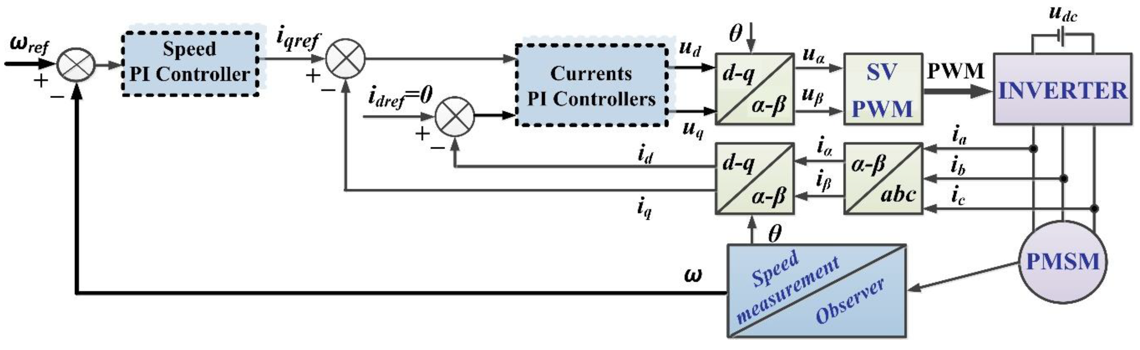
Figure 2.
Proposed PMSM control system using LADRC controller and ESO-type observer using RL-TD3 agent.
Figure 2.
Proposed PMSM control system using LADRC controller and ESO-type observer using RL-TD3 agent.
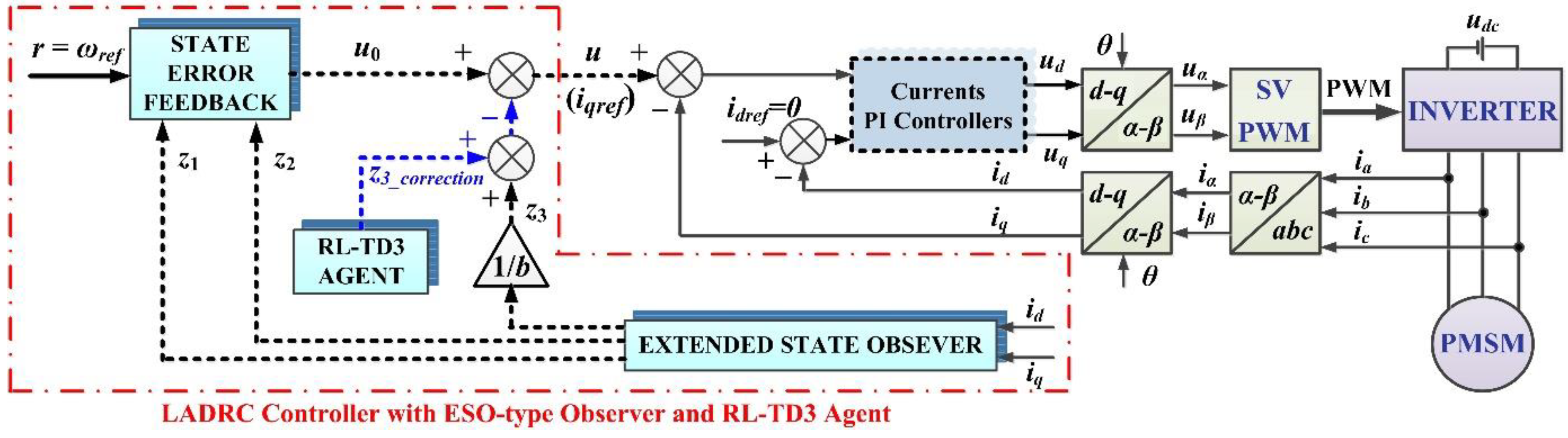
Figure 3.
Proposed PMSM control system using LADRC controller and DO-type observer using RL-TD3 agent.
Figure 3.
Proposed PMSM control system using LADRC controller and DO-type observer using RL-TD3 agent.
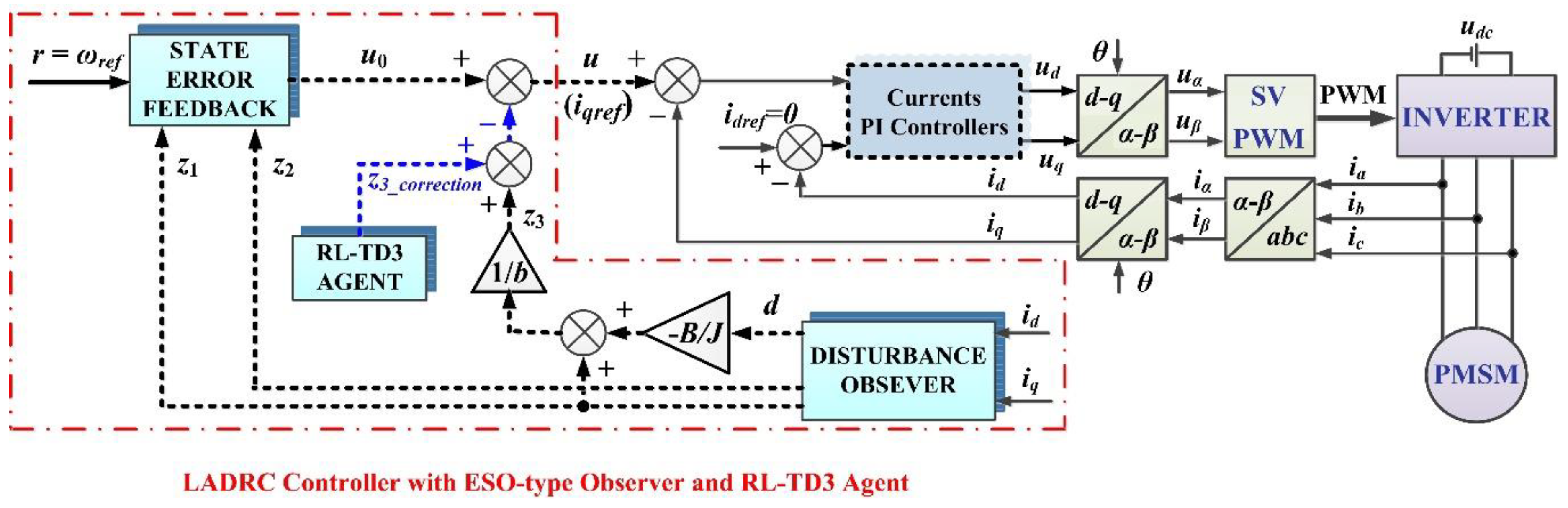
Figure 4.
LADRC-type control using ESO-type observer (third order) block diagram.
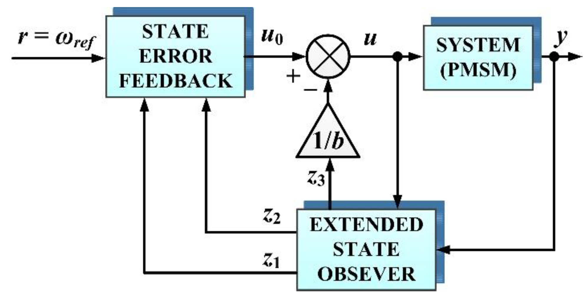
Figure 5.
ESO-type observer (third order) block diagram for rotor speed PMSM estimation.
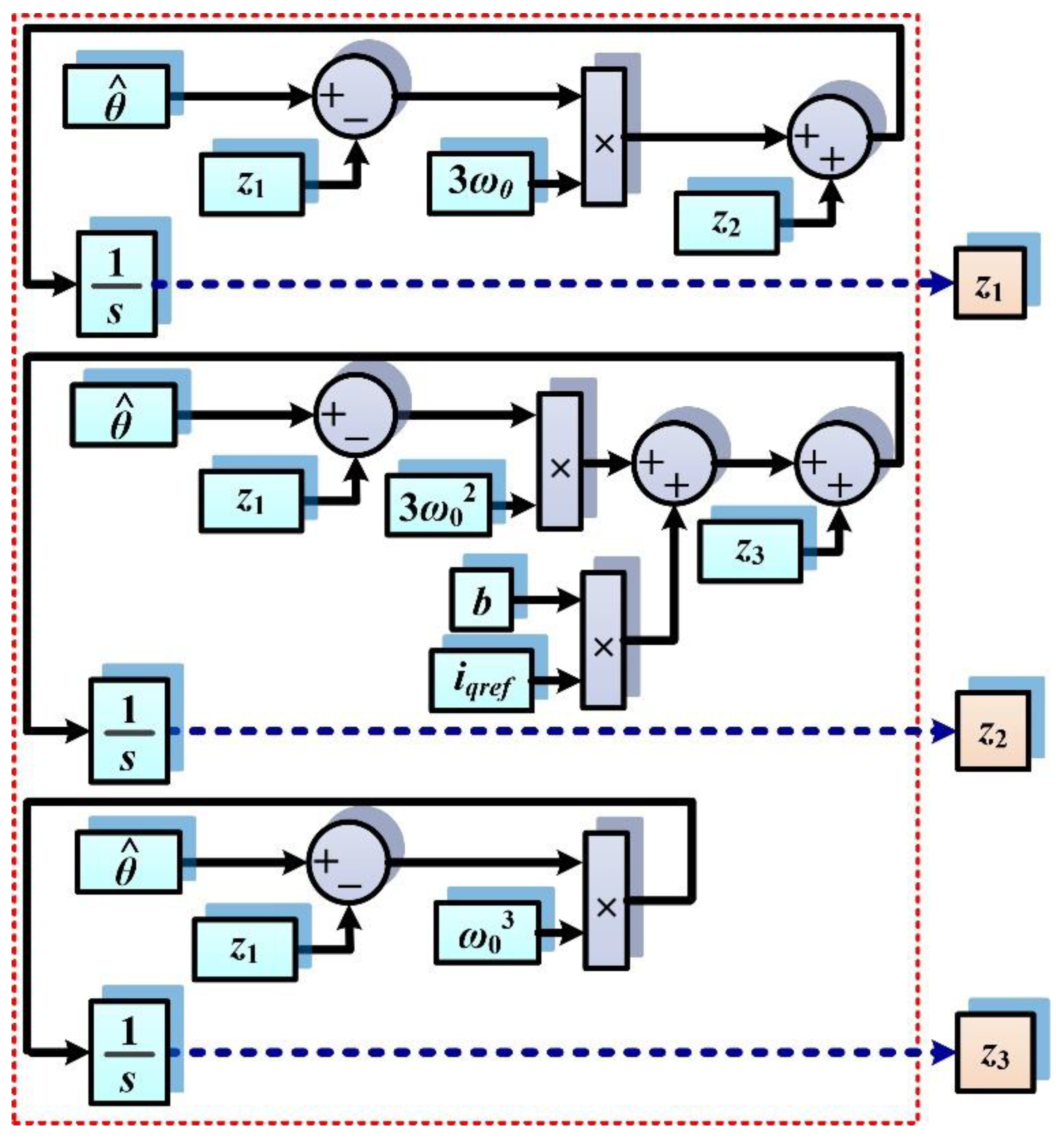
Figure 6.
LADRC-type PMSM speed control using ESO-type observer (second order) block diagram.
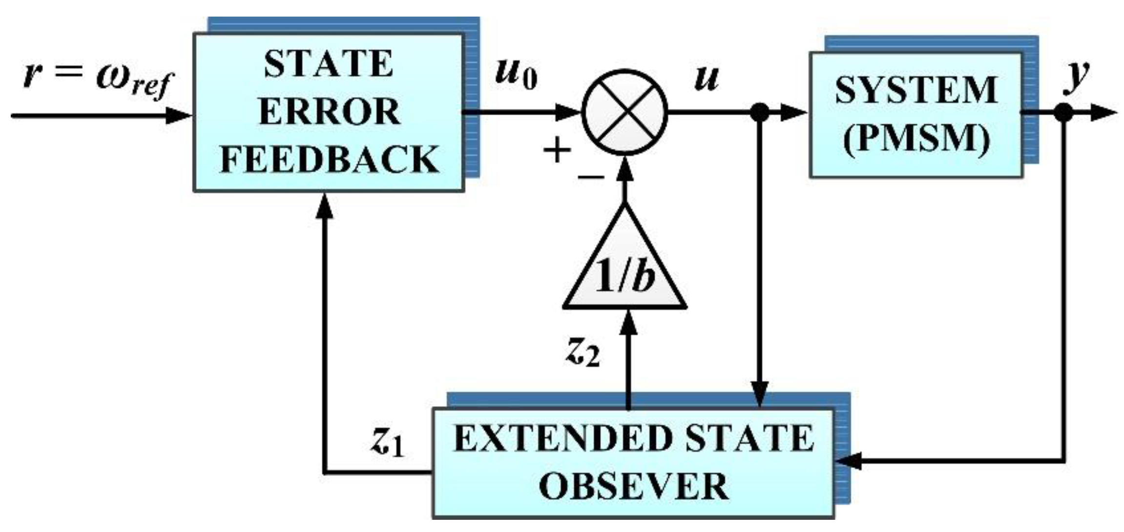
Figure 7.
ESO-type observer (second order) block diagram for rotor speed PMSM estimation.
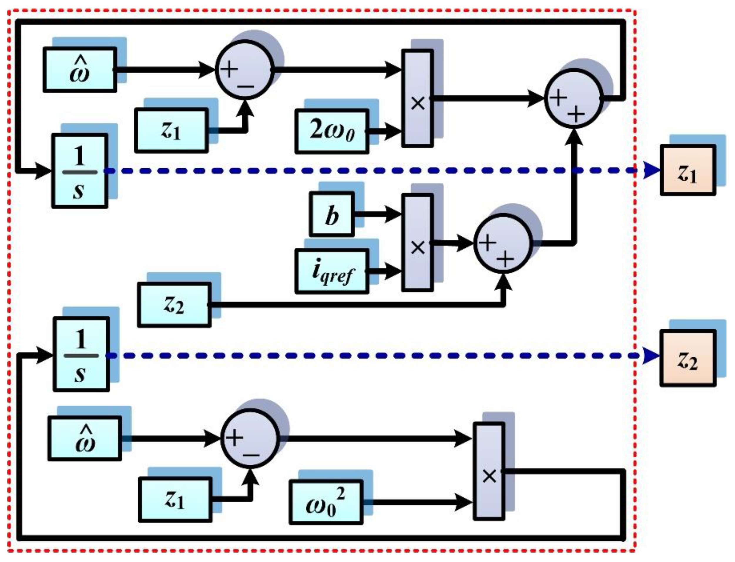
Figure 9.
DO-type observer block diagram.
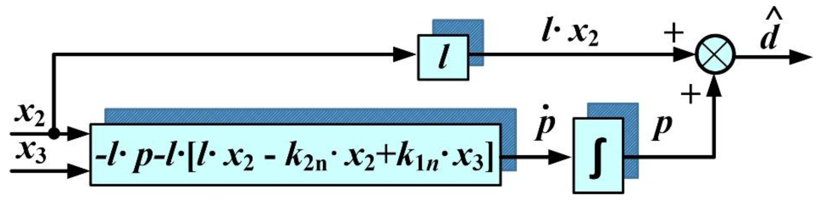
Figure 10.
DO-type observer block diagram for rotor speed PMSM estimation.
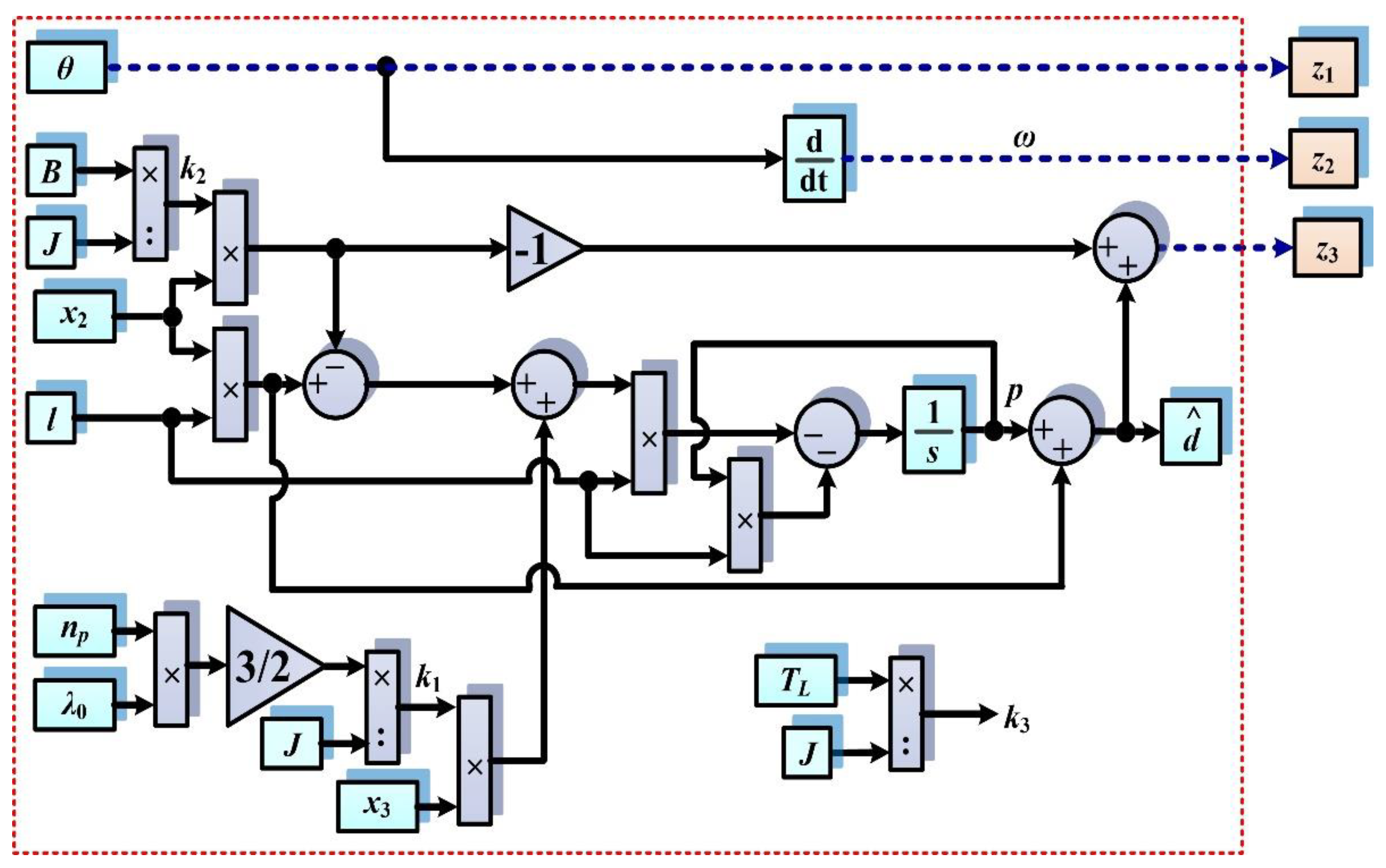
Figure 11.
LADRC-type PMSM speed control using DO-type observer block diagram.
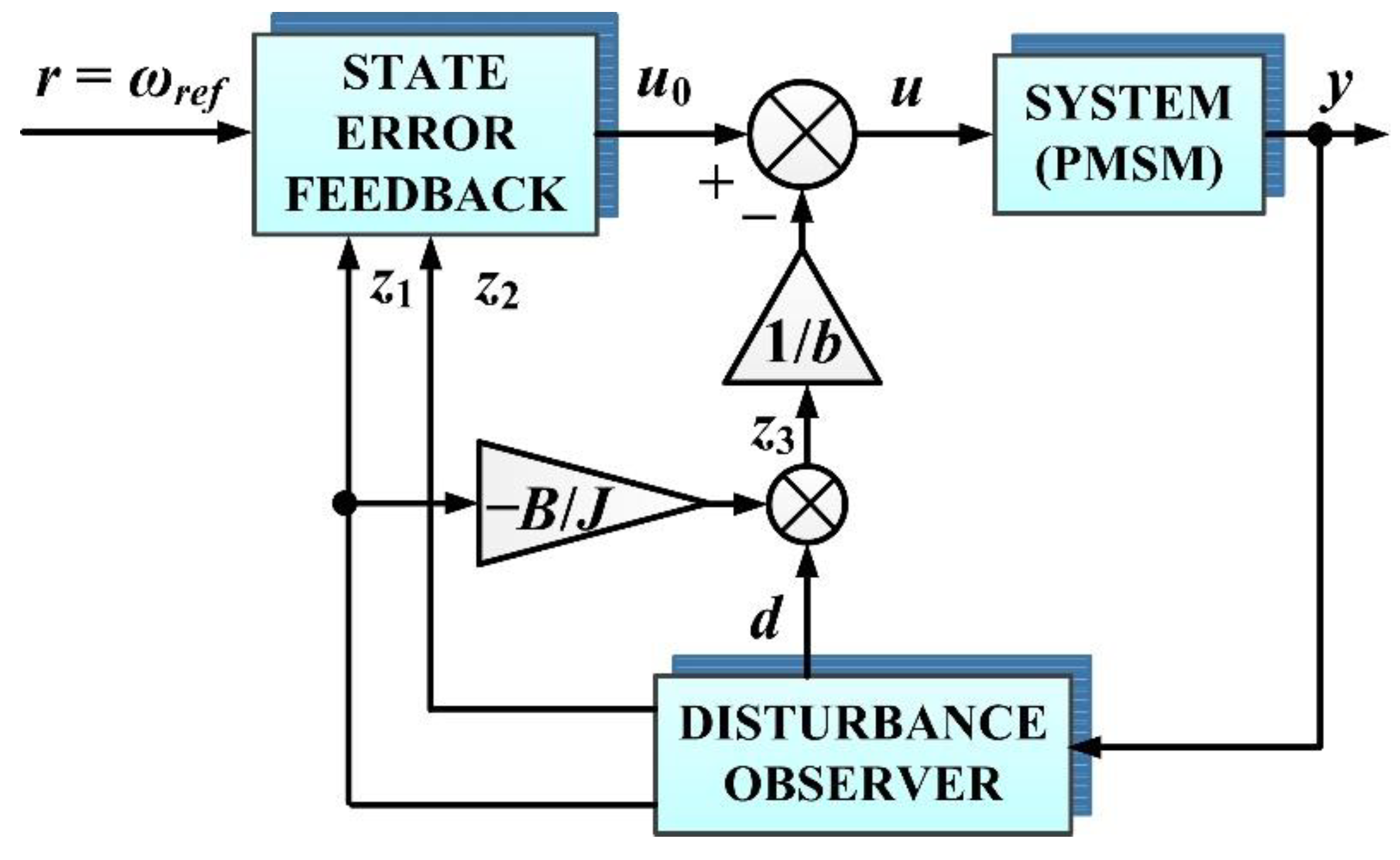
Figure 12.
Matlab/Simulink block diagram implementation for PMSM control based on LADRC controller and ESO-type observer.
Figure 12.
Matlab/Simulink block diagram implementation for PMSM control based on LADRC controller and ESO-type observer.
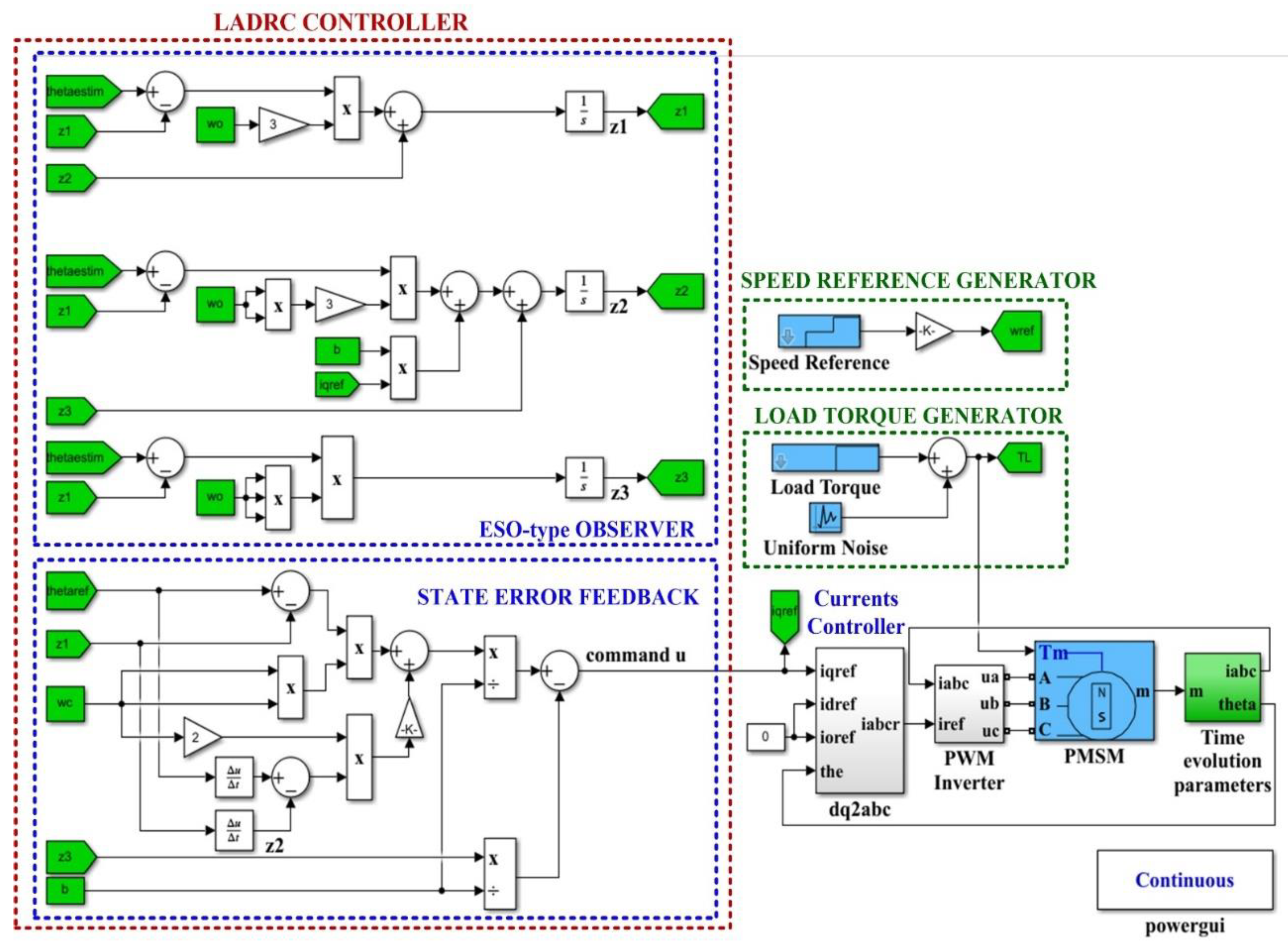
Figure 13.
Matlab/Simulink block diagram implementation for PMSM control based on LADRC controller and ESO-type observer using RL-TD3 agent.
Figure 13.
Matlab/Simulink block diagram implementation for PMSM control based on LADRC controller and ESO-type observer using RL-TD3 agent.
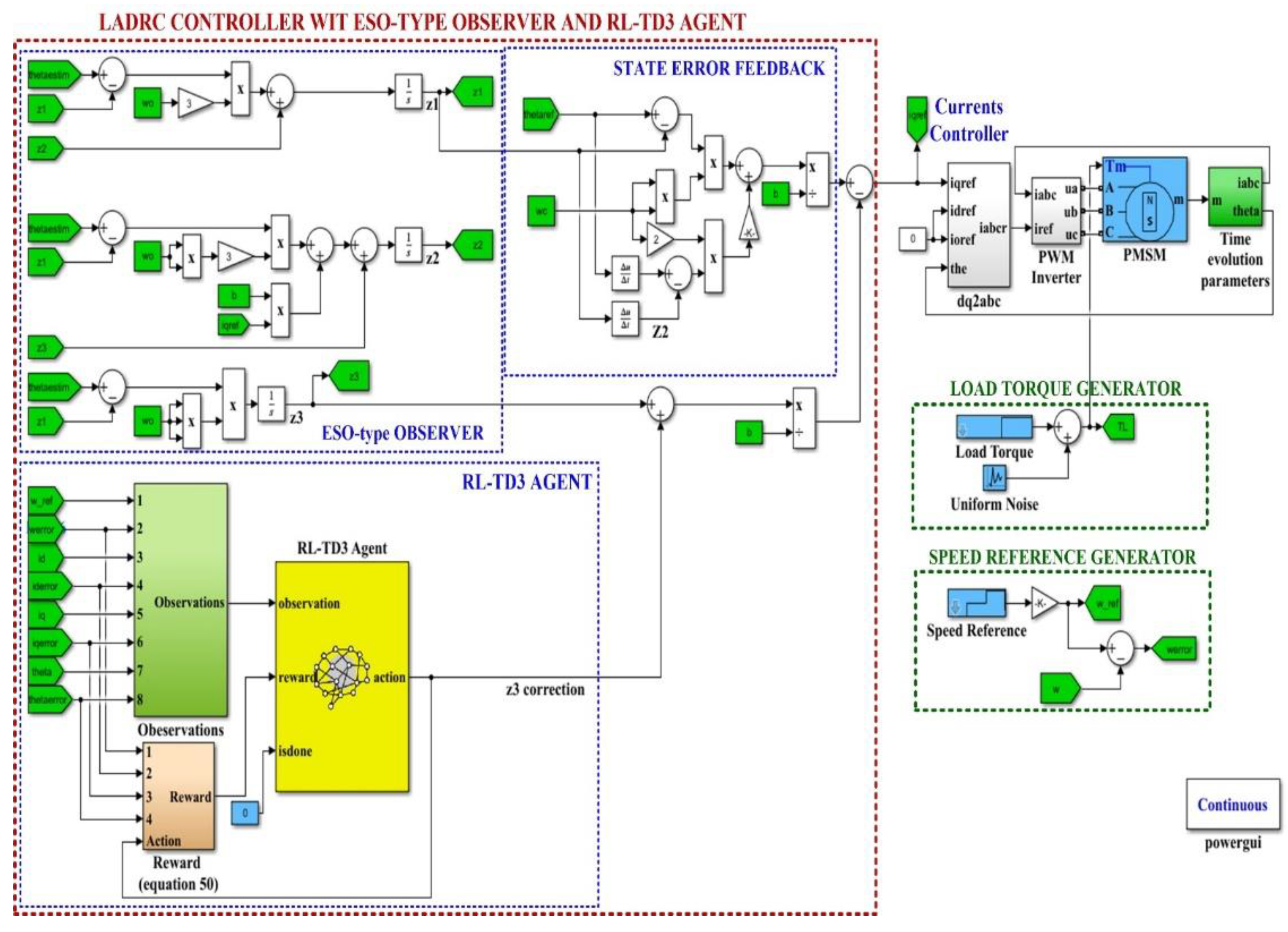
Figure 14.
Evolution of the performance for the RL-TD3-type agent for improvement of LADRC with ESO-type observer for PMSM control.
Figure 14.
Evolution of the performance for the RL-TD3-type agent for improvement of LADRC with ESO-type observer for PMSM control.
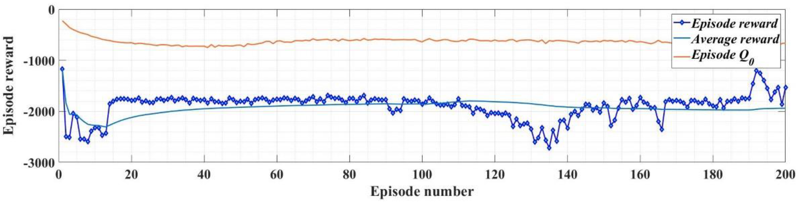
Figure 15.
Block diagram of Matlab/Simulink implementation for PMSM control based on LADRC controller and DO-type observer.
Figure 15.
Block diagram of Matlab/Simulink implementation for PMSM control based on LADRC controller and DO-type observer.
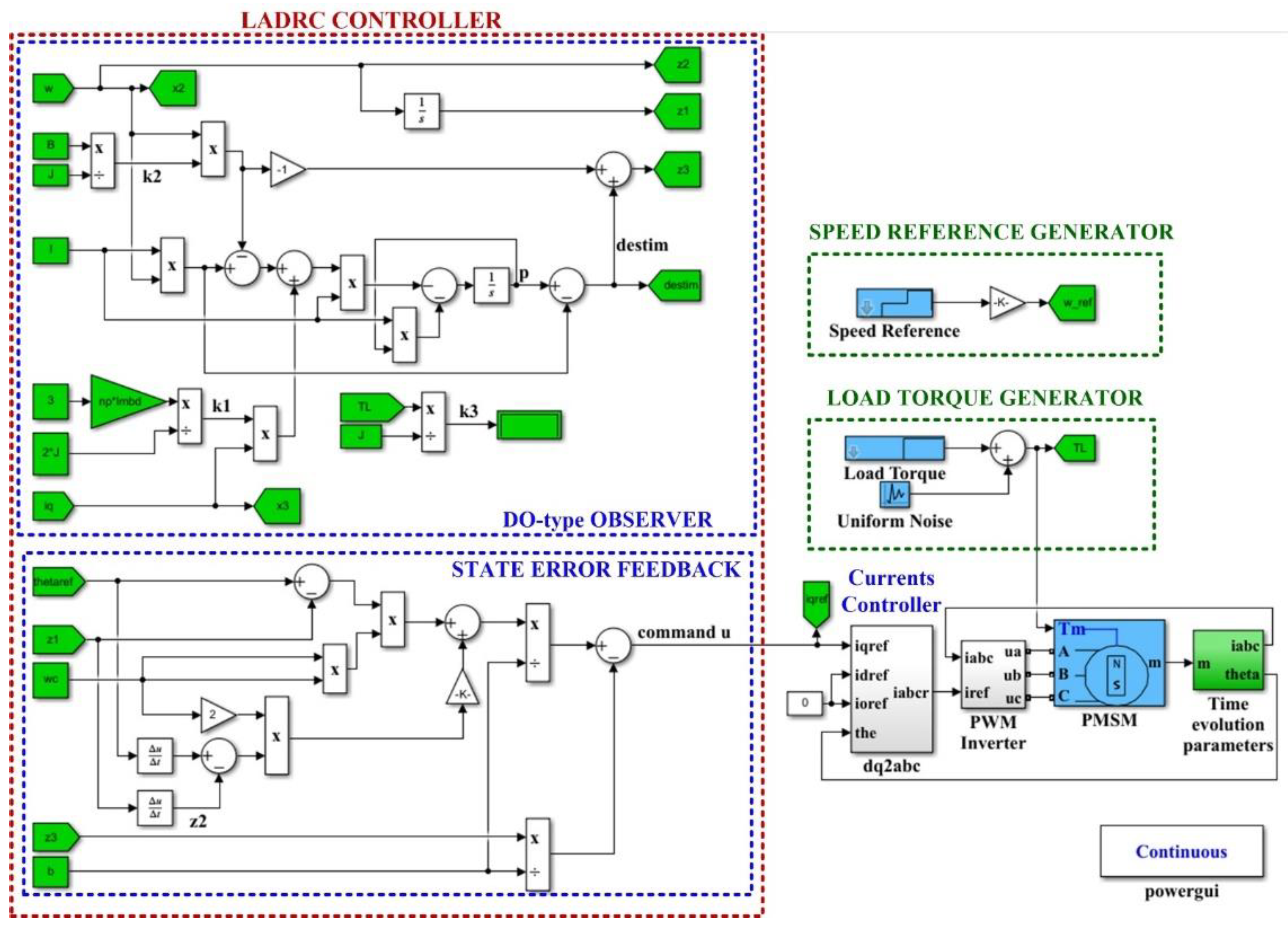
Figure 16.
Matlab/Simulink block diagram implementation for PMSM control based on LADRC controller and DO-type observer using RL-TD3 agent.
Figure 16.
Matlab/Simulink block diagram implementation for PMSM control based on LADRC controller and DO-type observer using RL-TD3 agent.
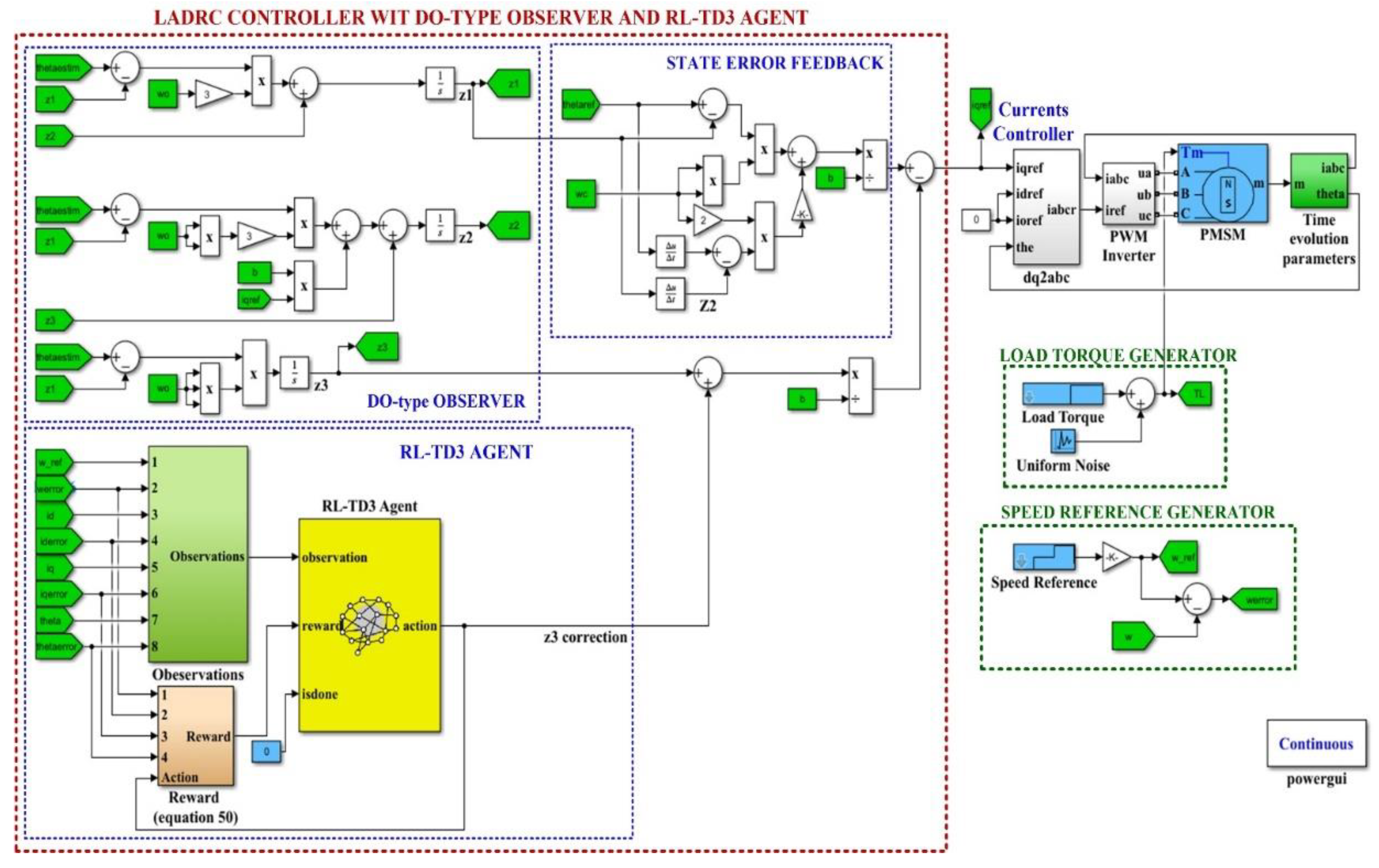
Figure 17.
Evolution of the performance for the RL-TD3-type agent for the improvement of LADRC with DO-type observer for PMSM control.
Figure 17.
Evolution of the performance for the RL-TD3-type agent for the improvement of LADRC with DO-type observer for PMSM control.
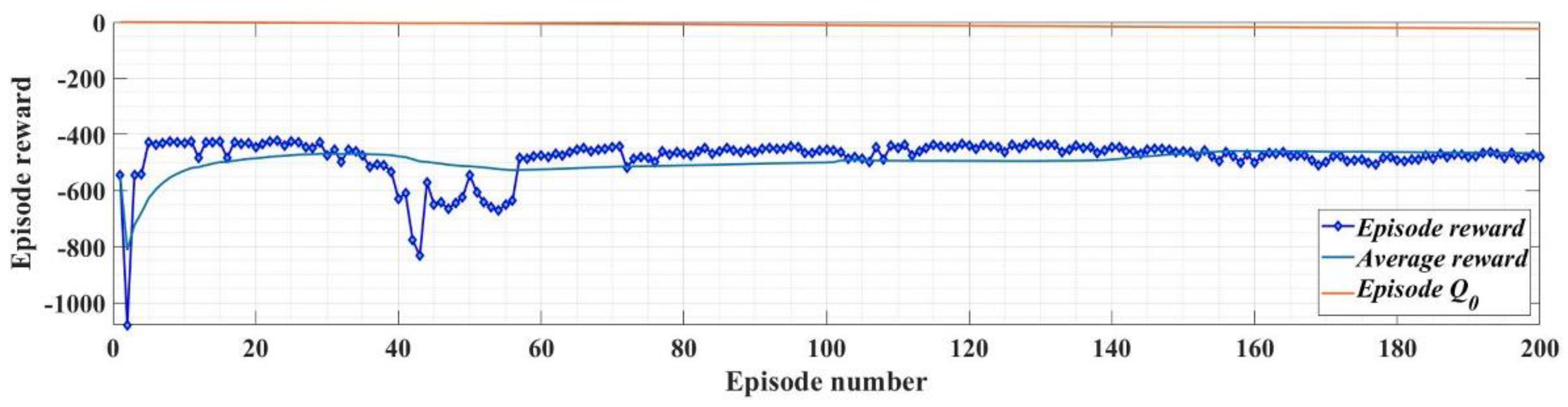
Figure 18.
Performance of the ACO-type algorithm for optimization of the DO-type observer gain.
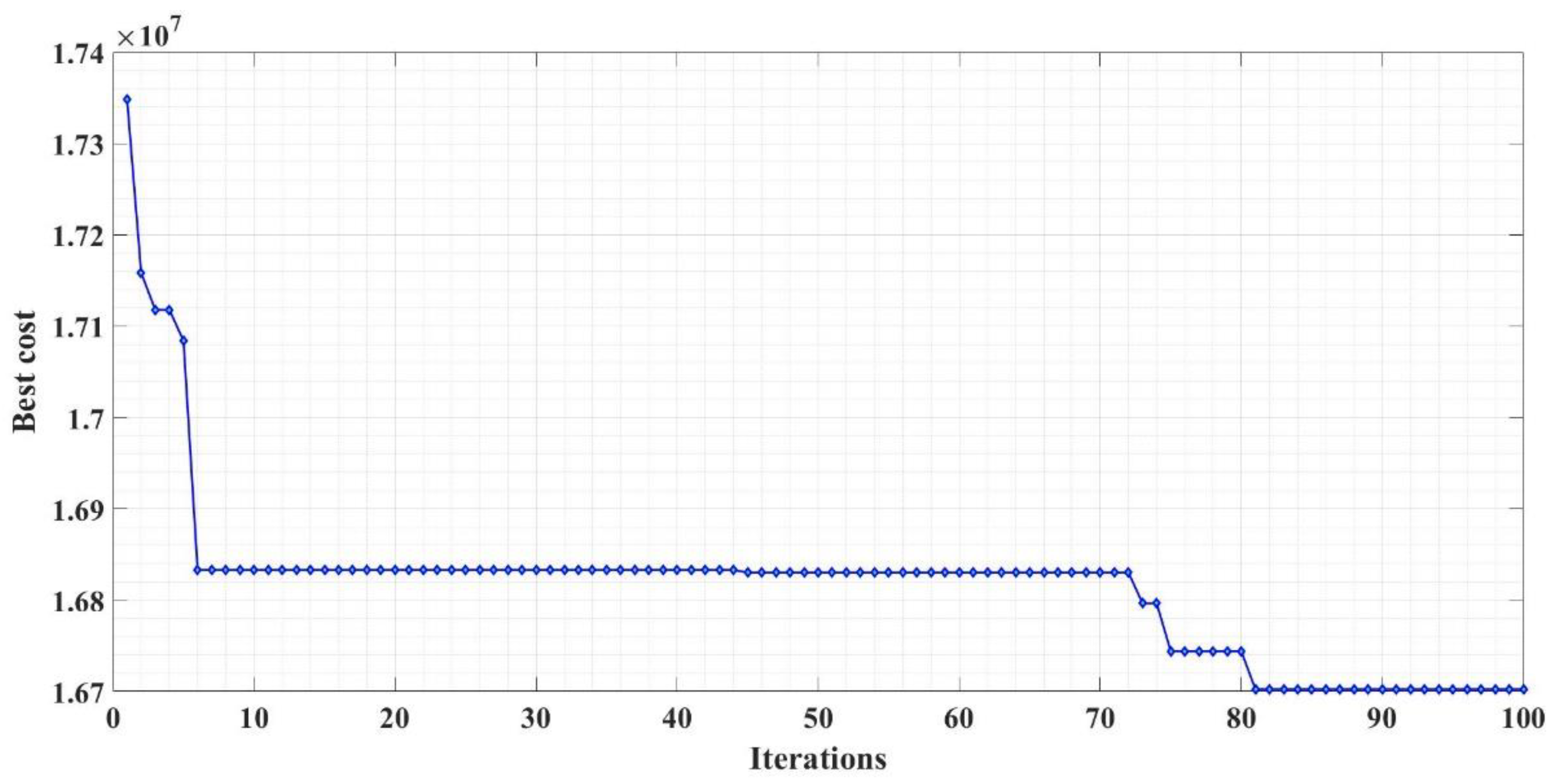
Figure 19.
PMSM control system based on PI speed controller versus PMSM control system based on LADRC controller with ESO-type observer (ωref = [1000 1200 1400 900]rpm and TL = 0.5Nm): (a) Parameters evolution of PMSM control system based on PI speed controller; (b) Parameters evolution of PMSM control system based on LADRC controller with ESO-type observer; (c) Speeds time evolution comparison for PI versus LADRC with ESO-type observer controllers of PMSM control system.
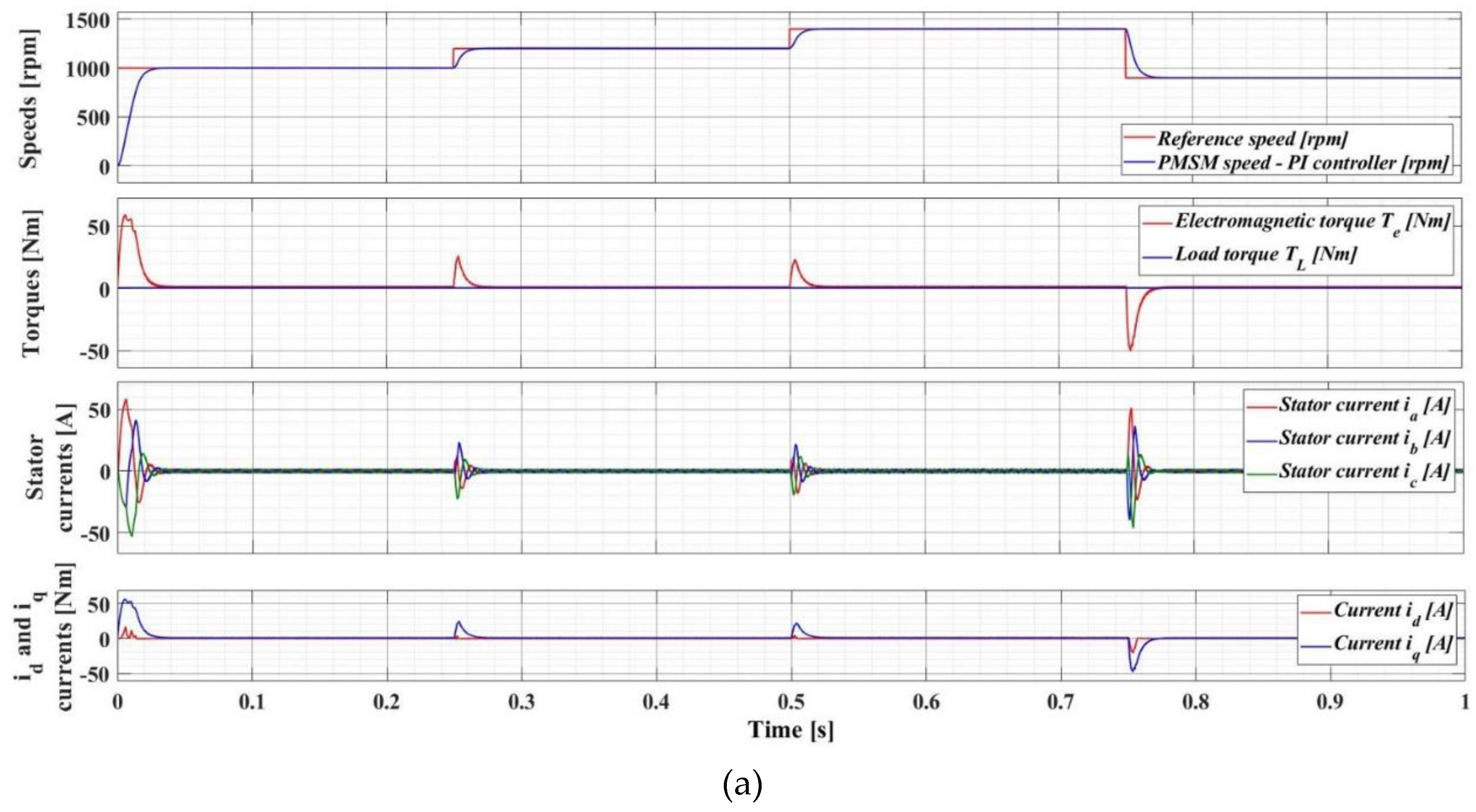
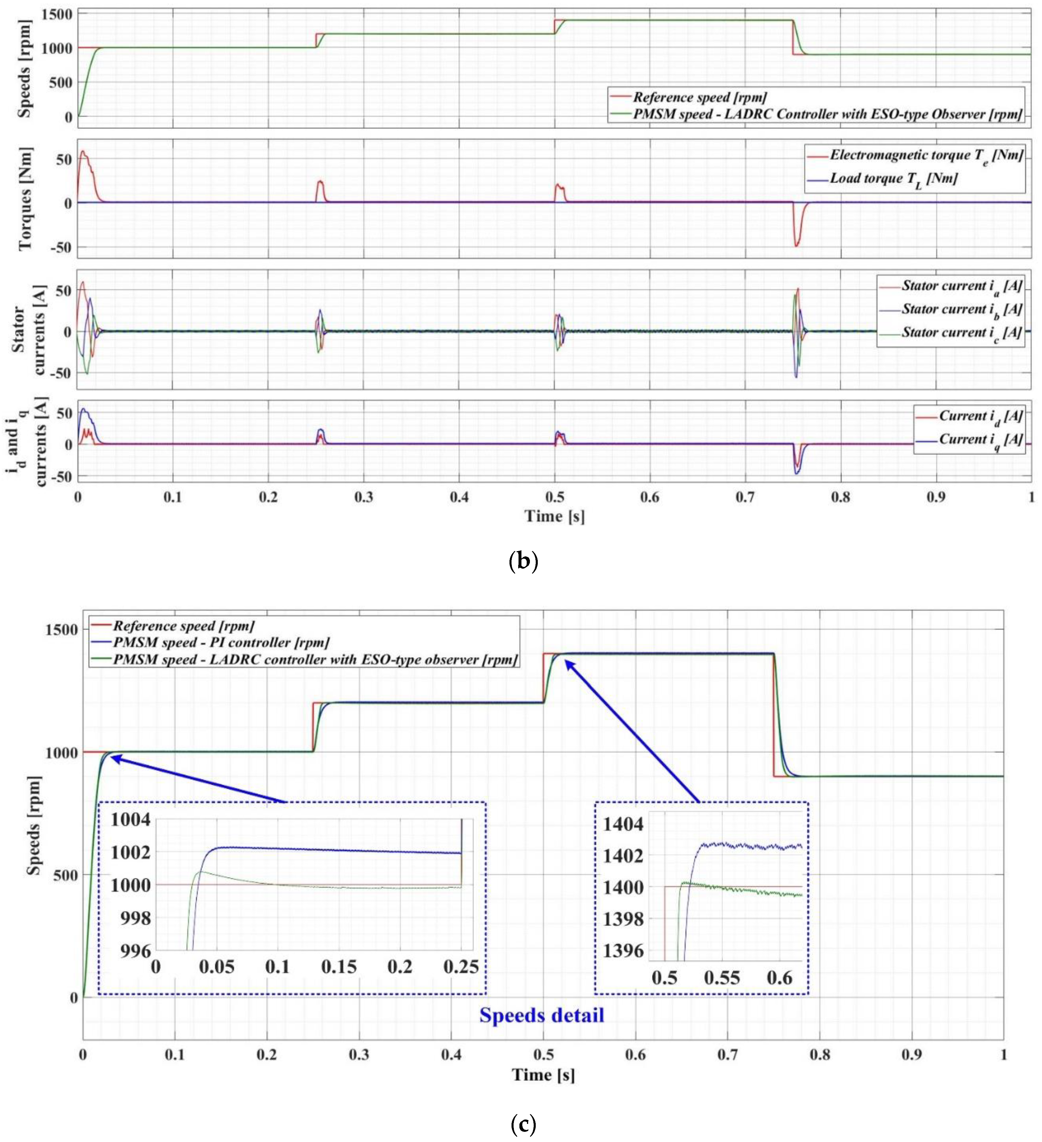
Figure 20.
Speeds time evolution comparison for PI versus LADRC with ESO-type observer controllers of PMSM control system (ωref = [1000 1200 1400 900]rpm and TL = 2Nm).
Figure 20.
Speeds time evolution comparison for PI versus LADRC with ESO-type observer controllers of PMSM control system (ωref = [1000 1200 1400 900]rpm and TL = 2Nm).
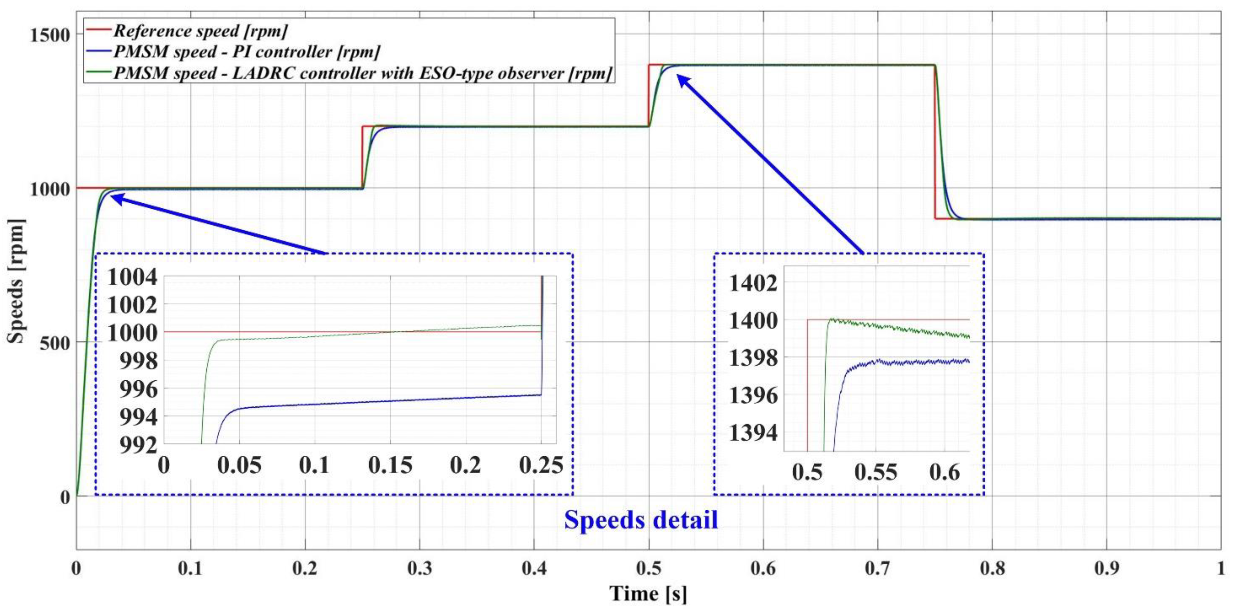
Figure 21.
Time evolution of PMSM control system parameters using LADRC controller with ESO-type observer (ωref = 1000rpm and TL = 4Nm).
Figure 21.
Time evolution of PMSM control system parameters using LADRC controller with ESO-type observer (ωref = 1000rpm and TL = 4Nm).
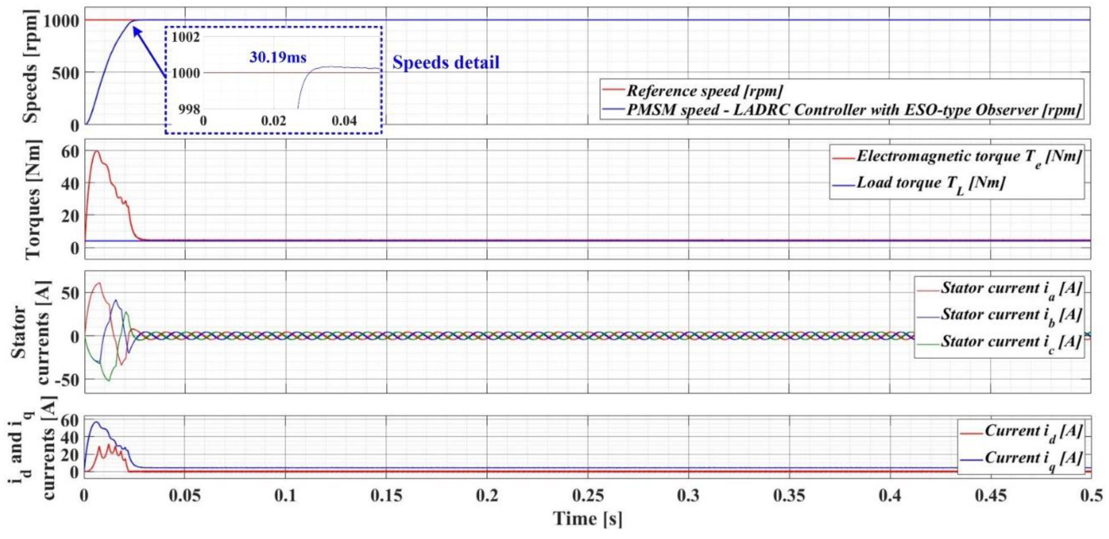
Figure 22.
Time evolution of PMSM control system parameters using LADRC controller with ESO-type observer (ωref = 1000rpm, TL = 4Nm with uniform distributed noise, and an increase of 100% for J parameter).
Figure 22.
Time evolution of PMSM control system parameters using LADRC controller with ESO-type observer (ωref = 1000rpm, TL = 4Nm with uniform distributed noise, and an increase of 100% for J parameter).
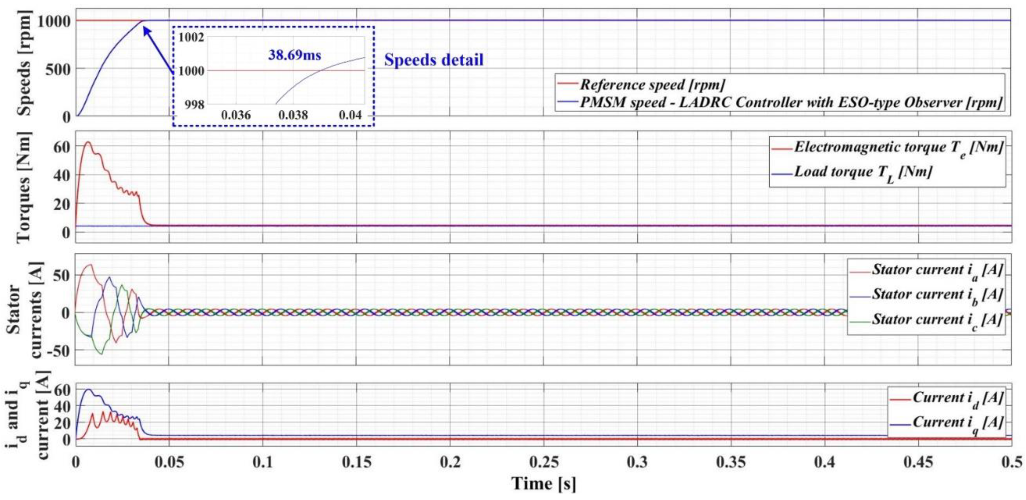
Figure 23.
Time evolution of PMSM control system parameters using LADRC controller with DO-type observer (ωref = 1000rpm and TL = 4Nm).
Figure 23.
Time evolution of PMSM control system parameters using LADRC controller with DO-type observer (ωref = 1000rpm and TL = 4Nm).
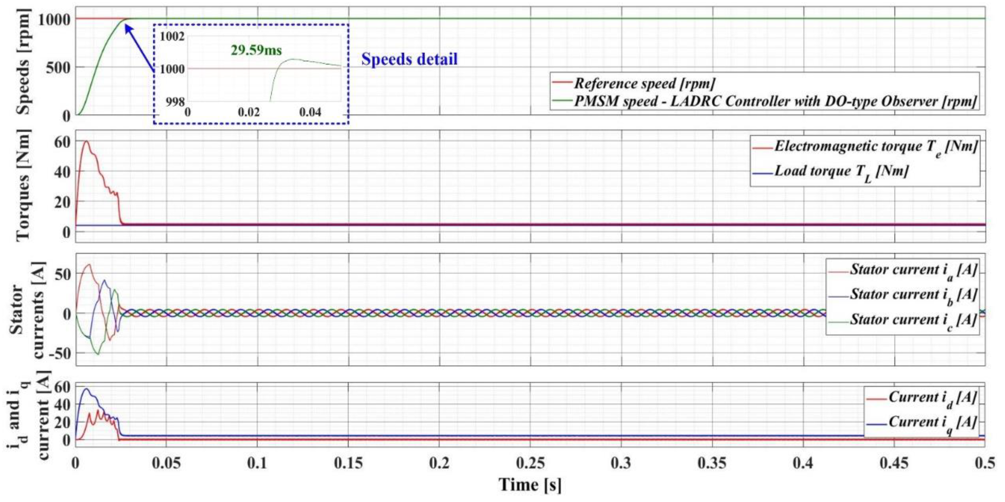
Figure 24.
Time evolution of PMSM control system parameters using LADRC controller with ESO-type observer and RL-TD3 agent (ωref = 1000rpm and TL = 4Nm).
Figure 24.
Time evolution of PMSM control system parameters using LADRC controller with ESO-type observer and RL-TD3 agent (ωref = 1000rpm and TL = 4Nm).
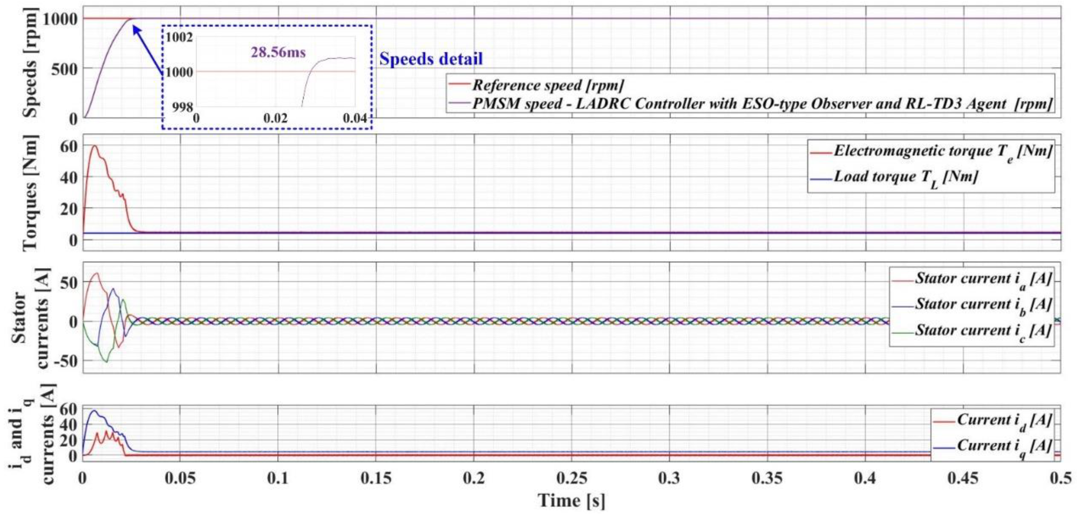
Figure 25.
Time evolution of PMSM control system parameters using LADRC controller with DO-type observer and RL-TD3 agent (ωref = 1000rpm and TL = 4Nm).
Figure 25.
Time evolution of PMSM control system parameters using LADRC controller with DO-type observer and RL-TD3 agent (ωref = 1000rpm and TL = 4Nm).
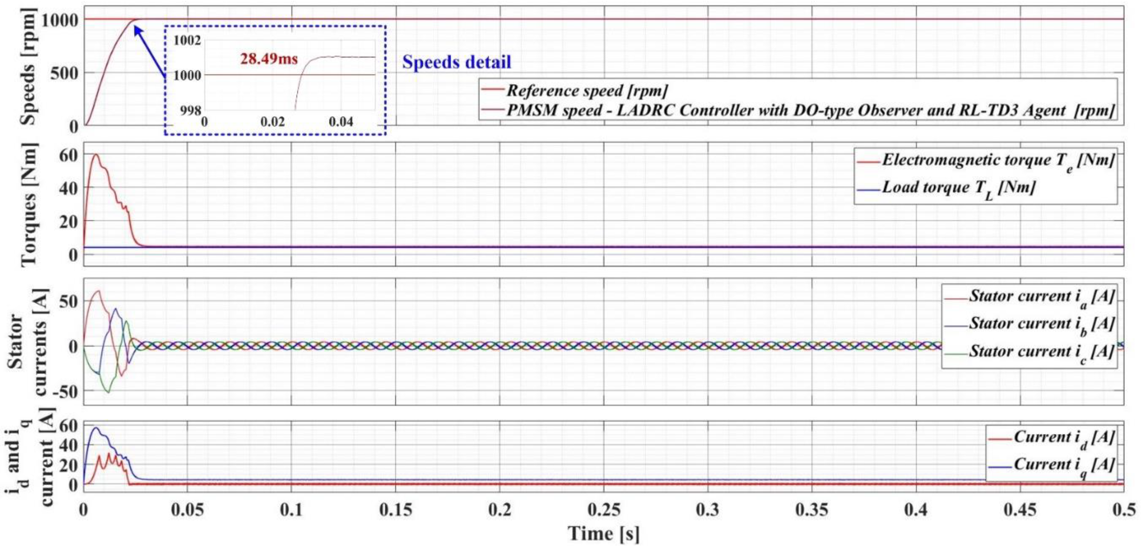
Figure 26.
Speeds evolution comparison for proposed control systems for PMSM based on LADRC controller with ESO/DO type observer and RL-TD3 agent.
Figure 26.
Speeds evolution comparison for proposed control systems for PMSM based on LADRC controller with ESO/DO type observer and RL-TD3 agent.
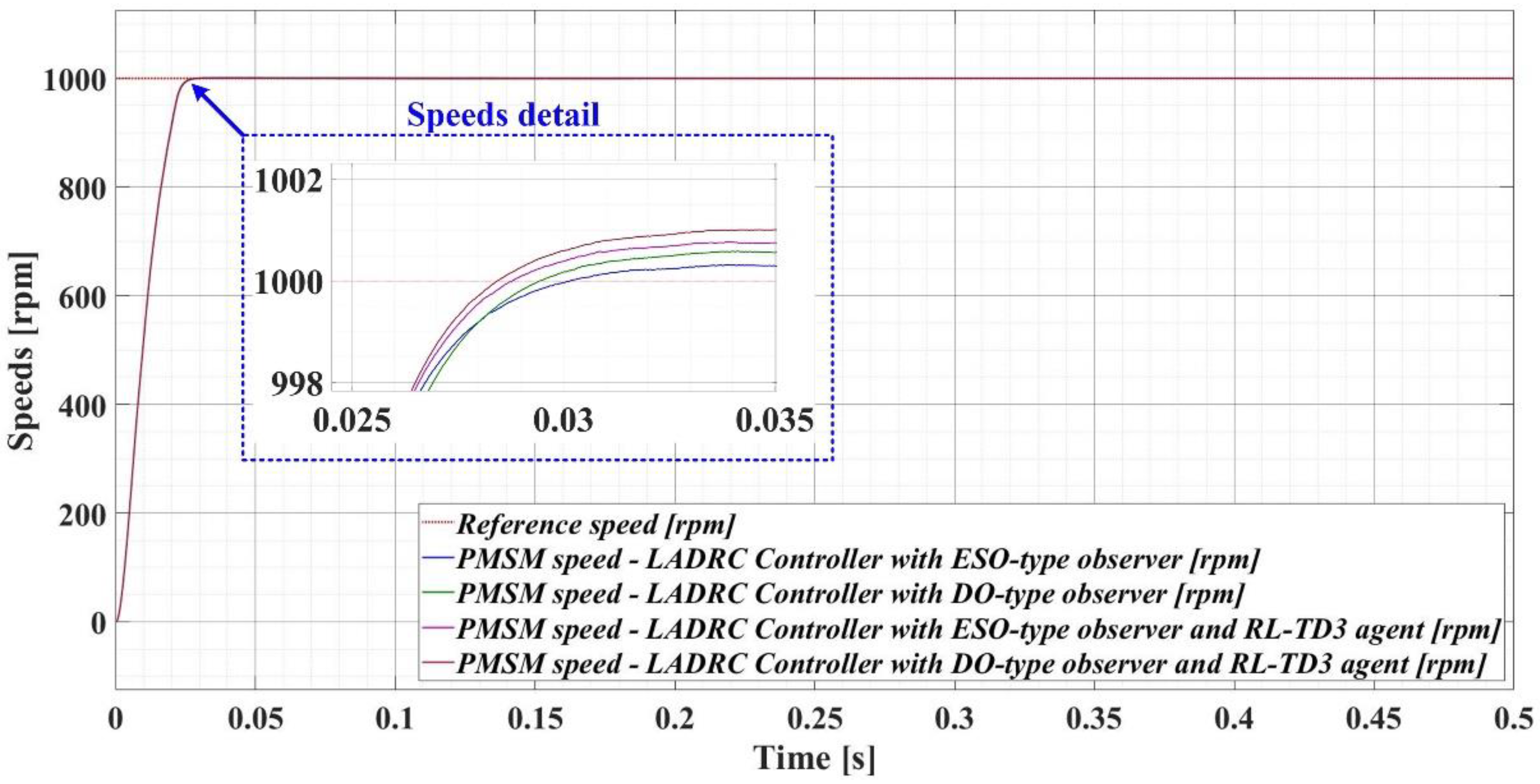
Figure 27.
Graphical representation for DF of speed signal – PMSM control system based on LADRC controller with ESO-type observer.
Figure 27.
Graphical representation for DF of speed signal – PMSM control system based on LADRC controller with ESO-type observer.

Figure 28.
Graphical representation for DF of speed signal – PMSM control system based on LADRC controller with DO-type observer.
Figure 28.
Graphical representation for DF of speed signal – PMSM control system based on LADRC controller with DO-type observer.
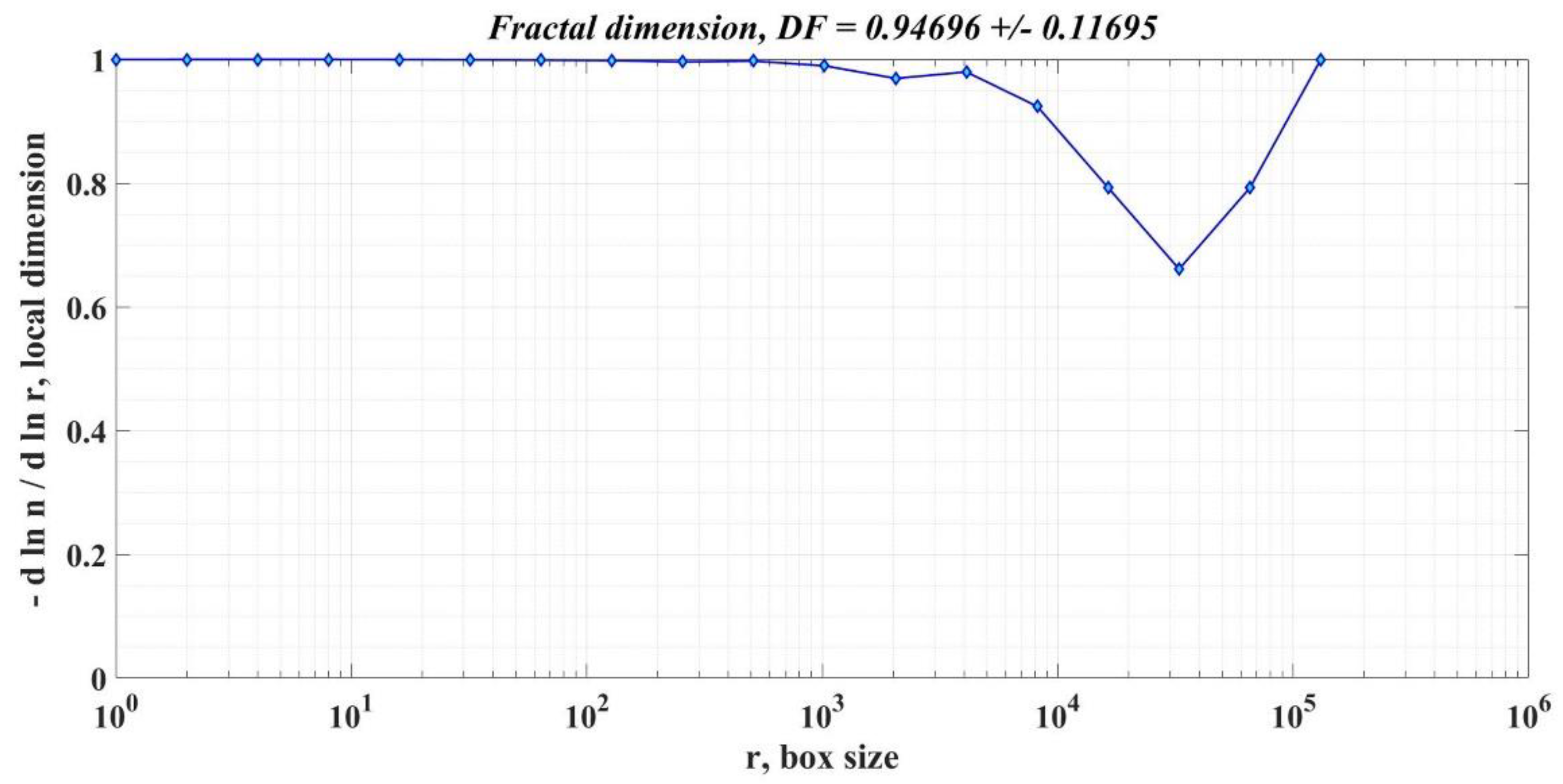
Figure 29.
Graphical representation for DF of speed signal – PMSM control system based on LADRC controller with ESO-type observer and RL-TD3 agent.
Figure 29.
Graphical representation for DF of speed signal – PMSM control system based on LADRC controller with ESO-type observer and RL-TD3 agent.
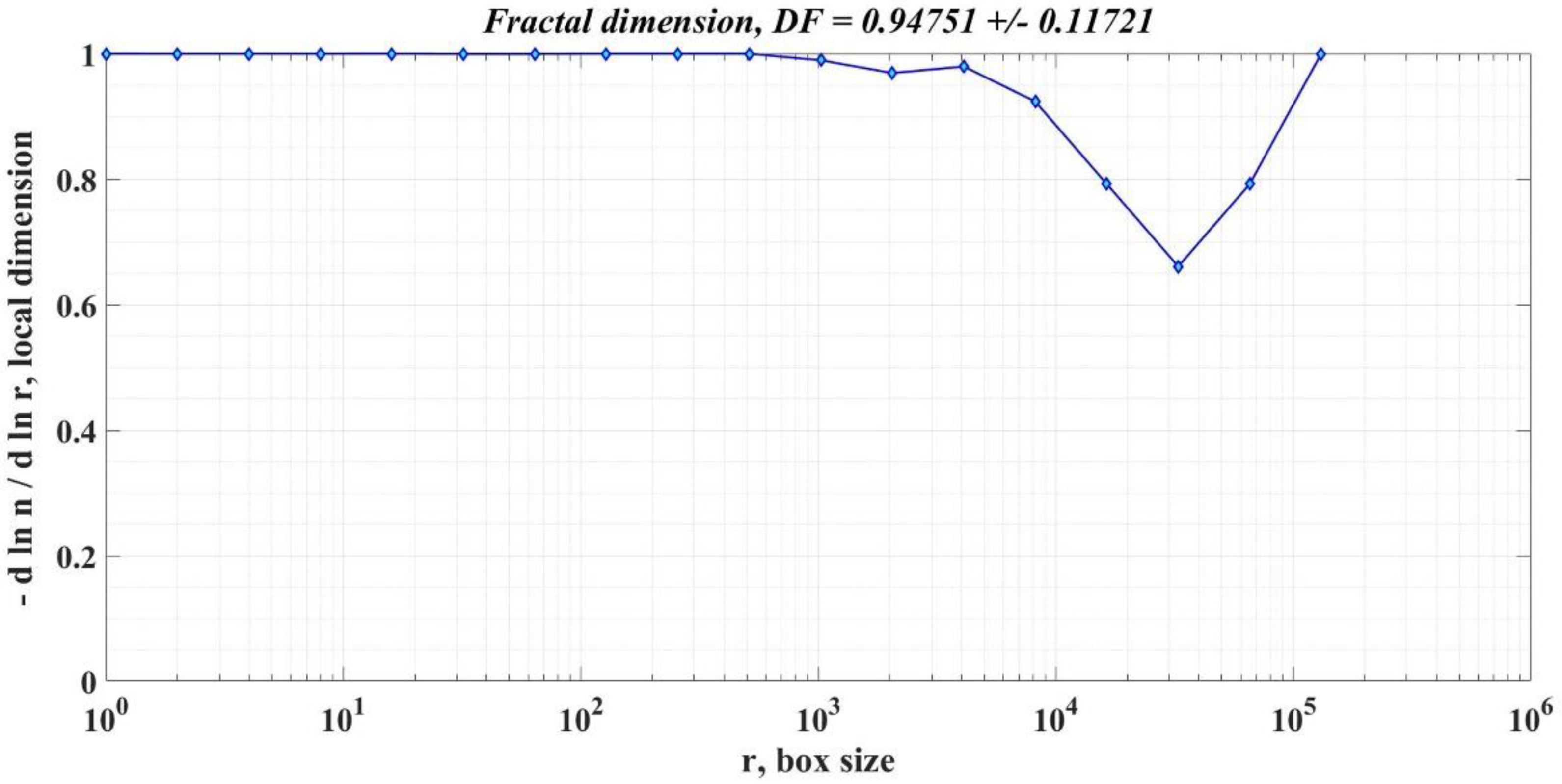
Figure 30.
Graphical representation for DF of speed signal – PMSM control system based on LADRC controller with DO-type observer and RL-TD3 agent.
Figure 30.
Graphical representation for DF of speed signal – PMSM control system based on LADRC controller with DO-type observer and RL-TD3 agent.


Table 1.
PMSM nominal parameters used in numerical simulation.
| Parameter | Value | Unit |
|---|---|---|
| Stator resistance - Rs | 2.875 | Ω |
| Inductances on d-q rotating reference frame – Ld and Lq | 0.0085 | H |
| Combined inertia of rotor and load - J | 0.008 | kg·m2 |
| Combined viscous friction of rotor and load - B | 0.005 | N·m·s/rad |
| Flux induced by the permanent magnets of the rotor in the stator phases - λ0 | 0.175 | Wb |
| PMSM Pole pairs number - nP | 4 | - |
Table 2.
Performances of proposed controllers for PMSM sensored control system.
| Controller type for PMSM speed control | Response time [ms] |
Rotor speed ripple [rpm] |
DF of PMSM rotor speed signal |
|---|---|---|---|
| LADRC Controller with ESO-type Observer | 30.19 | 119.79 | 0.94588 +/– 0.11768 |
| LADRC Controller with DO-type Observer | 29.59 | 118.56 | 0.94696 +/– 0.16951 |
| LADRC Controller with ESO-type Observer and RL-TD3 Agent | 28.56 | 117.42 | 0.94751 +/– 0.11721 |
| LADRC Controller with DO-type Observer and RL-TD3 Agent | 28.49 | 116.38 | 0.94827 +/– 0.11746 |
Disclaimer/Publisher’s Note: The statements, opinions and data contained in all publications are solely those of the individual author(s) and contributor(s) and not of MDPI and/or the editor(s). MDPI and/or the editor(s) disclaim responsibility for any injury to people or property resulting from any ideas, methods, instructions or products referred to in the content. |
© 2023 by the authors. Licensee MDPI, Basel, Switzerland. This article is an open access article distributed under the terms and conditions of the Creative Commons Attribution (CC BY) license (http://creativecommons.org/licenses/by/4.0/).
Copyright: This open access article is published under a Creative Commons CC BY 4.0 license, which permit the free download, distribution, and reuse, provided that the author and preprint are cited in any reuse.


