1. Introduction
3D scene perception without wearing glasses can offer convenience, hence glasses-free 3D display has attracted great attention in recent years. Substantial researches have been conducted to realize glasses-free 3D display [
1,
2,
3], among which, conventional autostereoscopic display simply sends parallax images to viewer’s eyes. The technique of autostereoscopic is now quite mature, but the simple principle determines that the 3D impression is not natural because of the vergence-accommodation conflict [
4,
5]. Light field display is another kind of glasses-free 3D display which can optically redistribute the spatial information of 3D scene. Since the scene is reconstructed by the light field, a clear 3D scene with correct geometric occlusion and smooth motion parallax can be observed by the viewer.
Light field display can be realized with various methods [
6,
7,
8,
9,
10,
11,
12,
13,
14,
15,
16], among which multi-projection scheme is a common technique [
17,
18]. Smooth motion parallax and high definition can be achieved with high dense projectors, but considerable calibration efforts and complex system arrangement present technique difficulties. It is also a giant challenge to handle the massive data and control all projectors synchronously. Compressive light field display (or multi-layer tensor display) which consists of multiple liquid crystal displays (LCDs) is another 3D display technology [
19,
20]. The compact structure is among the advantages of compressive light field display, but low brightness caused by multiple LCDs degrade the quality of 3D images. Besides, massive complex calculations are required to decompose the target light field information loaded on multiple LCDs. Integral display which is the inverse process of integral photography can provide natural 3D scene with full color and full parallax by optically reconstructing light field of 3D scene [
21,
22]. In addition, the structure of integral display which mainly includes an LCD panel and a lens array is comparatively simple, while the low resolution and massive data are the difficult issues to tackle. Multi-view display can be considered as a super multi-view (SMV) light field display if the viewpoints are dense enough [
23]. The optical structure of integral display and SMV are similar despite the pixel arrangement in the image source are different. SMV light field display generates dense viewpoints at the optimal viewing distance (OVD) to provide smooth motion parallax, while the large number of viewpoints normally lead to massive data and low definition of 3D images.
All light field displays mentioned above can offer 3D scene in a relatively wide range, and numerous studies have concentrated on the effort to achieve the widest possible viewing angle. Space-multiplexing technique is introduced to realize a 90-degree viewing angle [
24], and a 120-degree perception is achieved by time-multiplexing technique [
25]. A tabletop light field display with FOV of 70°x70 is also achieved [
26]. The simultaneous wide viewing angle will require massive information. Besides, the wide viewing angle is at the cost of the reduced resolution. In the flat-panel (such as LCDs or LEDs) based light field display, the pixels of the flat-panel are converted to the angular and spatial information for 3D images. Since the total space bandwidth product of the flat-panel are limited, large angular display in a wide range means that few pixels are converted to designated direction, giving rise to low definition of 3D images.
Wide viewing angle can provide 3D images for multi-viewer simultaneously, while a single viewer needs to view the display in a specific viewing position. Eye-tracking is another technique normally applied to a single user. While Lens array with a long focal length is applied to enhance the depth range of integral display, eye-tracking can be further introduced to widen the viewing range [
27,
28]. For this purpose, Ueno presented a SMV near-eye display system based on a high-speed spatial light modulator with a 2D light source array [
29], 21 viewpoints with the density of 0.5 mm
-1 was achieved with time-multiplexing technique. Takaki demonstrated a SMV display with low resolution flat-panel [
30], which could provide 3D images with viewpoints density of 0.38 mm
-1 by providing only four viewpoints to each eye. However, the scheme decreases the horizontal width of the observation area and the high crosstalk further deteriorates the display quality. Yang developed a crosstalk-suppressed dense multi-view light field display with micro-pinhole array [
31], which could exhibit the 3D images with viewpoints density of 0.75 mm
-1 and the crosstalk of less than 7%. However, the applying of micro-pinhole array sacrifices the brightness of 3D images. Wang demonstrated a low-crosstalk SMV light field display with the vertically-collimated programmable directional backlight, dense up to 1 mm
-1 viewpoints were generated to provide natural depth cues and smooth motion parallax [
32]. Nevertheless, the dense viewpoints were generated with a vertical diffuser, which blurs the 3D images.
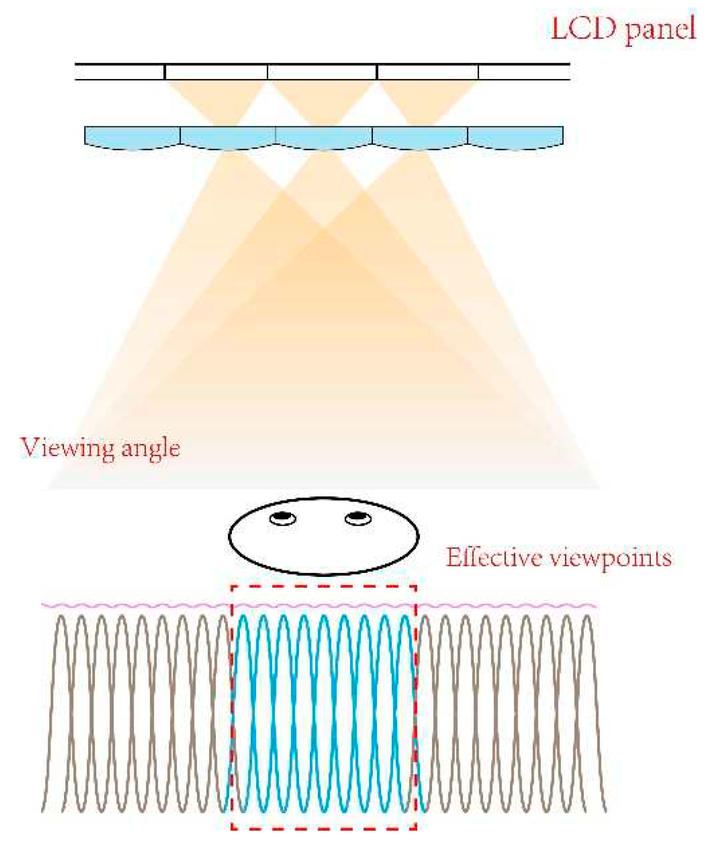
Figure 1.
The effective viewpoints for a single viewer in conventional light field display.
Figure 1.
The effective viewpoints for a single viewer in conventional light field display.
Here, a SMV light field display is proposed to compress the information in the viewing zone of a single user to alleviate the information redundancy by reducing the redundant viewpoints. A quasi-directional backlight is proposed and a lenticular lens array (LLA) with a long focal length is applied to specify the viewing zone. With the quasi-directional backlight and the LLA, the image transmission is consistent with the illumination direction. 17 viewpoints with the density of 0.13 mm-1 are generated in a 5-degree range to ensure smooth motion parallax. Compared with the previous SMV light field display mentioned above, such a viewpoint density simultaneously reduces redundant information and ensures parallax saltation-free. Since the viewpoints are concentrated in the viewing zone of a single viewer, the viewing area is practically decreased. Eye-tracking technique is then introduced to extend the total observation range. By acquiring the position of the viewer in real-time, accommodating the LCD image and switching the directional backlight synchronously, vivid 3D images can be sent to the viewer retina precisely. The total viewing space is extended to 30-degree.
With this configuration, the information utilization rate and the energy efficiency are improved substantially. Besides, the reserved small quantity of viewpoints reduces the requirements of information transmission bandwidth, hence providing a real-time render and display of light field information.
2. Principle
2.1. System configuration
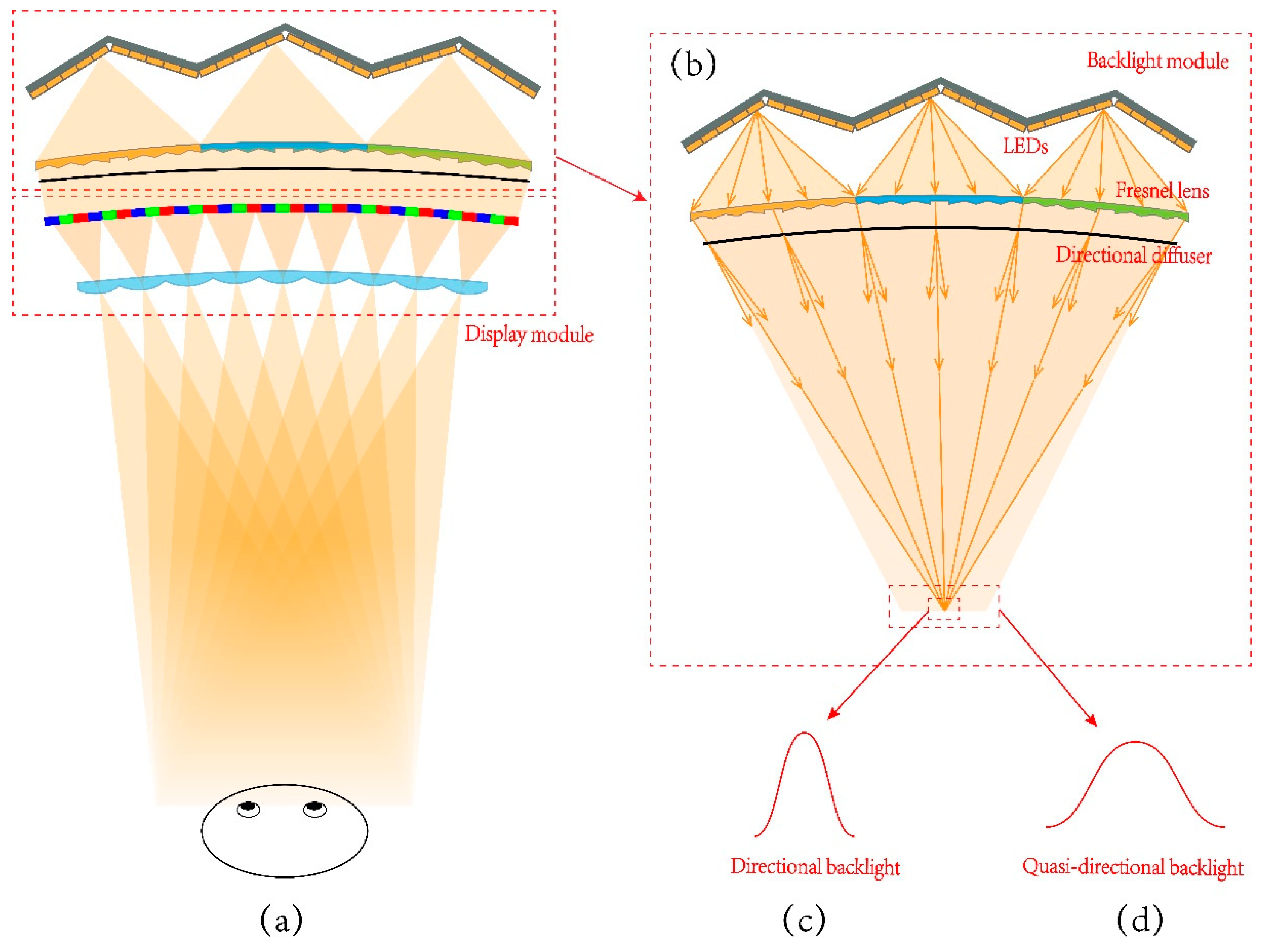
The proposed light field display contains the quasi-directional backlight module and the display module, as shown in
Figure 2a. The quasi-directional backlight module is shown in
Figure 2b, which consists of several units arranged side by side and distributed on a circular arc [
33]. Each unit in the backlight module comprises a linear Fresnel lens (LFL) and a series of LEDs. The LEDs are arranged in a V-shape to fit the field curvature of LFL. In addition, a directional diffuser is utilized to achieve small angle diffusion in horizontal direction. A 31.5-inch curved LCD panel with curvature radius at 1451 mm and with a resolution of 3840x2160 is adopted in the proposed light field display to load the encoded light field information. The LLA is placed in front of the curved LCD panel to control the light rays and generate viewpoints. With the LLA, the light field information loaded on the LCD can be decoded and the viewpoints can be generated at the OVD (1451 mm away from the system). To ensure that the viewpoints can be generated precisely, the quasi-directional backlight, the curved LCD panel and the LLA are placed on three concentric circles. In addition, eye-tracking technique is further introduced to provide directional illumination for extended viewing area.
The quasi-directional backlight module is utilized as the illumination light source. The divergent light rays emitting from LEDs are collected and converged to the convergent light rays with well-defined direction by the LFL. By introducing the directional diffuser, the convergent light rays will diverge in horizontal direction with a small angle. Although the directional information is interrupted by the diffuser, the degree of divergent in horizontal direction is small to retain its directional property. After passing through the LCD, the encoded light field information loaded on the LCD is carried by the light rays. The LLA is placed in front of the curved LCD panel to collect the light rays with light field information and generate viewpoints at the OVD. With the LLA, the viewpoints are concentrated in a small viewing zone and redundant viewpoints are reduced.
Each LED in the backlight module can be lighted up independently and the direction of the convergent light rays are then different with different lighted LEDs. Hence the position of the illumination area can be varied by switching the lighted LEDs. On the other hand, the information carried by the light rays can be updated through refreshing the LCD panel, hence the direction of information transmission can be regulated by synchronously controlling the directional backlight and refreshing the LCD panel with suitable pixel programming. With the directional backlight, the illumination is restricted within 5-degree region. This range is considered to be suitable for a single viewer 1.45 m away from the LCD screen with the illumination width at about 13 cm, which is twice bigger than the nominal inter-ocular distance at 6-7 cm. At the same time, the information of the programmed LCD is concentrated in this region for the generated viewpoints. As a result, the information transmission is consistent with the illumination direction. Six viewing zones can be achieved by adjusting illumination direction and updating light field information, 17 viewpoints with the density of 0.13 mm-1 in each viewing zone are generated. Eye-tracking technology is applied to control the backlight illumination to be in synchronization with the coded LCD panel. With eye-tracking, the direction of the information transmission can follow the position change of the viewer. As a result, 3D images can be sent to the viewer precisely and the total viewing zone can be extended to 30-degree. The total illumination range is determined by the structure of directional backlight, hence in principle the observation range can be extended further by adjusting the backlight structure. However, the viewpoints are generated by the imaging effect of LLA, a wider illumination angle will likely to cause aberrations and degrade the 3D images quality.
2.2. The optical design of the LLA
The viewing zone parameters including the OVD, the viewing range and the viewpoints number are predetermined according to the observation requirements. As the key component of the proposed light field display, the LLA is designed based on the predetermined viewing parameters.
As shown in
Figure 3a, light rays from the quasi-directional backlight illuminate the LCD pixels. The lighted pixels are magnified by the lenticular lens and generate viewpoints at the OVD. The viewpoints number equals to the number of pixels covered by unit lenticular lens. The pitch of the LLA satisfies the relationship:
where
represents the pitch of the LLA, the viewpoints number in the viewing zone is denoted by
and the pixel size of the LCD panel is denoted by
.
In
Figure 3a, the distance between the LCD panel and the lens is denoted by
, and the OVD is denoted by
. According to the Gaussian imaging formula and the similarity of triangles, the focal length of the lenticular lens satisfies the relationship:
where
represents the width of the viewing zone at the OVD.
The pixels covered by corresponding lenticular lens are magnified by the lens and superimposed at the predetermined distance to generate viewpoints. The LLA is bent to keep the same image distance of each lenticular lens, which ensures that the corresponding pixels can be magnified and superimposed precisely, as shown in
Figure 3b.
It is necessary to point out that the LLA is designed to be a flat lens array. Assuming that the bending occurs at the thinnest place of the LLA, as shown in
Figure 3b, the arc angle
between two adjacent lenticular lenses can be calculated as:
and the corresponding length of arc can be calculated as:
The pitch of the LLA is 3.094 mm, and the thickness of the LLA is 0.342 mm. Then the calculated value of C equals to 3.09399 mm, which is close to the pitch of the LLA. The calculation indicates that the error resulted from bending the LLA is insignificant.
3. Verification of the proposed scheme
3.1. Light field pick up and pixel mapping
Virtual photography method is adopted to obtain the light field information [
34,
35]. In the light field pick up process, virtual cameras array is created to shoot the 3D objects in the virtual space. As shown in
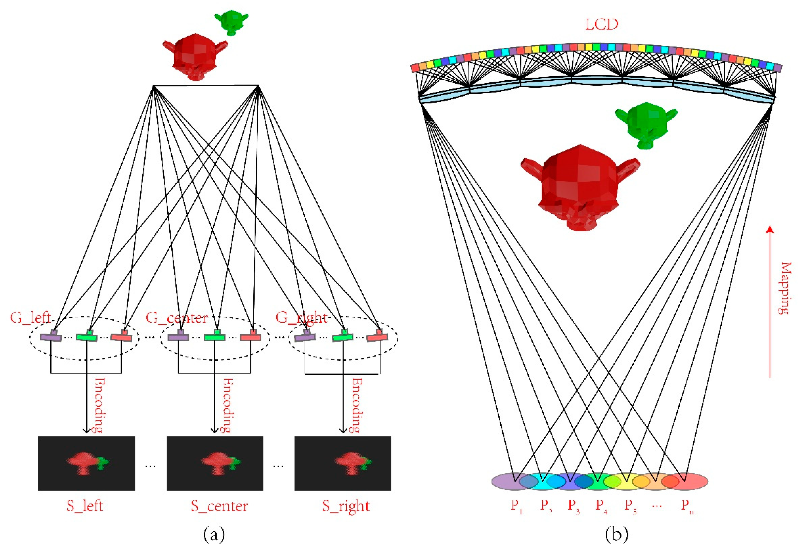
Figure 4a, the cameras are divided into six groups on the basis of different viewing zones to record parallax images, and the number of cameras in each group equals to the viewpoints number in the viewing zone. With this configuration, six groups parallax images which store the intensity and direction information of the light field are obtained.
The synthesized image of each viewing zone is obtained with the encoding algorithm which execute the process of pixels mapping. The mapping relationship is shown in
Figure 4b, with parallax images represented with different colors. Pixels of the parallax images are dispersed periodically and all parallax images in a group are synthesized to generate a single encoded image. Six group parallax images for different viewing zones are obtained with the virtual cameras array in a computer 3D modeling software. Each group contains seventeen parallax images.
3.2. Simulation
Simulations are carried out to verify the feasibility of the proposed light field display. A SMV light field model is built in the optical software to verify the viewpoints distribution. In the simulation model, an optical screen is placed at the OVD and the viewpoints are obtained by measuring the optical intensity distribution on the optical screen.
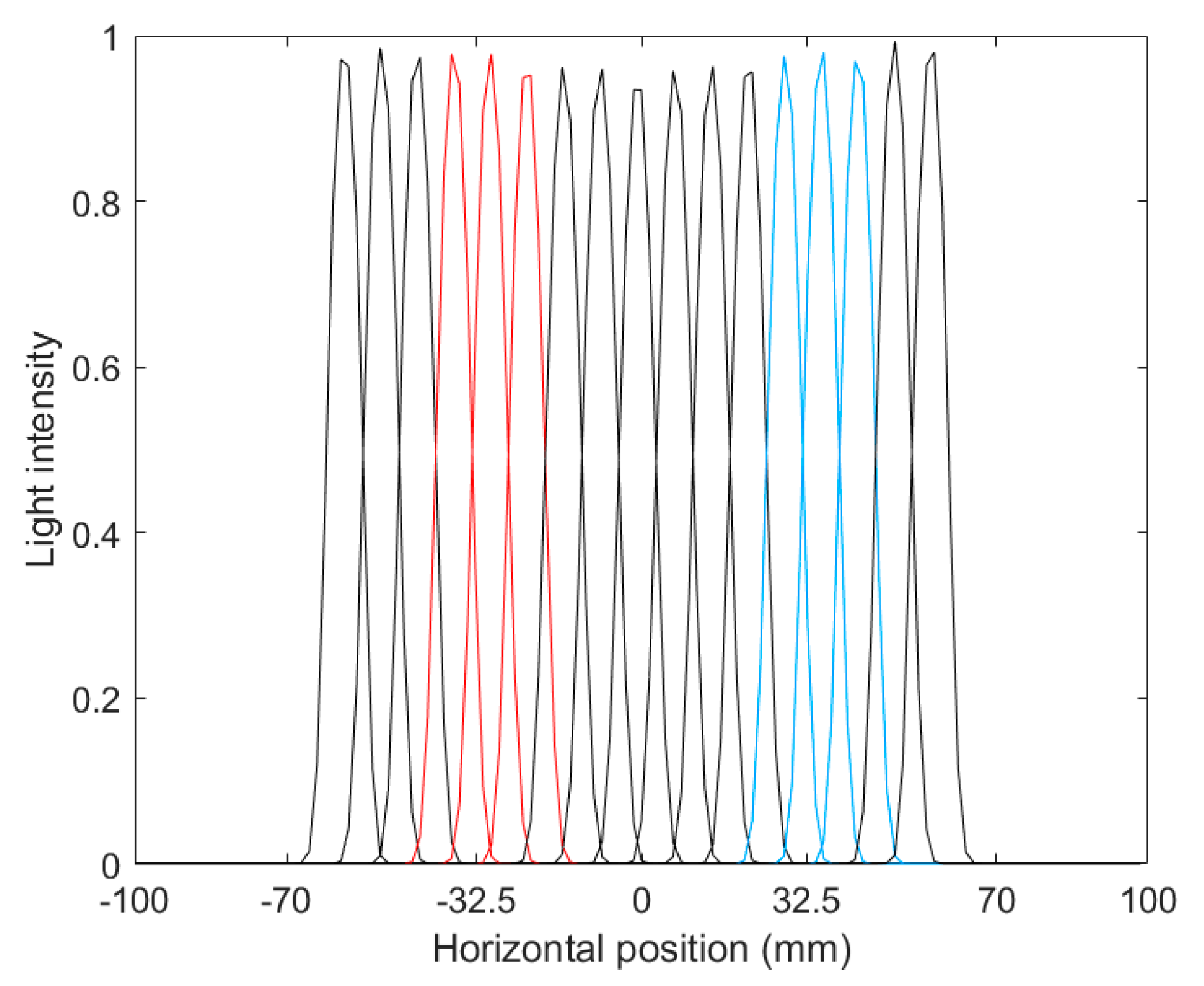
Figure 6 shows the measured viewpoints generated in a viewing zone.
As shown in
Figure 5, the measured viewpoints are uniformly distributed in a range of 130 mm. The distance between the center of the red lines and blue lines is about 63 mm, which equals to the average human binocular distance. The red lines illustrate the viewpoints for left eye, the blue lines illustrate that for right eye. The intersection part between the red and blue lines is extremely small, which means that the viewpoints perceived by left eye and right eye can be separated well and the crosstalk between left eye and right eye is imperceptible.
Figure 5.
The simulated viewpoints distribution.
Figure 5.
The simulated viewpoints distribution.
In addition, the intersection part between two adjacent viewpoints is remarkable, while the odd or even viewpoint can be separated well. With such a viewpoints arrangement, parallax between adjacent viewpoints can be smoothly shifted.
3.3. Experimental results
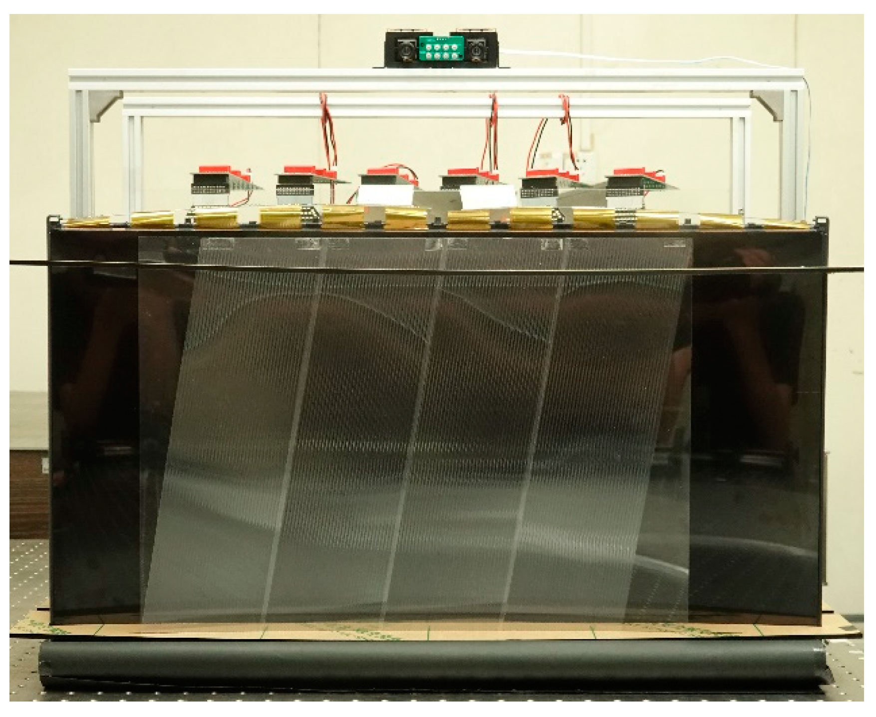
In order to verify the feasibility of the proposed light field display, a prototype was established and relevant experiments were conducted. The quasi-directional backlight module consists of 7 units arranged side by side to achieve uniform illumination, each unit contains a series of LEDs and LFL whose focal length is 123.4 mm. With the quasi-directional backlight,
15-degree illumination range can be achieved. A curved LCD whose radius curvature equals to 1451 mm was placed in front of the backlight module to load the encoded light field information. The LLA was tilted 9.46-degree (arctan1/6) and placed in front of the LCD to decode the light field information and generate viewpoints. Each lens of the LLA covers 17 pixels in horizontal direction. With such a system arrangement, the intervals of horizontal and vertical pixels in LCD panel for constructing the same viewpoints are 17 and 6 respectively. The horizontal resolution of 3D images can be calculated as 3840÷17=226 and the vertical resolution can be calculated as 2160÷6=360. Hence 3D images with the resolution of 226x360 can be perceived in each viewpoint. The detailed parameters of the prototype are listed in Table. 1.
Figure 6 shows the prototype of the proposed light field display system built in the experiment.
Figure 6.
The prototype of the proposed SMV light field display.
Figure 6.
The prototype of the proposed SMV light field display.
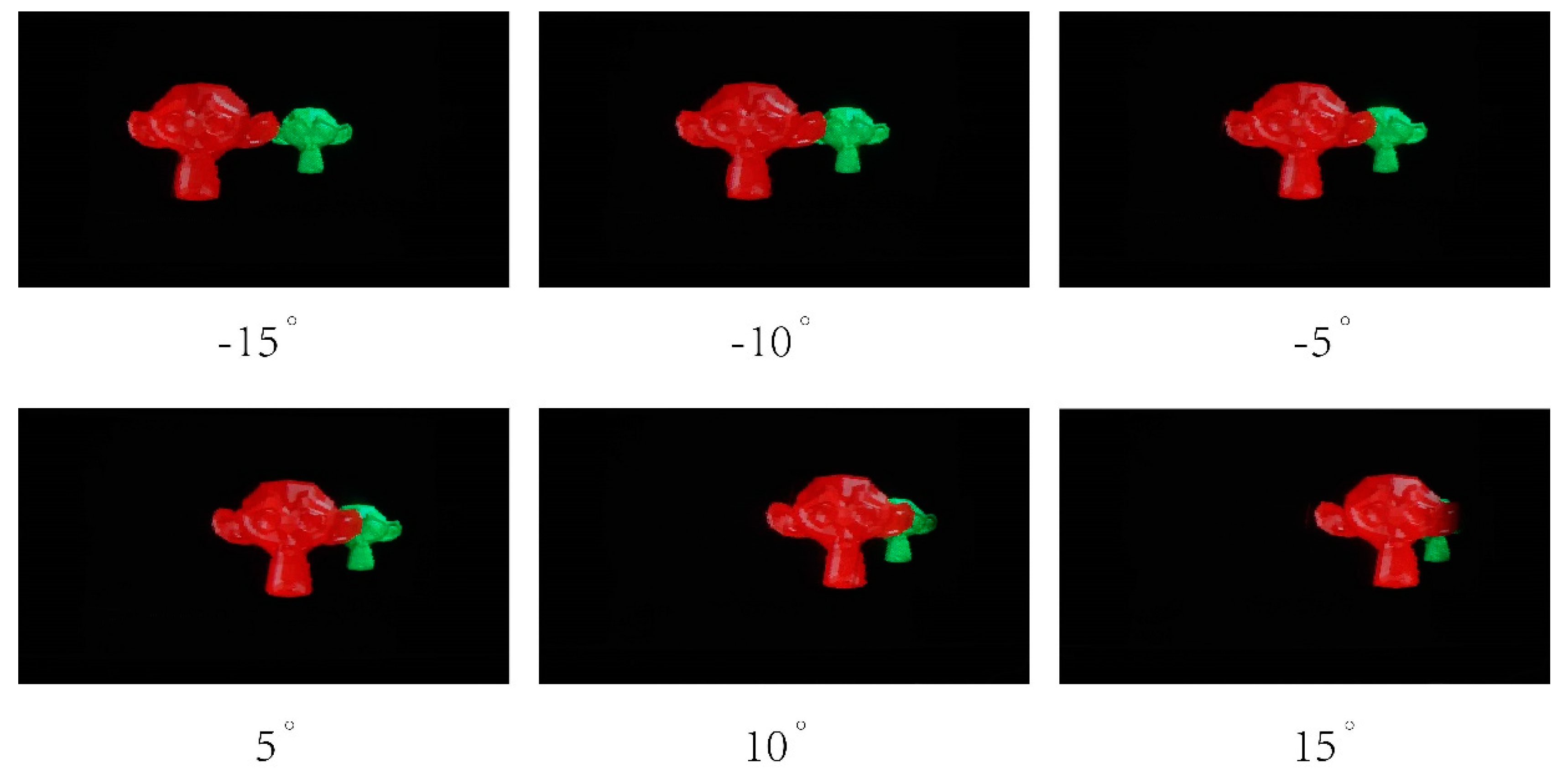
Figure 7 shows the 3D images reconstructed by the prototype, and the photographs were captured by a camera placed at the OVD (1451 mm in front of the prototype). Experiment results show that vivid 3D scene can be reconstructed with the proposed light field display.
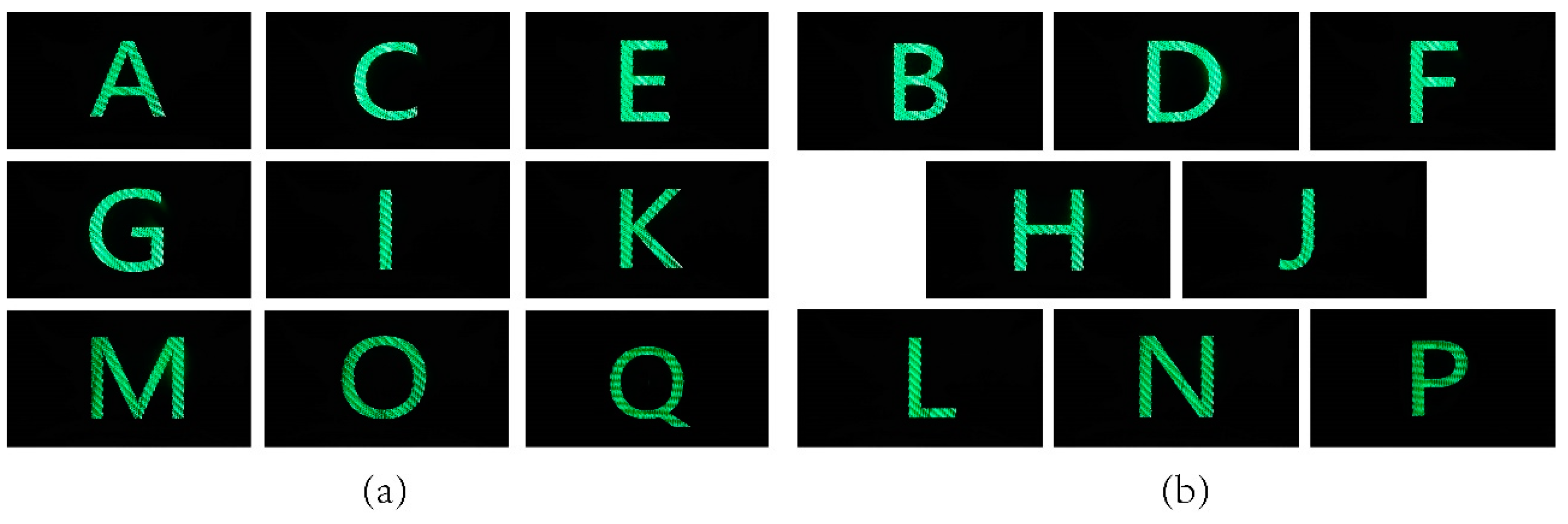
Viewpoints generated by the prototype were not measured directly, but images of different letters were encoded into a synthesized image that was then loaded on the prototype to evaluate the formation of viewpoints. 17 letters from A to Q were divided into two groups according to odd and even numbers, and each group was synthesized to generate a single image for test. In the synthesized process, letters were encoded at intervals of one viewpoint, and black images were encoded into the viewpoint between letters. A camera was placed at the OVD and moved a width of 130 mm to shoot the screen, the experiment results are shown in
Figure 8a,b.
Figure 8 shows that, when the letters were displayed at the intervals of one viewpoint, the odd or even viewpoint can be separated well and the crosstalk is imperceptible. The experiment results consistent well with the simulation results in
Figure 4. With such a viewpoints distribution, parallax between adjacent viewpoints can experience a smoothly transition. The proposed light field display can provide vivid 3D images with smooth motion parallax and low crosstalk.
4. Discussion
The proposed scheme reduces the redundant viewpoints and improves the information utilization rate by concentrating the information to a 5-degree range. 17 viewpoints are generated in the information transmission angle. Eye-tracking technique is further introduced to extend the total viewing range to 30-degree. With this configuration, dense up to 3.4 viewpoints per degree are achieved to ensure smooth motion parallax. 102 viewpoints are required for a conventional light field display with 30-degree viewing angle to achieve the same dense viewpoints, which means 102 parallax images with the resolution of 3840x2160 should be utilized to generate the encoded image.
With the same dense viewpoints, the pixels count applied to synthesize each frame image in the conventional light field display is 846x106 pixels, and approximately 20 billion (20.3x10⁹) pixels per second are required to process a video with 24 Hz frame rate. With the proposed scheme, the pixels count required for synthesizing each frame image decrease to 141x106 pixels, and a 24 Hz frame rate video can be provided by processing 3.4 billion (3.38x10⁹) pixels per second, the total data size decreases to 16.7% of conventional light field display, hence the scheme proposed in this work contributes to realizing a real-time render and display of light field information.
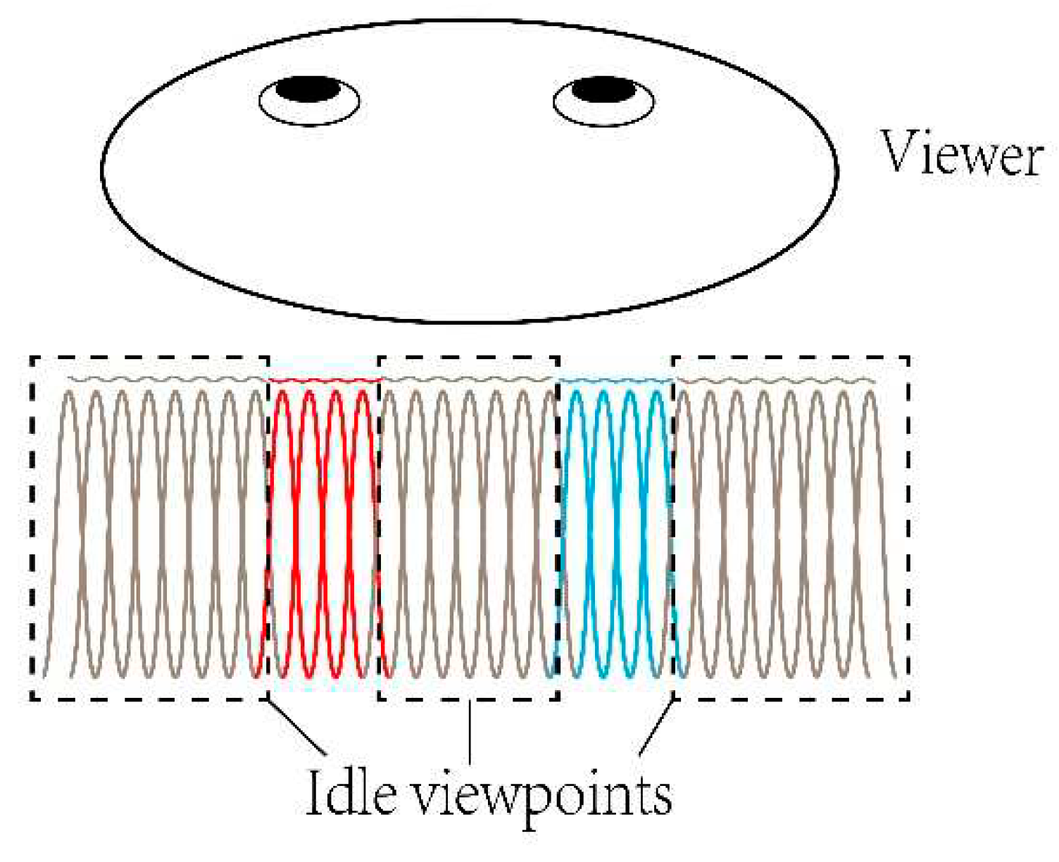
Besides, the viewpoints are uniformly distributed in the viewing zone whose width is set to the twice of the average human binocular distance in the proposed scheme. However, the effective viewpoints are the parts that situate in the periphery of pupils. As shown in
Figure 9, the red lines illustrate the viewpoints for left eye, the blue lines illustrate those for right eye, and the others are idle. Since the actually effective viewpoints are those around eye pupils, the quality of light field display can be further improved and the data size can be further reduced by reducing the idled viewpoints. It is possible to achieve the improved scheme by further concentrating the viewing area into human eye and combining with time-multiplexing technique to switch the information for left and right eye [
36].
The backlight module contains 7 units, the total number of columns is 68 in each of the 7 units, and each column consists of 21 LEDs. The directional autostereoscopic display system proposed in our previous work [
37] normally lightens 7 columns LEDs together in each unit to ensure the illumination width and provide homogeneous illumination over the entire screen for one eye. Since the illumination range are re-modulated by the LLA, each unit requires only 1 column LEDs (21x7=147 LEDs with a total power 3.6 W) with the same parameters for the proposed SMV light field display to provide the entire homogeneous illumination for a pair of eyes. Thus an illumination power of 3.6 watt is sufficient to lighten a 31.5-inch light field display,which takes up only 1.5% of the illumination power required for planar display of similar configuration.
A multi-user directional backlight autostereoscopic display was achieved in our previous work [
38]. In principle, the SMV light field display presented in this work can be easily improved into a multi-user one with the technique similar to the previous work. The backlight module in the SMV light field system can be controlled to generate multi illumination area. While the difference is that light field information varies with horizontal viewing position, LCD panel refreshing is required to update light field information for different viewing zone. Since the information transmission is always consistent with the illumination direction, multi-viewing zone can be achieved by synchronously adjusting the directional backlight to switch the illumination direction and refreshing LCD panel to update light field information. With this multi-user scheme, an LCD panel with 60 Hz refresh rate can achieve two 30 Hz viewing zone, the multi-viewing zone can be achieved at the cost of refreshing rate, hence an LCD panel with high refresh rate is required to improve the display effect.
5. Conclusions
In conclusion, a SMV light field display is proposed to concentrate the information in the viewing zone of a single user by reducing the redundant viewpoints. The quasi-directional backlight is proposed and an LLA with long focal length is applied to achieve the viewing zone, in which 3.4 viewpoints per degree are generated to ensure parallax saltation-free. The total horizontal observation area can be extended to 30-degree or above by further introducing eye-tracking technique. The prototype built in our experiment confirms that vivid 3D images with correct geometric occlusion and smooth motion parallax can be obtained.
With the system configuration, the illumination range is concentrated in the viewing zone of a single user and all pixels of the LCD panel are concentrated in the viewing zone to generate viewpoints, the information utilization rate and the energy efficiency are substantially improved. By reducing redundant viewpoints, total data size reduces to 16.7%, hence the requirements of information transmission bandwidth are reduced, which contributes to realizing a real-time render and display of light field information. This study further demonstrates that only a fraction of the illumination power of a planar display is required for directional light field display, making this display technology particularly attractive for general “green 3D display”.
Author Contributions
Conceptualization, G.Z. and Y.H.; methodology, G.Z., Y.H. and X.C.; software, G.Z.; validation, Y.H., H.L. and J.Z.; formal analysis, G.Z.; investigation, G.Z. and Y.H.; resources, J.Z., H.L. and D.D.; data curation, G.Z.; writing—original draft preparation, G.Z.; writing—review and editing, J.Z. and Y.H.; visualization, G.Z.; supervision, H.L. and J.Z.; project administration, J.Z.; funding acquisition, J.Z. and H.L. All authors have read and agreed to the published version of the manuscript.
Funding
This research was funded by National Key Research and Development Program of China, grant number 2021YFB2802200; and National Natural Science Foundation of China, grant number 12074444.
Data Availability Statement
Data is contained within the article.
Conflicts of Interest
The authors declare no conflict of interest. The funders had no role in the design of the study; in the collection, analyses, or interpretation of data; in the writing of the manuscript; or in the decision to publish the results.
References
- Liu, X.; Li, H. The Progress of Light-Field 3-D Displays. Information Display 2014, 30, 6–14. [Google Scholar] [CrossRef]
- Javidi, B.; Carnicer, A.; Arai, J.; Fujii, T.; Hua, H.; Liao, H.; Martinez-Corral, M.; Pla, F.; Stern, A.; Waller, L.; et al. Roadmap on 3D integral imaging: sensing, processing, and display. Optics express 2020, 28, 32266–32293. [Google Scholar] [CrossRef] [PubMed]
- Ma, Q.; Cao, L.; He, Z.; Zhang, S. Progress of three-dimensional light-field display [Invited]. Chinese Optics Letters 2019, 17, 111001. [Google Scholar] [CrossRef]
- Hoffman, D.M.; Girshick, A.R.; Akeley, K.; Banks, M.S. Vergence-accommodation conflicts hinder visual performance and cause visual fatigue. J Vis 2008, 8, 1–30. [Google Scholar] [CrossRef] [PubMed]
- J. P. Wann, S.R., and M. Mon-Williams. Natural problems for stereoscopic depth perception in virtual environments. Vision Research 1995, 35, 2731–2736. [CrossRef] [PubMed]
- Marc Levoy, P.H. Light Field Rendering. In Proceedings of the ACM SIGGRAPH; 1996; pp. 31–42. [Google Scholar]
- Lippmann, G. Épreuves réversibles donnant la sensation du relief. Journal de Physique Théorique et Appliquée 1908, 7, 821–825. [Google Scholar] [CrossRef]
- He, Y.; Chen, X.; Li, X.; Li, Z.; Fan, Y.; Ding, J.; Yan, Z.; Liang, H.; Zhou, J. Harnessing the plenoptic function for a directionally illuminated autostereoscopic display. Optics express 2022, 30, 45553–45568. [Google Scholar] [CrossRef]
- Chen, B.; Ruan, L.; Lam, M.L. Light field display with ellipsoidal mirror array and single projector. Optics express 2019, 27, 21999–22016. [Google Scholar] [CrossRef]
- Ma, S.; Lou, Y.; Hu, J.; Wu, F. Enhancing integral imaging performance using time-multiplexed convergent backlight. Appl Opt 2020, 59, 3165–3173. [Google Scholar] [CrossRef]
- Momonoi, Y.; Yamamoto, K.; Yokote, Y.; Sato, A.; Takaki, Y. Light field Mirage using multiple flat-panel light field displays. Optics express 2021, 29, 10406–10423. [Google Scholar] [CrossRef]
- Su, C.; Zhou, X.; Li, H.; Yang, Q.; Wang, Z.; Liu, X. 360 deg full-parallax light-field display using panoramic camera. Appl Opt 2016, 55, 4729–4735. [Google Scholar] [CrossRef] [PubMed]
- Yoshida, S. fVisiOn: 360-degree viewable glasses-free tabletop 3D display composed of conical screen and modular projector arrays. Optics express 2016, 24, 13194–13203. [Google Scholar] [CrossRef] [PubMed]
- Yasui, M.; Watanabe, Y.; Ishikawa, M. Wide viewing angle with a downsized system in projection-type integral photography by using curved mirrors. Optics express 2021, 29, 12066–12080. [Google Scholar] [CrossRef] [PubMed]
- Chen, G.; Ma, C.; Zhao, D.; Fan, Z.; Liao, H. 360 Degree Crosstalk-Free Viewable 3D Display Based on Multiplexed Light Field: Theory and Experiments. J. Disp. Technol. 2016, 12, 1309–1318. [Google Scholar] [CrossRef]
- Jae-Hyeung Park, J.K., Yunhee Kim and Byoungho Lee Resolution-enhanced three-dimension / two-dimension convertible display based on integral imaging. Optics express 2005, 13, 1875–1884. [CrossRef] [PubMed]
- Nago, Y.T.N. Multi-projection of lenticular displays to construct a 256-view super multi-view display. Optics express 2010, 18, 8824–8835. [Google Scholar]
- Qing Zhong, Q.Z.; Beishi Chen, B.C.; Haifeng Li, H.L.; Xu Liu, X.L.; Jun Xia, J.X.; Baoping Wang, B.W.; Haisong Xu, H.X. Multi-projector-type immersive light field display. Chinese Optics Letters 2014, 12, 060009–060013. [Google Scholar] [CrossRef]
- G. Wetzstein, D.L., M. Hirsch, W. Heidrich and R. Raskar. Compressive Light Field Displays. IEEE Computer Graphics and Applications 2012, 32, 6–11. [CrossRef]
- Chen, D.; Sang, X.; Yu, X.; Zeng, X.; Xie, S.; Guo, N. Performance improvement of compressive light field display with the viewing-position-dependent weight distribution. Optics express 2016, 24, 29781–29793. [Google Scholar] [CrossRef]
- Sang, X.; Gao, X.; Yu, X.; Xing, S.; Li, Y.; Wu, Y. Interactive floating full-parallax digital three-dimensional light-field display based on wavefront recomposing. Optics express 2018, 26, 8883–8889. [Google Scholar] [CrossRef]
- Wen, J.; Yan, X.; Jiang, X.; Yan, Z.; Fan, F.; Li, P.; Chen, Z.; Chen, S. Integral imaging based light field display with holographic diffusor: principles, potentials and restrictions. Optics express 2019, 27, 27441–27458. [Google Scholar] [CrossRef] [PubMed]
- Wen, J.; Jiang, X.; Yan, X.; Li, P. Dual-mode light field display with enhanced viewing range: From far distance viewable to near distance touchable. Optik 2022, 252, 168403. [Google Scholar] [CrossRef]
- Yu, X.; Sang, X.; Gao, X.; Chen, D.; Liu, B.; Liu, L.; Gao, C.; Wang, P. Dynamic three-dimensional light-field display with large viewing angle based on compound lenticular lens array and multi-projectors. Optics express 2019, 27, 16024–16031. [Google Scholar] [CrossRef] [PubMed]
- Liu, B.; Sang, X.; Yu, X.; Gao, X.; Liu, L.; Gao, C.; Wang, P.; Le, Y.; Du, J. Time-multiplexed light field display with 120-degree wide viewing angle. Optics express 2019, 27, 35728–35739. [Google Scholar] [CrossRef]
- Zhu, Y.; Sang, X.; Yu, X.; Wang, P.; Xing, S.; Chen, D.; Yan, B.; Wang, K.; Yu, C. Wide field of view tabletop light field display based on piece-wise tracking and off-axis pickup. Optics Communications 2017, 402, 41–46. [Google Scholar] [CrossRef]
- Naoto Okaichi, H.S., Masanori Kano, Jun Arai, Masahiro Kawakita, Takeshi Naemura. Integral three-dimensional display system with wide viewing zone and depth range using time-division display and eye-tracking technology. Optical Engineering 2022, 61, 013103.
- Okaichi, N.; Sasaki, H.; Kano, M.; Arai, J.; Kawakita, M.; Naemura, T. Design of optical viewing zone suitable for eye-tracking integral 3D display. OSA Continuum 2021, 4, 1415–1429. [Google Scholar] [CrossRef]
- Ueno, T.; Takaki, Y. Super multi-view near-eye display to solve vergence-accommodation conflict. Optics express 2018, 26, 30703–30715. [Google Scholar] [CrossRef]
- Yasuhiro Takaki, K.T., and Junya Nakamura. Super multi-view display with a lower resolution flat-panel display. Optics express 2011, 19, 4129–4139. [CrossRef]
- Yang, L.; Sang, X.; Yu, X.; Liu, B.; Yan, B.; Wang, K.; Yu, C. A crosstalk-suppressed dense multi-view light-field display based on real-time light-field pickup and reconstruction. Optics express 2018, 26, 34412–34427. [Google Scholar] [CrossRef]
- Wang, P.; Sang, X.; Yu, X.; Gao, X.; Yan, B.; Liu, B.; Liu, L.; Gao, C.; Le, Y.; Li, Y.; et al. Demonstration of a low-crosstalk super multi-view light field display with natural depth cues and smooth motion parallax. Optics express 2019, 27, 34442–34453. [Google Scholar] [CrossRef] [PubMed]
- Fan, H.; Zhou, Y.; Wang, J.; Liang, H.; Krebs, P.; Su, J.; Lin, D.; Li, K.; Zhou, J. Full Resolution, Low Crosstalk, and Wide Viewing Angle Auto-Stereoscopic Display With a Hybrid Spatial-Temporal Control Using Free-Form Surface Backlight Unit. J. Disp. Technol. 2015, 11, 620–624. [Google Scholar] [CrossRef]
- Cheung, G.; Velisavljevic, V.; Ortega, A. On dependent bit allocation for multiview image coding with depth-image-based rendering. IEEE Trans Image Process 2011, 20, 3179–3194. [Google Scholar] [CrossRef] [PubMed]
- Pang, B.; Sang, X.; Xing, S.; Yu, X.; Chen, D.; Yan, B.; Wang, K.; Yu, C.; Liu, B.; Cui, C.; et al. High-efficient rendering of the multi-view image for the three-dimensional display based on the backward ray-tracing technique. Optics Communications 2017, 405, 306–311. [Google Scholar] [CrossRef]
- Wang, J.; Liang, H.; Fan, H.; Zhou, Y.; Krebs, P.; Su, J.; Deng, Y.; Zhou, J. High-quality autostereoscopic display with spatial and sequential hybrid control. Appl Opt 2013, 52, 8549–8553. [Google Scholar] [CrossRef]
- Li, X.; Ding, J.; Zhang, H.; Chen, M.; Liang, W.; Wang, S.; Fan, H.; Li, K.; Zhou, J. Adaptive glasses-free 3D display with extended continuous viewing volume by dynamically configured directional backlight. OSA Continuum 2020, 3, 1555–1567. [Google Scholar] [CrossRef]
- Li, X.; Chen, X.; He, Y.; Li, Z.; Li, K.; Hu, J.; Liu, X.; Zhan, S.; Wang, S.; Deng, D.; et al. Multi-user, high-resolution, high-quality directional backlight autostereoscopic display. Optics Communications 2022, 520, 128456. [Google Scholar] [CrossRef]
|
Disclaimer/Publisher’s Note: The statements, opinions and data contained in all publications are solely those of the individual author(s) and contributor(s) and not of MDPI and/or the editor(s). MDPI and/or the editor(s) disclaim responsibility for any injury to people or property resulting from any ideas, methods, instructions or products referred to in the content. |
© 2023 by the authors. Licensee MDPI, Basel, Switzerland. This article is an open access article distributed under the terms and conditions of the Creative Commons Attribution (CC BY) license (http://creativecommons.org/licenses/by/4.0/).
