1. Introduction
Battery management system (BMS) plays a vital role in improving battery performance and optimizing vehicle operation in a safe and reliable manner because BMS is the connector between the battery and the vehicle. Consequently, considering the rapid growth of EV and HEV markets, there is an urgent need to develop a comprehensive and mature BMS. In this study, first we simulated the vehicle standard data in order to understand the AVL cruise then, similar vehicle is transformed into electric vehicle. Further analysis of developed model will be examined using AVL cruise and performance will be evaluated in real time environment. Further to optimise the battery performance, we are using different cell balancing techniques to increase the battery pack performance in MATLAB-SIMULINK. Today Rechargeable batteries are most widely used for many applications such as electrical appliances, smartphone, industry etc. They are considered as best option for electrical and hybrid vehicles due to their advantage of having High energy density, Low maintenance, more charge cycles, Low self-discharge rate. electric vehicle. Further analysis of developed model will be examined using AVL cruise and performance will be evaluated in real time environment. Further to optimise the battery performance, we are using different cell balancing techniques to increase the battery pack performance in MATLAB-SIMULINK. Today Rechargeable batteries are most widely used for many applications such as electrical appliances, smartphone, industry etc. They are considered as best option for electrical and hybrid vehicles due to their advantage of having High energy density, Low maintenance, more charge cycles, Low self-discharge rate compared to other batteries available in the market. But the due to low cell voltage of this cell we need high power battery pack to use them in case of electric vehicle. But considering the disadvantage of temperature rise in the cell we cannot use single battery cell in a bulk rather we have to use multiple cells connected in series to get higher output voltage as proven by Emadi et al.
Major factor that is affecting the uniformity of the cells is the non-uniform temperature distribution. Due to multiple charging and discharging cycles the net cell voltage will drift down and will cause decrease in the net capacity of the cell. For example, consider multiple cells connected in series, now cell with the higher internal impedance will show higher voltage than that of other cells connected in series. Till time other cells reach the maximum capacity first cell be overcharged and this will lead to increase in the temperature and the gaseous pressure within the cell causing its failure. Hence to increase the overall battery capacity and to avoid the battery failure battery management system has to be adopted. In this case we mainly focus on the cell balancing techniques to avoid overcharging of the cells for which we have two main methods: Passive and active balancing. The passive balancing technique uses shunt resistors to bypass the additional voltage in the form of heat during charging and discharging cycle (stuart et al and Zhang et al.). In case of active balancing charge from higher voltage cell is transferred to the lower voltage cell using active elements like capacitors and inductors and fly back DC-DC converters (Cao et al.,; Daowd et al., ; Kutkut et al., ; Moore et al.). Among various active balancing methods, capacitor cell balancing methods are widely used in various applications for their simplicity and scalability. There are several embodiments of capacitor cell balancing methods in the literature (West et al., ; Pascual et al., ; Baughman et al., ; Sang-hyun et al.).
Many researchers are using a computerized simulation with the help of AVL Cruise offers many advantages like reduced time and costs for vehicle development. It helps to refine the stage of the model at any step of the process. It also has various flexible options to interact with other simulation software like MATLAB-SIMULINK, etc. Cioroianu et at presented a model to be simulated in AVL Cruise in order to obtain data regarding vehicle performance, energy consumption and range on the new WLTC test cycle. The obtained results show a small range for vehicle. Hence, the proposed model was suitable for commuting or city driving. Obtained results also were helpful in future work in order to improve the range of vehicle by using higher capacity battery for simulation.
Li-qiang Jin et al have proposed a regenerative braking system for electric vehicle driven by in-wheel motors and a regeneration energy usage control strategy is set up. Then, a co-simulation test based on CRUISE and Simulink is conducted. The results of simulation show that the novel type of system can ensure the safety of battery pack and significantly improve the rate of energy regeneration. We can perform these tests on different driving cycle as per need. Ilimbatov et al. have obtained comparative results of the simulation of electric vehicle were plotted using Gazel test cycle. They compare the results from MATLAB Simulink with AVL Cruise. Similarly, IORGA Adrian et al. did a simulation on electric vehicle virtual model using NEDC cycle and simulation results were plotted using AVL cruise.
Yajuan Yang et al. proposed a paper, that aims at the parametric drive train design, modelling and performance simulation of a parallel diesel hybrid electric bus (PHEB). AVL/CRUISE and MATLAB/SIMULINK are used for modelling and simulation. The simulation tasks include fuel consumption calculation over the typical city bus drive cycle of China, maximum velocity calculation and acceleration time calculation. Iclodean C et al. proposed a novelty of scientific work is the implementation of four different types of batteries for Electric Vehicles on the same model to evaluate the vehicle's autonomy and the efficiency of these battery types on a driving cycle, in real time and digitized by computer simulation using AVL Cruise.
Many types of research have been carried out discussing techniques used for cell balancing and their causes and effects:
Zachary Bosire Omariba et. al. have presented a brief review explaining all the cell balancing techniques for optimizing battery performance under different temperature and mechanical vibration of battery. Despite of having many battery models. They considered Thevenin model circuit for analysis because of the consideration of temperature in study by capron et al.. They also discussed the balancing of cell at different modes like while cell charging, discharging and idle mode. Further, they discussed various active cell balancing and passive cell balancing methodologies . Along with-it various causes of battery imbalance and its effect on battery balancing are discussed. Therefore, battery balancing is critical due to the variation in parameters of battery.
Yuanmao Ye et. al developed a novel voltage equalizer for multi series battery strings based on the two-phase switched capacitor technique. This is derived according to Kirchhoff’s voltage and Kirchhoff’s current law. Further, they analysed the different circuit configuration and operational principle. This proposed two phased switched capacitor equalizer overcomes the drawback of conventional switching circuit, to transfer the charge from higher voltage cell to low voltage cell directly. This also reduces the balancing time significantly.
Moon Young Kim et. al. have developed a switched capacitor circuit in order to increase the balancing speed between the two cells which are away from each other. They proposed two switching chain structure one with additional switches and another with extra capacitor. So that the uppermost cell can made adjacent to the under most cell with help of additional switches and capacitor. In performance comparison, it is found that the balancing speed is much faster than the conventional one.
Yandong Wang et. al. has proposed a new strategy to increase the speed of switched-capacitor balancing. The system is based on two-phase switched capacitor technique. The proposed system is compact as compared to its conventional counterparts. The system under consideration is controlled by pair of complementary pulse signals with fixed switching frequency. The proposed system is superior for multi cell operation in Li ion battery packs. The downside of using such system is that it uses large number of switches.
Antonio Manenti et.al Has proposed a BMS model using a new cell balancing architecture based on cell redundancy, which is results of cells being connected in series to get high voltage systems. The proposed system is aimed at reducing the cost and space requirements of a battery management system. The control algorithm is developed by keeping in mind the aims mentioned above. The developed algorithm is tested and validated using prototype circuit development and implementation on 4 cell battery pack. The offered advantage is optimal balancing and reliability while operation while reducing cost and complexity. But the downside is that system can be used only up to 500W power application i.e. electric scooters and bikes.
Mohamed Daowd et. al. has proposed a battery management system (BMS) dependent on battery pack modularization architecture. The proposed system has management systems on various systems levels of a battery pack. The more efficient single switched capacitor (SSC) control strategy is advised to be used to balance the battery cells in the module (inside module balancing, IMB).
The Battery management system also includes the thermal management of cells along with the Charging and discharging control using a Bidirectional DC/DC Power Converter. The whole system was simulated on MATLAB using a 12-cell battery pack and a prototype controller is also designed and tested for system validation on 4cell Li-Ion battery pack.
The prime objective of this investigation is using MATLAB-SIMULINK software develope a control technique for cell balancing to reduce the balancing time for each cell in the battery pack to attain the optimum responses (charge-discharge, variation of SOC of each cell, etc). Further, it was also intended to implement or do a co-simulation of proposed technique in Simulink with the vehicle model in AVL Cruise.
2. Electric Vehicle Modelling
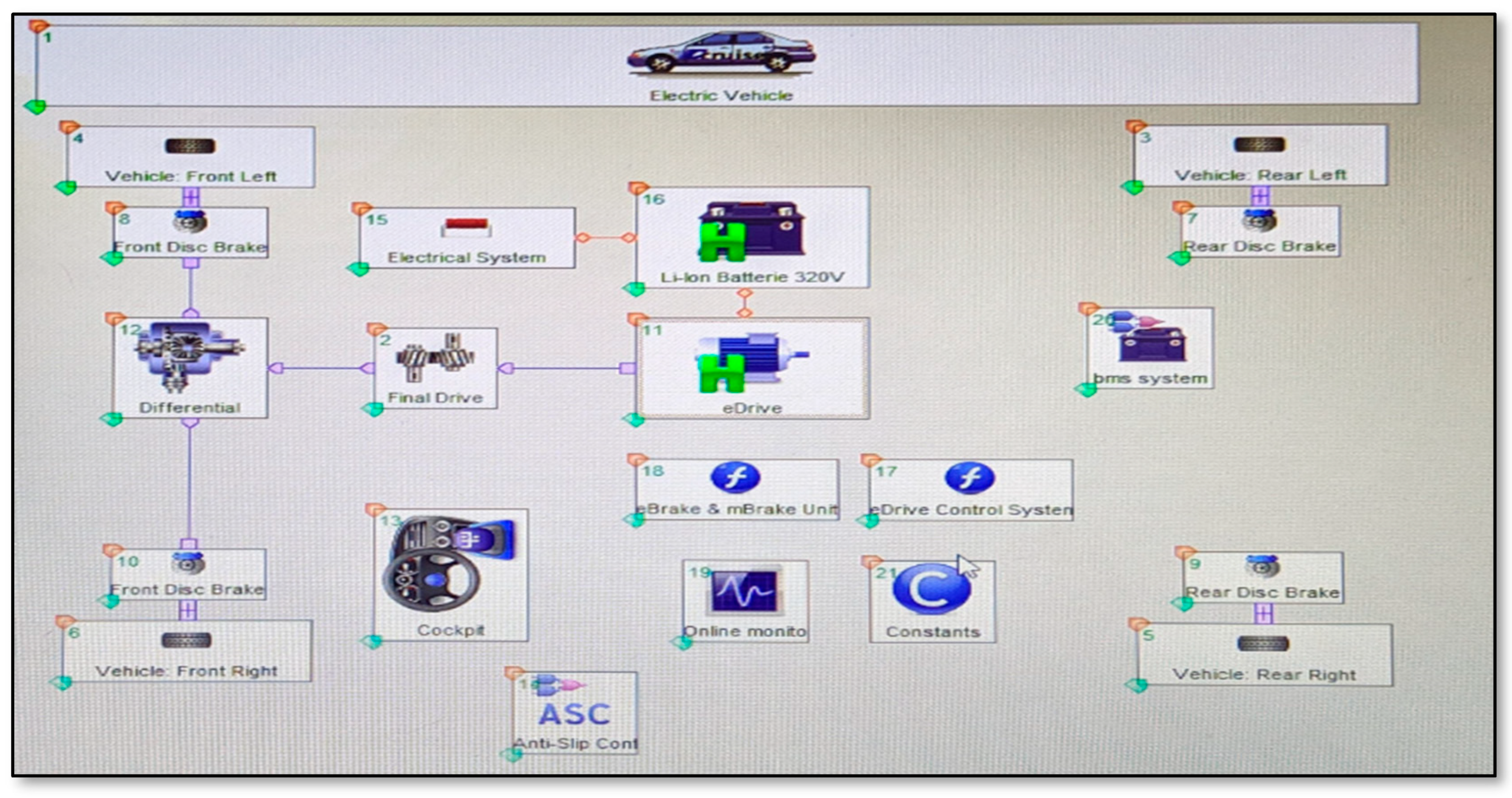
To determine the energy consumption of light weight electric vehicle generally Worldwide harmonized Light vehicles Test Procedures (WLTC) cycle is widely used.
Figure 1.
Battery-Electric vehicle model in AVL cruise.
Figure 1.
Battery-Electric vehicle model in AVL cruise.
The main characteristics of the WLTC test procedure are (data used from [27] for validation):
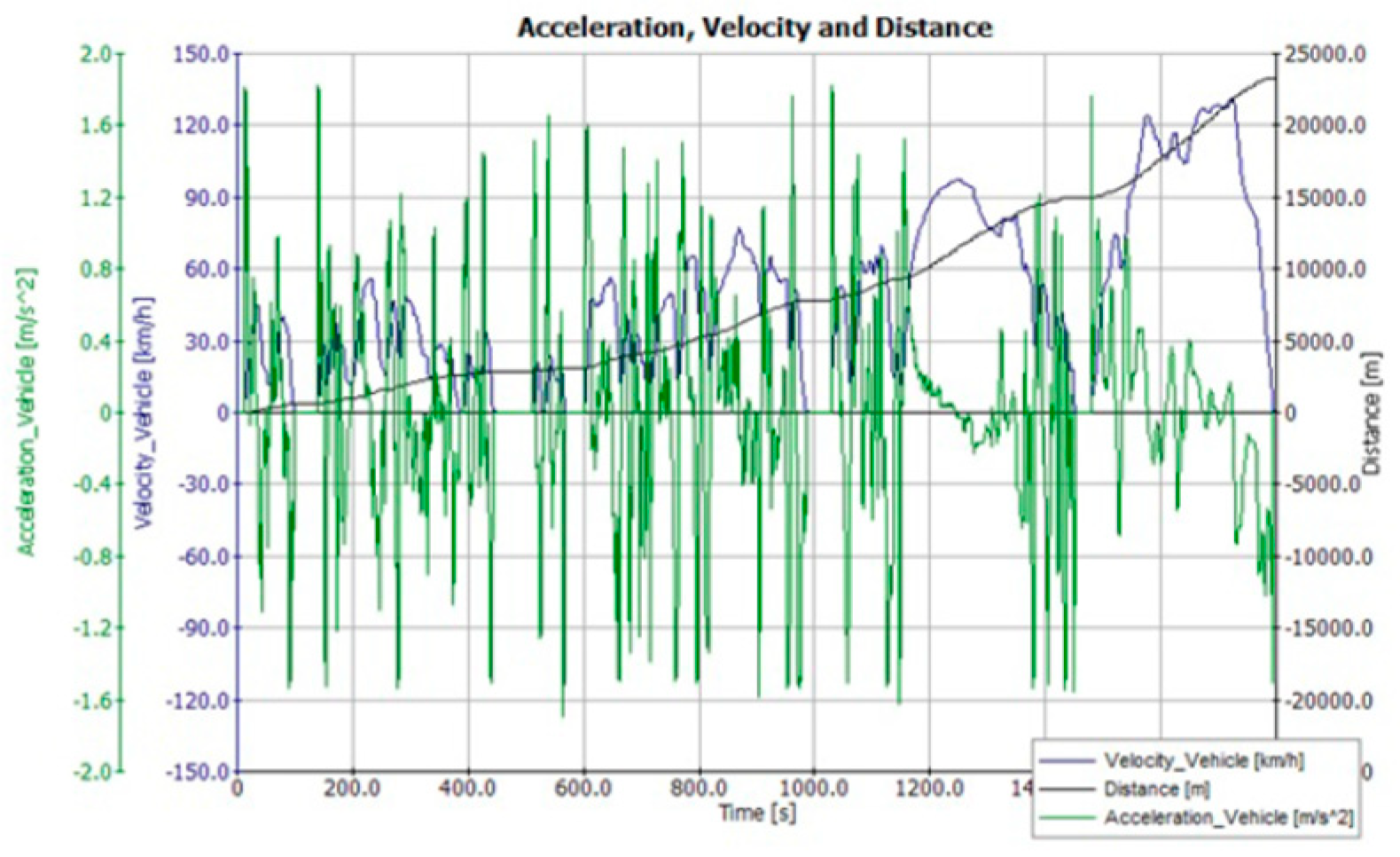
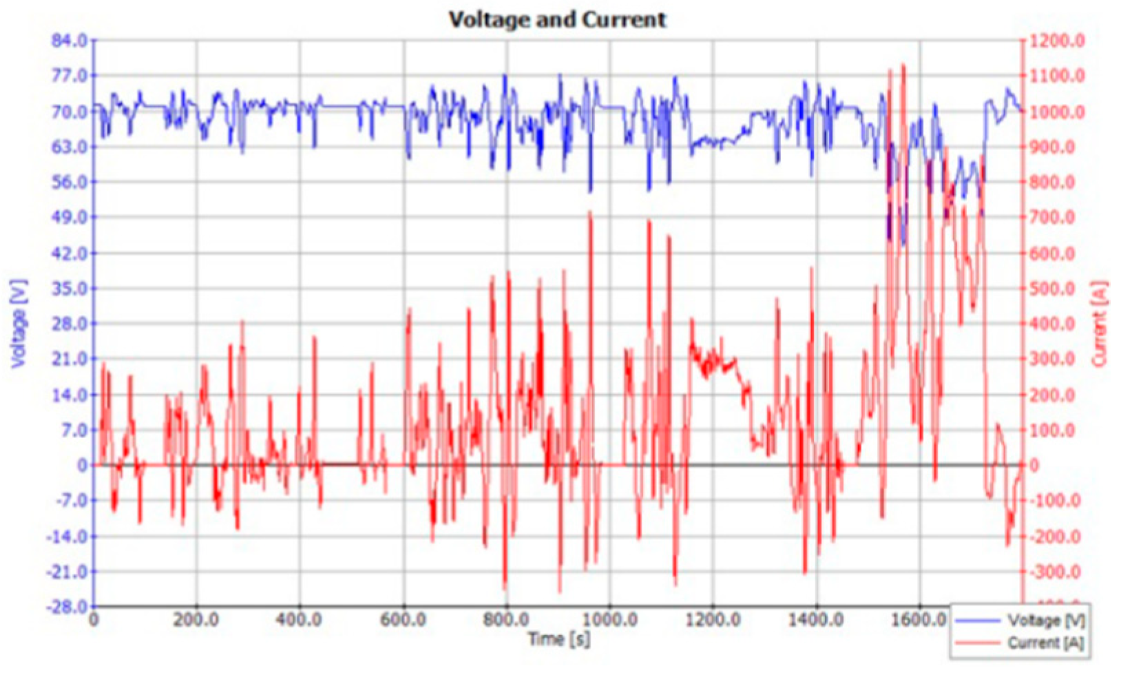
Based on the WLTC simulation carried out in AVL cruise graphs for total current and voltage required for the complete cycle can be obtained. It is also possible to determine the error in the velocity of the vehicle and the driving cycle. Based on the data obtained the total energy consumption is obtained which helps to determine the battery power capacity required. This also helps us to determine the range of the vehicle.
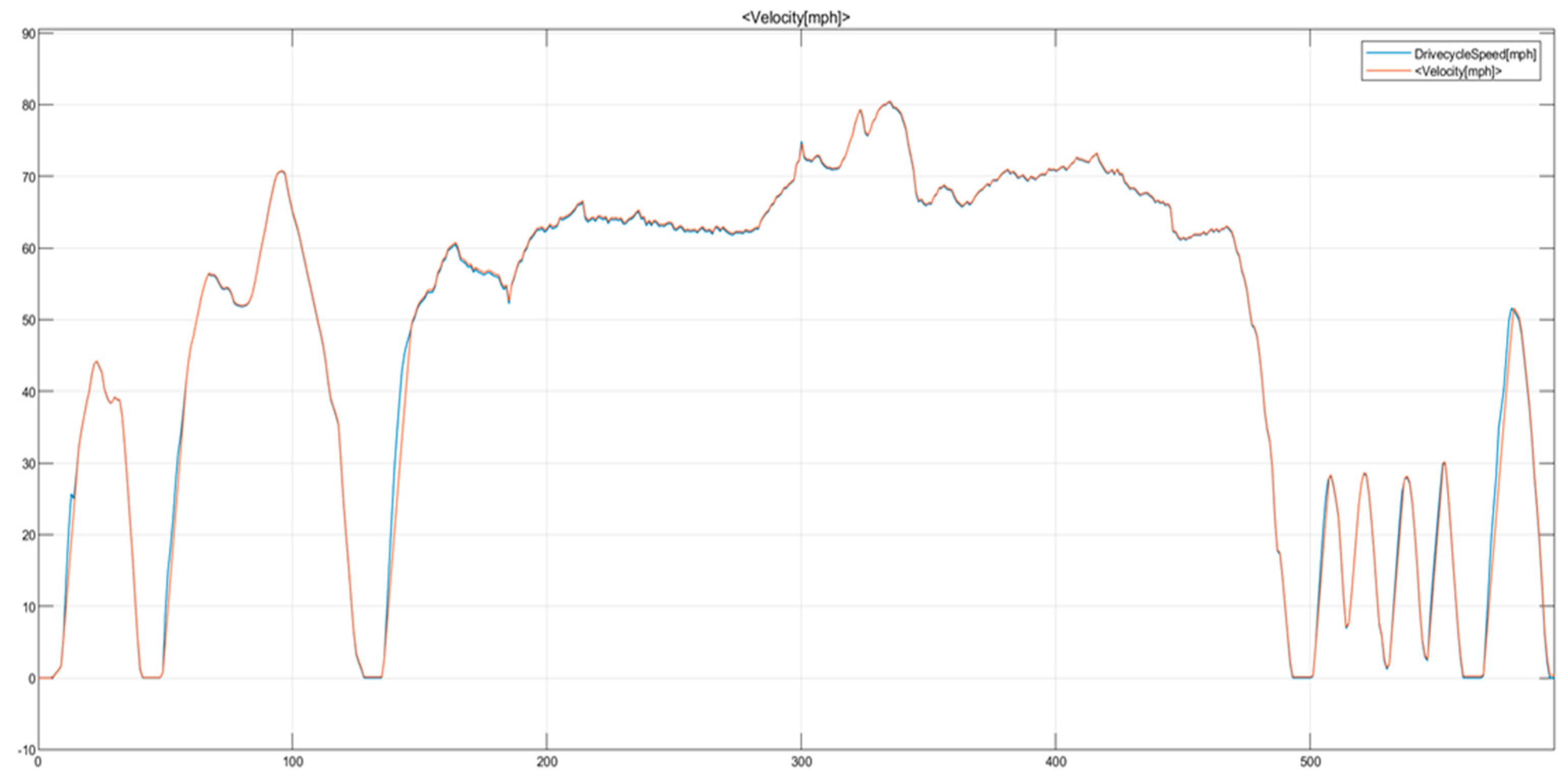
Figure 2 shows the characteristics of the WLTC cycle used in the investigation.
Figure 3 shows the variations of voltage and current during the WLTC cycle operation. It is observed from the above figure that during acceleration phases, battery voltage drops because it is under load. During decelerating phases, the current has negative values. This happens because the vehicle has regenerative braking, and the battery is being charged during these phases.
Battery pack Design
There are many battery cells available but considering the specific energy of lithium ion battery most of the automobile use lithium ion cells to develop a battery pack. Based on the required output capacity we can design the battery pack. For an electric vehicle very high voltage rating is required and battery pack required is thereby of higher capacity. This high-power output can be obtained by connecting cells in series and parallel.
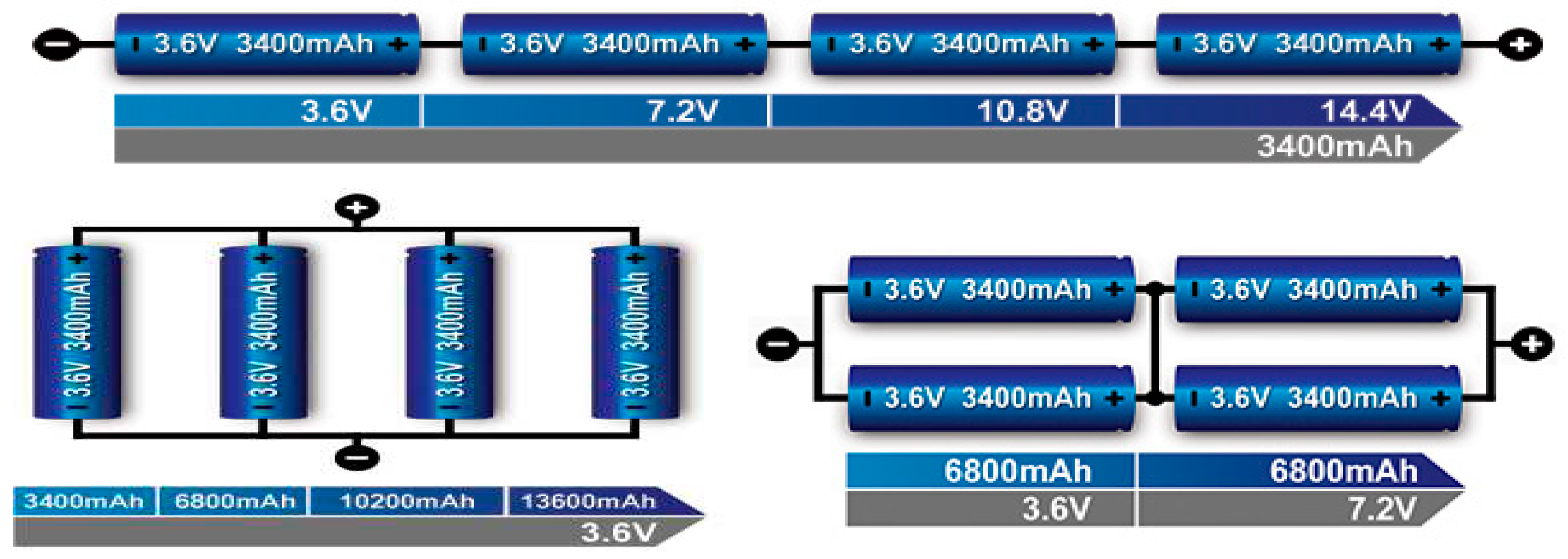
Figure 4. explain the battery architecture.
From
Figure 4, we can see that when batteries are connected in series net voltage across the circuit is increased whereas when connected in parallel the Amp-hours (Ah) capacity of the battery is increased (i.e. the amount of current that will flow across the circuit to run the motor).
e.g. cells with 6.5Ah ratting and we three parallel stack then total ratting would be 3*6.5=19.5Ah. Power rating of the battery depends on the total terminal voltage of the battery. Which is given by the below relation:
Where U = Voltage and I = Current.
Higher current across the circuit generates higher thermal heat so one has to consider optimum value for voltage as well for the current ratting. Also, appropriate cooling system has to be considered for heat dissipation across the battery pack.
Xianzhi Gong et.al. in his paper have mentioned the design consideration and the effect of cell unbalance on the battery pack. He has also descried the effect considering two cells and simulated in results in MATLAB Simulink. Omariba et. al. has given mathematical model and relations to develop a battery pack.
Designing of Motor and Battery
The propulsion unit of the vehicle delivers the force necessary to move the vehicle forward this force of the propulsion unit helps the vehicle to overcome the resisting forces like gravity, air and tire resistance.
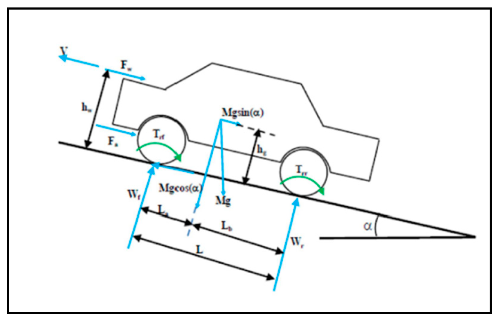
To find the longitudinal performance characteristics of a car we need to consider first the forces acting on it while travelling in a straight line. The major external forces acting on a two-axle vehicle are:
Aerodynamic resistance Ra
Rolling resistance Rr of the front and rear tires Rrf and Rrr
Drawbar load RD
Grade resistance RG, (W sin θ)
Tractive effort of the front and rear tires Ff and Fr (For a rear-wheel-drive vehicle, Ff = 0, whereas for a front-wheel vehicle, Fr = 0)
Figure 5.
Free body diagram of vehicle.
Figure 5.
Free body diagram of vehicle.
Total aerodynamic drag acting on the vehicle is given by:
Where:
V = Vehicle Velocity
= Air Density
Cd = Drag Coefficient
Af = Frontal Area
Rolling Resistance acting on vehicle due to tyre is composed primarily of
1. Resistance from tire deformation
2. Tire penetration and surface compression
3. Tire slippage & air circulation around wheel
4. Range of factors affect total rolling resistance
Total rolling resistance acting on the vehicle due to tyre is:
Total gradient resistance acting while climbing the slope is
Combination of all above forces will give us the total force acting on the vehicle at that constant speed.
Total Vehicular Resistance at Constant Velocity:
Power rating required by the motor can be given as:
Where V is Vehicle speed in m/s.
Design of Motor
Motor has to develop a torque that is required by the vehicle based on the resistive forces acting on it. Power output of the motor will be determined by considering the losses. Below is the total power developed by the motor.
Net power input provided by the motor is given by below relation which will account for the losses. This power will be further transferred to the drivetrain.
Total energy required by the motor can be determined by integrating the power that motor has developed. Based on the above calculation.
T = 27.35 Nm at 393.206 RPM
Using motor catalogue motor selected is PM BLDC 2000W,48V,4200RPM.
Battery Rating
Design of battery capacity is based on the power requirement of the motor. Total power input to the motor is equal to the total power output from the battery. Considering that below relation will help to get the total power required by the vehicle. Ideal power is to total power of the battery pack which will depend on the voltage and current capacity of the pack.
But to internal resistance of battery there will be losses in power output this loss is given by the relation:
Therefore, actual power required by the motor will be given by,
Therefore, net output power available at battery will be:
Battery Capacity
Range of electric vehicle based on the battery capacity is given by the relation:
Table 1.
Vehicle Parameters.
Table 1.
Vehicle Parameters.
| VEHICLE PARAMETERS |
|---|
| Aerodynamic Drag Coefficient |
0.38 |
| Air Density |
1.23 |
| Front Area |
2.1 |
| Mass of Vehicle |
2300 |
| Rolling Resistance Coefficient |
0.01 |
| Wheel Radius |
0.34 |
| Accessory Load |
600 |
| Vehicle Speed |
50kmph |
| Gear reduction Ratio |
3.55 |
Table 2.
Tractive force required to move vehicle.
Table 2.
Tractive force required to move vehicle.
| Gradient |
Radian |
Gradient Resistance(N) |
Aerodynamic Drag(N) |
Rolling Resistance(N) |
Tractive Force (N) |
| 0 |
0 |
0 |
96.19092 |
225.63 |
321.82092 |
| 1 |
0.0174444 |
393.5790377 |
96.19092 |
225.63 |
715.3999577 |
| 2 |
0.0348888 |
787.0383089 |
96.19092 |
225.63 |
1108.859229 |
| 3 |
0.0523333 |
1180.258084 |
96.19092 |
225.63 |
1502.079004 |
| 4 |
0.0697777 |
1573.118705 |
96.19092 |
225.63 |
1894.939625 |
| 5 |
0.0872222 |
1965.500624 |
96.19092 |
225.63 |
2287.321544 |
| 6 |
0.1046666 |
2357.28444 |
96.19092 |
225.63 |
2679.10536 |
| 7 |
0.1221111 |
2748.350933 |
96.19092 |
225.63 |
3070.171853 |
| 8 |
0.1395555 |
3138.581099 |
96.19092 |
225.63 |
3460.402019 |
| 9 |
0.157 |
3527.856192 |
96.19092 |
225.63 |
3849.677112 |
| 10 |
0.1744444 |
3916.057756 |
96.19092 |
225.63 |
4237.878676 |
| 11 |
0.1918888 |
4303.067659 |
96.19092 |
225.63 |
4624.888579 |
| 12 |
0.2093333 |
4688.768135 |
96.19092 |
225.63 |
5010.589055 |
Table 3.
Battery Capacity required to propel the vehicle.
Table 3.
Battery Capacity required to propel the vehicle.
| Power(W) |
Torque at Wheel (Nm) |
Motor RPM Required |
Motor Torque (Nm) |
Accessory Load(W) |
Battery Capacity (kWh) |
| 4505.49288 |
17.23523379 |
686.4820798 |
4.854995434 |
600 |
7.65823932 |
| 10015.59941 |
38.31349909 |
686.4820798 |
10.79253495 |
600 |
15.92339911 |
| 15524.02921 |
59.38535025 |
686.4820798 |
16.72826768 |
600 |
24.18604381 |
| 21029.10605 |
80.44437509 |
686.4820798 |
22.66038735 |
600 |
32.44365908 |
| 26529.15475 |
101.4841653 |
686.4820798 |
28.58708883 |
600 |
40.69373212 |
| 32022.50162 |
122.4983185 |
686.4820798 |
34.5065686 |
600 |
48.93375243 |
| 37507.47505 |
143.4804401 |
686.4820798 |
40.41702538 |
600 |
57.16121257 |
| 42982.40594 |
164.4241451 |
686.4820798 |
46.3166606 |
600 |
65.37360891 |
| 48445.62827 |
185.3230604 |
686.4820798 |
52.203679 |
600 |
73.5684424 |
| 53895.47957 |
206.1708265 |
686.4820798 |
58.07628914 |
600 |
81.74321936 |
| 59330.30146 |
226.9610992 |
686.4820798 |
63.932704 |
600 |
89.89545219 |
| 64748.44011 |
247.6875522 |
686.4820798 |
69.77114146 |
600 |
98.02266016 |
| 70148.24677 |
268.3438783 |
686.4820798 |
75.58982487 |
600 |
106.1223702 |
Based on Table II and Table III calculation it is found that the capacity of battery re-quired is around 8 kWh on plain road when vehicle is running at a speed on 50 kmph. And that on the road with 12-degree gradient battery capacity required is equivalent to 100 kWh. But in actual road driving scenario we don’t drive at constant speed rather it depends on the driving condition due to which the theoretically calculated capacity is to high. Hence to determine the actual performance we simulate the vehicle model in AVL Cruise software or in MATLAB. We can consider the mean velocity of the driving cycle and calculate the power and capacity required using above calculations.
Motor selected is BLDC 2kW, 48V, 4200 RPM, 60Amps;
So, battery pack required would be 48V, 60Amps;
Cells in series = 48/3.7 = 13;
Cells in parallel = 60/2.5 = 24;
Total number of cells required = 37.
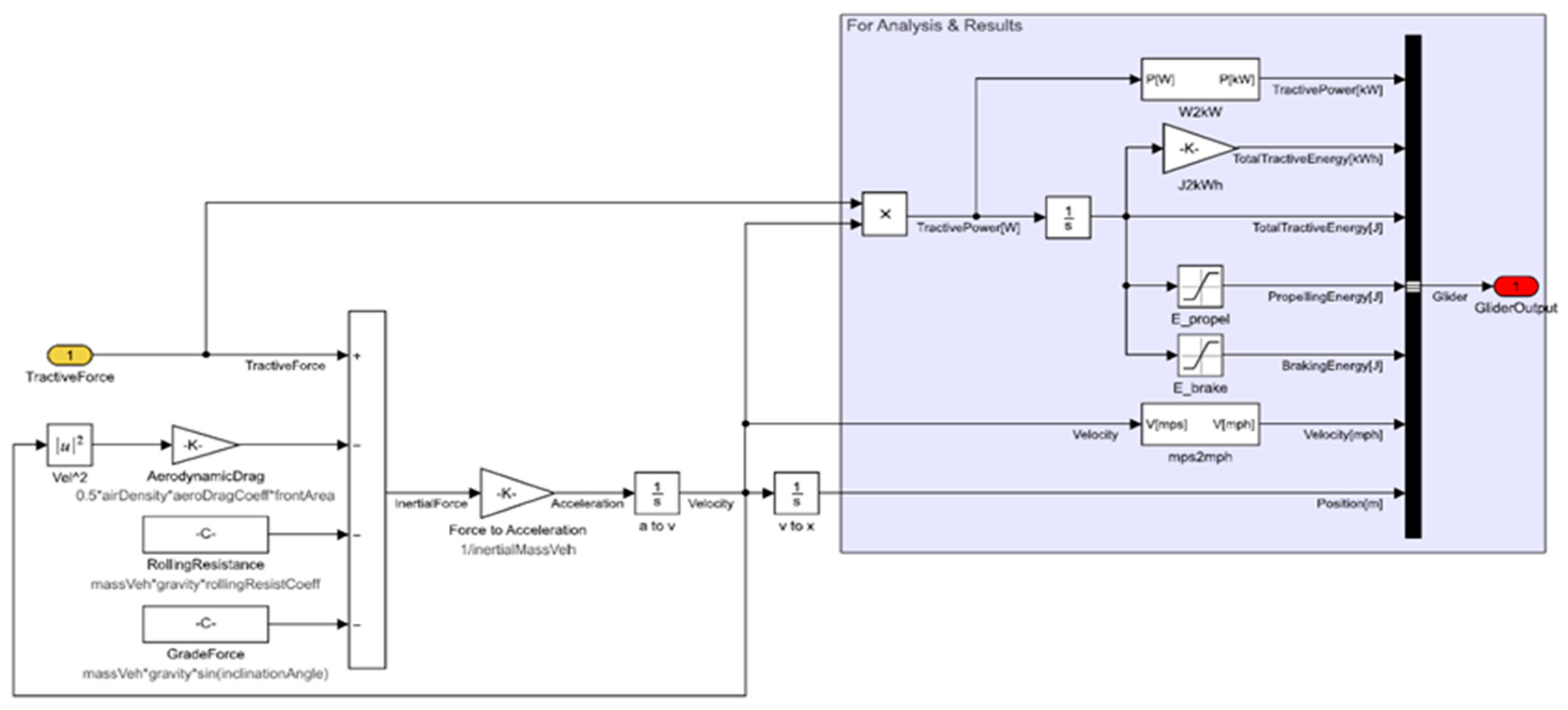
A Matlab model of a vehcle was developed to investigate the design and it is shown in
Figure 6.
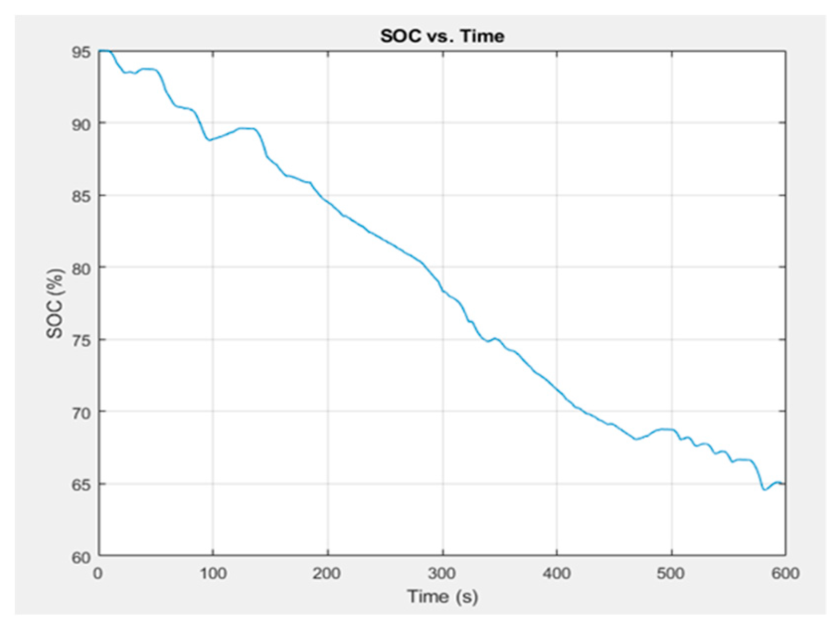
Figure 7 shows the state of charge as the time progresses. It also implies that the battery capacity available reduces as the time elapses.
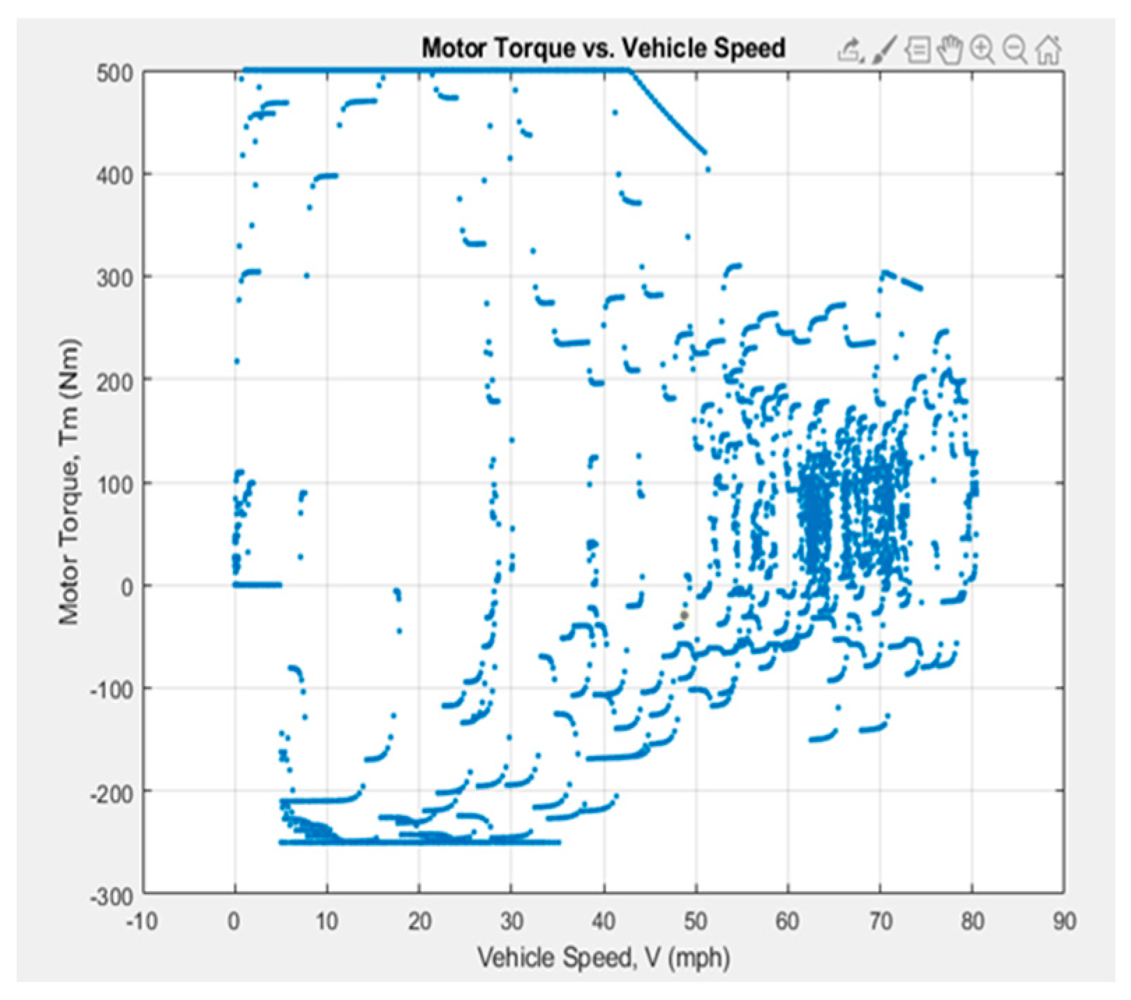
Figure 8 Shows at all the points at which my motor is operating at. From
Figure 8. we can understand that at a speed of 25-35 mph motor is operating a lot. Graph also helps to decide the size of the motor based on the working point distribution. If points are running out from the Torque line means we need to have larger motor for that particular drive cycle.
From the
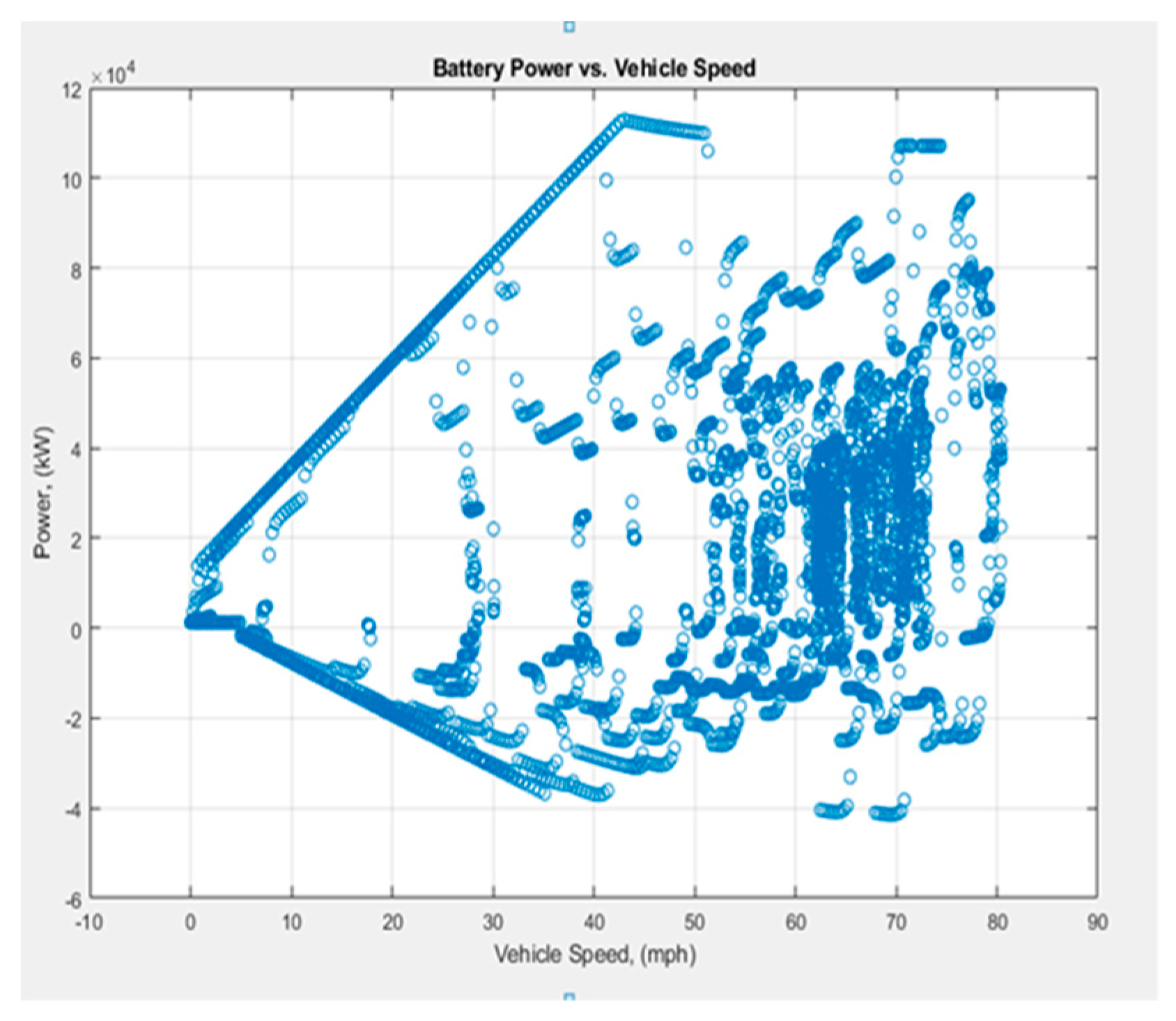
Figure 9 we can observe that the large quantity of battery power will be utilized at 50 to 80 kmph.
Worldwide harmonized Light vehicles Test Procedures used in the investigation is shown in
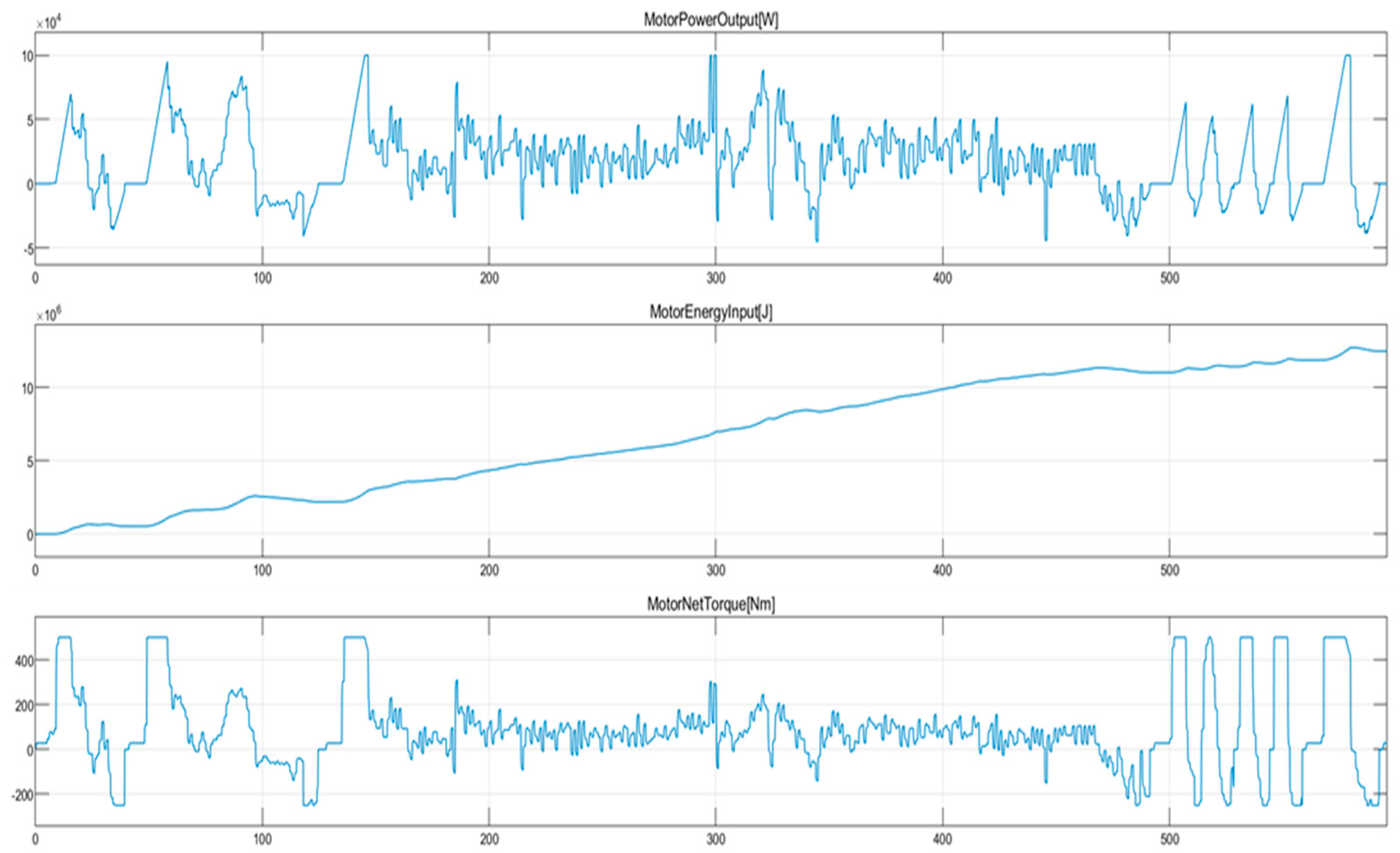
Figure 11. It is the ideal cycle to determine the energy consumed by the vehicle. The power output, energy consumed and net torque developed by the vehicle under the WLTC cycle is shown in
Figure 10. It shows the energy consumption data which is utilized to develope a battey management system.
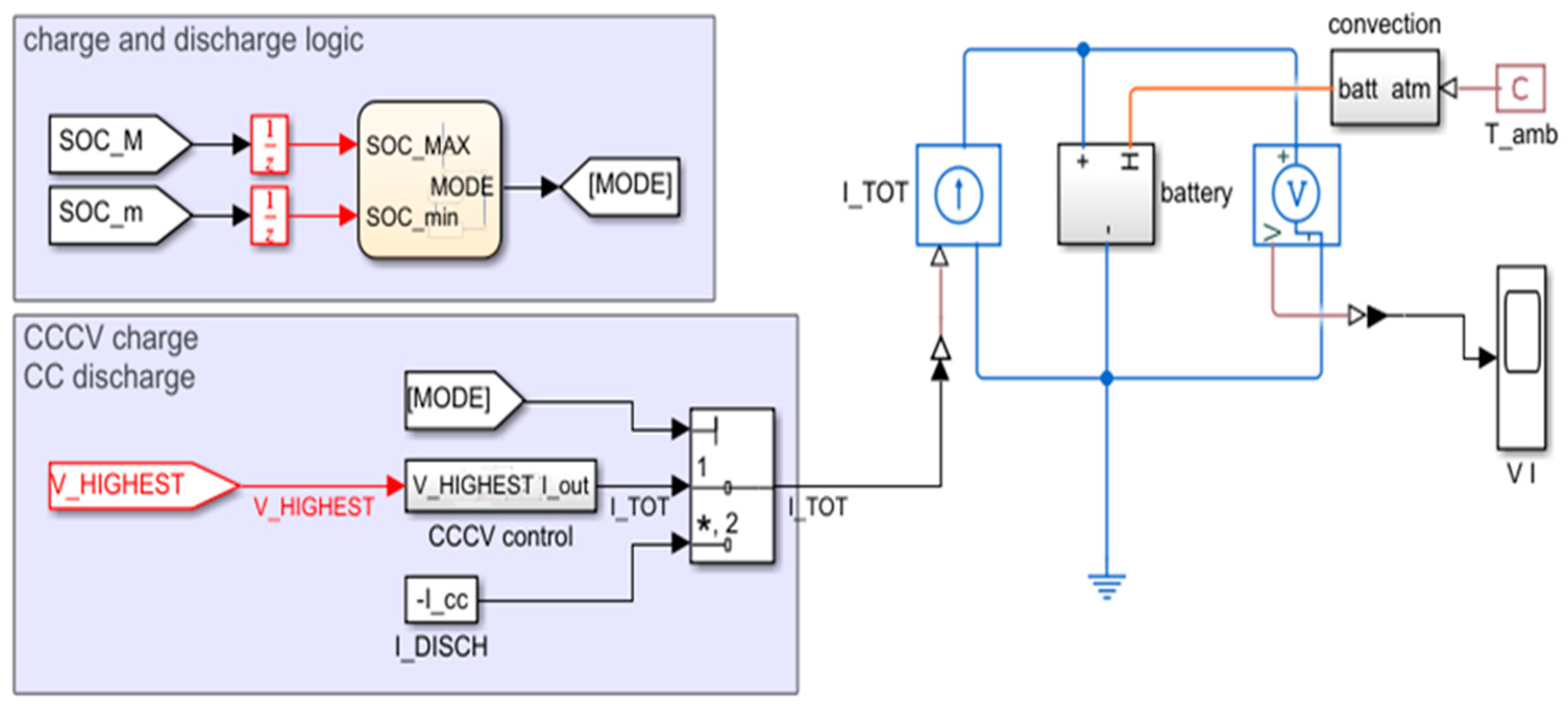
Battey Management system using Matlab-Simulink: Battery performance is mainly dependent on the BMS. Battery management system (BMS) mainly helps to identify the state of charge, state of health and cell balancing during charging and discharging of the battery. In this model we have trying to adopt for different cell balancing that can be used in the BMS to increase the battery performance and life. Proper cell balancing helps to reduce cell degradation and hence increases the battery life. We have defined two techniques to check the performance of the battery pack. Optimization of balancing time is expected from these cell balancing techniques.
Passive Cell Balancing Technique
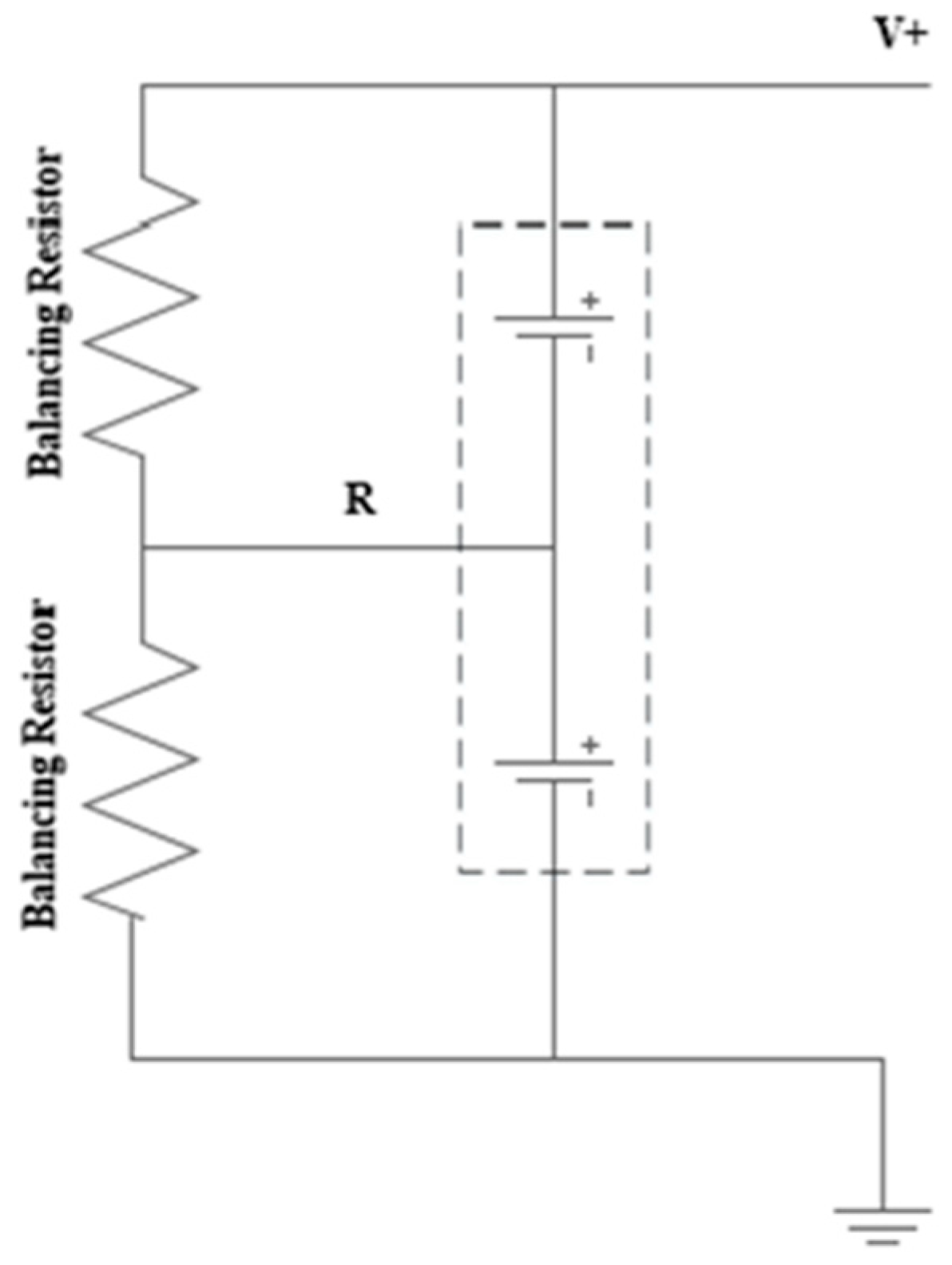
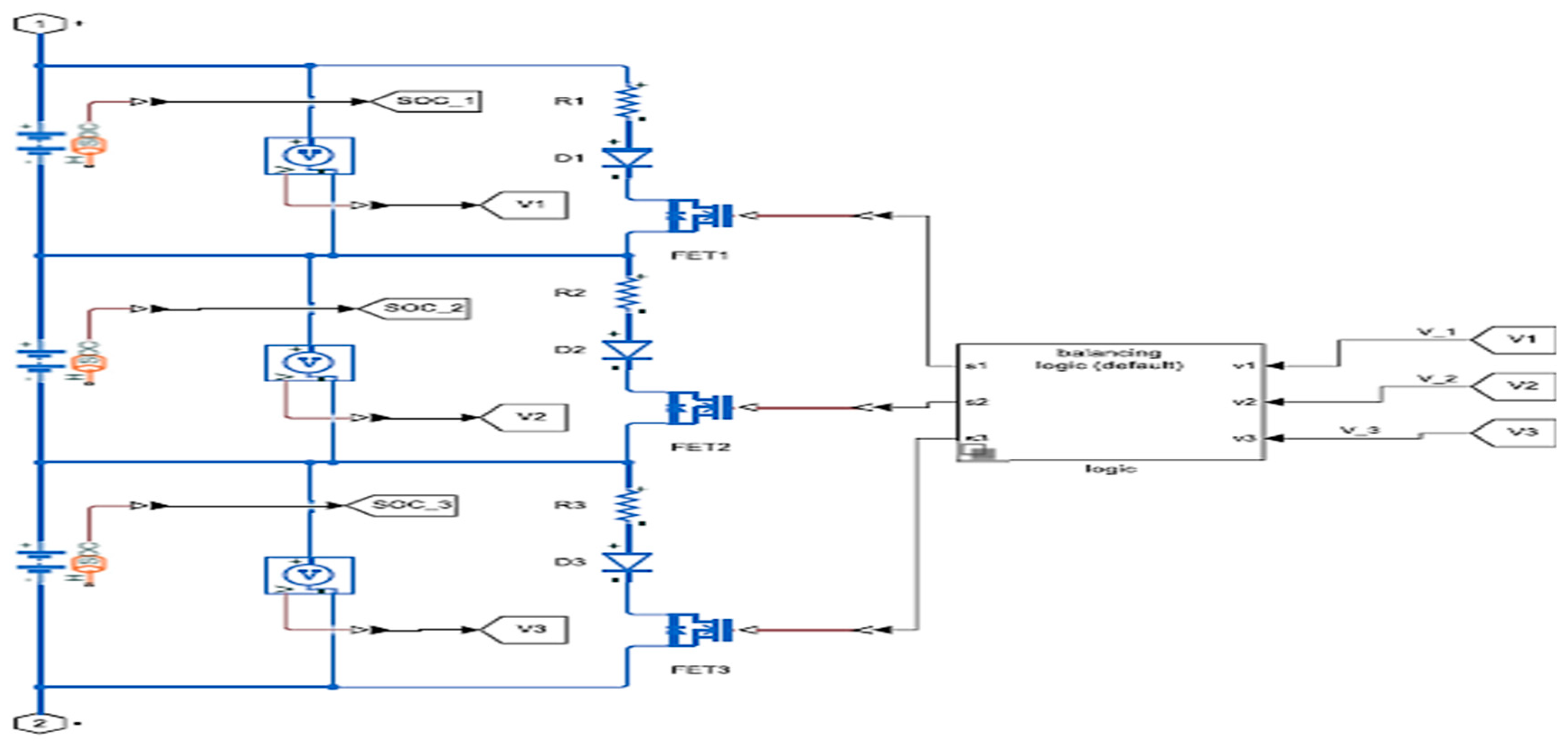
Passive balancing is the basic balancing techniques used earlier. It is the simplest balancing technique and uses additional load to balance the cells. Most common method of passive balancing is charge shuttling in which additional load (Resistor) is connected in parallel across each cell. Extra charge is dissipated in the form of heat through the shunt resistor connected in the parallel to the battery cell [
24]. It cannot be used for lithium-based batteries as there is a high risk of explosion [
25].
Figure 12.
Passive Balancing circuit.
Figure 12.
Passive Balancing circuit.
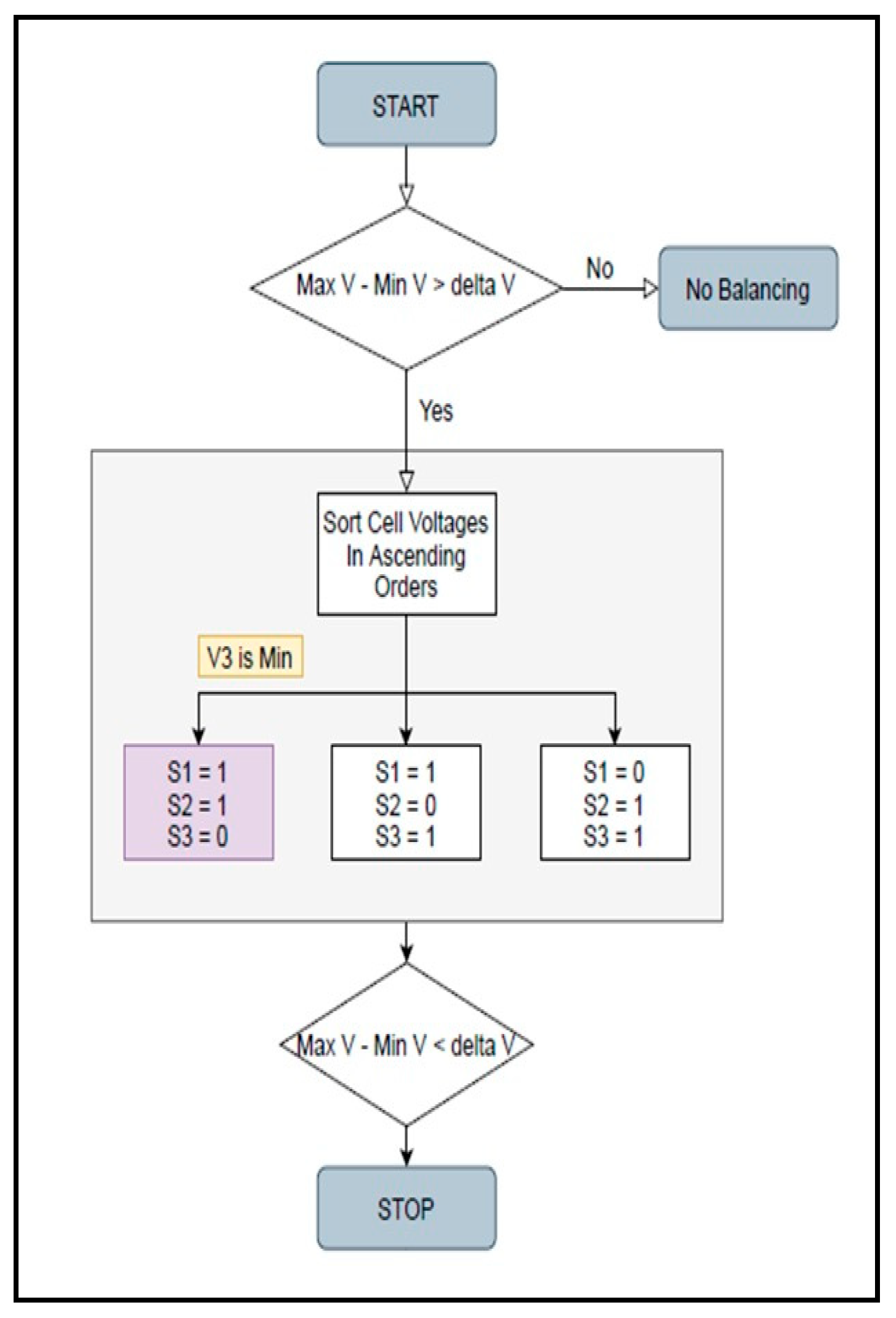
In state flow diagram, operations are carried out based on the current state of the system and based on the logic provided the system goes into the next state. This concept can be easily understood from the flow chart given in the
Figure 13.
System will be continuously monitoring the state of charge and voltage of each cell within the battery pack. When in the difference between the maximum Voltage and the minimum Voltage is greater than 2% its assumed that cells are imbalanced and balancing protocol will be executed ad system will go into balancing state. Now the system will monitor Voltage of each cell and based on the logic provided it will arrange the cell in ascending order on their voltages. From the flow chart above let’s assume that cell 1 has the lowest voltage (or say SOC) in this case other two cells should be discharged unless and until their SOC is equivalent to the third cell (approximate Error of 2%). For this to happen system will ON the switch 2 and switch 3 which will connect cell 1 and cell3 to shunt resistor which is connected in parallel to cell. The resistor will discharge the cell by giving out charge in form of heat. Meanwhile system will keep checking the SOC difference once the difference is below 2% balancing sequence will stop and all the MOSFET will on OFF state.
Based on the control logic explained in
Figure 13 a simulink model was developed in order to investigate the battery management system and it is shown in
Figure 14. A battery subsystem of that simulink is separately shown if
Figure 15.
3. Results and Discussion
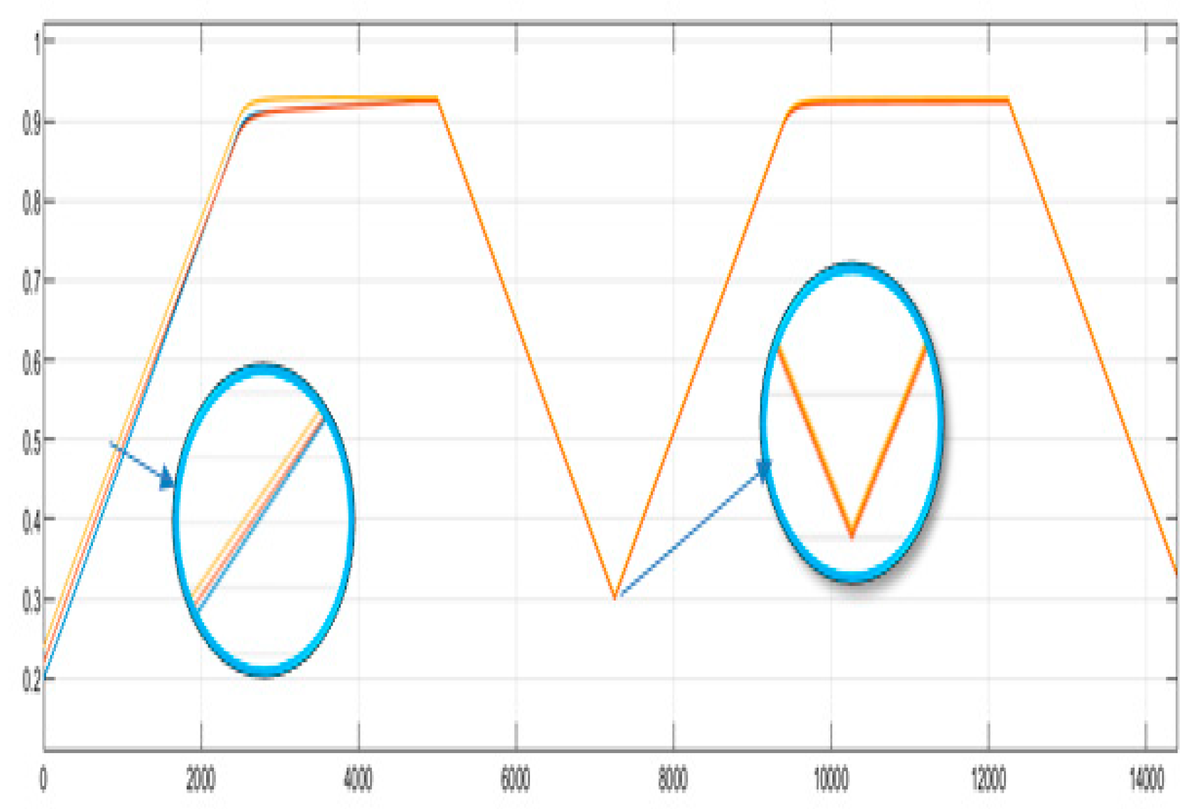
Based on the results obtained it can be seen from
Figure 16 that the time required for the balancing is 6000 seconds. Once the cells are being balanced based on the discharger logic battery will start to drain and cycle repeats for given time span.
Active Balancing Technique
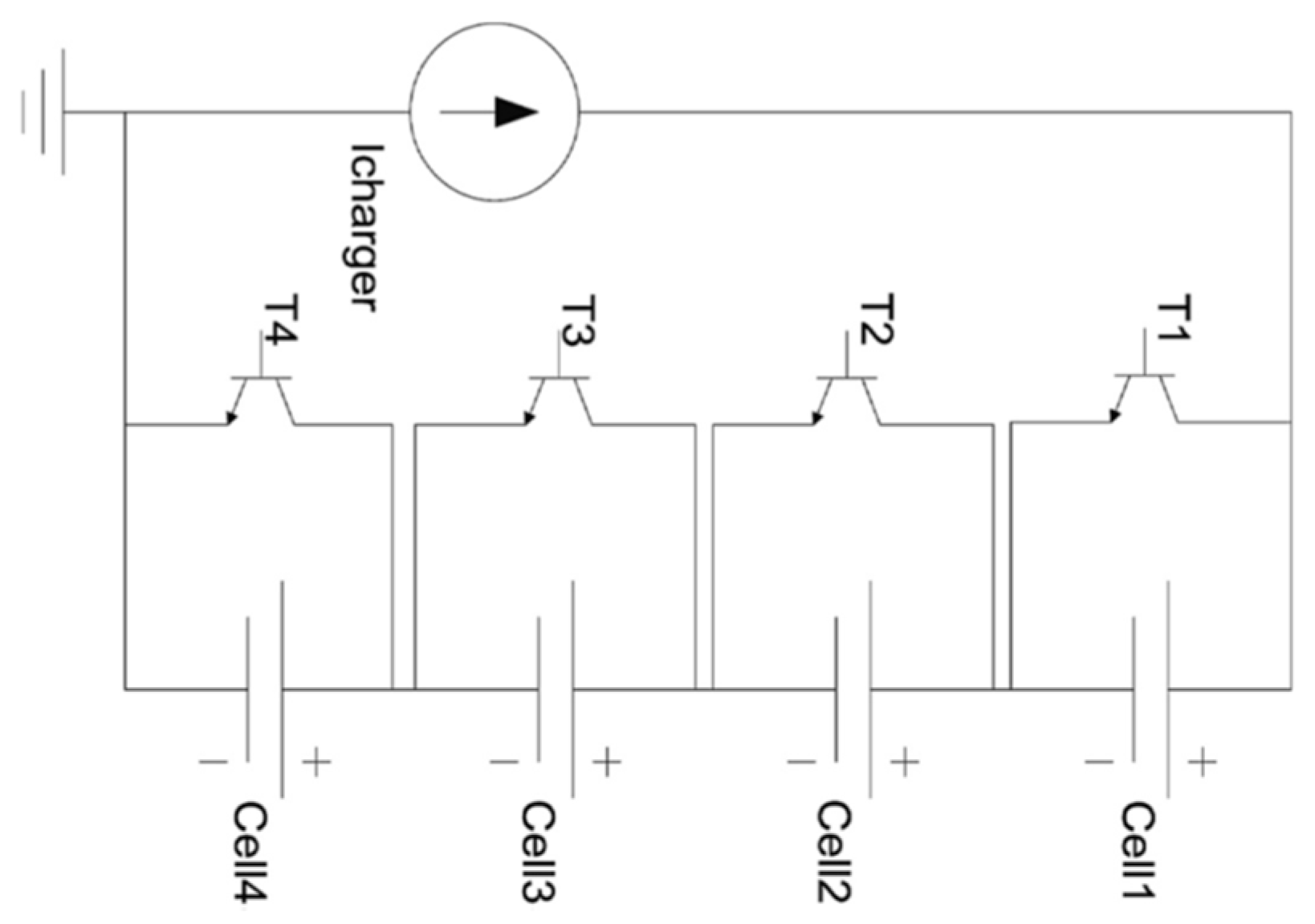
In case of Active balancing charge from higher voltage cell is transferred to some active energy storage devices such as capacitor and inductor and then form active device to the lower voltage cell. The time required for this type of balancing technique is very less compared to that of passive balancing technique and also helps to have continuous charging hence increasing the battery life.
One such active balancing technique is switched capacitor active balancing technique.
Figure 17.
Switched capacitor active balancing.
Figure 17.
Switched capacitor active balancing.
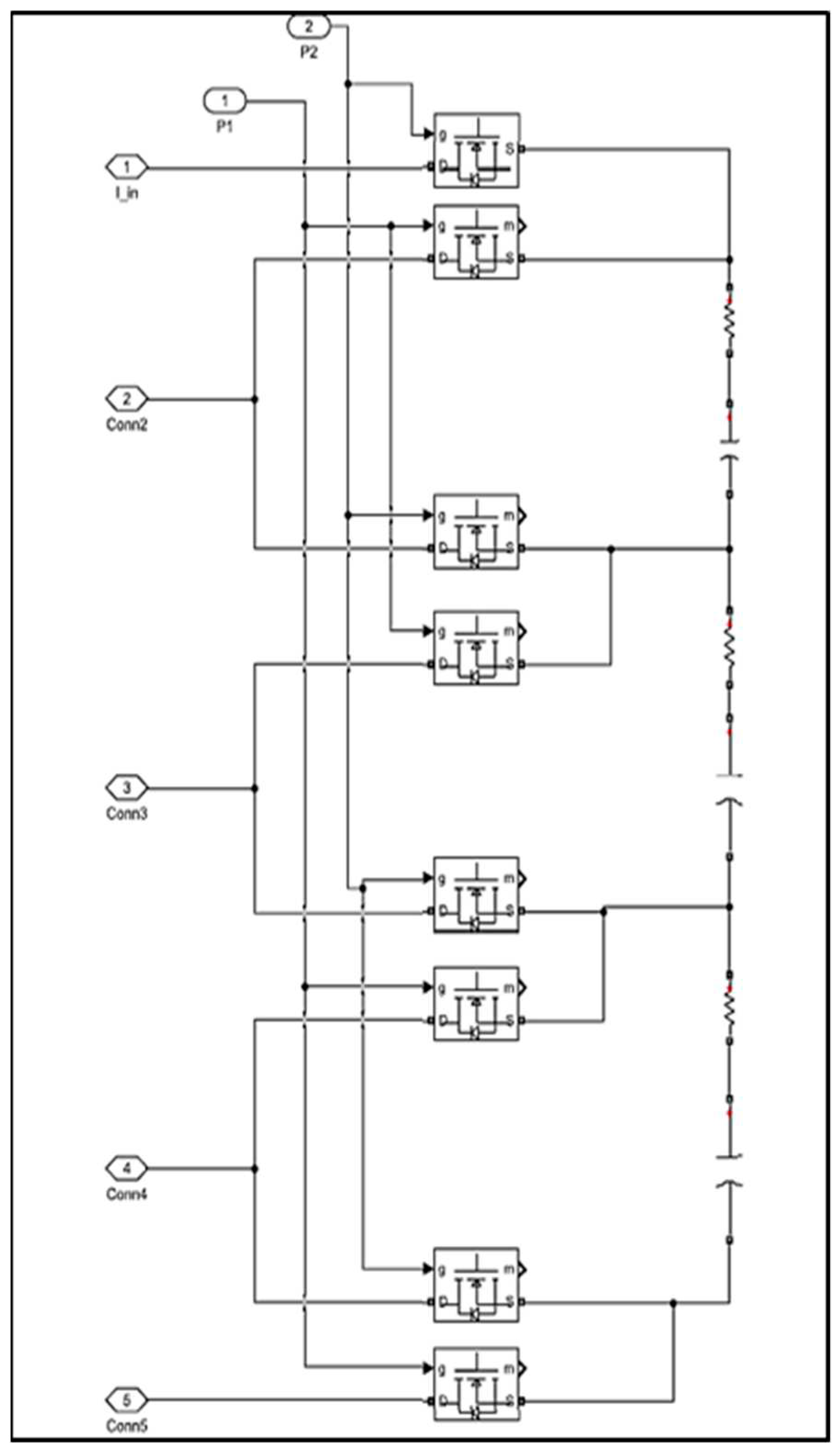
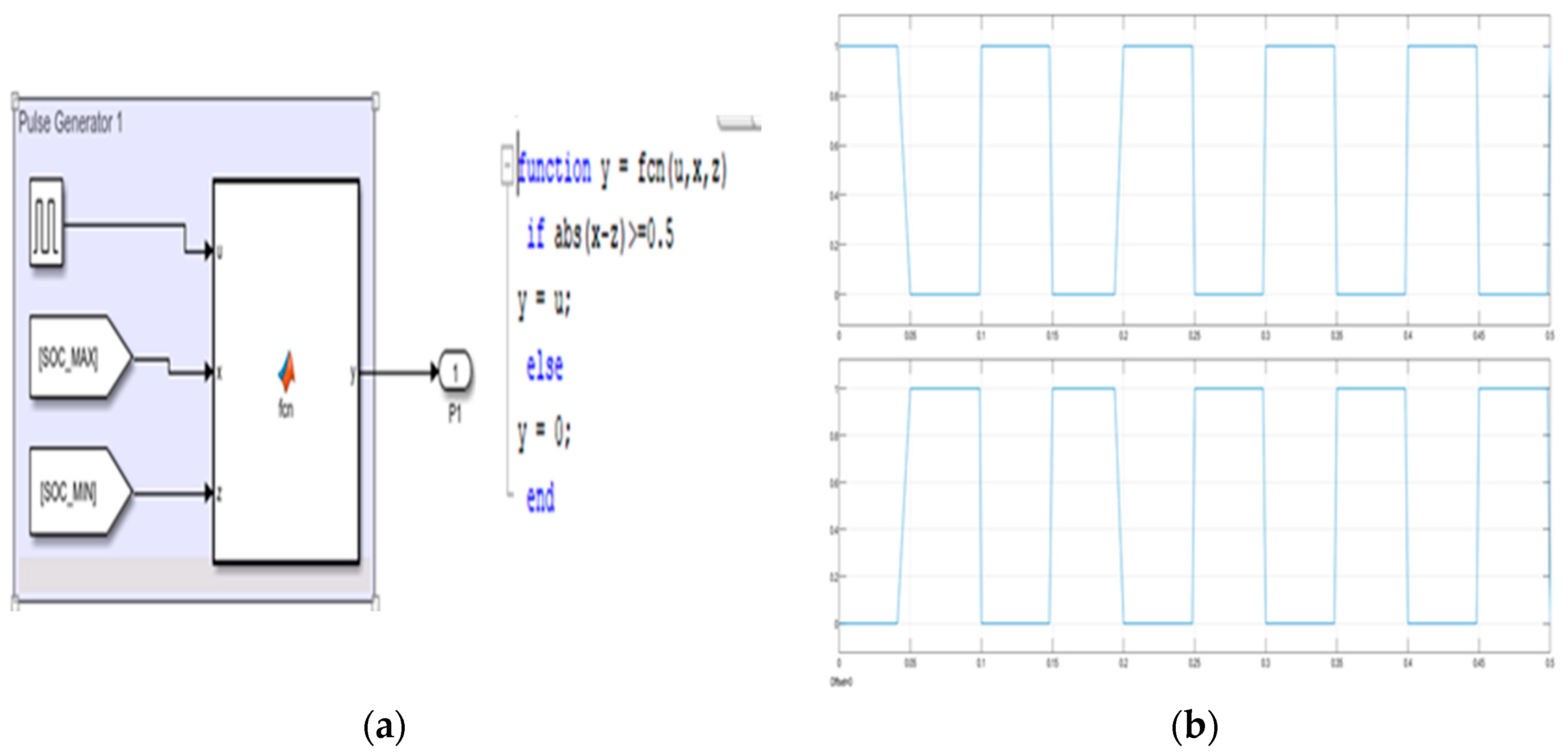
In this shuffling of the charge is done between capacitor and the battery cells using pulse generator and MOSFET switch. Pulse generators are provided with a control logic to initiate the balancing sequence. When the SOC difference is above 2% the balancing sequence will initiate during which at MOSFET switching will take place at very high frequency. We will be using two pulse generators generating pulses with 50% phase delay due to which MOSFET will switch in an alternate form i.e. when on MOSFET is one other will be in the off condition. Due to this capacitor will get charged by first pulse generator and will get discharged when the second pulse generator is connected. Above process will continue till the SOC Drop is not below 2%. Once it is then the balancing sequence will terminate and regular charging cycle will continue. It has to be noted that during balancing sequence battery won’t be in charging state rather it will discharge the cell voltage and charge the cell with lower voltage.
Below relation will give the charge that is been stored in the capacitor and that is been transferred to the cell with lower voltage. Once each capacitor has reached its corresponding upper cell voltage (V
ui), the stored charge (Q
ci) for the i-capacitor is
Each switching cycle, the i-capacitor transfers the current I
ci from the most charged adjacent cell to the least charged adjacent cell according to
Where is the lower cell voltage of the i-capacitor, fsw is the switching frequency.
Therefore, the capacitor behaves like a resistance and the equivalent resistance R
c is
By taking into account the on-resistance of the switches (Rsw), the total resistance for the i-capacitor (R
swi) is
Where D is the duty cycle.
The efficiency degradation per capacitor follows
Figure 18.
Simulink model for switched capacitor system.
Figure 18.
Simulink model for switched capacitor system.
Input form the pulse generator as shown in
Figure 19. is given to MOSFET. Based on the requirement and balancing speed we can change the switching frequency using PWM-DC-DC-Converter.
The parameters and their values of balancing unit are provided in the
Table 4 and the battery pack parametrs are shown in
Table 5.
Figure 20.
Control circuit.
Figure 20.
Control circuit.
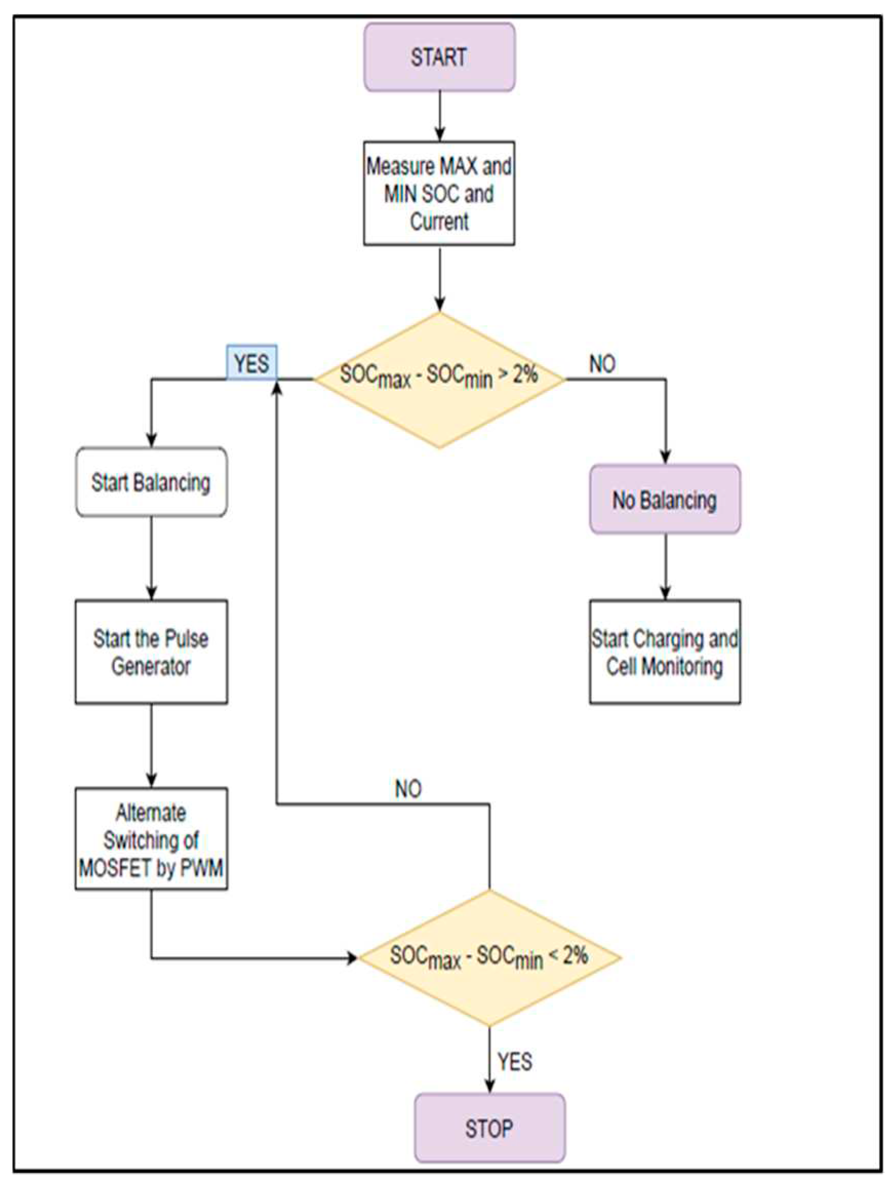
Switched capacitor balancing can also be termed as automatic balancing technique. Flow chart in
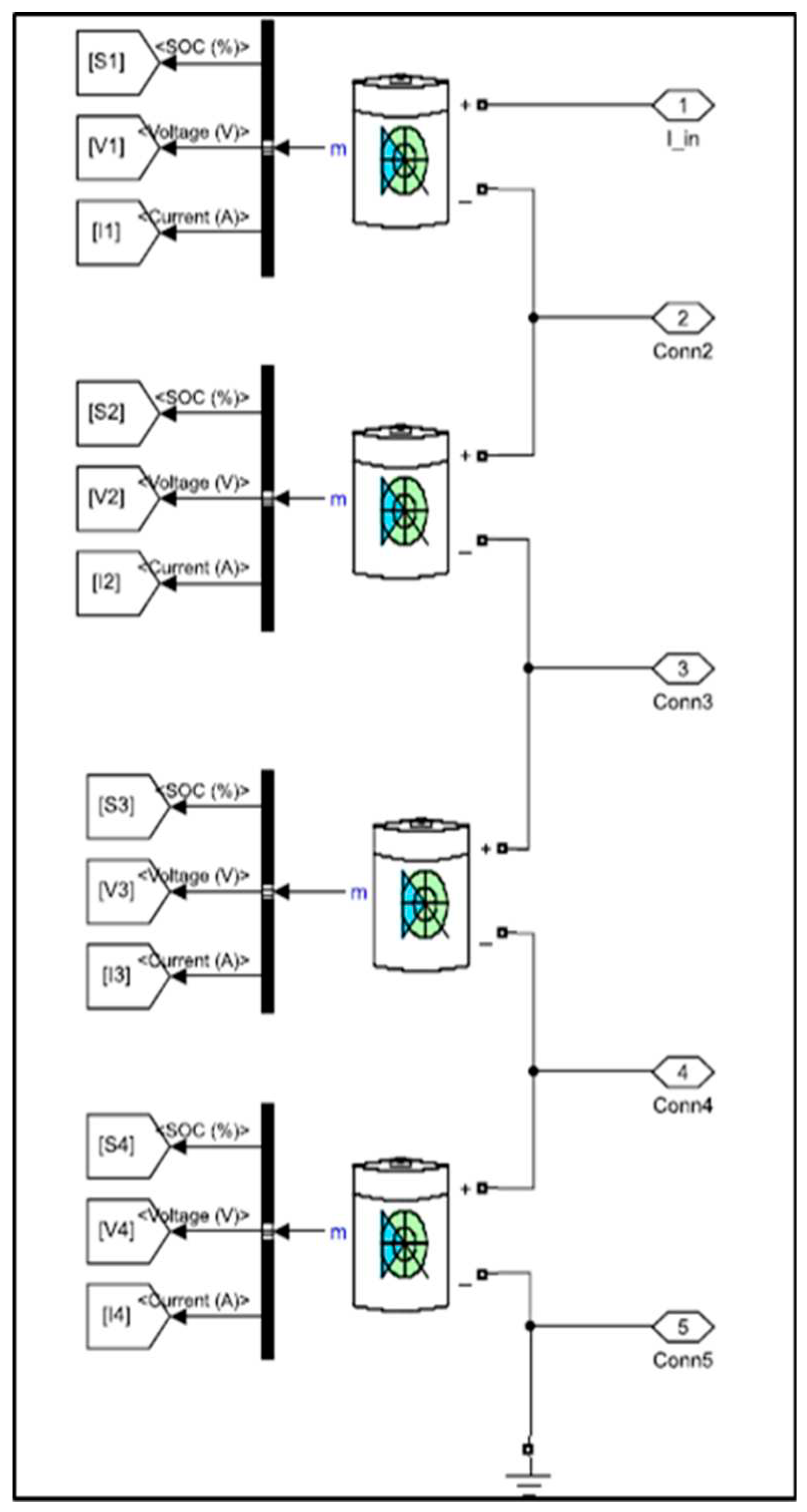
Figure 22 gives us the basic idea about how the balancing takes place. Initially system will measure for the maximum and minimum SOC of each cell and it will get the difference between the maximum and minimum SOCs. If the difference is turned out to be more than 2% then charger will get disconnected and active balancing take place. MOSFET switches are connected in such a manner that if cell 1 discharges then cell 2 will get charged by the charge that is been discharged by the cell 1. Further the discharged charge is also stored in the capacitor connected in parallel across each pair of cells. Charge will be transferred to the cell with lower charge. The pulse generate will generate two type of pulses with 50% phase delay in the next pulse by doing so alternate switching will take place. This will continue unless charge is balanced in each of adjacent cells. Once the cells are balanced the charger will be connected and cycle will continue further.
Figure 21.
Battery pack design.
Figure 21.
Battery pack design.
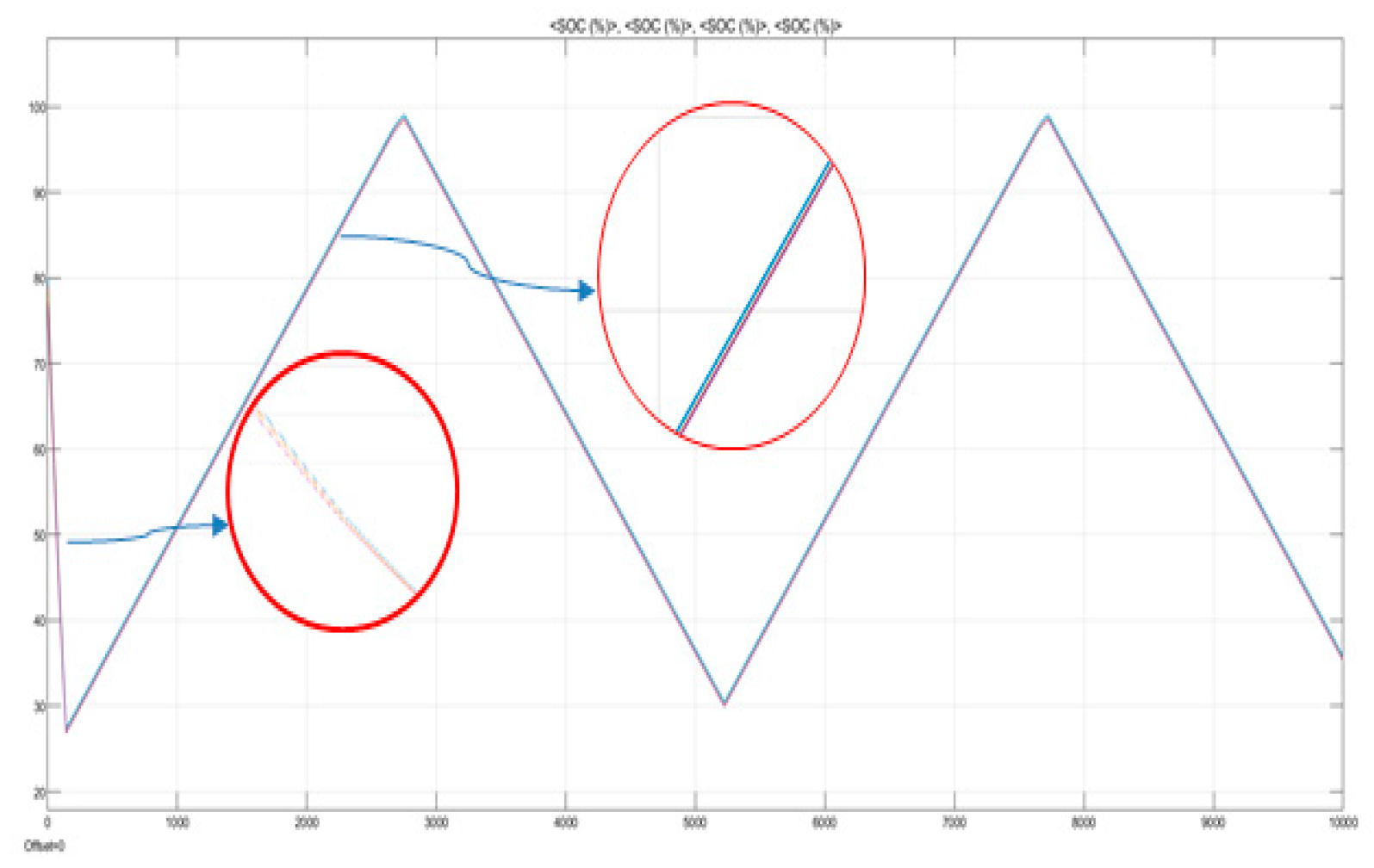
Based on the results obtained it can be observed that the time required for cell balancing is around 140 seconds as seen in
Figure 23. During cell balancing cell will undergo in discharge state unless the cells get balanced once they are balanced the cycle will to charging state.
4. Conclusions
It is very important for BMS to be well-maintained for battery reliability and safety, proper state monitoring and evaluation, and functional cell balancing and charge control. Due to these reasons, there is a need for BMS optimization for EVs to increase the reliability of BMS and optimize EVs power performance. From this paper, we can conclude with following points
Balancing time required in case of passive balancing was 4500 seconds whereas that in case of active balancing was 140 seconds.
Active balancing was continuous whereas passive balancing was not continuous and time taken at higher SOC is very high.
Costing of passive balancing could be very high for larger battery pack and cost does not justify with the balancing time required.
By adopting different active balancing techniques and different control logics we can further reduce the balancing time and hence increase the overall life and performance of the battery pack.
References
- Emadi, Y l Lee, and K. Rajashekara, "Power electronics and motor drives in electric, hybrid electric, and plug-in hybrid electric vehicles," IEEE Trans. Ind. Electron, vol. 55. pp. 2237- 2245, June 2008. [CrossRef]
- Stuart A., T. , and Zhu W., “Fast Equalization for Large Lithium-Ion Batteries”, IEEE Aerospace and Electronic Systems Magazine, Vol. 24, pp. 27-31, 2009. [CrossRef]
- Zhang, X. , Liu P., and Wang D., “The Design and Implementation of Smart Battery Management System Balance Technology”, J. Convergence Information Technology, Vol. 6, No. 5, pp. 108-116, May 2011. [CrossRef]
- Cao, J. , Schofield N., and Emadi A., “Battery balancing methods: A comprehensive review”, IEEE Vehicle Power and Propulsion Conf., VPPC08, pp. 1-6, 2008. [CrossRef]
- Daowd, M. , Omar N., Van Den Bossche P., and Van Mierlo J., “Passive and active battery balancing comparison based on MATLAB simulation”, IEEE Vehicle Power and Propulsion Conf., VPPC 2011, pp. 1-7, 6-9 Sept. 2011. [CrossRef]
- Kutkut N., H. , Wiegman H., Divan D. M. and Novotny D. W., “Design considerations for charge equalization of an electric vehicle battery system”, IEEE Trans. Industry Applications, 35(1), Jan. 1999. [CrossRef]
- Moore, S. and Schneider, P., “A Review of Cell Equalization Methods for Lithium-Ion and Lithium Polymer Battery Systems,” SAE Technical Paper 2001-01-0959, 2001. [CrossRef]
- West, S. , and Krein P. T., “Switched-Capacitor Systems for Battery Equalization”, IEEE Modern Techniques and Technology (MTT 2000). Proceedings of the VI International Scientific and Practical Conference of Students, Post-graduates and Young Scientists, pp. 5759, 2000. [CrossRef]
- Pascual, C. , and Krein P. T., “Switched-Capacitor System for Automatic Series Battery Equalization”, IEEE Applied Power Electronics Conf. and Expo., pp. 848-854, 1997. [CrossRef]
- Baughman A., C. , and Ferdowsi M., “Double-Tiered Switched- Capacitor Battery Charge Equalization Technique”, IEEE Trans. Industrial Electronics, Vol. 55. pp. 2277-2285, 2008. [CrossRef]
- Sang-Hyun, P. , Tae-Sung K., Jin-Sik P., Gun-woo M., and Myung-Joong Y., “A New Battery Equalizer Based on Buck-boost Topology,” IEEE 7th Int'l Conf. Power Electronics, pp. 962-965, 2007. [CrossRef]
- Cioroianu, Constantin Cristian, et al. "Simulation of an electric vehicle model on the new WLTC test cycle using AVL CRUISE software." IOP Conference Series: Materials Science and Engineering. Vol. 252. No. 1. IOP Publishing, 2017. [CrossRef]
- Jin, Li-qiang, et al. "A study of novel regenerative braking system based on supercapacitor for electric vehicle driven by in-wheel motors." Advances in Mechanical Engineering 7.3 (2015). [CrossRef]
- Ilimbetov, R. Yu, V. V. Popov, and A. G. Vozmilov. "Comparative Analysis of “NGTU–Electro” Electric Car Movement Processes Modeling in MATLAB Simulink and AVL Cruise Software." Procedia Engineering 129 (2015): 879-885.
- Yang, Yajuan, Han Zhao, and Hao Jiang. "Drive train design and modeling of a parallel diesel hybrid electric bus based on AVL/Cruise." World Electric Vehicle Journal 4.1 (2010): 75-81. [CrossRef]
- Iclodean, C. , et al. "Comparison of different battery types for electric vehicles." IOP conference series: materials science and engineering. Vol. 252. No. 1. IOP Publishing, 2017. [CrossRef]
- Omariba, Zachary Bosire, Lijun Zhang, and Dongbai Sun. "Review of Battery Cell Balancing Methodologies for Optimizing Battery Pack Performance in Electric Vehicles." IEEE Access 7 (2019). [CrossRef]
- Capron, J. Jaguemont, R. Gopalakrishnan, P. van dem Bossche, N. Omar, and J.vanMierlo, ‘‘Impact of the temperature in the evaluation of battery performances during long-term cycling–Characterisation and modelling,’’ Appl. Sci., vol. 8, no. 8, p. 1364, 2018. [CrossRef]
- V. Mueller, R. Kaiser, S. Poller, D. Sauerteig, R. Schwarz, M. Wenger, V. R. H. Lorentz, and M. Maerz, ‘‘Introduction and application of formation methods based on serial-connected lithium-ion battery cells,’’ J. Energy Storage, vol. 14, pp. 56–61, Dec. 2017. [CrossRef]
- J. Gallardo-Lozano, E. Romero-Cadaval, M. I. Milanes-Montero, and M. A. Guerrero-Martinez, ‘‘Battery equalization active methods,’’ J. Power Sources, vol. 246, pp. 934–949, Jan. 2014. [CrossRef]
- Ye, Yuanmao, and Ka Wai Eric Cheng. "An automatic switched-capacitor cell balancing circuit for series-connected battery strings." Energies 9.3 (2016): 138. [CrossRef]
- Kim, Moon-Young, et al. "Switched capacitor with a chain structure for cell-balancing of lithium-ion batteries." IECON 2012-38th Annual Conference on IEEE Industrial Electronics Society. IEEE, 2012. [CrossRef]
- Ye, Yuanmao, and Ka Wai Eric Cheng. "An automatic switched-capacitor cell balancing circuit for series-connected battery strings." Energies 9.3 (2016): 138. [CrossRef]
- Manenti, A. , Abba, A., Geraci, A., & Savaresi, S. (2011). A new cell balancing architecture for Li-ion battery packs based on cell redundancy. IFAC Proceedings Volumes, 44(1), 12150-12155. [CrossRef]
- Daowd, Mohamed, et al. "Battery management system-Balancing modularization based on a single switched capacitor and bi-directional DC/DC converter with the auxiliary battery." Energies 7.5 (2014): 2897-2937. [CrossRef]
- A.R. Sibiceanu, A. Iorga, V. Nicolae, F. Ivan, Consideration on the Implications of the WLTC (Worldwide Harmonized Light-Duty Test Cycle) for a Middle-Class Car, CONAT Brașov ISSN 2069-0401, Transilvania University Press, pp 203-211, 2016.
|
Disclaimer/Publisher’s Note: The statements, opinions and data contained in all publications are solely those of the individual author(s) and contributor(s) and not of MDPI and/or the editor(s). MDPI and/or the editor(s) disclaim responsibility for any injury to people or property resulting from any ideas, methods, instructions or products referred to in the content. |
© 2023 by the authors. Licensee MDPI, Basel, Switzerland. This article is an open access article distributed under the terms and conditions of the Creative Commons Attribution (CC BY) license (http://creativecommons.org/licenses/by/4.0/).
