1. Introduction
Benefiting from advantages that include high resolution, fast response times, and high bandwidths [
1,
2,
3], piezoelectric actuators (PZAs) are used widely in high-precision instruments for applications in aerospace, precision machining, semiconductor technology, and other fields [
4]. To allow the advantages offered by PZAs to be used fully, the compliant amplifying mechanism, which plays an important role in piezoelectric stroke amplification, has attracted considerable attention in recent years. Given that the finite element method (FEM) fails to reflect the internal mechanism or the effects of the geometric parameters of flexible amplifying mechanisms, it has thus become necessary to develop a suitable model that is both static and dynamic.
Investigations have shown that research on static modeling of the compliant amplifying mechanism has attracted a great deal of attention, and the methods used[
5] mainly include Castigliano’s second theorem[
2,
6,
7,
8,
9], Flexibility Matrix Method [
10,
11,
12,
13,
14,
15], matrix displacement method[
1,
16,
17], elastic beam theory [
18,
19,
20,
21,
22,
23] and kinematics principles [
22,
24,
25,
26,
27,
28]. Based on these methods, the effects of the main parameters of the mechanism on its static characteristics have been analyzed, and the relationship between the input and output displacements of the mechanism was established. Dynamic modeling methods have mostly involved use of the Lagrange equation[
9,
11,
14,
28,
29,
30,
31], and part of the analysis was performed according to d’Alembert’s principle in combination with the matrix displacement method[
1,
17]. Further analysis showed that most of the static analysis efforts have focused on modeling of the flexible bridge arm, and modeling of the piezoelectric actuators and the effects of their pseudo-rigid units on the properties of the mechanism have not been considered fully. The dynamic modeling analyses are mainly concerned with analysis of the mechanism carrier, while no specific analysis has been performed to address the effects of the main geometric parameters on the mechanism. More importantly, there are very few unified analysis models of compliant amplifying mechanisms that include both dynamic and static analyses.
Therefore, the work presented in this paper established a theoretical mathematical model of the amplifying mechanism using the multi-body system transfer matrix method (MSTMM). The effects of the main parameters of the mechanism (including the thickness, angle, and width of the bridge arm, the length, width, and height of the pseudo-rigid body units, and the material properties of the mechanism) on its dynamic and static characteristics were analyzed using the control variable method. Furthermore, an iterative optimization algorithm was used to obtain specific parameters that meet the mechanism’s design requirements.
The rest of this paper is organized as follows. In
Section 2, the process in which the mathematical model of the amplifying mechanism is established using the transfer matrix method is described. In
Section 3, the mechanism’s static characteristics are analyzed. In
Section 4, the mechanism’s dynamic characteristics are analyzed. In
Section 5, a modified transfer matrix is established to reduce the error caused by the stress concentration. In
Section 6, the process used to determine the optimal values that meet the design requirements of the mechanism is introduced. In
Section 7, the proposed model is simulated and the mechanism is designed and verified experimentally. In
Section 8, the proposed method is applied to practical situations and experiments are performed. Conclusions about the study are presented in the final section.
2. The Mathematical Models Based on MSTMM
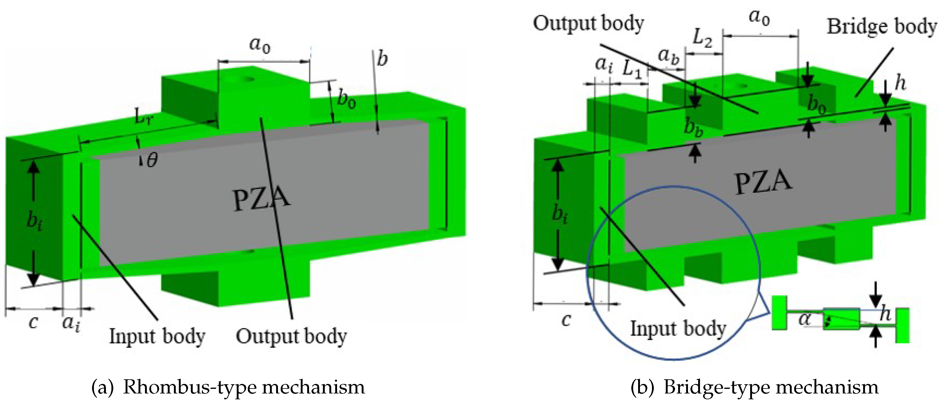
Common basic compliant amplifying mechanism models include both rhombus-type and bridge-type compliant mechanism models. The rhombus-type compliant mechanism is the simplest model in terms of the triangular amplification principle, offering high operating frequencies and strong load capacities[
32]. Additionally, the bridge-type compliant mechanism can be regarded as a special rhombus-type compliant mechanism that has a compact structure and a large displacement amplification ratio. Schematic diagrams showing the main geometric parameters of the rhombus-type and bridge-type compliant mechanisms are presented in
Figure 1. The flexible mechanism is driven using a piezoelectric actuator. When this piezoelectric actuator is elongated laterally, the compliant mechanism produces longitudinal deformation and an output displacement under the action of an input force/displacement.
Using the MSTMM[
33,
34,
35,
36],the rhombus-type and bridge-type compliant mechanisms can be divided into units, as shown in
Figure 2. The rhombus-type compliant mechanism is divided into pseudo-rigid units 1, 3, 5, 7, 9, and 11, flexible units 2, 4, 6, and 8, and piezoelectric unit 10 (see
Figure 2(a)). Similarly, the bridge-type compliant mechanism can be divided into pseudo-rigid units 1, 3, 5, 7, 9, 11, 13, 15, 17, and 19, flexible units 2, 4, 6, 8, 10, 12, 14, and 16, and piezoelectric unit 18 (see
Figure 2(b)).
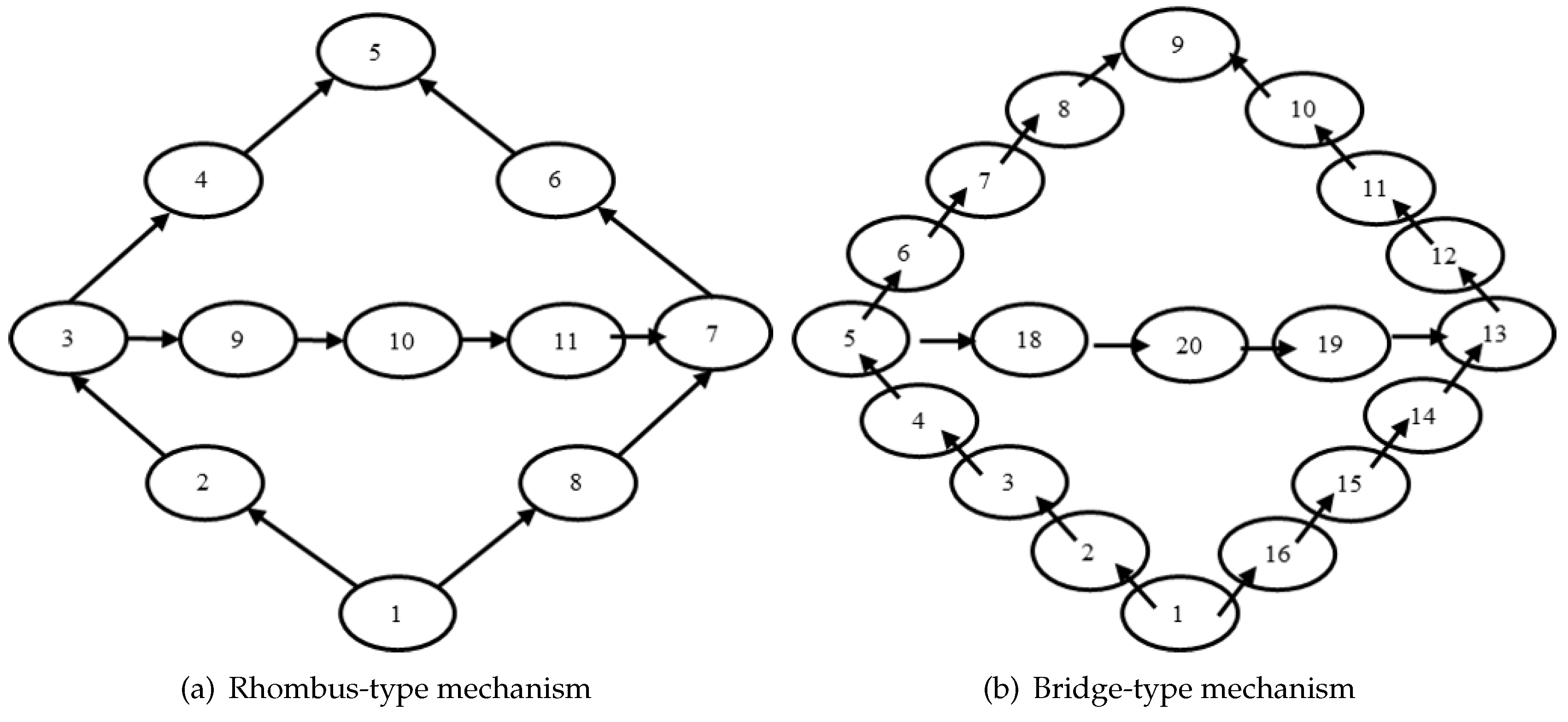
When the transmission route of the system is established, it can be seen that the amplifying mechanism becomes a bifurcation mechanism, and its transmission route is no longer unique. The topological relationship diagram of the amplifying mechanism is shown in
Figure 3 and indicates the interrelationships between the units. The local coordinate systems corresponding to each unit are shown in
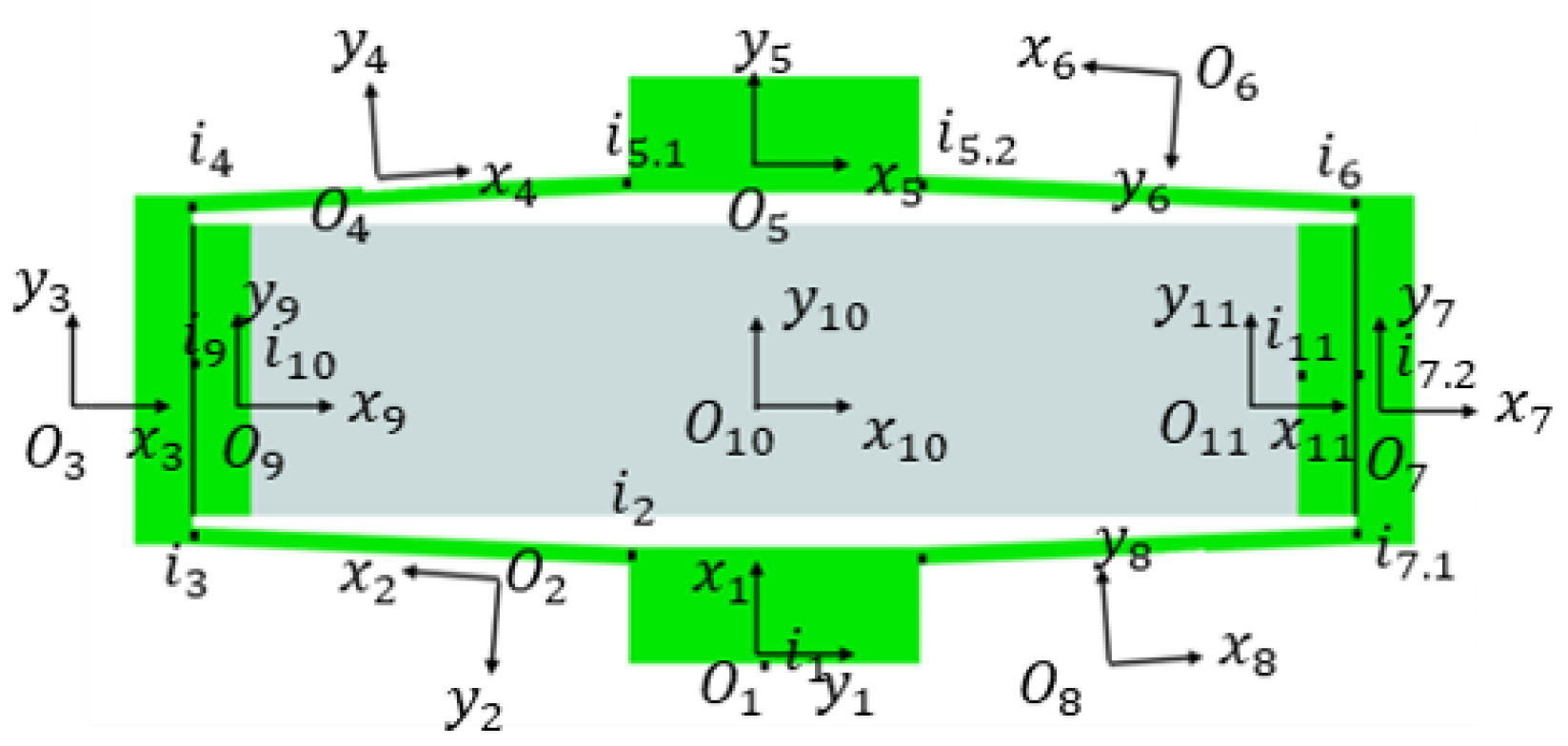
Figure 4.
In
Figure 4,
is the input point of the i-th unit(
), and
and
are the first and second input points of the i-th unit(i=5,7), respectively. The local coordinate system in the area where the unit is located is established by using the input point as the origin. The local coordinate system
is inconsistent with the global coordinate directions, and the corresponding coordinate changes are shown during the calculations.
Based on consideration of the need for both static and dynamic analysis of the mechanism, an extended transfer matrix should be established here. With reference to the literature [
37], the equation for the transfer matrix of the piezoelectric actuator was derived, and the transfer matrix for the piezoelectric actuator in the longitudinal direction is:
The equation above for the piezoelectric actuator’s longitudinal vibration is the same as that for the mass Euler beam. At the same time, when the lateral vibration of the piezoelectric actuator is considered, it can be regarded as a mass Euler-Bernoulli beam with ordinary elastic deformation. Therefore, the piezoelectric actuator can be regarded as a mass Euler-Bernoulli beam as a whole and the transfer matrix is the same as that for the beam. Addition of piezoelectric motion and force characteristics to the equation allows the total transfer expansion matrix of the piezoelectric actuator to be obtained as follows:
, ,and is the piezoelectric deformation coefficient.In addition, n is the number of piezoelectric ceramic pieces and is the driving voltage.
Then, based on the sub-transfer equation, the total transfer equation for the amplifying mechanism is established as shown.
Finally, the equation processing is performed.
3. Static Characteristic Analysis
The displacement amplification ratio is the main static characteristic of the compliant amplifying mechanism. To solve it, the compliant mechanism is in a quasi-static condition, that is, the frequency or .
By substituting for the appropriate parameters, the displacement amplification ratio of the mechanism can be calculated based on the mathematical model established using the MSTMM.
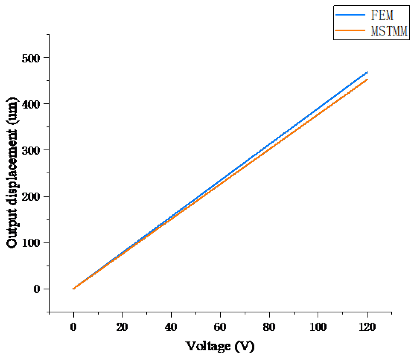
Figure 5 shows the output displacement characteristics of the amplifying mechanism versus the different voltages applied to the piezoelectric actuator as determined using the MSTMM and the FEM. The slope of the curve
indicates that the static characteristics of the amplifying mechanism are unaffected by changes in the input displacement[
12,
25]. These two curves are obviously similar and their variation trends are also comparable, which indicates that the mathematical model of the amplifying mechanism established based on the MSTMM can feasibly be used to describe the mechanism’s static characteristics.
(1) Flexible unit
To study the amplification ratio characteristics of the amplifying mechanism in greater depth, the effects of the different parameters on the output displacement amplification ratio of the mechanism are determined via the method of controlling variables.
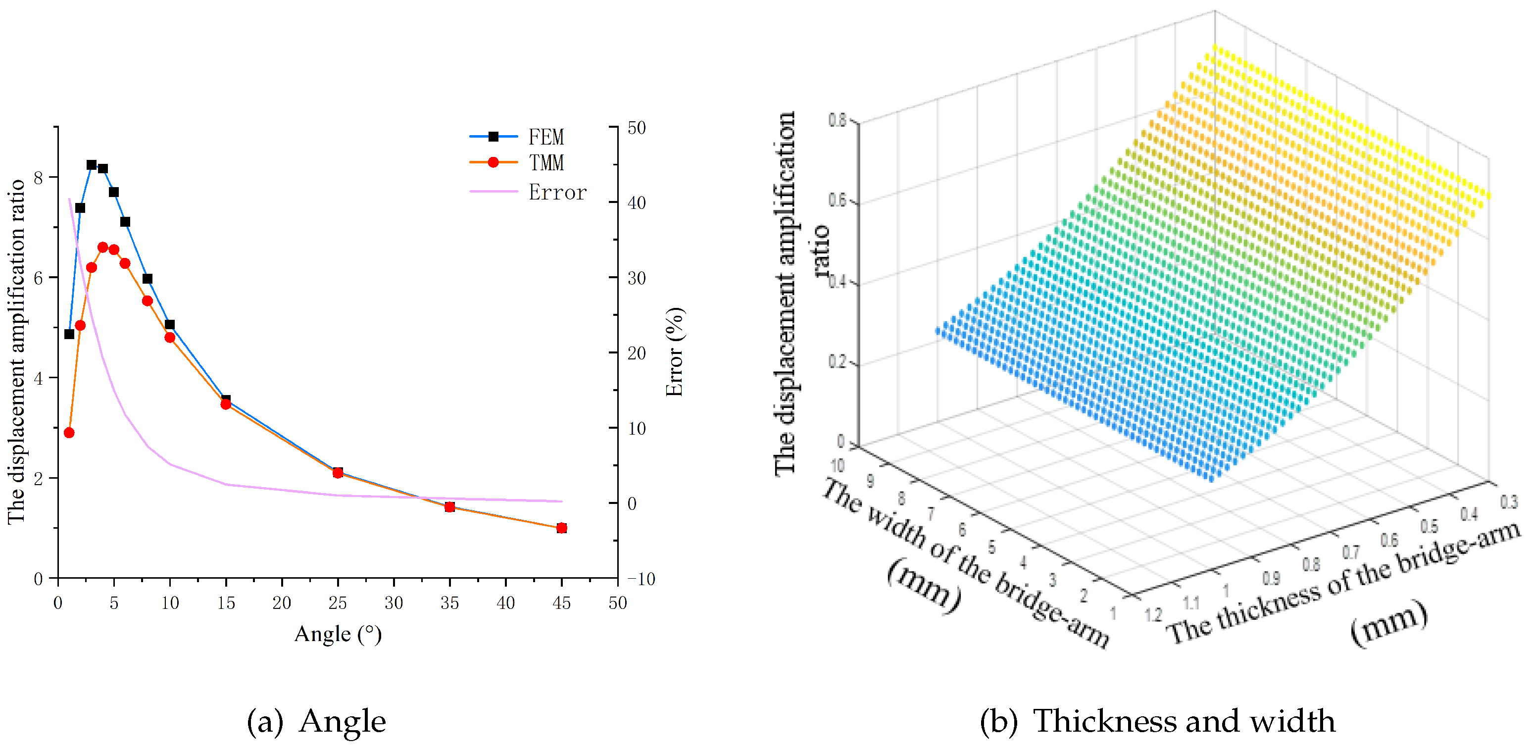
Figure 6(a) shows the relationship between the rhombus-type compliant mechanism’s amplification ratio and the bridge arm angle when the FEM results are compared with the MSTMM results. The figure shows that the two methods have similar trends, in that the amplification ratio increases initially and subsequently decreases with increasing bridge arm angle, which is consistent with the previous description in the literature[
38].Furthermore, the relative error between the two models decreases sharply as the angle increases, before gradually stabilizing after 15
.
Figure 6(b) shows that the amplification ratio of the rhombus-type mechanism decreases as the thickness of the bridge arm increases, but also shows that the ratio is not affected by the width of the bridge arm, which is consistent with the behavior described in the Qi’s article[
22].
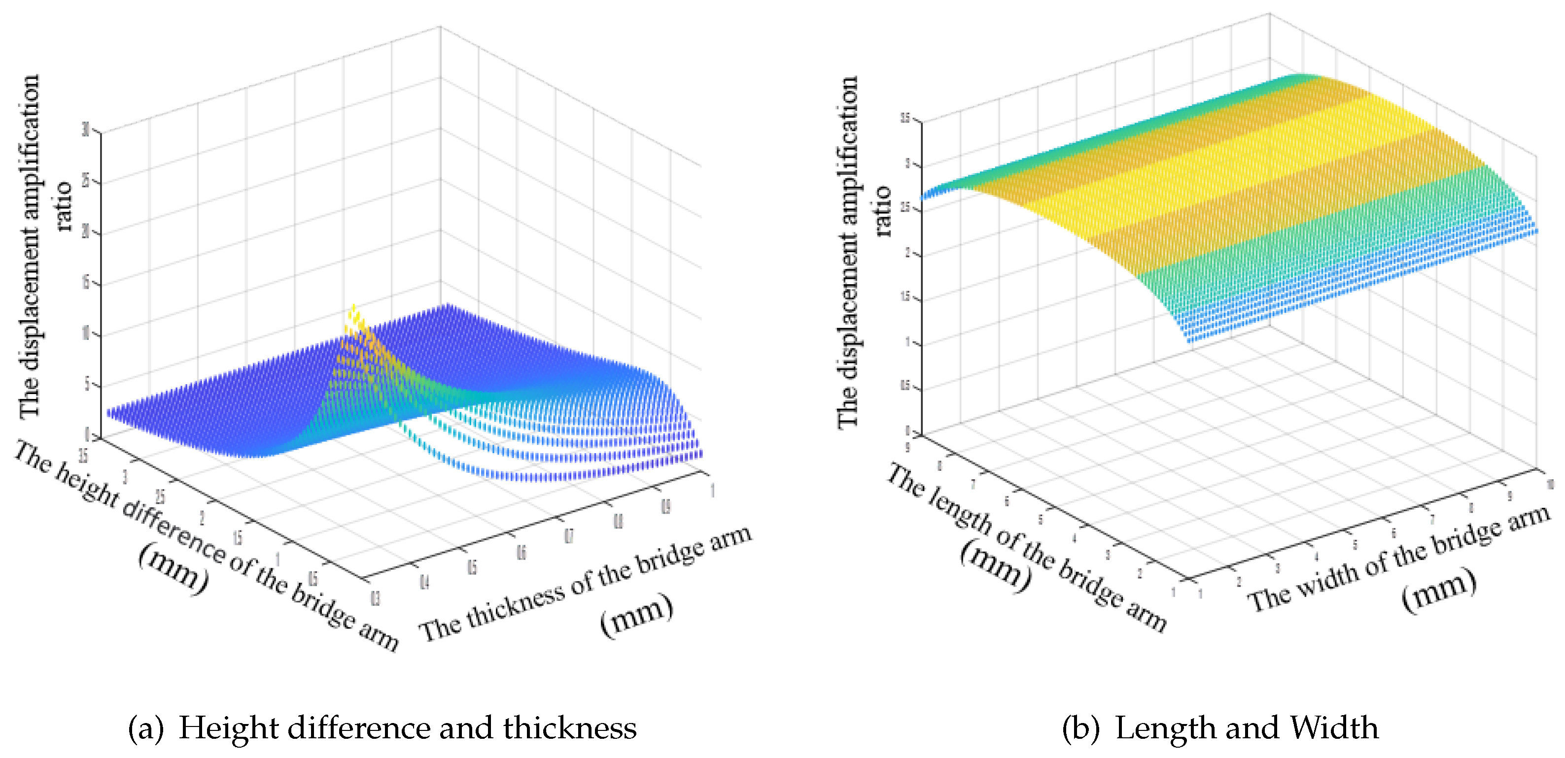
Figure 7 shows the effects of the bridge arm parameters of the bridge-type amplifying mechanism on its static characteristics.
Figure 7(a) shows that the effects of the main parameters of the mechanism on the amplification ratio of the bridge mechanism are consistent with those of the rhombus mechanism[
22]. The only difference is that in the bridge-type mechanism, the angle in the rhombus mechanism is replaced with the height difference between the two bridge arms, which means that the main parameters also include the lengths of the two sub-bridge arms (
). The results show that the amplification ratio reaches a maximum when the sub-bridge arms are equal in length (see
Figure 7(b)).
(2) Pseudo rigid body element
Unlike many other reports in the literature, which focused on studies of the bridge arm, this paper also studies the effects of the parameters of the pseudo-rigid body units on the mechanism’s amplification ratio.
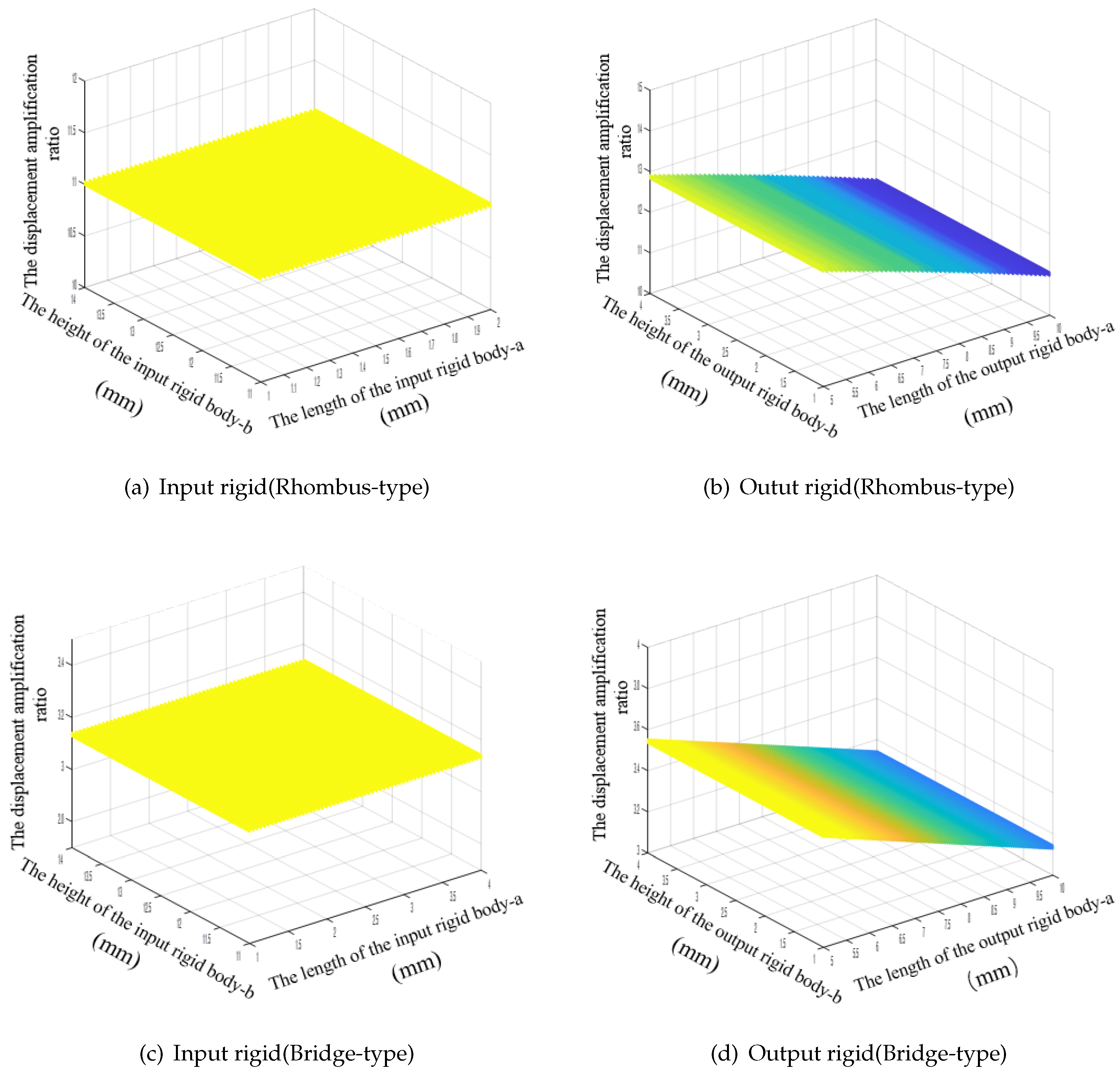
Figure 8 shows that the length and the height of the input rigid body unit and the height of the output rigid body do not affect the mechanism’s amplification ratio. The only parameter that affects the amplification ratio is the length of the bridge arm. The amplification ratio is affected obviously when the bridge arm length is changed. When the length of the output rigid body increases, the length of the bridge arm becomes shorter, and the amplification ratio of the mechanism decreases.
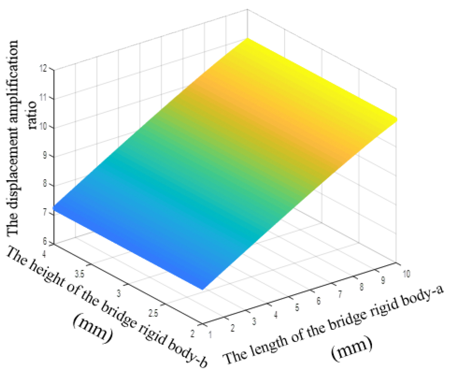
Figure 9 shows that the magnification ratio of the bridge amplifying mechanism increases as the length of the rigid body of the bridge arm increases (i.e., with increasing bridge arm length), and that the ratio has nothing to do with the arm width.
(3) Material properties
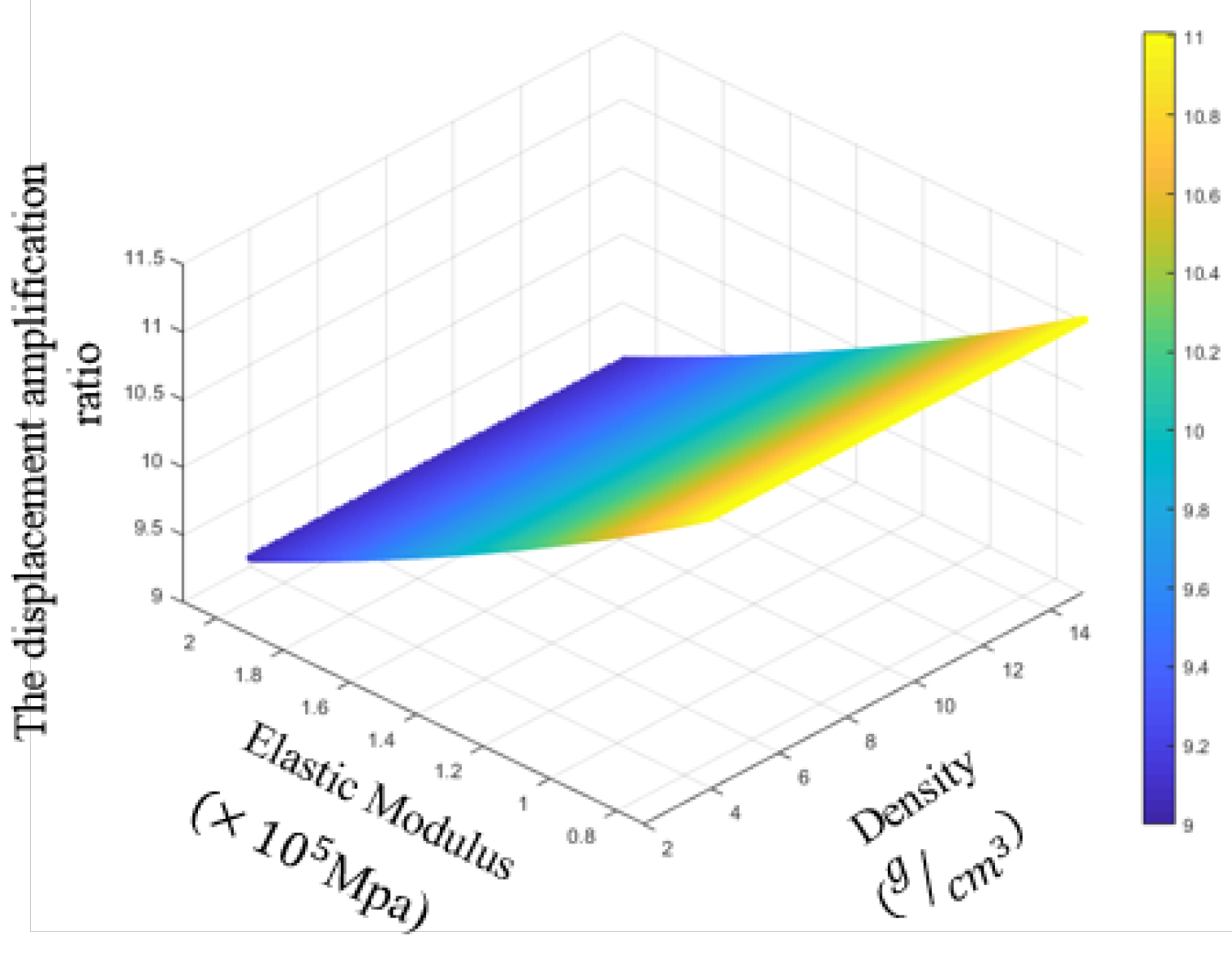
As the material basis and the carrier of the mechanism design, the materials represent an important aspect of the scientific and technological research into these mechanisms. As a result, it is also necessary to study the effects of the material properties on the magnification ratio (see
Figure 10). The figure shows that the displacement amplification ratio decreases with increasing material elastic modulus and that the ratio is independent of the material density.
4. Dynamic Characteristics Analysis
During the dynamic analysis, the frequency . The piezoelectric actuator is set to apply an excitation force to the compliant mechanism, where . The solution to this equation must therefore be obtained.
4.1. Resonance Frequency
Substitution of the parameters for the rhombus-type compliant mechanism allows the resonance frequency results for the mechanism to be calculated here. Using the thickness, width, and angle of the model bridge arm as the variables, the effects of the main geometric parameters on the dynamic characteristics of the rhombus-type compliant mechanism are discussed here. (Note that the bridge-type compliant mechanism is a special rhombus-type compliant mechanism and will not be discussed here.)
(1) Flexible unit
Figure 11(a) shows that the first-order resonance frequency of the mechanism increases as the bridge arm thickness increases, and the error between the MSTMM and FEM results also increases accordingly.
Figure 11(b) shows that the first-order resonance frequency decreases as the arm angle of the mechanism increases. Unlike the static properties, there is no longer a peak point that varies with the angle. A smaller angle corresponds to a larger error in this case. The MSTMM curve in
Figure 11(c) shows that the first-order resonance frequency of the mechanism is not affected by the arm width, although the FEM curve drops slightly. The reason for this phenomenon is that this model is only designed for the dimensions on a plane.
(2) Pseudo-rigid body element
Figure 12 shows the effects of the pseudo-rigid body unit parameters on the resonant frequency of the mechanism. The resonance frequency of the mechanism is shown to decrease as the length of the input rigid body unit and the height of the output rigid body increase, but the frequency increases as the length of the output rigid body unit increases.
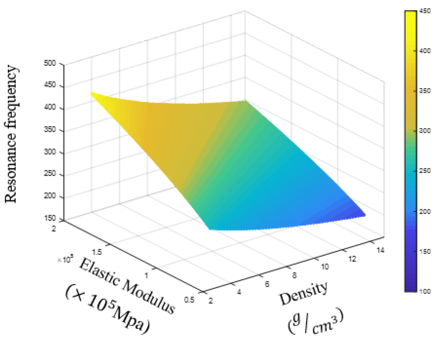
(3) Material properties
Figure 13 shows that as the elastic modulus increases, the density decreases, and the main resonance frequency increases.
4.2. Frequency response analysis
Substitution of the geometric parameters allows the frequency response of the mechanism in all directions to be calculated here.
Figure 14 shows the frequency response results for the rhombus-type compliant mechanism in the main direction in the plane.
Figure 14(a), (b), and (c) show the FEM simulation results, and (d), (e), and (f) show the MSTMM calculation results. Comparison of the figures shows highly similar results, which again verifies the accuracy of the proposed method.
5. Hybrid compliance improvement model
Based on analysis of the previous results, it is feasible to use the MSTMM to describe both the dynamic and static characteristics of the compliant mechanism. However, there is a certain error between the established mathematical model and the finite element model, and at small angles in particular, the gap between these models is especially obvious. This error increases when the thickness of the bridge arm increases and when the angle of the bridge arm decreases.
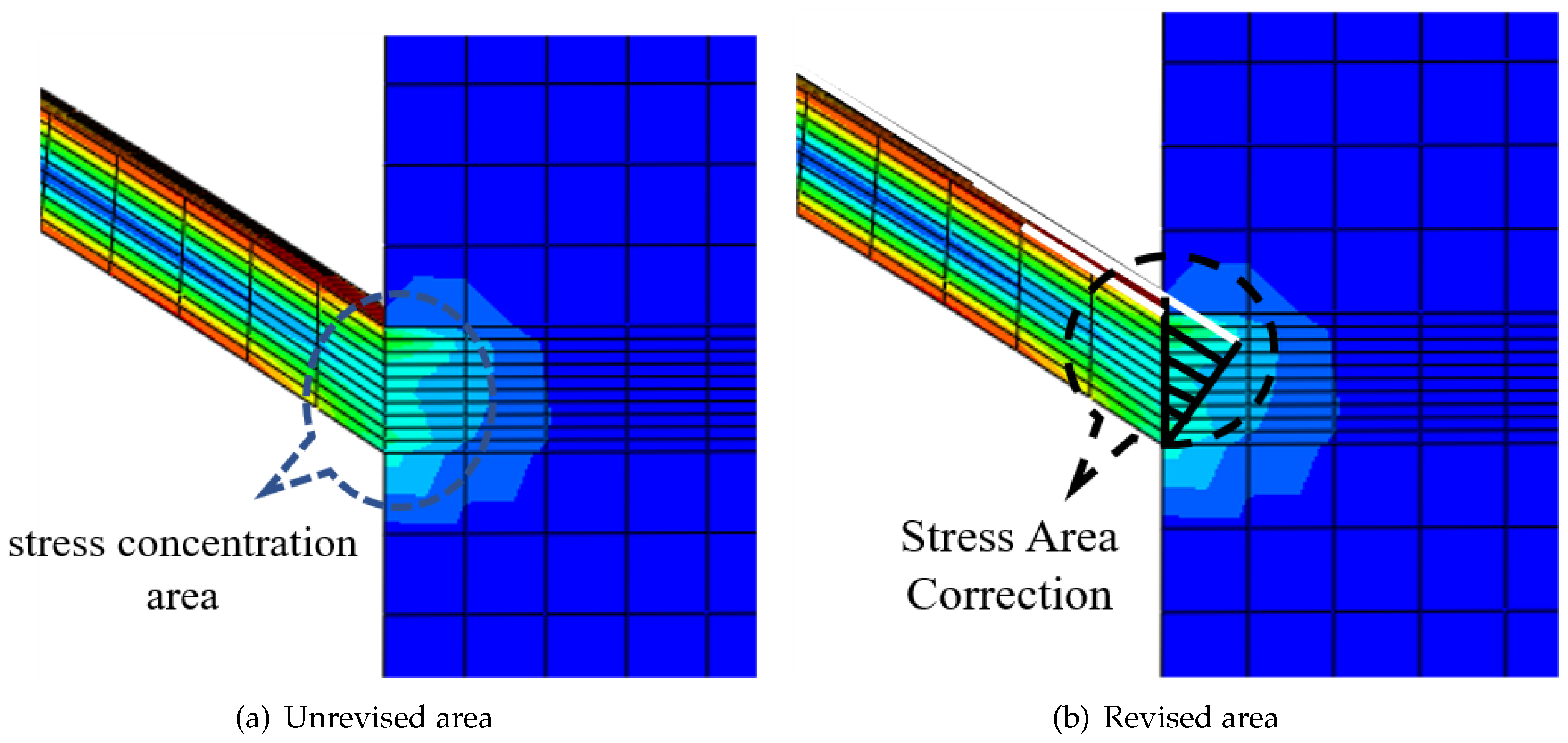
Through a combination of analysis and comparison, it was found that the main cause of this phenomenon is the stress concentration effect in the connection area between the bridge arm of the compliant amplifying mechanism and the rigid body unit (see
Figure 15(a)), which results in uneven distribution of the deformation[
19,
38].In addition, this error also occurs because the FEM results that are used as reference values will be affected by the quality and size of the mesh.
The deformation area (see
Figure 15(b)) is roughly triangular in shape, which is complementary to the beam shape. To describe the resonance frequency characteristics of the amplifying mechanism accurately by weakening the stress concentration effects, we constructed a hybrid flexibility-modified model of the amplifying mechanism. Specific measures were applied to establish a stress concentration transfer matrix in this area and then add it to the total transfer equation to correct the equation results. A triangular deformation area was added into the beam deformation area. Therefore, the stress concentration transfer matrix and the beam transfer matrix can be combined to give a new modified beam transfer matrix. The length of the modified beam is:
where,
. And
,
represent correction coefficients, which is used to perform numerical fitting according to the different connection angles, thicknesses, and connection width of the pseudo-rigid body element of the bridge arm, etc[
39,
40,
41].
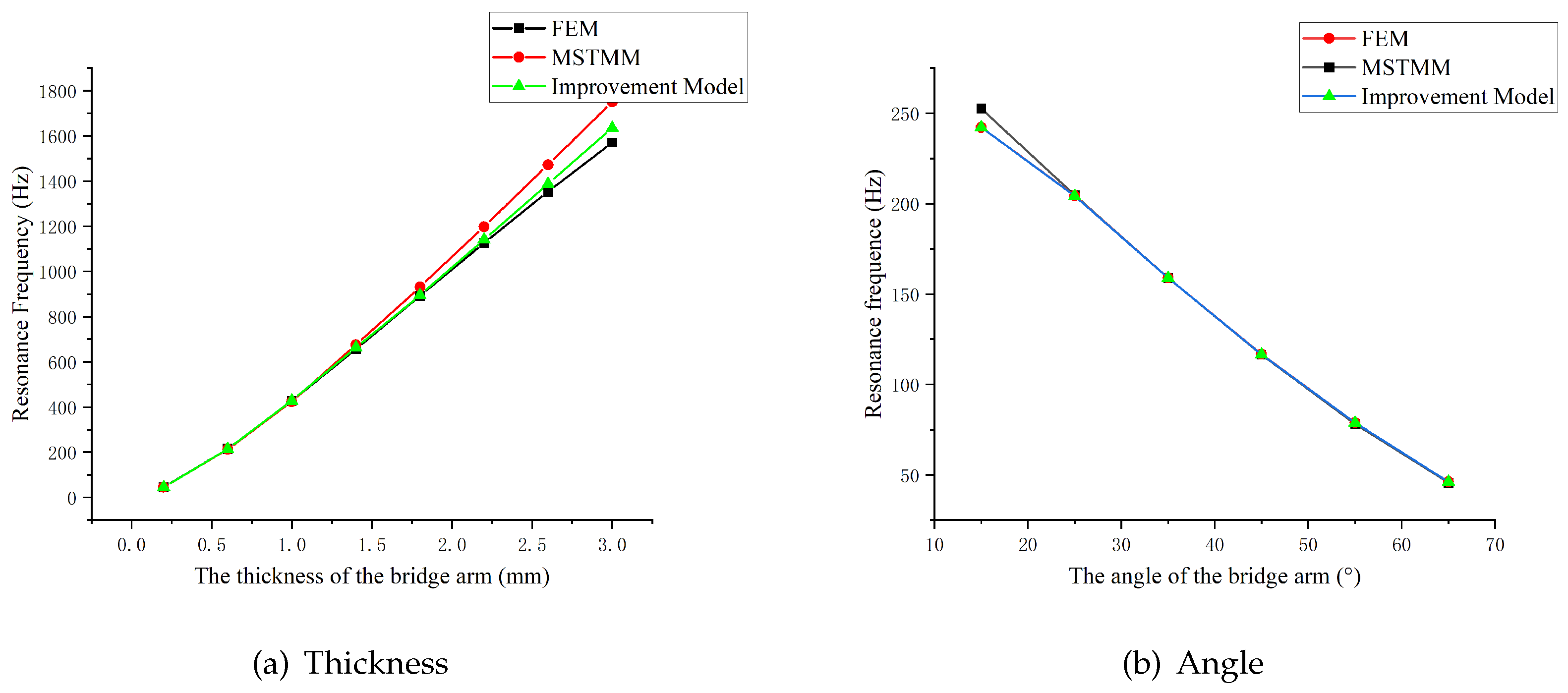
Comparison results for the natural frequencies of the improved model and those of the model before improvement are shown in
Figure 16.
Figure 16(a) shows the corrected curves for the amplifying mechanism for different bridge arm thicknesses under the condition that the correction coefficient K remains constant.
Figure 16(b) illustrates the improvement made by the correction coefficient when applied to the dynamic results of the mechanism at different arm angles. The results show that the modified model can describe the dynamic performance of the mechanism more accurately than the mathematical models before the modification.
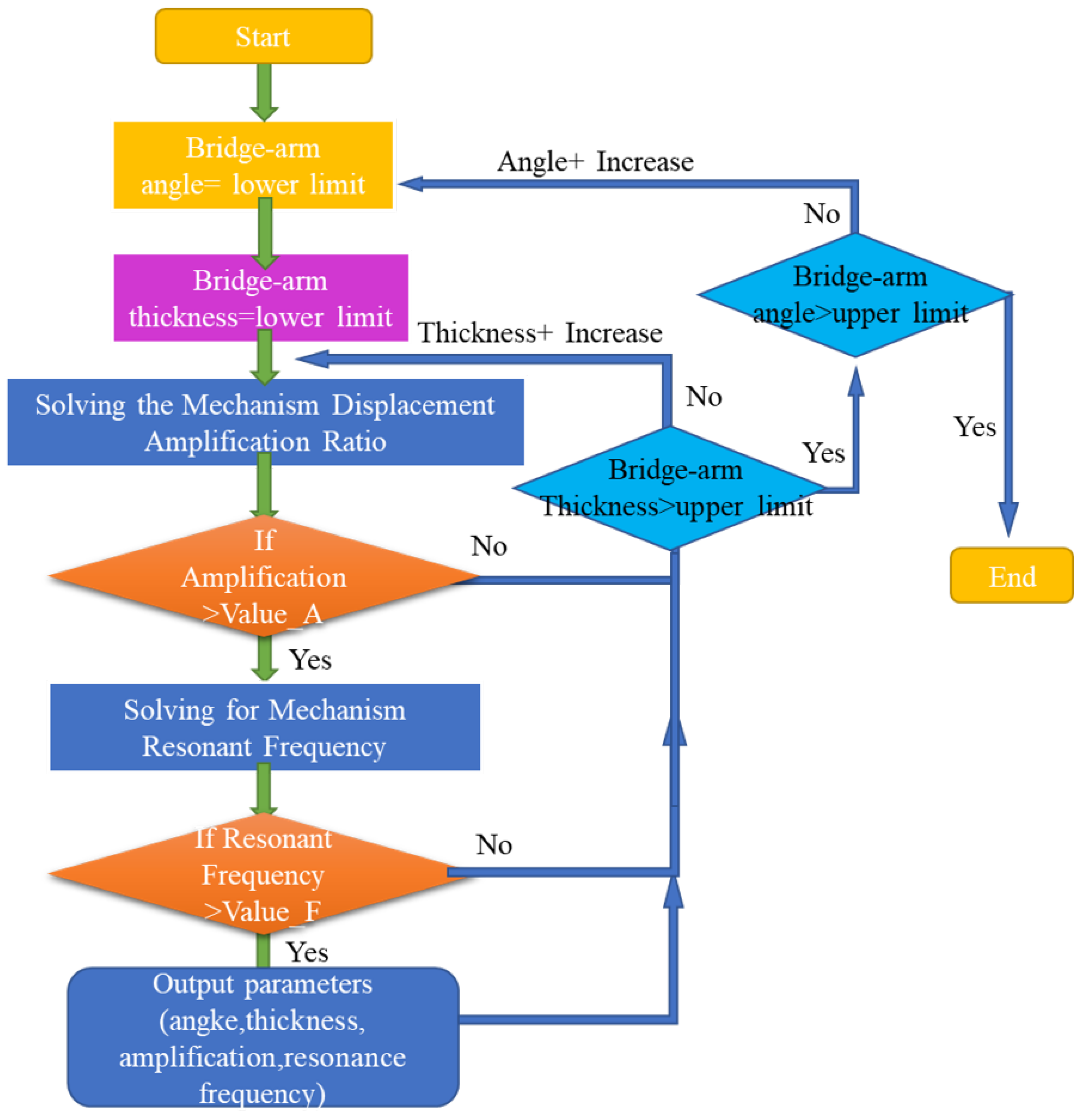
6. Iterative Optimization
From the results of the characteristic analyses described in the previous sections, we have gained a clear understanding of the main parameters that affect the amplification ratio and the resonance frequency of the amplifying mechanism. These two characteristics are contradictory when used in selection of the bridge arm thickness, as can be seen from
Figure 7 and
Figure 13(a). Therefore, it is impossible to design a mechanism that has the two best values for these characteristics simultaneously, and the thickness and angle of the bridge arm can only be selected according to specific design requirements[
42].
Using the MSTMM, we can establish a functional relationship between the dynamic and static characteristics and the main influencing parameters as follows:
On this basis, by performing iterative parameter optimization, the parameter values that meet the design requirements can be found and the optimization model is then designed[
32]. The optimization flowchart is shown in
Figure 17 (note that only selected angle and thickness parameters are given here).
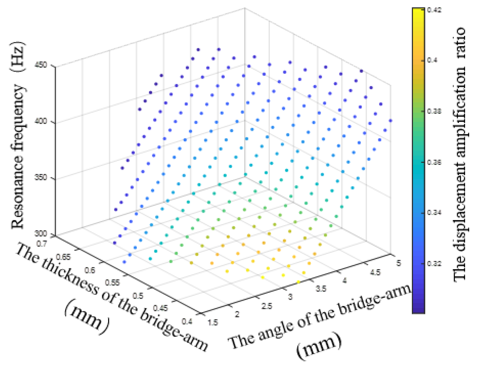
An output displacement of more than 300 µm and a main resonance frequency of more than 300 Hz were selected as the design goals (the piezoelectric actuator used is the PI product P-888.91). While considering of the effects of the calculation errors and the stress concentration, the structural parameter values with the best characteristic result values should be selected as far as possible during this process. Here, 80% of the troke is taken as the result value.
Figure 18 shows the values of all main parameters that meet the design requirements.
One set of results was processed up to the design stage. The specific parameters are listed in
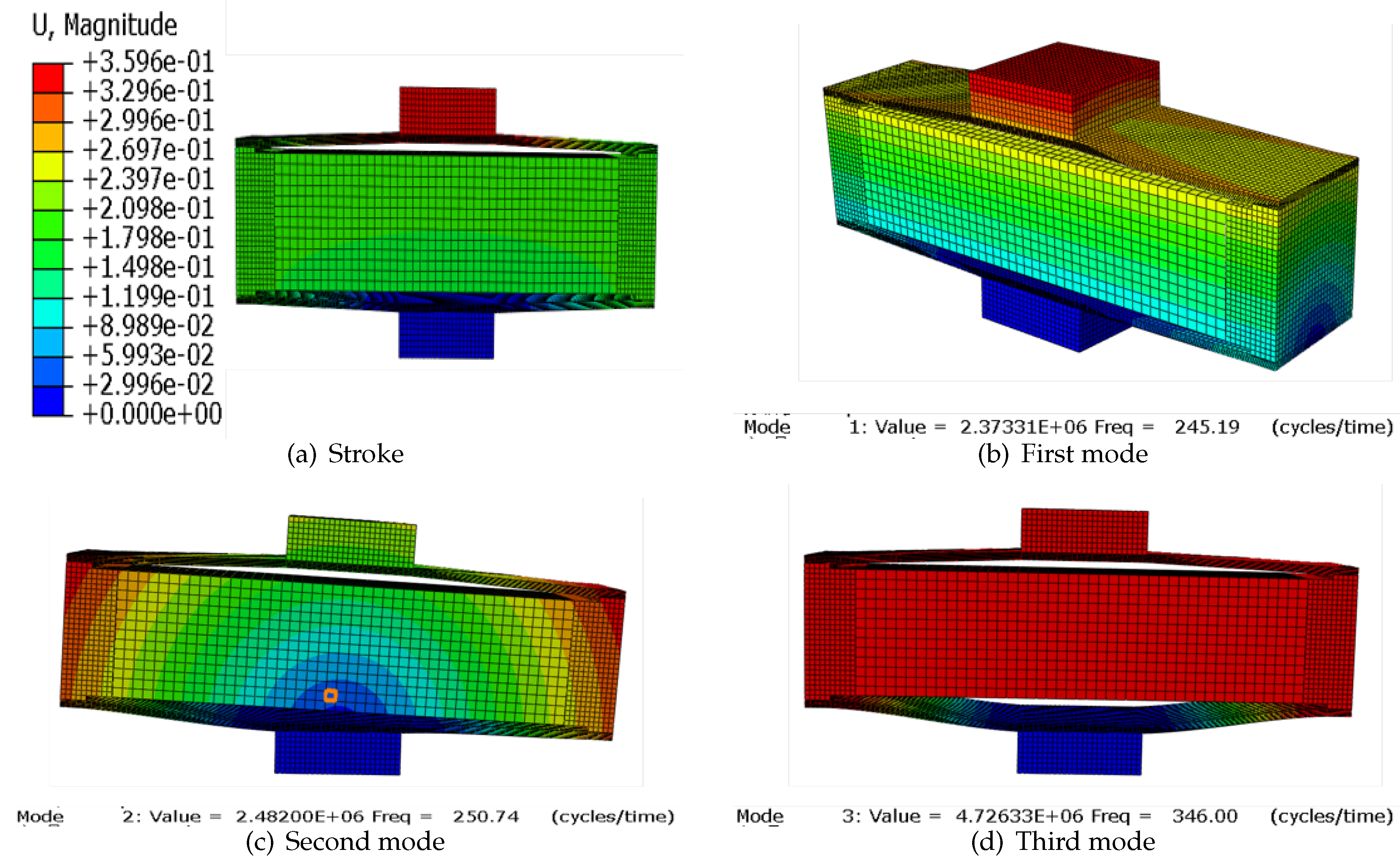
Table 1. The subsequent simulation results are shown in
Figure 19.
7. Experiment
To verify the feasibility of the proposed model, both rhombus-type and bridge-type compliant mechanism models were processed by wire cutting. The mechanisms were driven by piezoelectric ceramic actuators produced by PI, and the specific actuator parameters are given in
Table 2. The output displacement of the mechanism was measured using a laser displacement meter (CL-P070) with a resolution of 0.25 µm.
The experimental setup is pictured in
Figure 20. By inputting a voltage to the piezoelectric stack, the mechanism produces an output displacement and thus allows the static characteristics and the dynamic characteristics of the rhombus-type amplifying mechanism to be obtained [
43].
First, the curve that shows the relationship between the output displacement and the input voltage of the amplifying mechanism is measured, as shown in
Figure 21. Second, the maximum output displacement of the mechanism is tested (see the results in Table 6-2). Third,
Figure 22 shows the frequency sweeping results obtained for the mechanism. These results show that the resonance frequency of the mechanism in the main direction is 334.8 Hz. From the experimental results, it was found that the output displacement error of the amplifying mechanism is approximately 7% and the main resonance frequency error is approximately 3%.
Table 3.
Maximum output displacement test results for the mechanism
Table 3.
Maximum output displacement test results for the mechanism
| Times |
1 |
2 |
3 |
Avg |
| Stroke(m) |
336.75 |
336 |
337.75 |
336.5 |
Strong similarity was observed between the results of the finite element analysis and those of the proposed model, and any deviations appeared to be caused by manufacturing and assembly errors of the amplifying mechanism, the installation of the piezo-stacks, and sensor errors when affected by measurement noise, light interference, vibration, and other factors[
10,
20].
8. Application
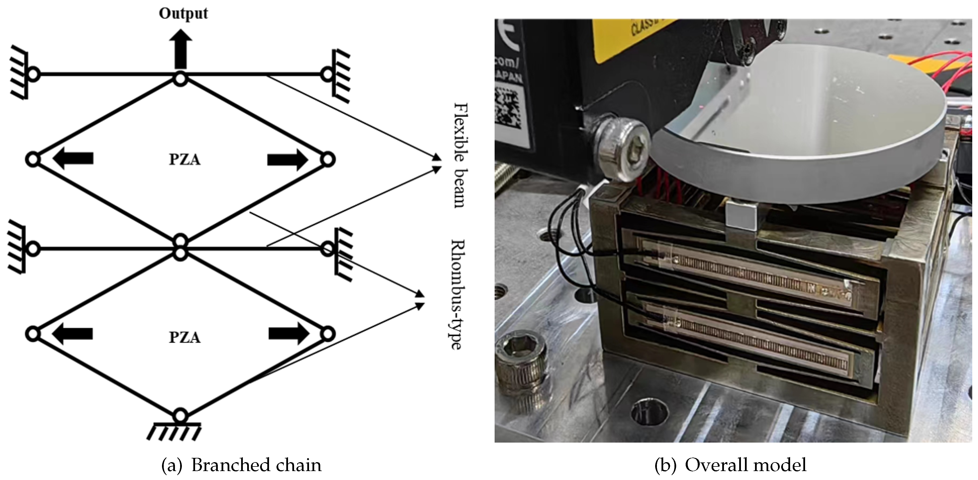
The rhombus-type mechanism analyzed in this article can be utilized for applications where large strokes and high natural frequencies are required. An example of a possible application can be found in focusing mechanisms. The rhombus-type amplifying mechanism mainly amplifies the displacement of the actuators, and a thin and long flexible beam is attached to it to limit the offset of the amplifying mechanism in the non-working direction(see
Figure 23(a)), so as to realize the translation of the focusing mechanism in the one-dimensional direction[
44,
45,
46,
47].
Based on the analysis method proposed above, the mathematical model of the one-dimensional focusing mechanism is established. Next, with the goal of large stroke and high natural frequency, the main design dimensions of the focusing mechanism are optimized using the iterative optimization method proposed in
Section 6. The specific performance parameters of the focusing mechanism are listed in
Table 4.
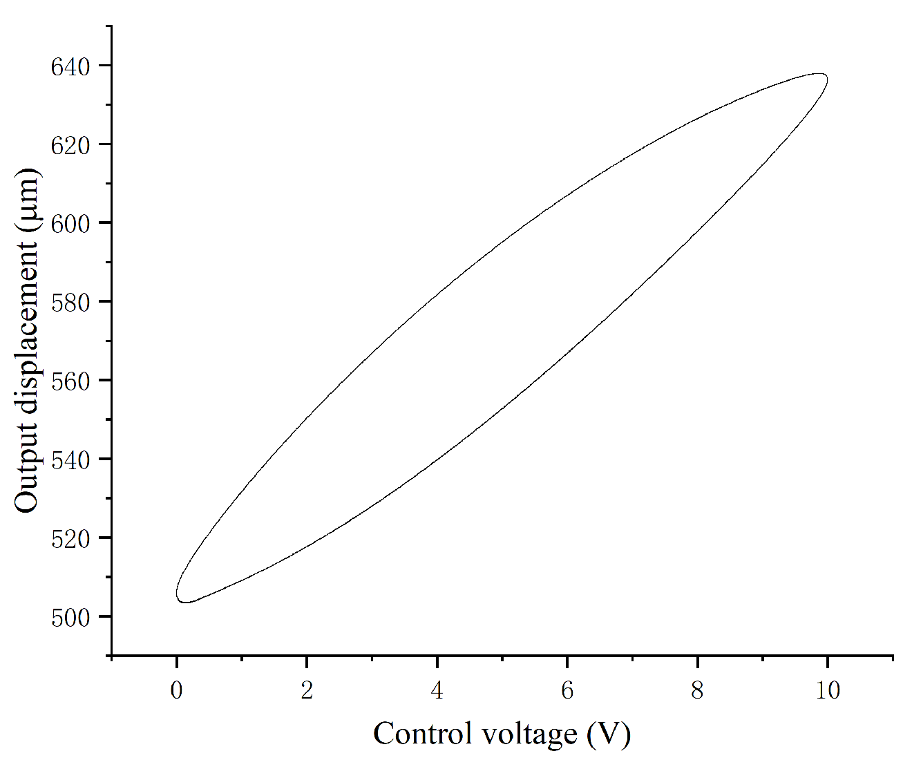
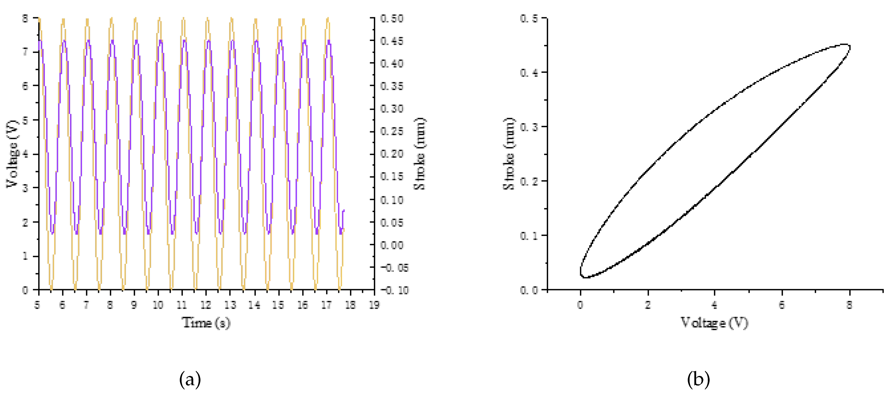
The model is processed by wire cutting technology. And the material selection is the same as above (Spring steel 65Mn). A simple test was carried out on the model to verify the feasibility of using the rhombus-type mechanism in the focusing mechanism. The output displacement is measured with a laser displacement meter, and when the PZA is at 120V, a displacement of about 430um is produced. And the frequency response[
48] is measured with the frequency response meter, and the resonance peak is near 302Hz(see
Figure 24 and
Figure 25).
In this case, the feasibility of determining the optimal values for the mechanism’s parameters based on the MSTMM approach is verified, and certain reference values are provided for design of the precision focusing mechanism.
9. Discussion and Conclusions
In this paper, a parameterized dynamic and static mathematical model of a compliant amplifying mechanism has been established based on the multi-body system transfer matrix method. On this basis, the effects of the main parameters of the mechanism on the static characteristics of the displacement amplification ratio and the dynamic characteristics of the resonance frequency in the model were analyzed using the control variable method. The transfer matrix was corrected by adding correction coefficients that reduced the influence of stress concentration. Finally, the parameter values were largely optimized to meet the mechanism’s design requirements. Based on the discussion above, the main contributions of this paper can be summarized as follows:
1. A unified dynamic and static mathematical model of the compliant amplifying mechanism is established.
2. A comprehensive analysis of the effects of all geometric parameters and material properties on the dynamic and static characteristics of the mechanism has been performed.
3. The amplification ratio decreases with increasing bridge arm angle following a peak value, and decreases with decreasing arm thickness and length. Greater bridge arm thickness leads to a smaller arm angle, a longer output rigid body, and a higher first-order resonance frequency. Larger values for the length and height of the mechanism’s input rigid body and a larger value for the height of the output rigid body cause the first-order resonance frequency to decrease.
4. An optimal rhombus-type amplifying mechanism model and a spatial focusing mechanism were designed using the iterative optimization method, which has a certain reference value for use in engineering applications.
5. The model was processed via wire cutting and the experiments were then performed. The experimental results showed that the displacement amplification ratio error and the first-order main resonance frequency error are approximately 7% and 3%, respectively.
It was thus proved that it is feasible to use the mathematical model of the compliant amplification mechanism based on the MSTMM to describe the mechanism’s dynamic and static characteristics using the analysis above.
Author Contributions
Conceptualization, J.W., Z.J., Z.X., Z.N. and B.Q.; methodology, J.W., Z.J.; software, J.W., Z.J.; validation, J.W. and Z.J.; formal analysis, J.W.; writing—original draft preparation, J.W., Z.J.; writing—review and editing, J.W., Z.J., Z.X., Z.N. and B.Q. All authors have read and agreed to the published version of the manuscript.
Funding
This research was funded by the Young Scientists Fund of the National Natural Science Foundation of China [grant number 12003039] and the Young Scientists Fund of the National Natural Science Foundation of China [grant number 2022-JCJQ-JJ-031].
Institutional Review Board Statement
Not applicable.
Informed Consent Statement
Not applicable
Data Availability Statement
Not applicable.
Acknowledgments
This research was funded by the Young Scientists Fund of the National Natural Science Foundation of China [grant number 12003039] and the Young Scientists Fund of the National Natural Science Foundation of China [grant number 2022-JCJQ-JJ-031].
Conflicts of Interest
The authors declare no conflict of interest.
References
- Ling, M.; Wang, J.; Wu, M.; Cao, L.; Fu, B. Design and modeling of an improved bridge-type compliant mechanism with its application for hydraulic piezo-valves. Sensors and Actuators A: Physical 2021, 324, 112687. [Google Scholar] [CrossRef]
- Zhang, Q.; Zhao, J.; Peng, Y.; Pu, H.; Yang, Y. A novel amplification ratio model of a decoupled XY precision positioning stage combined with elastic beam theory and Castigliano’s second theorem considering the exact loading force. Mechanical Systems and Signal Processing 2020, 136, 106473. [Google Scholar] [CrossRef]
- Shen, X.; Zhang, L.; Qiu, D. A lever-bridge combined compliant mechanism for translation amplification. Precision Engineering 2021, 67, 383–392. [Google Scholar] [CrossRef]
- Ling, M.; Zhang, X. Coupled dynamic modeling of piezo-actuated compliant mechanisms subjected to external loads. Mechanism and Machine Theory 2021, 160, 104283. [Google Scholar] [CrossRef]
- Li, Y.; Bi, S.; Zhao, C. Analytical modeling and analysis of rhombus-type amplifier based on beam flexures. Mechanism and Machine Theory 2019, 139, 195–211. [Google Scholar] [CrossRef]
- Zhang, L.; Liu, P.; Yan, P. A novel compact tilt stage with additive manufacturable spatial flexure mechanism driven by asymmetric stiffness. Mechanism and Machine Theory 2021, 166, 104443. [Google Scholar] [CrossRef]
- Dong, W.; Zhang, Q.; Zhu, D.; Chen, T.; Gao, Y. Design and analysis of a piezo-actuated 2-DOF high-precision parallel pointing mechanism capable of carrying a heavy load. Precision Engineering 2023, 81, 50–59. [Google Scholar] [CrossRef]
- Elsisy, M.M.; Arafa, M.H.; Saleh, C.A.; Anis, Y.H. Modeling of a Symmetric Five-Bar Displacement Amplification Compliant Mechanism for Energy Harvesting. Sensors 2021, 21, 1095. [Google Scholar] [CrossRef]
- Wu, H.; Lai, L.; Zhu, L. Analytical model and experimental verification of an elliptical bridge-type compliant displacement amplification mechanism. Review of Scientific Instruments 2021, 92, 055109. [Google Scholar] [CrossRef]
- Cao, J.; Ling, M.; Inman, D.J.; Lin, J. Generalized constitutive equations for piezo-actuated compliant mechanism. Smart Materials and Structures 2016, 25, 095005. [Google Scholar] [CrossRef]
- Dong, W.; Chen, F.; Gao, F.; Yang, M.; Sun, L.; Du, Z.; Tang, J.; Zhang, D. Development and analysis of a bridge-lever-type displacement amplifier based on hybrid flexure hinges. Precision Engineering 2018, 54, 171–181. [Google Scholar] [CrossRef]
- Chen, F.; Li, H.; He, W.; Li, W.; Dong, W. Analysis and comparison of the displacement amplifiers with a generalized mathematical model. 2019 IEEE 9th Annual International Conference on CYBER Technology in Automation, Control, and Intelligent Systems (CYBER). IEEE, 2019, pp. 1386–1391.
- Song, D.; Zhu, B.; Li, H.; Zhang, X. Kinetostatic Modeling of Piezoelectric Displacement Amplifiers Based on Matrix Displacement Method. Intelligent Robotics and Applications: 14th International Conference, ICIRA 2021, Yantai, China, October 22–25, 2021, Proceedings, Part II 14. Springer, 2021, pp. 404–414.
- Chen, F.; Zhang, Q.; Dong, W.; Sun, L. Design and test of a compact large-stroke dual-drive linear-motion system. Mechanical Systems and Signal Processing 2022, 180, 109438. [Google Scholar] [CrossRef]
- Zhou, S.; Yan, P. Design and Analysis of a Hybrid Displacement Amplifier Supporting a High-Performance Piezo Jet Dispenser. Micromachines 2023, 14, 322. [Google Scholar] [CrossRef] [PubMed]
- Cao, L. A New Static And Dynamic Model For Bridge-Type Displacement Amplifier For Use In Piezoelectric Actuators. 2020 15th Symposium on Piezoelectrcity, Acoustic Waves and Device Applications (SPAWDA). IEEE, 2021, pp. 460–464.
- Ling, M.; Cao, J.; Pehrson, N. Kinetostatic and dynamic analyses of planar compliant mechanisms via a two-port dynamic stiffness model. Precision Engineering 2019, 57, 149–161. [Google Scholar] [CrossRef]
- Choi, K.B.; Lee, J.J.; Kim, G.H.; Lim, H.J.; Kwon, S.G. Amplification ratio analysis of a bridge-type mechanical amplification mechanism based on a fully compliant model. Mechanism and Machine Theory 2018, 121, 355–372. [Google Scholar] [CrossRef]
- Ling, M.; Cao, J.; Zeng, M.; Lin, J.; Inman, D.J. Enhanced mathematical modeling of the displacement amplification ratio for piezoelectric compliant mechanisms. Smart Materials and Structures 2016, 25, 075022. [Google Scholar] [CrossRef]
- Xu, Q.; Li, Y. Analytical modeling, optimization and testing of a compound bridge-type compliant displacement amplifier. Mechanism and machine theory 2011, 46, 183–200. [Google Scholar] [CrossRef]
- Liu, P.; Yan, P. A new model analysis approach for bridge-type amplifiers supporting nano-stage design. Mechanism and Machine Theory 2016, 99, 176–188. [Google Scholar] [CrossRef]
- Qi, K.q.; Xiang, Y.; Fang, C.; Zhang, Y.; Yu, C.s. Analysis of the displacement amplification ratio of bridge-type mechanism. Mechanism and Machine Theory 2015, 87, 45–56. [Google Scholar] [CrossRef]
- Chen, S.; Ling, M.; Zhang, X. Design and experiment of a millimeter-range and high-frequency compliant mechanism with two output ports. Mechanism and Machine Theory 2018, 126, 201–209. [Google Scholar] [CrossRef]
- Ye, G.; Li, W.; Wang, Y.q.; Yang, X.f.; Yu, L. Kinematics analysis of bridge-type micro-displacement mechanism based on flexure hinge. The 2010 IEEE International Conference on Information and Automation. IEEE, 2010, pp. 66–70.
- Chen, J.; Zhang, C.; Xu, M.; Zi, Y.; Zhang, X. Rhombic micro-displacement amplifier for piezoelectric actuator and its linear and hybrid model. Mechanical Systems and Signal Processing 2015, 50, 580–593. [Google Scholar] [CrossRef]
- Shen, C.L.; Dong, J.S.; Tian, F.J. The Analytical Modeling and Finite Element Analysis of a Bridge-type Displacement Amplifier. Applied Mechanics and Materials. Trans Tech Publ, 2013, Vol. 397, pp. 652–655.
- Das, T.K.; Shirinzadeh, B.; Al-Jodah, A.; Ghafarian, M.; Pinskier, J. A novel compliant piezoelectric actuated symmetric microgripper for the parasitic motion compensation. Mechanism and Machine Theory 2021, 155, 104069. [Google Scholar]
- Zhu, W.L.; Zhu, Z.; Guo, P.; Ju, B.F. A novel hybrid actuation mechanism based XY nanopositioning stage with totally decoupled kinematics. Mechanical Systems and Signal Processing 2018, 99, 747–759. [Google Scholar] [CrossRef]
- Lin, C.; Zheng, S.; Jiang, M. Dynamic Analysis and Experiment of 6-DOF Compliant Platform Based on Bridge-Type Amplifier. Micromachines 2020, 11, 1024. [Google Scholar] [CrossRef]
- Liu, Y.; Xu, Q. Mechanical design, analysis and testing of a large-range compliant microgripper. Mechanical Sciences 2016, 7, 119–126. [Google Scholar] [CrossRef]
- Li, P.; Zhu, H.; Lai, L. An Improved Dynamic Model and Matrix Displacement Model for Distributed-Compliance Bridge-Type Amplification Mechanism. Actuators 2022, 11, 368. [Google Scholar] [CrossRef]
- Ling, M.; Cao, J.; Jiang, Z.; Zeng, M.; Li, Q. Optimal design of a piezo-actuated 2-DOF millimeter-range monolithic flexure mechanism with a pseudo-static model. Mechanical Systems and Signal Processing 2019, 115, 120–131. [Google Scholar] [CrossRef]
- Rui, X.; Wang, G.; Zhang, J. Transfer matrix method for multibody systems: theory and applications; John Wiley & Sons, 2018. [Google Scholar]
- Feyzollahzadeh, M.; Bamdad, M. A modified transfer matrix method to reduce the calculation time: A case study on beam vibration. Applied Mathematics and Computation 2020, 378, 125238. [Google Scholar] [CrossRef]
- Hu, J.; Wen, T.; He, J. Dynamics of compliant mechanisms using transfer matrix method. International Journal of Precision Engineering and Manufacturing 2020, 21, 2173–2189. [Google Scholar] [CrossRef]
- Jiang, M.; Rui, X.; Zhu, W.; Yang, F.; Zhang, J. Modeling and control of magnetorheological 6-DOF stewart platform based on multibody systems transfer matrix method. Smart Materials and Structures 2020, 29, 035029. [Google Scholar] [CrossRef]
- Zhu, W.; Chen, G.; Bian, L.; Rui, X. Transfer matrix method for multibody systems for piezoelectric stack actuators. Smart materials and structures 2014, 23, 095043. [Google Scholar] [CrossRef]
- Jing, Z.; Xu, M.; Wu, T.; Tian, Z. Development of a tilt-positioning mechanism driven by flextensional piezoelectric actuators. Review of Scientific Instruments 2016, 87, 085006. [Google Scholar] [CrossRef] [PubMed]
- Pilkey, W.D.; Pilkey, D.F.; Bi, Z. Peterson’s stress concentration factors; John Wiley & Sons, 2020. [Google Scholar]
- Pandey, M.; Young, B. Stress concentration factors of cold-formed high strength steel tubular T-joints. Thin-Walled Structures 2021, 166, 107996. [Google Scholar] [CrossRef]
- Pandey, M.; Young, B. Structural performance of cold-formed high strength steel tubular X-Joints under brace axial compression. Engineering Structures 2020, 208, 109768. [Google Scholar] [CrossRef]
- Ling, M.; Zhang, C.; Chen, L. Optimized design of a compact multi-stage displacement amplification mechanism with enhanced efficiency. Precision Engineering 2022, 77, 77–89. [Google Scholar] [CrossRef]
- Sun, X.; Chen, W.; Chen, W.; Qi, S.; Li, W.; Hu, C.; Tao, J. Design and analysis of a large-range precision micromanipulator. Smart Materials and Structures 2019, 28, 115031. [Google Scholar] [CrossRef]
- Li, C.; Liang, K.; Zhong, W.; Fang, J.; Sun, L.; Zhu, Y. Electrochemical coupled analysis of a micro piezo-driven focusing mechanism. Micromachines 2020, 11, 216. [Google Scholar] [CrossRef]
- Zhu, W.; Bian, L.; An, Y.; Chen, G.; Rui, X. Modeling and control of a two-axis fast steering mirror with piezoelectric stack actuators for laser beam tracking. Smart Materials and Structures 2015, 24, 075014. [Google Scholar] [CrossRef]
- Jing, Z.; Xu, M.; Feng, B. Modeling and optimization of a novel two-axis mirror-scanning mechanism driven by piezoelectric actuators. Smart Materials and Structures 2014, 24, 025002. [Google Scholar] [CrossRef]
- Wang, G.; Wang, Y.; Zhou, H.; Bai, F.; Chen, G.; Ma, J. Comprehensive approach to modeling and identification of a two-axis piezoelectric fast steering mirror system based on multi-component analysis and synthesis. Mechanical Systems and Signal Processing 2019, 127, 50–67. [Google Scholar] [CrossRef]
- Zhang, Y.; Yan, P. A Large Range Constant Force Microgripper With a Three-Stage Compliant Amplification Mechanism. IEEE Access 2022, 10, 58225–58232. [Google Scholar] [CrossRef]
Figure 1.
Rhombus-type and bridge-type compliant mechanisms
Figure 1.
Rhombus-type and bridge-type compliant mechanisms
Figure 2.
Equivalent models showing unit divisions of compliant amplifying mechanisms.
Figure 2.
Equivalent models showing unit divisions of compliant amplifying mechanisms.
Figure 3.
Unit topology diagram of compliant amplifying mechanism
Figure 3.
Unit topology diagram of compliant amplifying mechanism
Figure 4.
Local coordinate system for each unit.
Figure 4.
Local coordinate system for each unit.
Figure 5.
Relationships between the output displacement of the mechanism and the piezoelectric input voltage for the FEM and MSTMM models.
Figure 5.
Relationships between the output displacement of the mechanism and the piezoelectric input voltage for the FEM and MSTMM models.
Figure 6.
Effects of bridge arm parameters on displacement amplification ratio (Rhombus-type mechanism).
Figure 6.
Effects of bridge arm parameters on displacement amplification ratio (Rhombus-type mechanism).
Figure 7.
Effects of bridge arm parameters on displacement amplification ratio (Bridge-type mechanism)
Figure 7.
Effects of bridge arm parameters on displacement amplification ratio (Bridge-type mechanism)
Figure 8.
Effects of size of the input and output pseudo-rigid body units of the amplifying mechanisms on their displacement amplification ratio.
Figure 8.
Effects of size of the input and output pseudo-rigid body units of the amplifying mechanisms on their displacement amplification ratio.
Figure 9.
Effects of size of the bridge rigid units of the amplifying mechanism on the displacement amplification ratio (Bridge-type mechanism).
Figure 9.
Effects of size of the bridge rigid units of the amplifying mechanism on the displacement amplification ratio (Bridge-type mechanism).
Figure 10.
Effects of elastic modulus and material density on the displacement amplification ratio.
Figure 10.
Effects of elastic modulus and material density on the displacement amplification ratio.
Figure 11.
Effects of the main parameters of the amplifying mechanism on the first-order resonance frequency .
Figure 11.
Effects of the main parameters of the amplifying mechanism on the first-order resonance frequency .
Figure 12.
Effects of the main geometric parameters of the pseudo-rigid units on the resonant frequency.
Figure 12.
Effects of the main geometric parameters of the pseudo-rigid units on the resonant frequency.
Figure 13.
Effects of the elastic modulus and material density on the main resonant frequency.
Figure 13.
Effects of the elastic modulus and material density on the main resonant frequency.
Figure 14.
Mechanism frequency response curves from FEM and MSTMM models.
Figure 14.
Mechanism frequency response curves from FEM and MSTMM models.
Figure 15.
Stress concentration area and stress correction area.
Figure 15.
Stress concentration area and stress correction area.
Figure 16.
Corrected model curves
Figure 16.
Corrected model curves
Figure 17.
Iterative optimization process flowchart.
Figure 17.
Iterative optimization process flowchart.
Figure 18.
Iterative optimization results.
Figure 18.
Iterative optimization results.
Figure 19.
Finite element results for the design model.
Figure 19.
Finite element results for the design model.
Figure 20.
(a) Experimental setup and (b) Schematic diagram of the overall operation experimental system
Figure 20.
(a) Experimental setup and (b) Schematic diagram of the overall operation experimental system
Figure 21.
Output displacement versus input voltage relationship for the mechanism.
Figure 21.
Output displacement versus input voltage relationship for the mechanism.
Figure 22.
Frequency sweeping result for the amplifying mechanism.
Figure 22.
Frequency sweeping result for the amplifying mechanism.
Figure 23.
Precision focusing mechanism.
Figure 23.
Precision focusing mechanism.
Figure 24.
(a) Input and output curves, and (b) output hysteresis curve for the focusing mechanism.
Figure 24.
(a) Input and output curves, and (b) output hysteresis curve for the focusing mechanism.
Figure 25.
Frequency sweeping result for the focusing mechanism.
Figure 25.
Frequency sweeping result for the focusing mechanism.
Table 1.
Main parameters of the amplifying mechanism
Table 1.
Main parameters of the amplifying mechanism
|
c(mm) |
|
b(mm) |
|
|
| - |
10 |
2.6 |
0.6 |
10 |
4 |
|
|
|
E(Mpa) |
|
|
| 2 |
12 |
Al7075 |
71000 |
0.33 |
|
Table 2.
Main parameters of the piezoelectric actuator
Table 2.
Main parameters of the piezoelectric actuator
| Dimensions(mm×mm×mm) |
Maximum travel range(um) |
|
|
E(MPa) |
| 10×10×36 |
|
7.5 |
0.3 |
36000 |
Table 4.
Specific performance parameters of the focusing mechanism
Table 4.
Specific performance parameters of the focusing mechanism
| Performance |
Value |
Unit |
| Stroke |
420 |
um |
| Resonance frequency |
300 |
Hz |
| Height |
44 |
mm |
| Length |
54 |
mm |
| Width |
54 |
mm |
| Mass |
195 |
g |
|
Disclaimer/Publisher’s Note: The statements, opinions and data contained in all publications are solely those of the individual author(s) and contributor(s) and not of MDPI and/or the editor(s). MDPI and/or the editor(s) disclaim responsibility for any injury to people or property resulting from any ideas, methods, instructions or products referred to in the content. |
© 2023 by the authors. Licensee MDPI, Basel, Switzerland. This article is an open access article distributed under the terms and conditions of the Creative Commons Attribution (CC BY) license (http://creativecommons.org/licenses/by/4.0/).
