1. Introduction
Laser beam welding of butt-jointed sheets is a challenging task due to pre-process-related deviations of the wrought material (e.g., production tolerances) and process-induced deviations during the welding process (e.g., thermal distortion). The resulting gap between the parts to be joined is of fundamental importance as it has a significant influence on process stability and seam quality [
1]. By affecting the energy absorption within the keyhole and the conditions of melt and vapor flow, the joint gap has a major impact on the pressure balance of the keyhole, which is crucial for keyhole stability [
2]. As a result, the formation of weld imperfections (e.g., spatter, pores) can differ depending on the gap size. It can therefore be concluded that the detection of the gap during the welding process is of fundamental importance in terms of quality assurance and environmental efficiency.
State-of-the-art methods for classifying and detecting joint gaps typically involve optical and tactile measuring techniques (e.g., [
3,
4]). However, these methods often require expensive modifications to clamping and system technology, as well as direct access to the measurement site. In contrast, acoustic process monitoring has proven to be highly advantageous due to its ability to integrate sensors into fixtures (airborne and structure-borne acoustic emission sensors) and position them in versatile external locations, allowing for adaptable sensor placement. This approach offers the added benefit of detecting hidden seam defects. Previous studies have successfully utilized acoustic analysis of process emissions to predict spatter-induced loss of mass [
5], monitor penetration depth [
6,
7], differentiate between heat conduction and deep penetration welding processes [
8,
9], and establish connections between disparate sensor systems using feature-based machine learning [
10]. Despite these advancements, the implementation of an acoustic process monitoring system specifically designed to detect and quantify joint gaps in laser beam welding has not yet been achieved.
Acoustic-based fault detection in welding poses several challenges. Firstly, there is a significant cost associated with collecting a substantial amount of industrial data, which must then be annotated by experts. Secondly, the diversity of data presents a challenge, as it is impractical to simulate all potential faults in the welding process. The third challenge revolves around selecting and placing appropriate sensors for process measurement, considering their sensitivity to background noise. Additionally, AI-based automated quality monitoring systems face significant challenges in industrial settings due to factors such as a large volume of data, data imbalance, and the need for expert annotations.
Several countermeasures have been proposed in recent years to address the challenges discussed above. Data scarcity can be overcome using data augmentation methods, such as random rotations, spec augment, mixup, or adding noise to the actual training data, which create synthetic data points through transformations [
11,
12]. These techniques help tackle the diversity challenge by introducing more varied instances. Further, data imbalance can be addressed using the synthetic minority over-sampling technique (SMOTE) method [
13], which generates synthetic examples for the minority class. These countermeasures enhance model effectiveness and fairness.
Acoustic-based fault detection methods typically involve the analysis of various attributes of sound signals, including temporal patterns, frequency components, and signal intensity. However, these methods can be affected by factors such as variations in background noise, sensor positioning, and minor process deviations, which can impact the distinctive characteristics of the sound signals. To address these challenges, contemporary data processing techniques and robust training approaches for deep learning models can be employed to facilitate the detection and extraction of process relevant signal components spanning the entire audible to ultrasonic frequency range [
14,
15].
Recent studies in industrial sound analysis have yielded promising results by employing Convolutional Neural Network (CNN)-based methods for audio event detection and classification [
16,
17,
18,
19]. These techniques have proven successful when applied to time-frequency representations, specifically spectrograms, as CNNs possess the capacity to capture local patterns and spatial dependencies within audio signals. Furthermore, the neural networks' capability to learn complex patterns, ability to perform end-to-end learning, and their scalability and adaptability have motivated their selection over traditional machine learning algorithms [
18]. Additionally, industrial audio signals, such as those from welding processes, often contain substantial background noise, necessitating laborious manual feature engineering to extract relevant signal characteristics [
19]. However, CNNs can automatically learn meaningful audio features, including frequency patterns and spectral characteristics, without the need for additional manual feature engineering [
17]. This work aims to use the CNN architecture for the automated detection of gap formation in laser beam butt welding.
2. Materials and Methods
2.1. Specimen Configuration
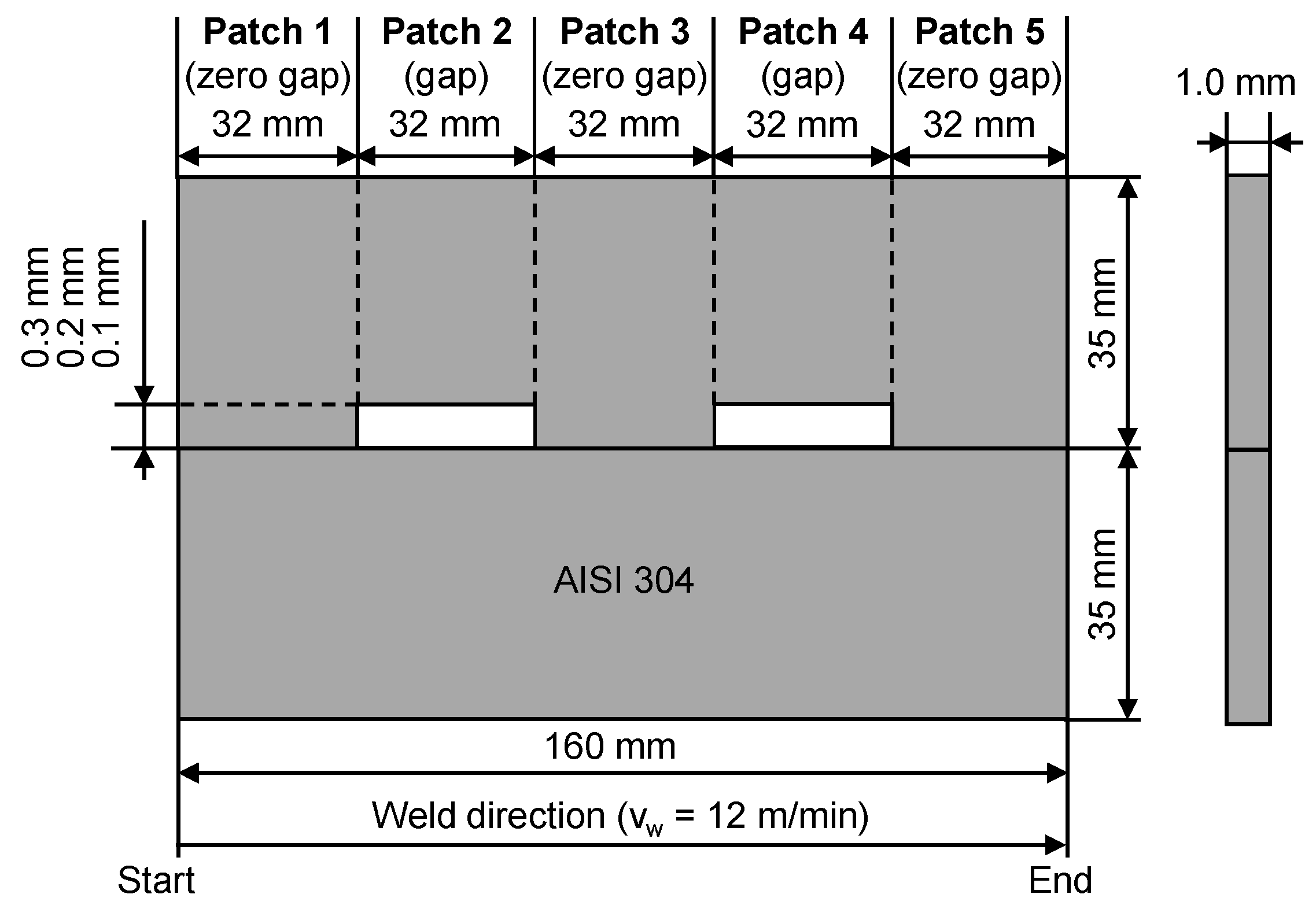
AISI 304 (X5CrNi18-10, 1.4301) high-alloy austenitic steel with a sheet thickness of 1 mm was used for the experiments (cf.
Figure 1). To investigate the influence of the joint gap, defined gaps were introduced by machining notches (0.1 – 0.3 mm) into one of the two sheets at two different positions. This resulted in a total of 5 different patch sections (3 x zero gap, 2 x joint gap) for each butt joint configuration. The direction of rolling of the sheets was the same as the welding direction.
2.2. Weld Setup
A disk laser (TruDisk 5000.75, Trumpf Laser- und Systemtechnik GmbH, Ditzingen, Germany) with a maximum power of
Pmax = 5 kW and a wavelength of
λ = 1030 nm was coupled to a stationary arranged welding optics (BEO D70, Trumpf Laser- und Systemtechnik GmbH, Ditzingen, Germany) providing a focal diameter of
dspot = 600 µm for laser beam butt welding (cf.
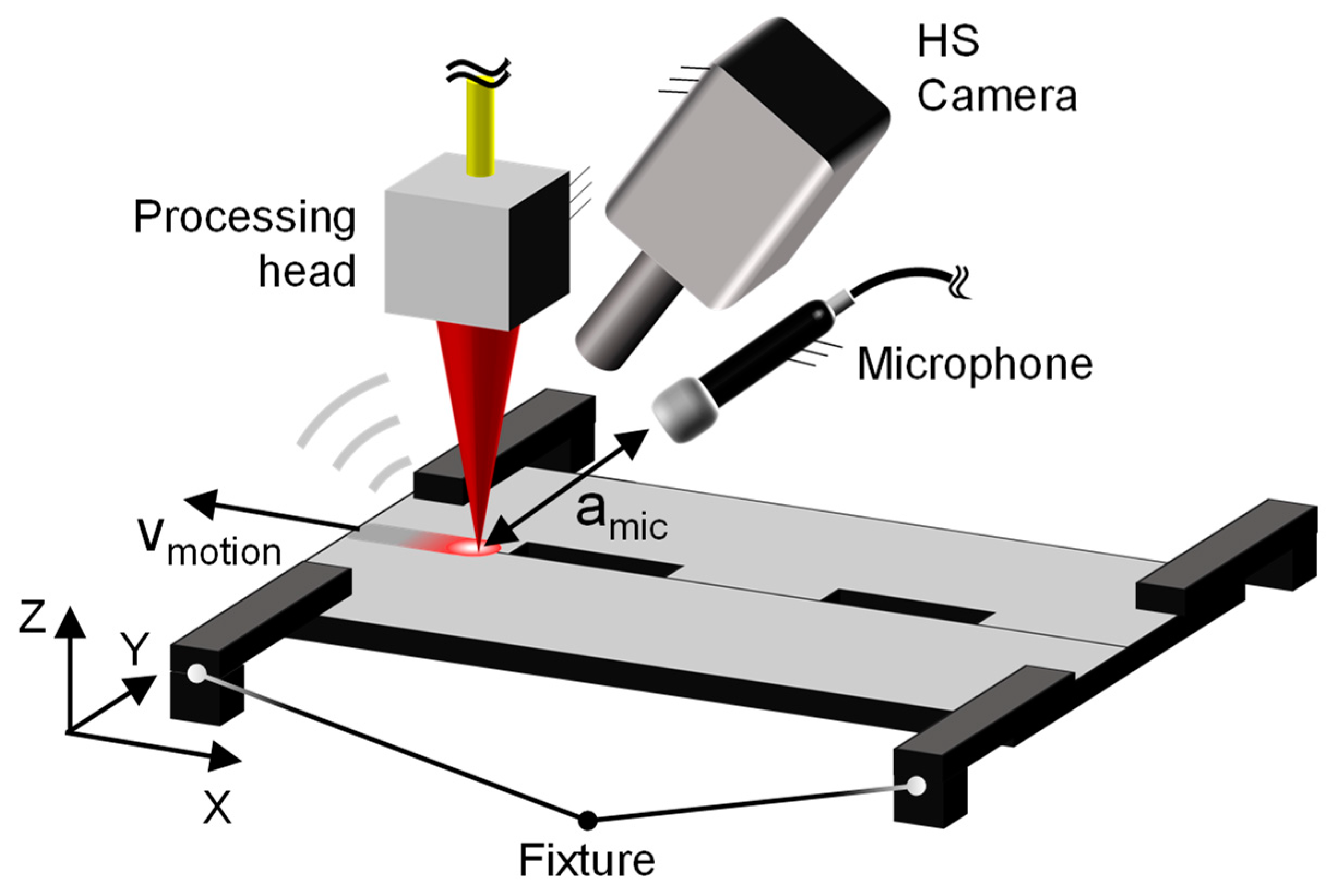
Figure 2). The specimens were clamped to the front of a six-axis robot (Kuka KR 60HA, Kuka AG, Augsburg, Germany), which was used for sample handling. All specimens were welded at a welding speed of
vw = 12 m/min using a laser power of
PL = 3.5 kW. The laser power was set for a full penetration. Microphones were mounted on the stationary processing head and oriented to the position of the laser-induced keyhole to record acoustic process emissions. Technical specifications are given in
Table 1. The AE sensor data were captured using a data acquisition system (Soundbook MK2, SINUS Messtechnik GmbH, Leipzig, Germany) operating with a sampling rate of 204.8 kHz per channel. A high-speed camera (SA-X2, Photron, Tokyo, Japan) equipped with a zoom lens (12X Zoom Lens System, Navitar, Ottawa, Canada) was used to record the process at 10 000 frames per second. The camera was positioned at an angle of approximately 85° to the specimen surface. A narrow band optical filter with a center wavelength of 808 nm was used to eliminate process emissions. The cross jet was turned off during the experiments to provide an idealized data acquisition. Each gap configuration (0.1 mm, 0.2 mm, and 0.3 mm) was repeated for 30 times to provide sufficient input for data processing.
Both microphones, the sE8 and the MK301, employed a sampling rate of 204.8 kHz for data acquisition. However, for the sE8 microphone, only frequencies up to 25.6 kHz were considered for further analysis since it is an audible range sensor. Additional information can be found in
Table 1.
3. Results
This section focuses on examining the impact of joint gap formation in laser beam butt welding. It will explore the data analysis of the acoustic signals produced during the welding process, specifically considering the relationship between the varying gap formations between metal sheets. Furthermore, an experimental design will be presented to investigate a classification system based on airborne acoustics. Finally, the obtained results will be discussed, providing plausible explanations for the observed phenomena.
3.1. Effect of Butt Joint Gap on Welding Process
3.1.1. Keyhole and Melt Pool Dynamics
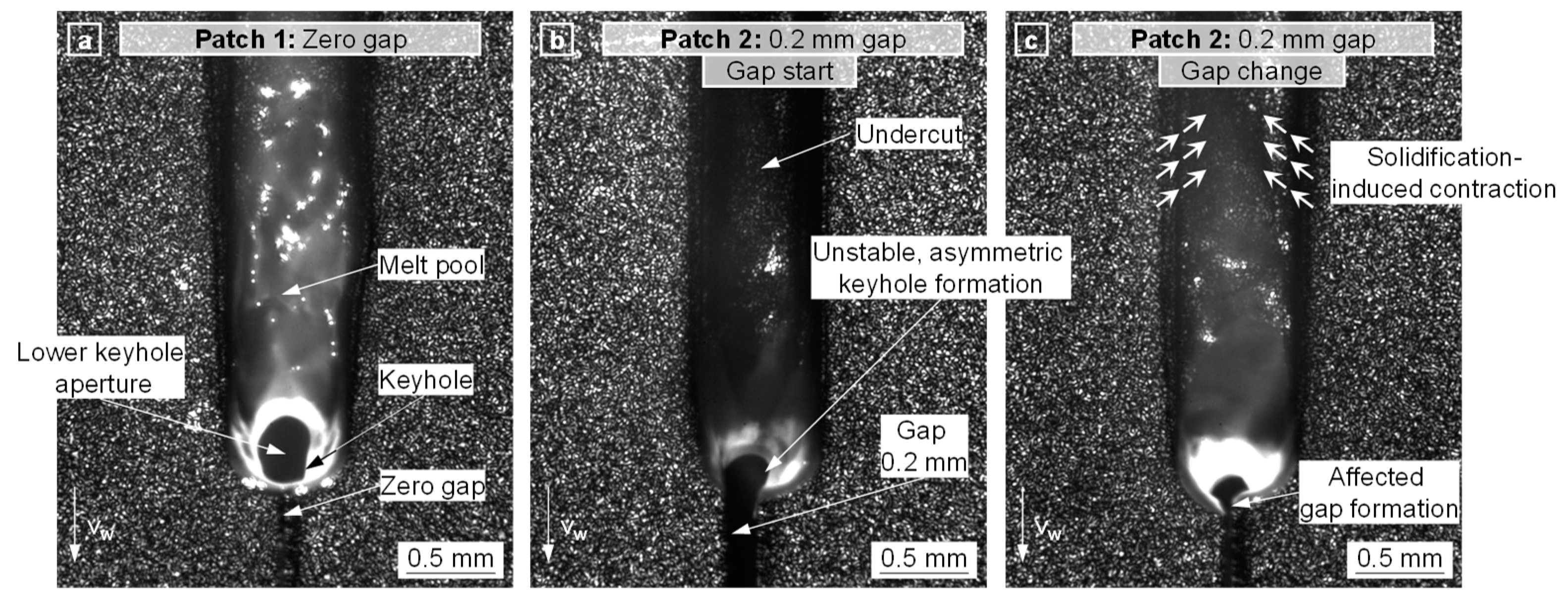
In order to correlate the acoustic signal with gap-related events in the welding process, the keyhole and melt pool dynamics were analyzed as a function of the gap using high-speed video recordings. Since the effect of a 0.1 mm gap size was negligible and the effects of 0.2 mm and 0.3 mm gaps were nearly identical,
Figure 3 shows only the effect of a 0.2 mm gap size as an example.
Patch 1 (zero gap, cf.
Figure 3a): During zero-gap welding, a stable energy input within the keyhole and a symmetrical weld seam formation were observed. The upper keyhole aperture was almost cylindrically shaped, while the lower keyhole aperture was slightly elongated in the welding direction. The resulting weld seam could be classified as defect-free.
Patch 2 (0.2 mm gap,
tframe = gap start, cf.
Figure 3b): At the start of the 0.2 mm gap patch, an unstable welding process with an asymmetric formation of the weld seam was observed, which resulted in a lack of fusion and shape deviations (e.g., weld seam undercuts) between the two sheets. A significant decrease in melt pool length was also observed.
Patch 2 (0.2 mm gap,
tframe > gap start, cf.
Figure 3c): By continuing the 0.2 mm gap patch, a change in the gap size and the corresponding keyhole and melt pool behavior was observed. Increasing weld lengths resulted in both an increase and an atypical decrease in gap size. The joint gap is formed during the welding process primarily due to process-induced strain (e.g., solidification-induced contraction of the weld), typically grows with an increasing weld length, and depends, among other things, on the sheet thickness, the welding speed, and the specimen fixture [
1,
3,
20]. The variation in gap size resulted in a deviating energy input as well as the formation of weld asymmetries.
Since the joint gap was found to have a significant effect on the keyhole and melt pool dynamics, it is conceivable that the gap also influences the acoustic emissions. Therefore, the following section gives an overview of the effected airborne sound.
3.2. Dataset Preparation
The welding experiments involved four distinct data classes: Zero Gap (zero gap), Gap 0.1 (0.1 mm gap), Gap 0.2 (0.2 mm gap), and Gap 0.3 (0.3 mm gap). Each experiment consisted of three patches of Zero Gap and two patches of Gap. The welding process for each patch lasted 160 ms without any delay between the transition from Zero Gap to Gap or vice versa. To remove the welding transition between consecutive patches, each patch recording was trimmed into segments with an onset and offset of 5 ms, resulting in a 150 ms recording per patch.
Utilizing the high-speed video recordings of the welding process (cf.
Figure 2), the estimation of the real gap size between all Zero Gap patches was made possible. These inspections unveiled the presence of unintended non-uniform gaps between the sheets, which can be attributed to the process-induced thermal expansion of molten metal [
21,
22] and the solidification-induced contraction of the weld seam after the welding process [
21,
22]. Leveraging the available additional gap information, interpolation techniques were employed to approximate the additional gaps for the Gap 0.1, Gap 0.2, and Gap 0.3 regions.
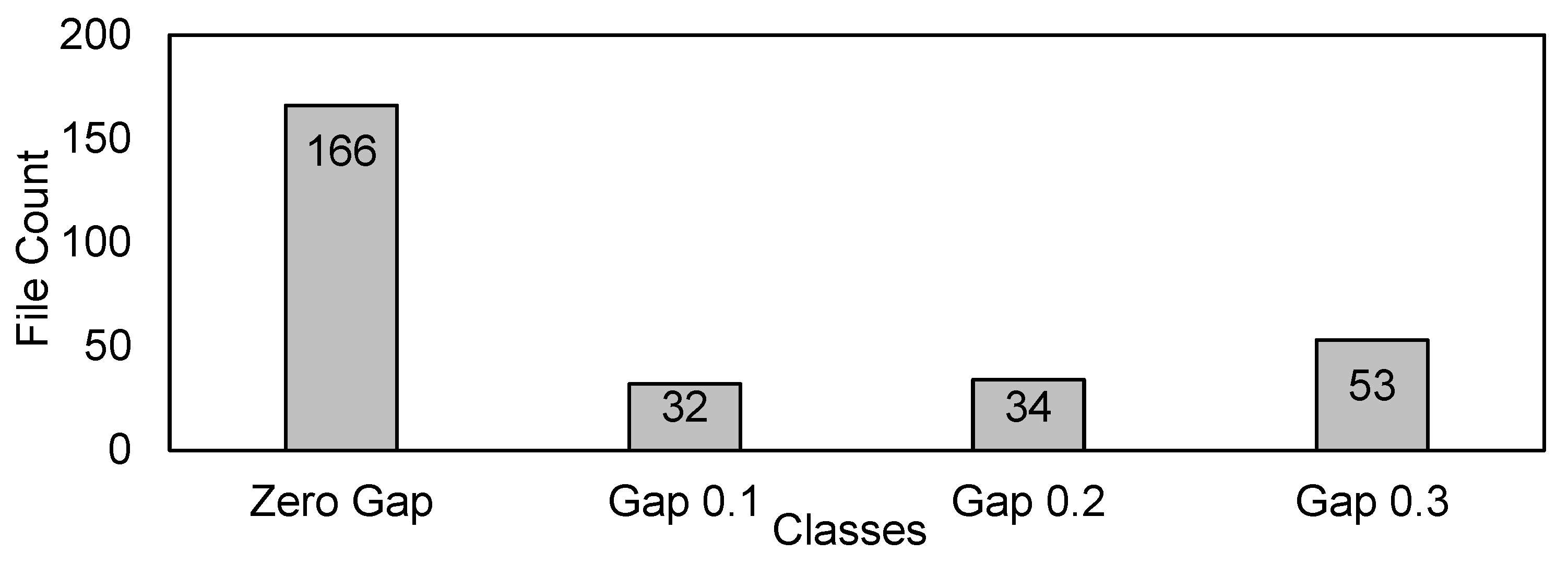
The presence of non-uniform gaps between the metal sheets in both Zero Gap and Gap patches resulted in mislabeling of the pre-labeled data. To tackle this problem, a threshold of 0.06 mm was established for the additional gap for Gap 0.1 and Gap 0.2 classes. Gap sizes greater than equal to 0.3 mm were considered as Gap 0.3. Up to this range, file count was significant. However, beyond 0.06 mm of additional gap, only a few files remained, and these were excluded from the dataset. Furthermore, it is important to note that these labels can be considered as soft labels due to the varying size range of gaps within each class.
Figure 4 provides a summary of the number of classes and the number of files per class that were utilized in this study. Additionally,
Table 2 presents the minimum and maximum range of actual gap sizes for each class.
3.3. Acoustic Emission
In this section, the data analysis of the airborne acoustic signals is discussed.
Figure 5 shows the amplitude spectrogram of a recorded acoustic signal from the weld process with and without gap formation, which is calculated using the Short Time Fourier Transform (STFT). The sound pressure of the acoustic signals emitted during the weld process may vary in terms of amplitude and bandwidth, depending on whether there is a zero gap or different gap sizes.
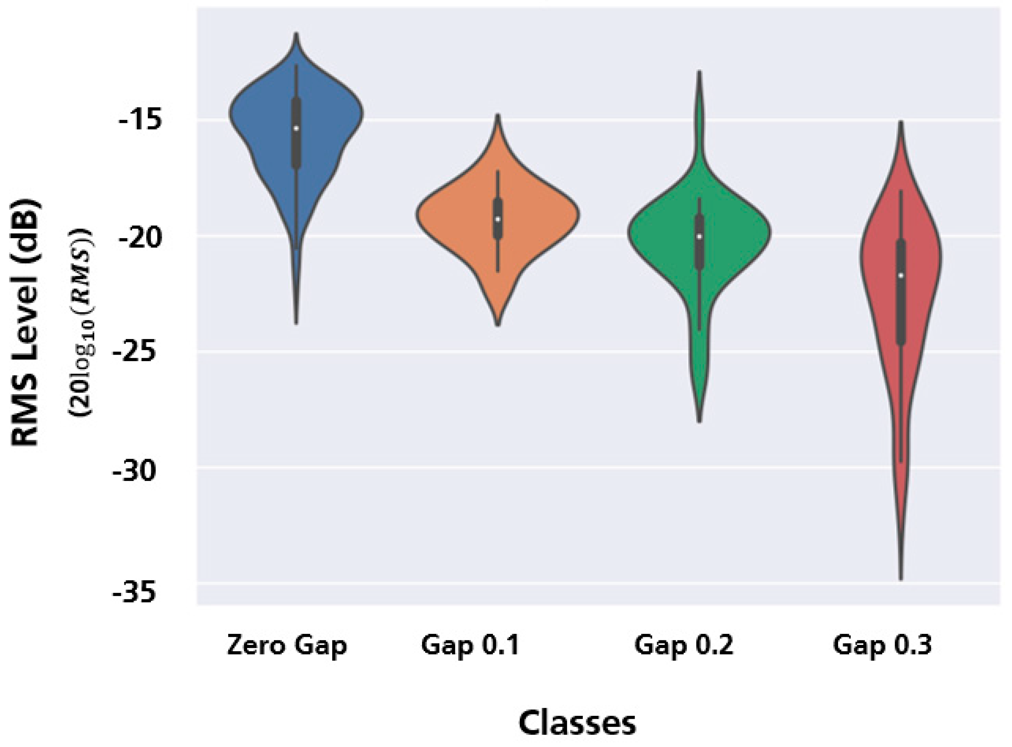
An exploratory data analysis was performed on the entire dataset to gain a better understanding of the Zero Gap and Gap classes. The analysis focused on average signal strength and the distribution of data within each class. The Root Mean Square (RMS) value was calculated from the audio samples to measure the differences between the sound classes. This involved squaring each sample, averaging the squared samples, and taking the square root of the result to obtain the RMS value. Additionally, the RMS values were converted to the decibel scale to make them more interpretable in physical terms.
The results showed that the RMS level of the signals varied based on the size of the gap between the metal sheets, as shown in
Figure 6. Specifically, as the gap size increased, there was a decrease in the RMS level. One possible explanation for this trend is that the reduced contact area between the metal sheet and the laser beam in the gap regions led to lower signal strength. However, accurately classifying the signals based on these RMS values posed a challenge due to the overlapping distributions observed between the Zero Gap and Gap classes.
Furthermore, the data distribution in terms of RMS level within each class can be observed on the y-axis. The Zero Gap class exhibited a distribution that was slightly skewed towards positive values. Gap 0.1 and Gap 0.2 followed a Gaussian distribution pattern. In contrast, Gap 0.3 showed a positive skew because a few data samples had lower RMS levels, likely due to larger gap sizes compared to the rest of the samples in that class. The median values of all Gap classes were similar to each other, but the Zero Gap class deviated from this pattern, as expected. This can be seen as a white dot in the center of the whisker in a violin plot.
3.4. Detection of Butt Joint Gaps
3.4.1. Experiment
Detecting and classifying the formation of gaps between metal sheets during the welding process using acoustics, specifically based on average signal strength, presents a considerable challenge due to the overlapping RMS levels between gap classes. To accurately identify and categorize the Zero Gap and Gap classes, it is necessary to employ neural networks in an automated detection and classification system. This system utilizes relevant time-frequency representations obtained through the STFT of the acoustic signals.
The experiments can be divided into two tiers. The first tier concentrates on detecting Zero Gap and Gap. The second tier aims to classify Gap sizes to determine the level of weld degradation based on the gap formation size. These assessments allow for effective evaluation of the informative nature of the segments without the need for direct measurement of their joint gap. Additionally, experiments were carried out to detect and classify data in both audible and ultrasonic frequency ranges. The following section offers a detailed explanation of the detection algorithm pipeline.
3.4.2. Detection Algorithm
This section discusses the details of the input data processing, neural network model design, and training scheme used to develop a classification model for the Zero Gap and Gap parameters. As the initial step in the classification process, audio data collected from the welding process undergoes feature extraction. The STFT is employed to calculate pertinent features, specifically magnitude spectrograms. This involves using specific parameters: an FFT size of 512, a Hann window size of 512, and a hop size of 256 samples. As a result, the spectrogram has a size of 29×257, consisting of 29-time frames and 257 frequency bins. To reduce the dynamic range, a logarithmic magnitude scaling is applied to the spectrograms. Additionally, the input features are normalized to have zero mean and unit variance per frequency band [
15].
In the subsequent step, the computed log-power spectrograms are fed into a CNN architecture previously explored in our research. Although CNNs are commonly used for computer vision tasks like image classification, they also prove valuable in audio analysis due to their hierarchical structure. CNNs can learn complex representations of the input, capturing both low-level features that encompass simple and localized patterns and high-level abstractions that encompass complex and global patterns, including shapes, objects, or specific attributes associated with the input data. Moreover, CNNs exhibit translation invariance, allowing them to identify patterns in the audio signal regardless of their precise location [
23].
The CNN architecture used in this work consists of two convolutional blocks, each with two 3×3 convolutional layers. Following each convolutional layer, a Rectified Linear Unit (ReLU) activation layer, a max-pooling layer, and a dropout layer are applied. A flatten layer is used before the fully connected layer to provide a one-dimensional representation of the data. Finally, a softmax layer serves as the classification layer to obtain the classification results as shown in
Figure 7.
The dataset was randomly shuffled to ensure a diverse representation of the data. It was then divided into three subsets: a training set, which contains 60% of the data and is used to train the model, a validation set, which consists of 20% of the data and is used to fine-tune the model and make decisions about its performance, and finally a test set, which also contains 20% of the data and is used to evaluate the trained model performance. To address the issue of class imbalance in the dataset, the SMOTE was employed [
16]. This involved increasing the number of data samples in the training and validation sets by interpolating feature vectors between existing minority class samples to match the count of the majority class file. Additionally, to ensure a robust evaluation of the model’s performance, a 5-fold cross-validation strategy was employed. In this strategy, the dataset is divided into five subsets to ensure robust evaluation of the model's performance. Each subset is used as validation set while the remaining four subsets are combined to form the training set. Further, to improve the robustness of the classification model, mixup data augmentation is applied to the log spectrograms [
11]. Mixup data augmentation creates synthetic training samples by blending pairs of training data points, which helps to regularize the model and improve its ability to generalize to unseen data by fostering smooth interpolation between different classes. We train the CNN model using Adam Optimizer with categorical cross-entropy loss for 300 epochs, with the learning rate of 10
–3. Due to the limited size of the dataset, the model is susceptible to overfitting, which occurs when the model excessively tailors itself to the training data and fails to generalize well to new, unseen data. To mitigate this issue, the training process incorporates the early stopping technique with a patience parameter set to 50 epochs [
24]. This implies that the training will terminate if the model's performance on the validation dataset fails to exhibit improvement for 50 consecutive epochs. By employing this approach, the model is safeguarded against overfitting and gains the ability to generalize effectively to unseen data.
3.4.3. Detection Results
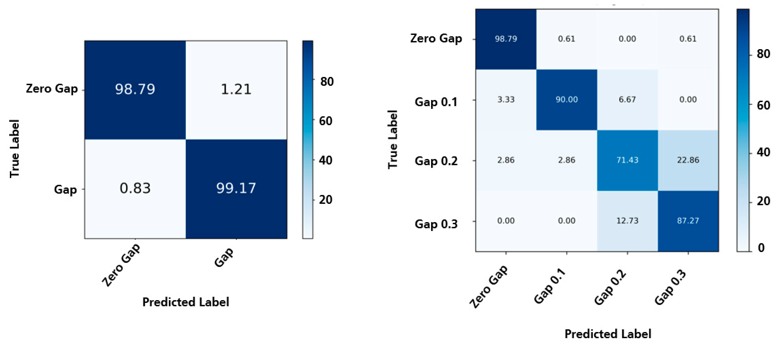
Initially, a binary classification task was conducted to differentiate between those data samples with gaps and those without gaps. This involved merging all gap classes (such as Gap 0.1, Gap 0.2, Gap 0.3) into a single category, while considering the Zero Gap class as a separate category. When applied to the audible range sensor dataset, the resulting accuracy on the test set averaged at 98.9% per file for binary classification. Subsequently, a multiclass classification task was performed to achieve a more detailed classification, see
Figure 8. In this case, each Gap class was treated as a distinct category. The model achieved an average file-wise accuracy of 86.8%.
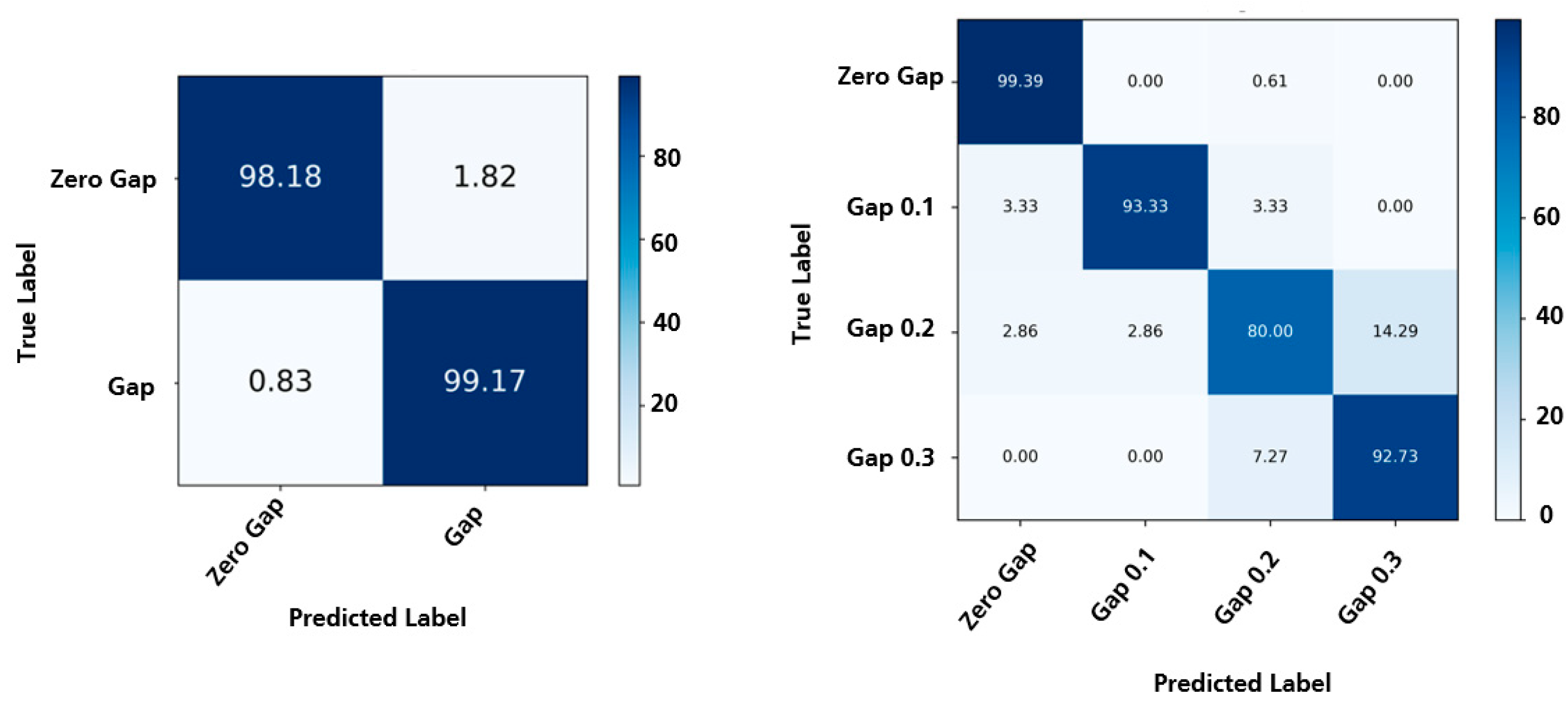
For the ultrasonic range sensor dataset, the resulting accuracy on the test set averaged 98.6% per file for binary classification, which was similar to the performance observed in the audible range dataset. Subsequently, a multiclass classification task was carried out to achieve a more granular classification. The model achieved an average file-wise accuracy of 91.4%, indicating a significant improvement (4.6% accuracy) compared to the audible range dataset, see
Figure 9. It is worth noting that the improvement in performance observed in the multiclass classification for the ultrasonic range dataset could potentially be attributed to factors such as the wider frequency band or the positioning of the microphone.
The confusion matrices depicted in
Figure 8 and
Figure 9 illustrate noticeable misclassifications between Gap 0.2 and Gap 0.3 during the multiclass classification process. This misclassification could potentially be attributed to the minimal disparity in the acoustic emission characteristics between the Gap 0.2 and Gap 0.3 classes, as well as the limited number of data samples available in the test set. It is highly probable that by augmenting the training data with additional samples, providing accurate annotations, and further optimizing the model, significant improvements can be achieved in the classification results. These improvements would be evident through the analysis of a substantial amount of test data.
While the results presented in this paper appear promising, it is important to note that the classification outcomes are confined to the specific dataset utilized. As a result, this model may not be readily applicable or generalize well to real-world applications. However, by fine-tuning the feature and model parameters, it is possible to obtain more reliable and accurate results.
4. Conclusion
Laser beam butt welding of metal sheets made of high-alloy steel is a technically challenging task, mainly due to the formation of joint gaps that can cause weld defects, such as a lack of fusion, undercuts, or seam sagging. To address this, it is crucial to develop new monitoring methods to accurately track the size of the gaps and detect any potential defects in the seam. This study aims to investigate methods for monitoring acoustic processes, which contribute to the comprehension of different process parameters, such as gap sizes between metal sheets, and the acoustic emissions produced during welding. This includes the utilization of microphones that can detect audible and ultrasonic range signals. By developing methodologies and algorithms for extracting meaningful features and analyzing the signals, it becomes feasible to implement automated acoustic process monitoring using neural networks. This monitoring approach can effectively detect butt joint gaps. Furthermore, the classification results suggest that utilizing ultrasonic range acoustic signals may yield better outcomes compared to audible range signals. However, it is important to note that the results of this study cannot be generalized to all similar use-cases due to limitations in the dataset. To enhance the detection rates and overall reliability of the monitoring system, further experimental and analytical investigations are required. These efforts will help expand the dataset and enable the application of the findings in real-world scenarios, accounting for acoustic interactions with common disturbances encountered in industrial settings, such as cross jet.
Author Contributions
Conceptualization, S.G., L.S., F.R., K.S., S.K., D.B., T.K., A.K., J.P.B. and J.B.; formal analysis, S.G., L.S., T.K., A.K.; data curation, S.G., T.K., A.K., L.S.; writing—original draft preparation, S.G. and L.S.; writing—review and editing, F.R., K.S., B.S., J.P.B., J.B.; visualization, S.G., L.S. All authors have read and agreed to the published version of the manuscript.
Funding
This research was part of “Leistungszentrum InSignA”, funded by Thuringian Ministry of Economics, Science and Digital Society (TMWWDG), grant number 2021 FGI 0010, and by the Fraunhofer-Gesellschaft, grant numbers 10-05014, 40-04115.
Data Availability Statement
Not applicable.
Acknowledgments
The authors would like to acknowledge the support received from the Fraunhofer Internal Programs under Grant No. Attract 025-601128. Additionally, we extend our gratitude to the Fraunhofer IZFP and IDMT projects for their cross-support in facilitating the completion of this research.
Conflicts of Interest
The authors declare no conflict of interest.
References
- Hsu, R.; Engler, A.; Heinemann, S. The gap bridging capability in laser tailored blank welding. International Congress on Applications of Lasers & Electro-Optics 1998, 1998, F224–F231. [Google Scholar] [CrossRef]
- Kroos, J.; Gratzke, U.; Vicanek, M.; Simon, G. Dynamic behaviour of the keyhole in laser welding. Journal of Physics D: Applied Physics 1993, 26, 481. [Google Scholar] [CrossRef]
- Walther, D.; Schmidt, L.; Schricker, K.; Junger, C.; Bergmann, J.P.; Notni, G.; Mäder, P. Automatic detection and prediction of discontinuities in laser beam butt welding utilizing deep learning. Journal of Advanced Joining Processes 2022, 6, 100119. [Google Scholar] [CrossRef]
- Schricker, K.; Schmidt, L.; Friedmann, H.; Diegel, C.; Seibold, M.; Hellwig, P.; Fröhlich, F.; Bergmann, J.P.; Nagel, F.; Kallage, P.; et al. Characterization of keyhole dynamics in laser welding of copper by means of high-speed synchrotron X-ray imaging. Procedia CIRP 2022, 111, 501–506. [Google Scholar] [CrossRef]
- Schmidt, L.; Römer, F.; Böttger, D.; Leinenbach, F.; Straß, B.; Wolter, B.; Schricker, K.; Seibold, M.; Pierre Bergmann, J.; Del Galdo, G. Acoustic process monitoring in laser beam welding. Procedia CIRP 2020, 94, 763–768. [Google Scholar] [CrossRef]
- Huang, W.; Kovacevic, R. Feasibility study of using acoustic signals for online monitoring of the depth of weld in the laser welding of high-strength steels. Proceedings of the Institution of Mechanical Engineers, Part B: Journal of Engineering Manufacture 2009, 223, 343–361. [Google Scholar] [CrossRef]
- Nicolas, A.; Enzo, T.; Fabian, L.; Ryan, S.; Vincent, B.; Patrick, N. Coupled membrane free optical microphone and optical coherence tomography keyhole measurements to setup welding laser parameters. In Proceedings of the Proc.SPIE; 2020; p. 1127308. [Google Scholar]
- Li, L. A comparative study of ultrasound emission characteristics in laser processing. Applied Surface Science 2002, 186, 604–610. [Google Scholar] [CrossRef]
- Le-Quang, T.; Shevchik, S.A.; Meylan, B.; Vakili-Farahani, F.; Olbinado, M.P.; Rack, A.; Wasmer, K. Why is in situ quality control of laser keyhole welding a real challenge? Procedia CIRP 2018, 74, 649–653. [Google Scholar] [CrossRef]
- Wasmer, K.; Le-Quang, T.; Meylan, B.; Vakili-Farahani, F.; Olbinado, M.P.; Rack, A.; Shevchik, S.A. Laser processing quality monitoring by combining acoustic emission and machine learning: a high-speed X-ray imaging approach. Procedia CIRP 2018, 74, 654–658. [Google Scholar] [CrossRef]
- Zhang, H.; Cisse, M.; Dauphin, Y.N.; Lopez-Paz, D. mixup: Beyond empirical risk minimization. arXiv 2017, arXiv:1710.09412 2017. [Google Scholar]
- Park, D.S.; Chan, W.; Zhang, Y.; Chiu, C.-C.; Zoph, B.; Cubuk, E.D.; Le, Q.V. Specaugment: A simple data augmentation method for automatic speech recognition. arXiv 2019, arXiv:1904.08779 2019. [Google Scholar]
- Chawla, N.V.; Bowyer, K.W.; Hall, L.O.; Kegelmeyer, W.P. SMOTE: synthetic minority over-sampling technique. Journal of artificial intelligence research 2002, 16, 321–357. [Google Scholar] [CrossRef]
- Wang, J.C.; Lee, H.P.; Wang, J.F.; Lin, C.B. Robust Environmental Sound Recognition for Home Automation. IEEE Transactions on Automation Science and Engineering 2008, 5, 25–31. [Google Scholar] [CrossRef]
- Johnson, D.S.; Grollmisch, S. Techniques improving the robustness of deep learning models for industrial sound analysis. 2020. [CrossRef]
- Mesaros, A.; Heittola, T.; Benetos, E.; Foster, P.; Lagrange, M.; Virtanen, T.; Plumbley, M.D. Detection and Classification of Acoustic Scenes and Events: Outcome of the DCASE 2016 Challenge. IEEE/ACM Transactions on Audio, Speech, and Language Processing 2018, 26, 379–393. [Google Scholar] [CrossRef]
- Jing, L.; Zhao, M.; Li, P.; Xu, X. A convolutional neural network based feature learning and fault diagnosis method for the condition monitoring of gearbox. Measurement 2017, 111, 1–10. [Google Scholar] [CrossRef]
- Alzubaidi, L.; Zhang, J.; Humaidi, A.J.; Al-Dujaili, A.; Duan, Y.; Al-Shamma, O.; Santamaría, J.; Fadhel, M.A.; Al-Amidie, M.; Farhan, L. Review of deep learning: concepts, CNN architectures, challenges, applications, future directions. Journal of Big Data 2021, 8, 53. [Google Scholar] [CrossRef] [PubMed]
- Hershey, S.; Chaudhuri, S.; Ellis, D.P.W.; Gemmeke, J.F.; Jansen, A.; Moore, R.C.; Plakal, M.; Platt, D.; Saurous, R.A.; Seybold, B.; et al. CNN architectures for large-scale audio classification. In Proceedings of the IEEE International Conference on Acoustics, Speech and Signal Processing (ICASSP); 2017; pp. 131–135. [Google Scholar]
- Simon, F.B.; Nagel, F.; Hildebrand, J.; Bergmann, J.-P. Optimization strategies for welding high-alloy steel sheets. In Proceedings of the Simulationsforum 2013; 2013; pp. 189–200. [Google Scholar]
- Sudnik, W.; Radaj, D.; Erofeew, W. Computerized simulation of laser beam weld formation comprising joint gaps. Journal of Physics D: Applied Physics 1998, 31, 3475. [Google Scholar] [CrossRef]
- Seang, C.; David, A.K.; Ragneau, E. Nd:YAG Laser Welding of Sheet Metal Assembly: Transformation Induced Volume Strain Affect on Elastoplastic Model. Physics Procedia 2013, 41, 448–459. [Google Scholar] [CrossRef]
- Kayhan, O.S.; Gemert, J.C.v. On translation invariance in cnns: Convolutional layers can exploit absolute spatial location. In Proceedings of the IEEE/CVF Conference on Computer Vision and Pattern Recognition; 2020; pp. 14274–14285. [Google Scholar]
- Prechelt, L. Early Stopping - But When? In Neural Networks: Tricks of the Trade; Orr, G.B., Müller, K.-R., Eds.; Springer: Berlin, Heidelberg, 1998; pp. 55–69. [Google Scholar]
|
Disclaimer/Publisher’s Note: The statements, opinions and data contained in all publications are solely those of the individual author(s) and contributor(s) and not of MDPI and/or the editor(s). MDPI and/or the editor(s) disclaim responsibility for any injury to people or property resulting from any ideas, methods, instructions or products referred to in the content. |
© 2023 by the authors. Licensee MDPI, Basel, Switzerland. This article is an open access article distributed under the terms and conditions of the Creative Commons Attribution (CC BY) license (http://creativecommons.org/licenses/by/4.0/).
