1. Introduction
The latest IPCC report [
1] has highlighted the urgent need to decarbonize industry, buildings, and transport. In addition to electricity, hydrogen produced from renewable resources presents itself as a good energy vector [
2,
3] to decabonate industry, transport, and building of the future in a cleaner energy mix based on renewable energies and nuclear. To convert the chemical energy of hydrogen to electrical energy, fuel cells can be used. Supplied by hydrogen, fuel cells convert chemical energy into electricity and heat by means electrochemical reactions, emitting only water.
Proton Exchange Membrane Fuel Cells (PEMFCs) are the most developed and commercialized. PEMFCs have advantages as low operating temperature, high energy conversion efficiency, and swift start-up. PEMFC cells are stacked to form a stack.
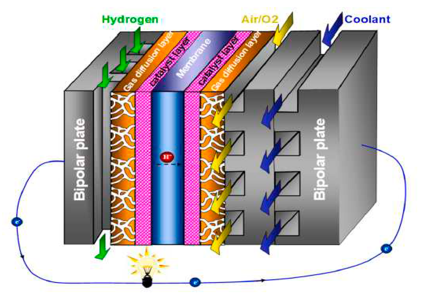
Figure 1 shows a single PEM fuel cell. consists of a polymer electrolyte membrane (PEM), two catalyst layers (CL), two sets of gas diffusion layers (GDL) and microporous layers (MPL), and two bipolar plates (BP) that contain gas flow channels (GFC) and possibly a cooling flow field. In the anode LC, hydrogen separates into protons (hydrogen ions) and electrons: the former pass through the PEM to the cathode LC, while the latter are conducted to the cathode LC via the output circuit. In the cathode, ambient air is introduced into the GFC, with oxygen diffusing via the GDL/MPL to the LC, where the oxygen reacts with protons and electrons from the anode LC to produce water. In order to increase the air pressure and control the stoichiometry and depending on the power output a compressor can be used. The hydrogen oxidation reaction (HOR) occurs in the anode LC:
In the cathode CL, the oxygen reduction occurs:
The PEMFC lifespan, safe-use and performance are greatly impacted by the operating temperature. The maximum operating temperature of a PEMFC should not exceed 90 °C. The optimal operating temperature of PEMFC is around 80°C [
5]. Therefore, a highly efficient PEMFC Thermal Management System is required to ensure that fuel cells operate under optimal conditions to improve performance and fuel cell lifespan.
Several technologies are used to manage the thermal management of the PEMFCs and avoid an excessive rise in temperature in the fuel cell. There are two ways to decrease the PEMFC temperature: internal modification at materials and chemistry of the fuel cell to reduce the heat generation or external thermal management system to enhance the heat dissipation from the fuel cell [
6]. External management systems are air circuits, coolant circuit, heat pipes or the use of PCM and PCM composites [
7,
8]. Currently, liquid cooling systems are the most widely used. The main problems with those systems are their cost, their complex implementation and their lack of reliability. Passive thermal management systems through the use of Heat pipes or Phase Change Materials, is an attractive way to achieve PEMFC thermal management and ensure that the PEMFC temperature remains within the desired range.
The present paper present a critical review on thermal management systems for PEMFC using passive systems.
2. Thermal phenomena in PEMFC
2.1. Heat sources in PEMFC
The heat generated by a pemfc is the result of several mechanisms: entropic heating, irreversible heating due to electrochemical reactions, joule heating due to ohmic resistance, and water phase changes [
11,
12,
13,
14]. Entropic heat can account for 30% of the total heat produced, and is generated by entropy changes in electrochemical reactions. It can be expressed by:
where j is the transfer current density, and Uo the equilibrium potential. The irreversibility of the electrochemical reactions due to presence of the overpotential in the CLs contributes a major portion of heat generation, which may account for 60% of total heating [
2]. It’s can be expressed by [
15,
16,
17,
18]:、
Joule heat accounts for around 10% of total heat generated. It results from both ionic and electrical resistances. Its expression is given by:
During operation, water may be subject to a phase change, resulting in the release or absorption of latent heat.
The total heat sources in PEMFC can be expressed as the sum or the entropic heat, irreversible heat, joule heat and phase change heat.
2.2. Thermophysical properties of PEMFC compounds
The heat transfer within a PEMFC depends on the thermo-physical properties of the different components that constitute it and the dimensions of these components. The heat transfer modes in a PEMFC are mainly: conduction, convection and conjugated conduction-convection.
Table 1,
Table 2,
Table 3 and
Table 4 summarizes, respectively, the thermophysical properties and heat transfer modes of membrane, GDL and MPL, CL and BP.
2.3. Heat transfer in PEMFC
In a PEMFC, about 55% to 40% of the chemical energy of the hydrogen is converted into heat. This heat must be removed to keep a safe and sustainable operation. Evacuate it; active or passive systems can be used. The heat is generated in the MEA assembly and dissipated via the bipolar plates. This leads to a temperature gradient in a PEM cell. The dominant mode of heat transfer is thermal conduction. By applying the Fourier equation, the temperature through-plane variation at CL becomes:
Applying the same approach using the same assumptions,
and
can be estimated using the following equations:
A minor part of the generated heat is removed by GFC.
is the ratio of heat generated to heat removed by the GFC flow [
5,
13]:
For a stoichiometry of 1.5, is less than 5%.
The heat that is not removed by GFC, it is removed by conduction through the GDL, CL and BP. The heat transfer can be modeled with two thermal resistors in series.
3. Thermal modeling of PEMFC
The purpose of thermal modeling of a PEMFC is to develop models with the best compromise between simplicity and accuracy. Thermal phenomena in a PEMFC are coupled with charge and mass transfers. In the literature, two thermal modeling methods exist for PEM fuel cells [
14]. The models couple electrochemistry and thermal [
15,
16], and the models are based on a pure heat balance in which only the main heat generation (obtained from the losses) is taken into account. The coupling models of electrochemistry and thermal give -in general- good accuracy and robustness at the local scale and the possibility to simulate in two or three dimensions. However, the coupling of electrochemistry and thermal requires a good knowledge of the PEMFC (porosity of the electrodes, concentration, chemistry of the electrolyte, dimensions of the particles etc...) and it is sometimes very difficult to be able to characterize the electrochemical and thermal aspects finely. They are numerically heavy; the calculation times for these types of models are very often long and require significant computing power.
Cell voltage
The characteristic curve of a fuel cell gives the voltage response of the cell as a function of current density. Models in the literature that predict voltage as a function of current density are classified into two groups: based on the solution of charge conservation equations and semi-empirical models [
17,
18,
19,
20,
21,
22]. Semi-empirical models are simple and the parameters in these models can be easily adjusted to the experimental data for better accuracy. The cell voltage can be estimated from the reversible voltage by subtracting overpotentials terms: activation, ohmic and concentration.
The reversible potential can be calculated by Nernst equation [
14]:
Considering the different losses [
14]:
3.1. Activation overpotential
The estimation of activation overpotentiel can be done by the Butler-Volmer equation [
14]:
3.2. Ohmic overpotential
The ohmic overpotential is the result of protonic and electronic resistances across the cell [
14].
Protonic conductivity can be estimated by [
23]:
3.3. Concentration overpotential
Concentration overpotential is caused by a decrease in the concentrations of the reactants [
24].
The limiting current is often a constant.
Applying energy conservation laws, the heat generated by a PEMFC stack can be expressed as :
With Ncell is the number of fuel cells.
4. Thermal management
As we have seen before, there are many thermal problems in a PEMFC. Therefore, the thermal management of PEMFC is essential to ensure better performance, autonomy and optimal life [
5,
25,
26]. A distinction is made between cooling and cold start techniques.
There are various PEMFC cooling techniques. These techniques can be passive, active or hybrid. The study carried out by Wang et al [
27] showed that thermal management represents around 8% of the cost of the PEMFC system. There are two constraints to consider when opting for a cooling technology: cost and performance improvement. Low powers (< 100 W) requires a high stoichiometric air ratio for cooling [
28]. However, increasing air stoichiometry leads to membrane drying [
28]. When PEMFC power is between 200 W and 2 kW, reactive and cooling air separation is required. Above 2 kW, liquid cooling is generally used [
29].
4.1. Active cooling systems
Liquid cooling techniques are the most common in medium and high power PEMs, especially in PEMFC vehicles [
5,
30]. The great advantage of air cooling systems is their simplicity. The low thermal conductivity and heat capacity of air reduces its efficiency and limits its use for medium and high powers. Liquids have better thermophysical properties than air: density, thermal conductivity and heat capacity. For powers above 10kW, liquid cooling systems are widely used [
5].
Liquid cooling systems generally consist of a closed (sealed) liquid circulation circuit, a pump to circulate the liquid and an exchanger to remove the heat absorbed by the liquid. The most commonly used liquids are water, glycols, oils and acetone [
5]. Liquid cooling systems are more efficient than air cooling systems. Indeed, the liquids generally used have a higher specific heat capacity than air. However, they are much more complex and expensive. Indeed, these systems generally include a pump, a piping network and a container for the coolant to avoid leakage. They are also more expensive in terms of maintenance.
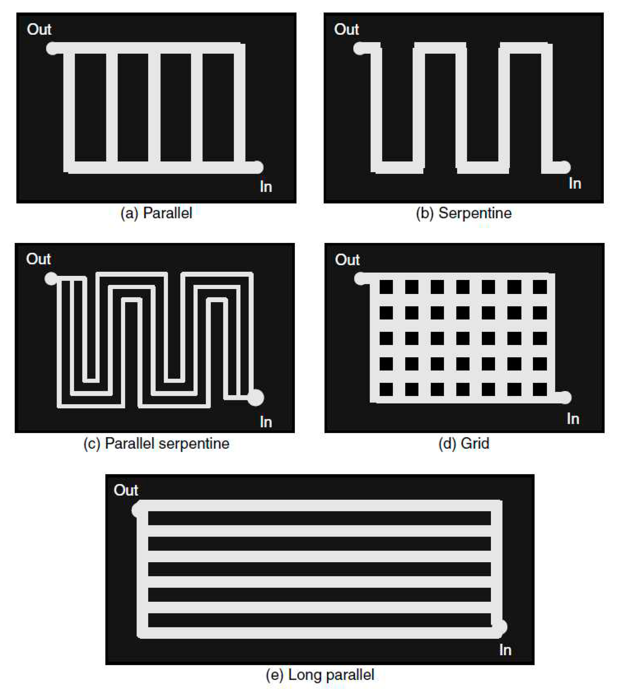
In liquid cooled PEMFC the coolant through cooling channels. Cooling channels are usually etched on the BPs. The cooling channels are usually made by etching processes on the bipolar plates. Most of the heat generated at the electrodes is transmitted by conduction to the bipolar plates. By forced convection, the bipolar plates transmit this heat to the cooler. The liquid cooling is controlled and driven by convection between the cooler and the bipolar plates. As this convection exchange occurs in the cooling channels, their geometrical shapes and designs play an important role on the thermal performance of the stack. In the literature extensive studies have been carried out to optimize the design of the channels, to analyze and control the impact of the flow field on the cooling of the stack. The most applied configurations are mainly four: parallel-like, serpentine-like, 2D wavy-like with multi-pass and 3D fine mesh flow. In the industry, there are parallel flow channels in ballard stacks, wavy flow channels in Honda stacks and similar 3D mesh coolant flow channels are adapted by Toyota. The parallel flow channel is also known as a straight channel. It is distinguished by its fabrication simplicity but with a reduced cooling efficiency.
Figure 2.
Different flow fields [
31].
Figure 2.
Different flow fields [
31].
Recently, several works have focused on improving and optimizing liquid cooling systems. The main ways to improve the performance of these systems are design optimization, improvement, and optimization of the material properties of the bipolar plates and coolants used [
32,
33,
34,
35,
36,
37].
4.2. Passive cooling systems
In general, passive thermal management systems are classified into three groups: Liquid (liquid-vapor phase change) systems, heat pipes and PCMs.
The advantages of passive cooling systems comparing to active systems: low energy consumption, more temperature uniformity and low costs.
4.2.1. Heat pipes
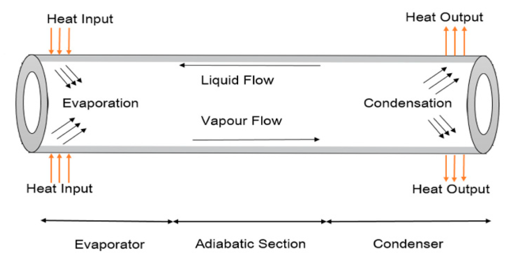
Flat heat pipes, tubular heat pipes and pulsed heat pipes are the main types of heat pipes. A heat pipe is a hermetic enclosure that contains a fluid in a state of liquid-vapor equilibrium. At the end of the heat pipe located near the cell to be cooled, the fluid in a liquid state vaporizes by absorbing thermal energy emitted by the hot source. The vapor then flows through the heat pipe to the other end located at a cooling system, which in many cases is the ambient air where it condenses to return to the liquid state. The condensation allows to give thermal energy to the cold source (often the ambient air). The liquid must then return to the evaporator, using the forces of gravity [
38,
39].
Figure 3 present a conventional heat pipe.
Works reviewed have shown that heat pipes can considerably reduce the energy consumption of cooling systems by up to 30% on the overall energy balance. Heat pipes provide a more uniform temperature field than active systems. Works on improving heat pipe systems focuses on the working fluid, geometric shapes and materials. the table shows the articles reviewed in this article. Heat pipes can present a space problem at the scale of a stack. In the literature, several works have focused on the development of solutions with micro heat pipes.
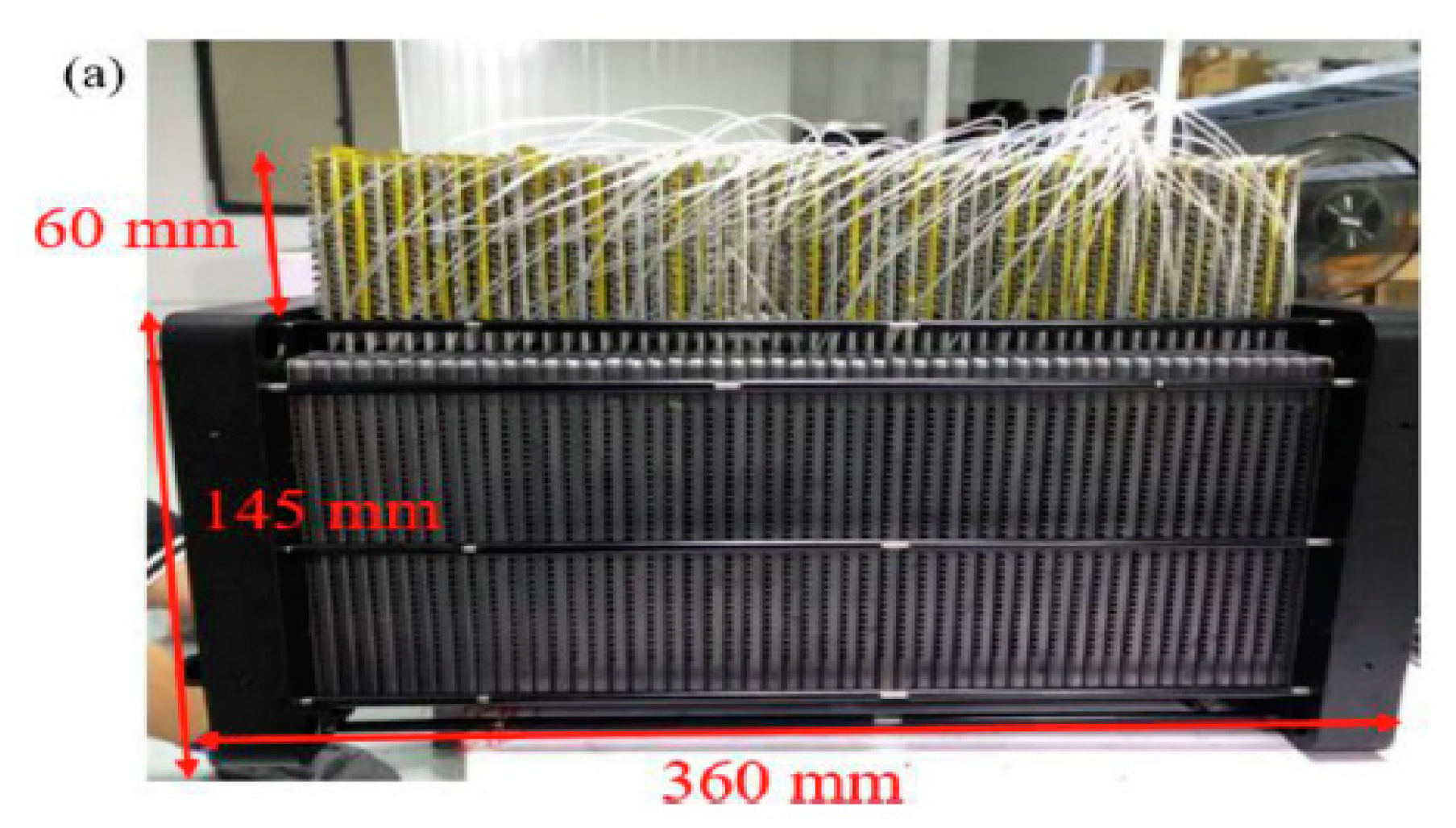
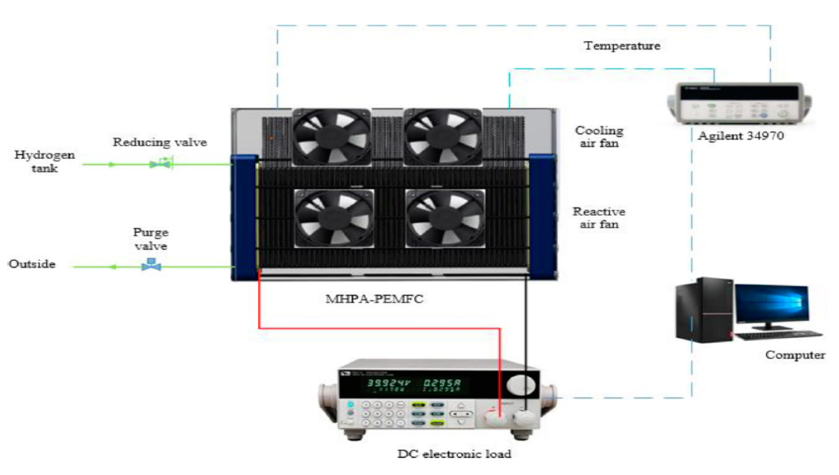
Recently Wang et al [
40] conducted experimental study on the use of mico heat pipes arrays (MPHA) for PEMFC thermal management. The MPHA was integrated in the bipolar plates. Fans used to cooling condensing zone. A photo of MPHA- PEMFC is presented in
Figure 4 [
40]. The experimental setup is presented in
Figure 5. The results showed that the proposed thermal management system has a short thermal response time between 600 and 900s. Used MPHA allow to have a temperature field more uniform.
Figure 4.
The PMHPA- PEMFC developed in [
40].
Figure 4.
The PMHPA- PEMFC developed in [
40].
Table 5.
crtical review of heat pipes for PEMFC.
Table 5.
crtical review of heat pipes for PEMFC.
| Num |
Years |
Authors |
Heat pipes type |
Research content |
Main conclusion |
| 1 |
2023 |
Wang et al [40] |
Micro heat pipes arrays (MHPA) |
|
The system has shot thermal response time, between 600 -900s. The temperature field in the MHPA evaporation zone, adiabatic zone, and condensation zone are relatively uniform Good heat transfer performance Energy consumption reduction about 25,66% comparing to conventional air-cooling systems |
| 2 |
2023 |
Yang et al [41] |
Micro heat pipes arrays |
|
|
| 3 |
2023 |
Hang et al [42] |
Ultra-thin flat heat pipes (UTFHP) |
In order to reduce the volume of heat pipe cooled stack, a novel design of heat pipe bipolar plates was proposed. 3D numerical model was developed Thermal performances of HPBP and UTFHP was compered. |
|
| 4 |
2022 |
Min et al [43] |
Pulsating heat pipe (PHP) |
|
Studied PHP cooling system can reduce PEMFC temperature by 36.5°C.
Comparing to liquid system, PHP system allow to have a temperature distribution more uniform |
| 5 |
2020 |
Huang et al [44] |
Flat-plate heat pipe (FPHP) |
A PEMFC-FPHP stack was fabricated, assembled and tested Experimental analysis Investigation of the effect of gravity on the temperature distribution of PEMFC- FPHP Study of the effect of inclination of the PEMFC-FPHP stack on their thermal performance |
|
| 6 |
2013 |
Clement et al [45] |
Pulsating heat pipe |
Design, sizing and fabrication of pulsating heat pipes integrated in the PEMFC bipolar plates Different working fluids were tested : acetone, methanol, and deionized water |
|
| 7 |
2021 |
Huang et al [46] |
Ultra-thin vapor chambers |
|
|
4.3. Phase change materials (PCMs)
Many research was focused in the use of PCM composites for li-ion batteries thermal management but few research on the use of these composites for PEM fuel cell thermal management [
47,
48]. PCMs have the ability to store and release a large amount of heat at the time of phase change in reduced volumes [
49,
50,
51]. In fact, when the PCM is in the solid phase and the temperature rises to the melting temperature, it will become liquid and stores energy. Similarly, when it is in the liquid phase and the temperature drops below its melting point, it will become liquid again and releases the stored energy.
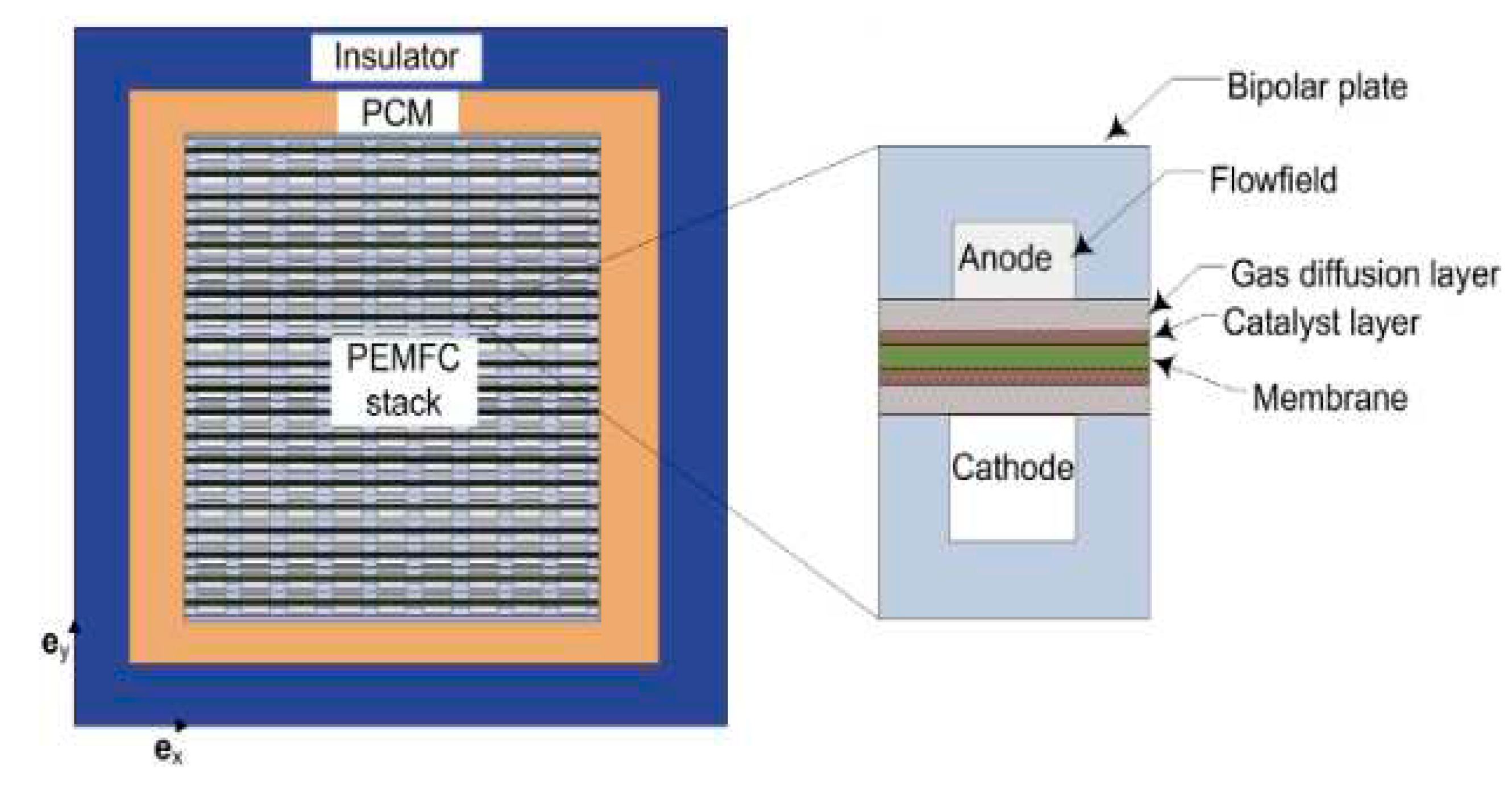
The use of PCMs for passive thermal management of PEM fuel cells has been studied by Sasmito et al [
52]. The authors studied the application of PCM for PEM fuel cell stack thermal management under cold weather conditions. A 2D numerical model has been developed. The PCM model was validated by comparison with experimental data. Four possible configurations were considered: stack without any additional insulation, stack with thermal insulator only, stack with PCM only, and stack with combination of PCM and thermal insulator. Parametric studies on the impact of the thickness of the insulator and the PCM used, the type of PCM, the ambient temperature, the convective exchange coefficient, and the PCM on start-up conditions have been done. The results showed that using a PCM combined with an insulator allows for keeping the stack's temperature above freezing for two days. Among the parameters studied, the ambient temperature is the parameter that has the greatest impact on storage duration.
Figure 6.
Computational domain studied in [
52].
Figure 6.
Computational domain studied in [
52].
A recently published review by Solomon et al [
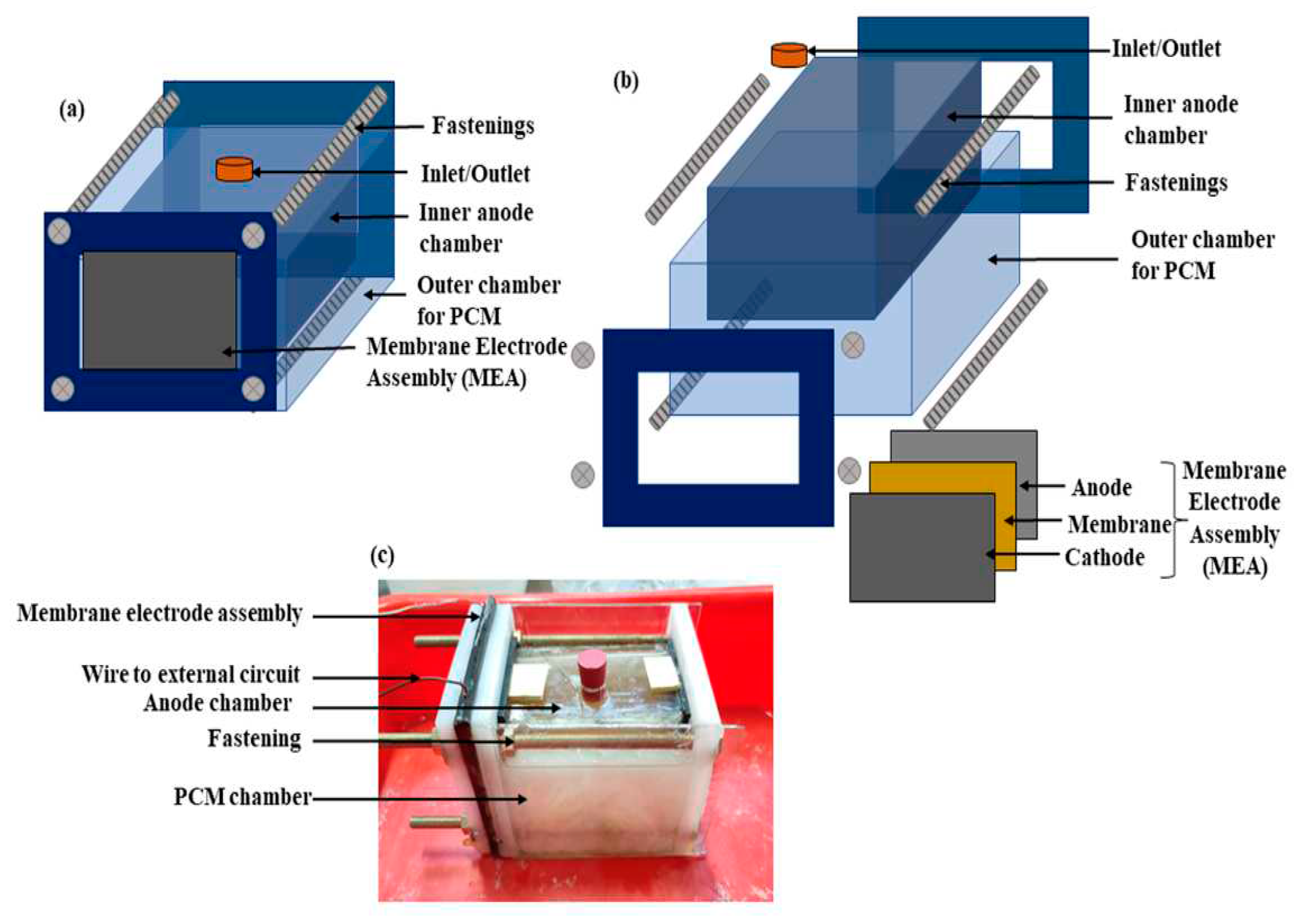
53] on the use of PCMs for thermal management of Microbial Fuel Cel (MFC) opens a new line of research to utilize PCMs in fuel cells for thermal management. This review focuses on MFC technology, but the approach applied in [
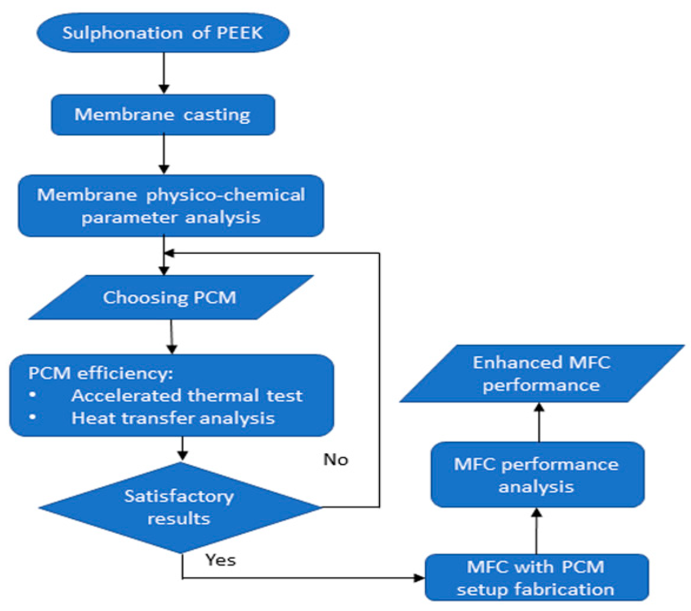
53] can be applied on PEM fuel cells. The authors conducted an experimental study on the use of capric acid to maintain an optimal temperature at the stack.
Figure 7 shows a schematic of the experimental setup. The methodology followed by the authors is presented in
Figure 8.
The PCM can also be used to improve coolant thermal properties. Kazemi-Varnamkhasti et al. [
54] conducted a numerical study on the impact of adding Nano-PCM on the coolant. The coolant is a water. Nano-PCM consists of PCM in the core and a polymer shell. Different PCM fraction were investigated. It was found that adding a 4% of Nano-PCM improved heat storage by 18%.
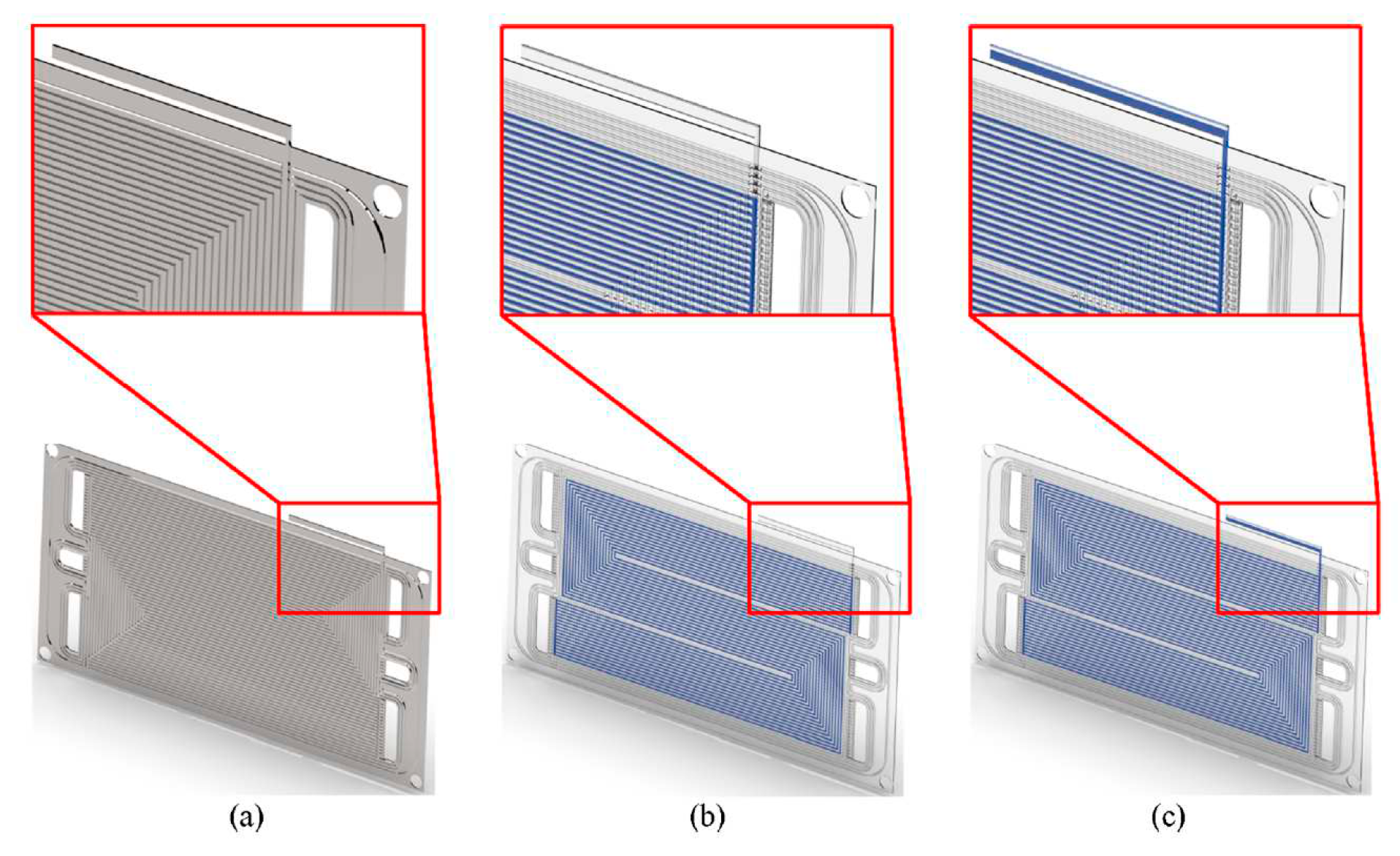
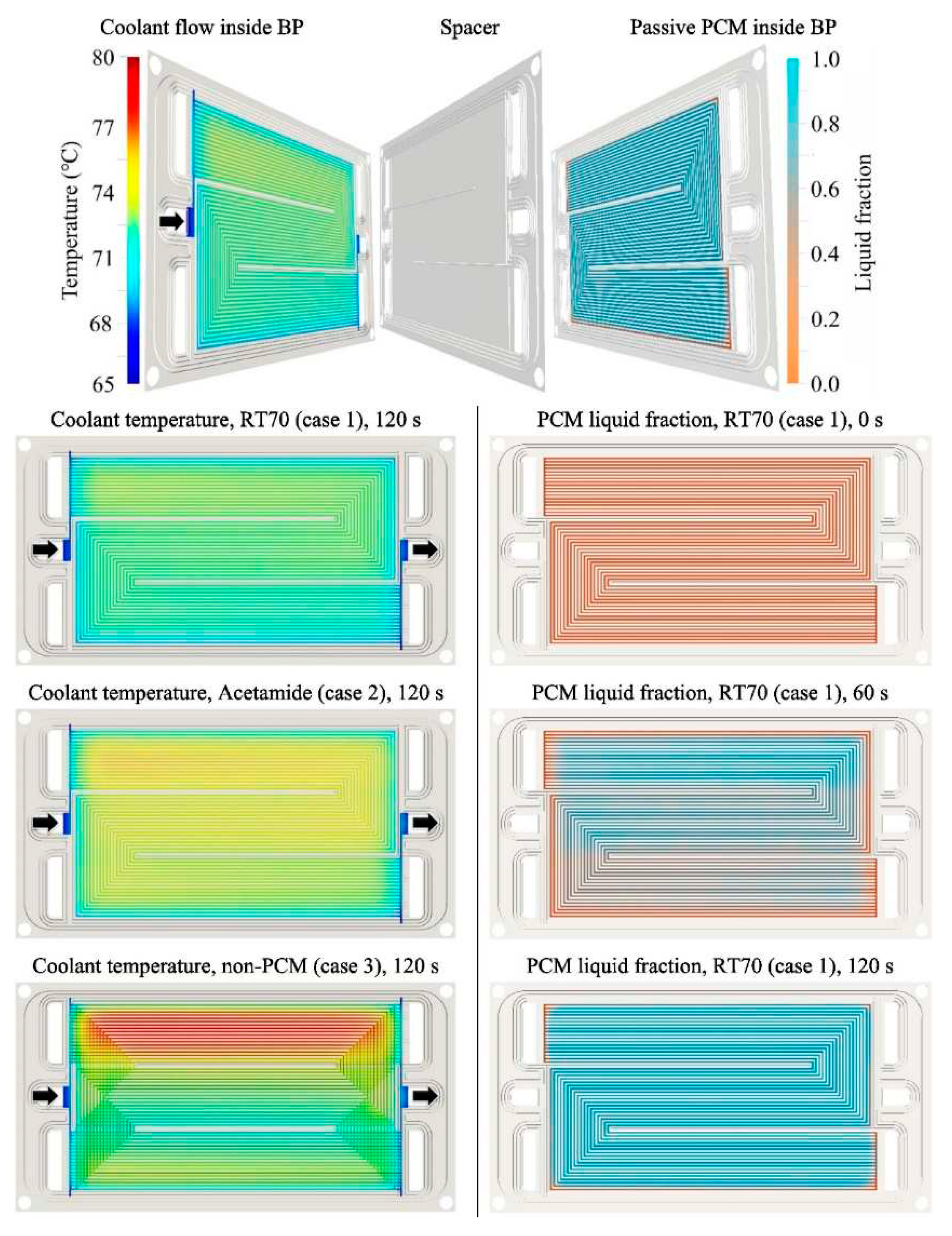
Another possible solution is to integrate PCM into the BPs with a liquid cooling loop. Recently, hybrid solution was studied by Sarani et al. [
55]. The authors investigated the effects of PCMs on the thermal management of a PEMFC are evaluated using a novel 3D model based on an open-source CFD software. The numerical model was validated by comparison with experimental data. PCM has been integrated into BPs as shown in
Figure 9. It was found that the temperature of the model with PCM is uniform, unlike the model without PCM. It was observed that when the cooling system is switched off, the PCM can have a good cooling effect for more than 120s,
Figure 10. It was also found that the PCM can store a significant amount of waste heat.
5. Conclusion
Thermal management of fuel cells is essential for their safety, efficiency and durability. Fuel cell cooling systems can be divided into active and passive cooling systems. This article describes and analyzes cooling systems, a passive cooling heat transfer device used for the thermal management of proton exchange membrane fuel cells. The choice of cooling strategy depends primarily on the fuel cell's ability to generate power. Another important factor in the choice of cooling system is the type of application. Choosing the right cooling system reduces the size and weight of the cell, maintains a constant temperature inside the cell and improves fuel cell performance. Cooling systems are divided into those using phase-change materials and heat pipes. Passive management systems are more suitable for stationary applications with medium power ratings. The main conclusions are listed as below:
For low power ratings (<100 W), the air supplying the cathode can be used to meet cooling requirements.
Heat pipes is an energy-saving cooling solution. It is suitable for medium power and stationary applications. It provides a more uniform temperature distribution than liquid cooling loops.
Heat pipes can present a space problem at the scale of a stack. Micro heat pipes can be a solution in this case.
Recent efforts to improve heat pipe performance have focused on the development of new working fluids and optimized geometry.
PCMs can be used in a number of ways. The first possibility is to integrate pure PCM or composite PCM into the BP or a layer of PCM at stack level.
Nano- PCM can be mixed with coolant to improve cooling loop performance. A rate of 4% has a significant impact on cooling system performance.
Abbreviations
|
Specific heat capacity, (J. kg-1.K-1) |
|
Density, (kg.m-3)
|
| q |
Heat flux |
|
Latent heat of fusion (J.kg-1)
|
|
Time, (s)
|
|
Temperature, (K)
|
|
Thermal conductivity, (W/m.K)
|
References
- AR6 Synthesis Report: Climate Change 2023—IPCC, (n.d.). Available online: https://www.ipcc.ch/report/sixth-assessment-report-cycle/ (accessed on 29 March 29 2023).
- Abdin, Z.; Zafaranloo, A.; Rafiee, A.; Mérida, W.; Lipiński, W.; Khalilpour, K.R. Hydrogen as an energy vector. Renew. Sustain. Energy Rev. 2020, 120, 109620. [Google Scholar] [CrossRef]
- Kovač, A.; Paranos, M.; Marciuš, D. Hydrogen in energy transition: A review. Int. J. Hydrogen Energy 2021, 46, 10016–10035. [Google Scholar] [CrossRef]
- Wang, Y. Modeling of two-phase transport in the diffusion media of polymer electrolyte fuel cells. J. Power Sources 2008, 185, 261–271. [Google Scholar] [CrossRef]
- Chen, Q.; Zhang, G.; Zhang, X.; Sun, C.; Jiao, K.; Wang, Y. Thermal management of polymer electrolyte membrane fuel cells: A review of cooling methods, material properties, and durability. Appl. Energy 2021, 286, 116496. [Google Scholar] [CrossRef]
- Zhao, R.; Zhang, S.; Liu, J.; Gu, J. A review of thermal performance improving methods of lithium ion battery: Electrode modification and thermal management system. J. Power Sources 2015, 299, 557–577. [Google Scholar] [CrossRef]
- Rao, Z.; Wang, S. A review of power battery thermal energy management. Renew. Sustain. Energy Rev. 2011, 15, 4554–4571. [Google Scholar] [CrossRef]
- Ianniciello, L.; Biwolé, P.H.; Achard, P. Electric vehicles batteries thermal management systems employing phase change materials. J. Power Sources 2018, 378, 383–403. [Google Scholar] [CrossRef]
- Khandelwal, M.; Mench, M. Direct measurement of through-plane thermal conductivity and contact resistance in fuel cell materials. J. Power Sources 2006, 161, 1106–1115. [Google Scholar] [CrossRef]
- Shang, K.; Han, C.; Jiang, T.; Chen, Z. Numerical study of PEMFC heat and mass transfer characteristics based on roughness interface thermal resistance model. Int. J. Hydrogen Energy 2023, 48, 7460–7475. [Google Scholar] [CrossRef]
- Turkmen, A.C.; Espinoza-Andaluz, M.; Celik, C.; Sunden, B.; Soyhan, H.S. Impact of the temperature variation on the thermal conductivity of gas diffusion layers for polymer electrolyte fuel cells. Fuel 2023, 345. [Google Scholar] [CrossRef]
- Burheim, O.S.; Su, H.; Pasupathi, S.; Pharoah, J.G.; Pollet, B.G. Thermal conductivity and temperature profiles of the micro porous layers used for the polymer electrolyte membrane fuel cell. Int. J. Hydrogen Energy 2013, 38, 8437–8447. [Google Scholar] [CrossRef]
- PEM Fuel Cells: Thermal and Water Management Fundamentals | Momentum Press. 2013. Available online: https://www.momentumpress.net/node/371 (accessed on 6 April 2023).
- Nóbrega, P.H.A. A review of physics-based low-temperature proton-exchange membrane fuel cell models for system-level water and thermal management studies. J. Power Sources 2023, 558. [Google Scholar] [CrossRef]
- Liu, X.; Bai, M.; Zhou, Z.; Poramapojana, P.; Li, Y.; Gao, L.; Li, Y.; Song, Y. Three-dimensional multi-phase numerical study for the effect of coolant flow field designs on water and thermal management for the large-scale PEMFCs. Int. J. Hydrogen Energy 2023, 48, 23681–23705. [Google Scholar] [CrossRef]
- Wang, M.; Xu, L.; Yang, X. A coupled CFD model for an accurate and fast prediction of the unsteady operation process of a proton exchange membrane fuel cell. Energy Convers. Manag. 2022, 272. [Google Scholar] [CrossRef]
- Futter, G.A.; Gazdzicki, P.; Friedrich, K.A.; Latz, A.; Jahnke, T. Physical modeling of polymer-electrolyte membrane fuel cells: Understanding water management and impedance spectra. J. Power Sources 2018, 391, 148–161. [Google Scholar] [CrossRef]
- Chaudhary, S.; Sachan, V.K.; Bhattacharya, P.K. Two dimensional modelling of water uptake in proton exchange membrane fuel cell. Int. J. Hydrogen Energy 2014, 39, 17802–17818. [Google Scholar] [CrossRef]
- Gerteisen, D.; Heilmann, T.; Ziegler, C. Modeling the phenomena of dehydration and flooding of a polymer electrolyte membrane fuel cell. J. Power Sources 2009, 187, 165–181. [Google Scholar] [CrossRef]
- Jiao, K.; Li, X. Three-dimensional multiphase modeling of cold start processes in polymer electrolyte membrane fuel cells. Electrochimica Acta 2009, 54, 6876–6891. [Google Scholar] [CrossRef]
- Han, J.; Han, J.; Hwang, J.; Hwang, J.; Yu, S.; Yu, S. A simulation of automotive fuel cell system for oxygen starvation trends by compressor surge under load follow-up. Appl. Therm. Eng. 2019, 154, 251–262. [Google Scholar] [CrossRef]
- Vetter, R.; Schumacher, J.O. Free open reference implementation of a two-phase PEM fuel cell model. Comput. Phys. Commun. 2018, 234, 223–234. [Google Scholar] [CrossRef]
- Springer, T.E.; Zawodzinski, T.A.; Gottesfeld, S. Polymer Electrolyte Fuel Cell Model. J. Electrochem. Soc. 1991, 138, 2334–2342. [Google Scholar] [CrossRef]
- Schröder, M.; Becker, F.; Kallo, J.; Gentner, C. Optimal operating conditions of PEM fuel cells in commercial aircraft. Int. J. Hydrogen Energy 2021, 46, 33218–33240. [Google Scholar] [CrossRef]
- Pourrahmani, H.; Yavarinasab, A.; Siavashi, M.; Matian, M.; Van Herle, J. Progress in the proton exchange membrane fuel cells (PEMFCs) water/thermal management: From theory to the current challenges and real-time fault diagnosis methods. Energy Rev. 2022, 1. [Google Scholar] [CrossRef]
- Xing, S.; Zhao, C.; Zou, J.; Zaman, S.; Yu, Y.; Gong, H.; Wang, Y.; Chen, M.; Wang, M.; Lin, M.; et al. Recent advances in heat and water management of forced-convection open-cathode proton exchange membrane fuel cells. Renew. Sustain. Energy Rev. 2022, 165. [Google Scholar] [CrossRef]
- Wang, J.; Wang, H.; Fan, Y. Techno-Economic Challenges of Fuel Cell Commercialization. Engineering 2018, 4, 352–360. [Google Scholar] [CrossRef]
- Xu, J.; Zhang, C.; Wan, Z.; Chen, X.; Chan, S.H.; Tu, Z. Progress and perspectives of integrated thermal management systems in PEM fuel cell vehicles: A review. Renew. Sustain. Energy Rev. 2021, 155, 111908. [Google Scholar] [CrossRef]
- Zhang, G.; Kandlikar, S.G. A critical review of cooling techniques in proton exchange membrane fuel cell stacks. Int. J. Hydrogen Energy 2012, 37, 2412–2429. [Google Scholar] [CrossRef]
- Wang, Y.; Diaz, D.F.R.; Chen, K.S.; Wang, Z.; Adroher, X.C. Materials, technological status, and fundamentals of PEM fuel cells—A review. Mater. Today 2020, 32, 178–203. [Google Scholar] [CrossRef]
- Fuel Cell Systems Explained, 2nd Edition | Wiley, Wiley.Com. (n.d.). Available online: https://www.wiley.com/en-ie/Fuel+Cell+Systems+Explained%2C+2nd+Edition-p-9781118878330 (accessed on 5 May 2023).
- Islam, M.; Shabani, B.; Rosengarten, G.; Andrews, J. The potential of using nanofluids in PEM fuel cell cooling systems: A review. Renew. Sustain. Energy Rev. 2015, 48, 523–539. [Google Scholar] [CrossRef]
- Hosseinzadeh, E.; Rokni, M.; Rabbani, A.; Mortensen, H.H. Thermal and water management of low temperature Proton Exchange Membrane Fuel Cell in fork-lift truck power system. Appl. Energy 2013, 104, 434–444. [Google Scholar] [CrossRef]
- Choi, J.; Kim, Y.-H.; Lee, Y.; Lee, K.-J.; Kim, Y. Numerical analysis on the performance of cooling plates in a PEFC. J. Mech. Sci. Technol. 2008, 22, 1417–1425. [Google Scholar] [CrossRef]
- Baek, S.M.; Yu, S.H.; Nam, J.H.; Kim, C.-J. A numerical study on uniform cooling of large-scale PEMFCs with different coolant flow field designs. Appl. Therm. Eng. 2011, 31, 1427–1434. [Google Scholar] [CrossRef]
- Sasmito, A.P.; Birgersson, E.; Mujumdar, A.S. Numerical Investigation of Liquid Water Cooling for a Proton Exchange Membrane Fuel Cell Stack. Heat Transf. Eng. 2011, 32, 151–167. [Google Scholar] [CrossRef]
- Weiss-Ungethüm, J.; Bürger, I.; Schmidt, N.; Linder, M.; Kallo, J. Experimental investigation of a liquid cooled high temperature proton exchange membrane (HT-PEM) fuel cell coupled to a sodium alanate tank. Int. J. Hydrogen Energy 2014, 39, 5931–5941. [Google Scholar] [CrossRef]
- Chan, C.; Siqueiros, E.; Ling-Chin, J.; Royapoor, M.; Roskilly, A. Heat utilisation technologies: A critical review of heat pipes. Renew. Sustain. Energy Rev. 2015, 50, 615–627. [Google Scholar] [CrossRef]
- Heat pipes for PEM fuel cell cooling: State of the art review. Mater. Today Proc. 2023. [CrossRef]
- Wang, L.; Quan, Z.; Zhao, Y.; Yang, M.; Jing, H. Heat transfer process analysis and performance research of micro heat pipe array applied for the thermal management of proton exchange membrane fuel cells. Appl. Therm. Eng. 2023, 219. [Google Scholar] [CrossRef]
- Yang, M.; Quan, Z.; Zhao, Y.; Wang, L.; Liu, Z.; Tang, S. Experimental and numerical study on thermal management of air-cooled proton exchange membrane fuel cell stack with micro heat pipe arrays. Energy Convers. Manag. 2023, 275. [Google Scholar] [CrossRef]
- Han, Y.; Zhuge, W.; Peng, J.; Qian, Y.; Ming, P.; Zhang, Y. A novel heat pipe bipolar plate for proton exchange membrane fuel cells. Energy Convers. Manag. 2023, 284. [Google Scholar] [CrossRef]
- Min, C.; Gao, X.; Li, F.; Wang, K. Thermal performance analyses of pulsating heat pipe for application in proton exchange member fuel cell. Energy Convers. Manag. 2022, 259, 115566. [Google Scholar] [CrossRef]
- Huang, B.; Jian, Q.; Luo, L.; Bai, X. Research on the in-plane temperature distribution in a PEMFC stack integrated with flat-plate heat pipe under different startup strategies and inclination angles. Appl. Therm. Eng. 2020, 179, 115741. [Google Scholar] [CrossRef]
- Clement, J.; Wang, X. Experimental investigation of pulsating heat pipe performance with regard to fuel cell cooling application. Appl. Therm. Eng. 2012, 50, 268–274. [Google Scholar] [CrossRef]
- Huang, Z.; Jian, Q.; Luo, L.; Huang, B.; Bai, X.; Li, D. Rapid thermal response and sensitivity analysis of proton exchange membrane fuel cell stack with ultra-thin vapor chambers. Appl. Therm. Eng. 2021, 199, 117526. [Google Scholar] [CrossRef]
- El Idi, M.M.; Karkri, M.; Tankari, M.A. A passive thermal management system of Li-ion batteries using PCM composites: Experimental and numerical investigations. Int. J. Heat Mass Transf. 2021, 169, 120894. [Google Scholar] [CrossRef]
- EL Idi, M.M.; Karkri, M.; Tankari, M.A.; Vincent, S. Hybrid cooling based battery thermal management using composite phase change materials and forced convection. J. Energy Storage 2021, 41. [Google Scholar] [CrossRef]
- Zalba, B.; Marı́n, J.M.; Cabeza, L.F.; Mehling, H. Review on thermal energy storage with phase change: materials, heat transfer analysis and applications. Appl. Therm. Eng. 2003, 23, 251–283. [Google Scholar] [CrossRef]
- Boussaba, L.; Makhlouf, S.; Foufa, A.; Lefebvre, G.; Royon, L. vegetable fat: A low-cost bio-based phase change material for thermal energy storage in buildings. J. Build. Eng. 2018, 21, 222–229. [Google Scholar] [CrossRef]
- Boussaba, L.; Foufa, A.; Makhlouf, S.; Lefebvre, G.; Royon, L. Elaboration and properties of a composite bio-based PCM for an application in building envelopes. Constr. Build. Mater. 2018, 185, 156–165. [Google Scholar] [CrossRef]
- Sasmito, A.P.; Shamim, T.; Mujumdar, A.S. Passive thermal management for PEM fuel cell stack under cold weather condition using phase change materials (PCM). Appl. Therm. Eng. 2013, 58, 615–625. [Google Scholar] [CrossRef]
- Solomon, J.; Kugarajah, V.; Ganesan, P.; Dharmalingam, S. Enhancing power generation by maintaining operating temperature using Phase Change Material for Microbial Fuel Cell application. J. Environ. Chem. Eng. 2022, 10. [Google Scholar] [CrossRef]
- Kazemi-Varnamkhasti, H.; Khazaee, I.; Ameri, M.; Toghraie, D. Heat storage and increasing the rate of heat transfer in polymer electrolyte membrane fuel cell by adding nano-encapsulated phase change material to water in the cooling process. J. Energy Storage 2023, 59. [Google Scholar] [CrossRef]
- Sarani, I.; Xie, B.; Bao, Z.; Huo, W.; Li, X.; Xu, Y.; Wang, B.; Jiao, K. Analysis of phase change material thermal effects in large-scale proton-exchange membrane fuel cell based on open-source computational fluid dynamics. Appl. Therm. Eng. 2022, 216. [Google Scholar] [CrossRef]
|
Disclaimer/Publisher’s Note: The statements, opinions and data contained in all publications are solely those of the individual author(s) and contributor(s) and not of MDPI and/or the editor(s). MDPI and/or the editor(s) disclaim responsibility for any injury to people or property resulting from any ideas, methods, instructions or products referred to in the content. |
© 2023 by the authors. Licensee MDPI, Basel, Switzerland. This article is an open access article distributed under the terms and conditions of the Creative Commons Attribution (CC BY) license (http://creativecommons.org/licenses/by/4.0/).
