1. Introduction
Compared with other terrestrial communications, the underground environment in mines is harsh. Rough walls, dust, and obstacles cause severe signal fading, thus increasing the BER(Bit Error Rate)[
1]. In recent years, the proposed deep receiver with DNN (Deep Neutral Network) instead of the receiver side as a whole requires a large amount of data and takes a long training time to achieve good detection results[
2].
The literature [
2] uses DenseNet to replace the receiver side, and the deep receiver applies deep learning algorithms to the receiver side, solves the error accumulation problem of conventional receivers, does not rely on theoretical modeling of traditional communication knowledge, and achieves optimal overall performance at the receiver side. The literature [
3] implements a smart receiver by optimizing the structure of Densenet neural network, and this method can avoid the complex pilot operation and signal error accumulation problem also improves the reception performance of OFDM communication system. The literature [
4] proposes Deep Complex-valued Convolutional Networks (DCCN) receiver that replaces detection and demodulation in the receiver with CNN(Convolutional Neural Networks) in wireless environments, which outperforms Rayleigh fading channels with different delay and mobility Based on conventional channel estimators with ideal and approximate LMMSE (Linear Minimum Mean Square Error) estimation and conventional CP(Cyclic Prefix) enhancement techniques, the DCCN receiver can improve the signal fading of conventional receivers in Rayleigh channels. The deep receivers in the above literature suffer from the problems of not being supported by theoretical knowledge, requiring large amounts of data and taking a long training time.
To address the above issues, a model-driven idea is used to combine deep learning with traditional communication knowledge at the receiver side, by further reducing the complexity and training time of the network. In the literature[
5] in OFDM(Orthogonal frequency-division multiplexing) system channel estimation and signal detection DNN (Deep Neutral Network) network model consists of five fully connected layers and the middle three layers are hidden layers. The number of neurons per layer was 256, 500, 250, 120, and 16, respectively. The deep learning method has advantages when the wireless channel has severe distortion and interference. However, it also has the problem of simple network structure and relatively large number of trainable parameters. A joint channel estimation and signal detection method based on deep learning in OFDM systems is proposed in the literature [
6]. Compared with traditional channel estimation and signal detection methods, CENet (channel estimation network ) and CCRNet (Channel Conditional Recovery Network) have better performance. However, the structure of the CCRNet network in the literature [
6] is more complex and CENet is based on the use of image super-resolution techniques[
7] and in the literature[
8] also treats the channel as an image and it modifies the denoising network proposed in [
9] to perform channel estimation. However, in the case of fast fading, the pilots overhead is large and the neural network structure is not optimized for the channel estimation problem, so further improvements in computational complexity and estimation error performance are needed. A channel estimation network based on ReEsNet (Residual channel Estimation Network) specifically designed for channel estimation is introduced in the literature[
10]. It outperforms other deep learning-based estimation methods and can be comparable to the MMSE (Minimum Mean Square Error) estimation performance. However, there are some problems that have not been applied for channel estimation in complex channels like mines.
Therefore, in this paper, a network based on the combination of ReEsNet and SDRNet (Signal Detection Recovery Network ) is proposed for channel estimation and signal detection in underground mines in order to maintain the accuracy of channel estimation and signal detection even with low complexity of the network structure and few training parameters. Experimental results demonstrate that the combined ReEsNet and SDRNet have good detection performance compared to the conventional channel estimation and signal detection in complex mine environments. Compared with the proposed joint channel estimation and signal detection methods, the network is less complex, can be trained with fewer parameters and can also achieve signal detection with little difference. The main contributions of this paper are as follows:
For the first time, ReESNet is applied to interpolation of channel estimation in a complex environment in a mine. Compare the interpolation results of channel estimation for 64 and 128 subcarrier cases. Demonstrate the superiority of ReESNet interpolation in channel estimation;
For the problem of low BER of signal detection in underground mines, SDRNet is proposed for signal detection, and compared with traditional detection methods for comparison, SDRNet for signal detection achieves good detection results;
For the problem of large amount of training data and long training time of deep receivers, the channel estimation and signal detection method based on joint ReESNet and SDRNet under mine is proposed by combining communication knowledge with deep neural network at the receiver side;
Comparing the joint ReEsNet and SDRNet channel estimation and signal detection with the literature5 and literature6, ReEsNet also has better channel estimation interpolation compared to the conventional channel estimation interpolation. The detection results with few trainable parameters can also be achieved with little difference from other networks for signal detection.
2. Materials and Methods
2.1. Mine wireless channel model
The main focus of the mine wireless communication system is the simulation of the mine wireless channel, other modules modulation, join the protection interval and join the pilots, etc. are consistent with the general communication system method will not be described in detail. The mine wireless channel is complex and there are many factors as possible in the mine environment when establishing the mine wireless channel.
Since coal production is mainly produced underground, in a harsh environment and with many unsafe factors, it is important to consider the influence of various factors in the underground coal mines as much as possible, so as to establish a mine wireless channel. Most of the mines in our country are flat tunnels, and electromagnetic wave transmission in such channels mainly contains two kinds of fading: large-scale fading and small-scale fading. Large-scale fading is mainly the signal fading caused by long distance and long time; small-scale fading is mainly caused by multipath propagation.
Firstly, the statistical properties of small-scale fading are analyzed, assuming that the signal entering the channel is equation 1, in which s1(t) is equivalent to the amplitude of the low-pass signal and f1 is the carrier frequency. Thus, the discrete multipath signals can be expressed as equation 2.
where an represents the fading magnitude of the nth path, τn(t) represents the time delay of the n-th path, and L is the number of paths.<!-- MathType@Translator@5@5@MathML2 (no namespace).tdl@MathML 2.0
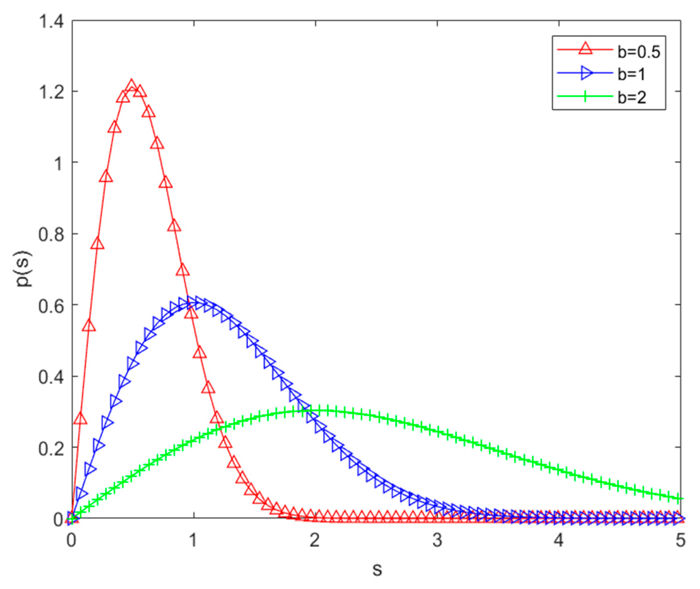
Small-scale fading is mainly an instantaneous and intense change in received power. In multipath propagation, the multipath signals received at the receiver without line-of-sight propagation can be described in terms of Rayleigh channels. The probability density function of the Rayleigh distribution is shown in (3):
where s represents the received signals amplitude value, σ
2 is the mean energy value of the received signals, and
Figure 1 shows the probability density function of the Rayleigh distribution.
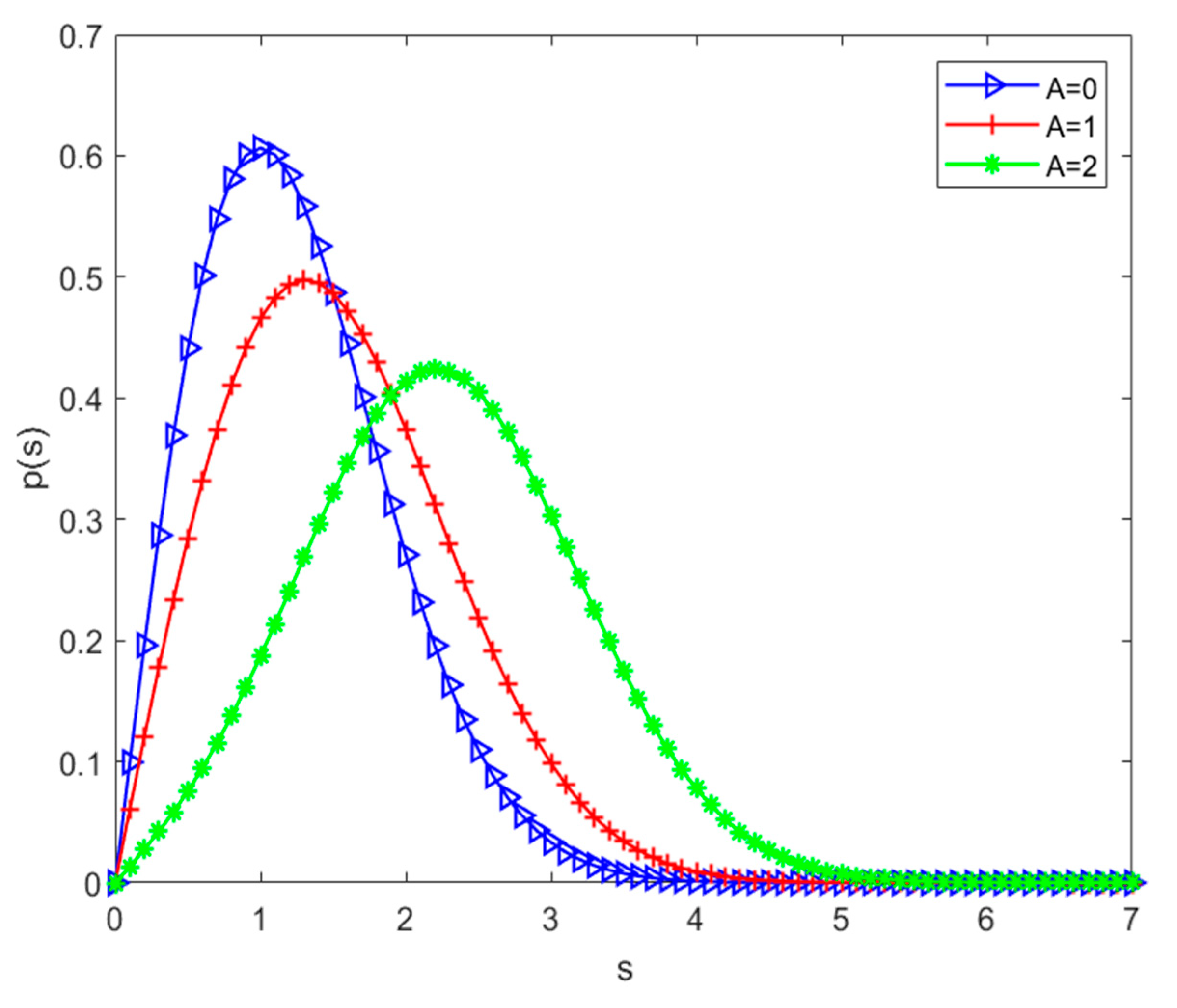
When there is line-of-sight propagation between the transmitter and the receiver, and the strength of the signal of one main path is greater than that of the other paths, the received signal envelope obeys the Rice distribution. Equation (4) is the probability density function of the Rice distribution.
A is the peak of the line-of-sight path, and the probability density function of the Rice distribution is shown in
Figure 2. The Rice distribution can be described by A/2σ
2, and when this value tends to zero, it can be approximated as a Rayleigh distribution.
Both distributions are relatively classical, but they also do not accurately characterize the complex environmental signals. Next we analyze the characteristics of the underground channel in the mine.
Since underground tunnels are generally unlikely to be empty tunnels, signal transmission in such tunnels generally does not have line-of-sight propagation either, so the signal transmission envelope mostly belongs to Rayleigh distribution. The maximum Doppler shift is . The locomotive moves at 30km/h down the mine with a carrier wave of 3.5GHz.
Using Jakes power spectrue . According to the above analysis taking the sampling interval as 50ns and 9 taps, the delayed tap model can be calculated for 8 paths.
Table 1.
Multipath parameters of the mine channel.
Table 1.
Multipath parameters of the mine channel.
| Trail Number |
Multipath delay/ns |
Power / dbm |
| 1 |
0 |
0.0 |
| 2 |
50 |
-2.4 |
| 3 |
100 |
-4.8 |
| 4 |
150 |
-7.2 |
| 5 |
200 |
-9.6 |
| 6 |
250 |
-12.0 |
| 7 |
300 |
-14.4 |
| 8 |
350 |
-16.8 |
The parameters in the above table are basically consistent with the actual measured values in the tunnel, so they are used as the model simulation parameters for small-scale fading under the mine.
Large-scale fading in mines is mainly caused by the radio signals at the transmitter and receiver ends being blocked by the mining equipment and roadway rock formations during propagation. Large-scale fading is a relatively drastic change in the instantaneous power of the received signal. In general, large scale fading can be described in terms of average path loss and shadow scale fading. The average path loss is only related to the transmission path, and the longer the path, the higher its loss. In underground mines there are more obstacles, and the signal is more susceptible to this, thus causing attenuation [
11]. The shadow fading obeys the normal distribution of random variables and its probability density function is shown in (5):
where: z is the ratio of transmitted power to received power; u is the mean of lnz is the mean value of lnz; σ is the standard deviation of lnz.
2.2. Detection model based on combined ReEsNet and SDRNet in underground mines
In this paper the block diagram of OFDM mine wireless communication system is shown in
Figure 3. The transmitter side is consistent with the conventional OFDM system and will not be described too much. The main focus is to establish mine wireless channels and combine deep neural networks with traditional knowledge of wireless communication at the receiver side to make the framework more interpretable and also reduce the training time. ReEsNet is used to replace the interpolation of traditional channel estimation, and after ReEsNet interpolation, the interpolated data is channel equalized and the pilots are removed then the data is fed into SDRNet for training. SDRNet replaces the traditional signal demodulation to recover the received signal.
In order to estimate the channel impulse response, a pilot at known positions are usually added [
12]. According to the channel impulse response of the pilot, the response matrix of the whole channel can be obtained by linear interpolation or Gauss interpolation[
13]. The conventional channel estimation methods are LS (Least Square), MMSE. The channel impulse response of LS at pilot can be expressed as [
14], and the estimate of MMSE is [
15]. Where YP represents the signal received at the pilot and Xp represents the transmitted signal at the known pilots location. Equation (6) RH denotes the matrix of channel correlation at the pilot. LS estimation is strongly affected by noise, so the performance is less satisfactory at low SNR(Signal to Noise Ratio). In contrast, MMSE estimation requires the calculation of the two-order matrix as well as the true channel matrix of the channel, which is more complex and difficult to implement. These two traditional methods are more dependent on the pilots, and the resources of the spectrum are very precious, so DNNs have been proposed for channel estimation, which can achieve good results by using a small amount of the pilots for the whole channel estimation. Therefore, in this paper, ReEsNet is used for interpolation of channel estimation so that it can achieve slightly higher accuracy than that of MMSE channel estimation. The mean square error is also used as the loss function. The loss function of channel estimation is shown in (7), which represents the estimated signal impulse response.
is expressed as the estimated signal impulse response, and H
i represents the frequency-domain impulse response of a real channel.
Traditional signal detection methods include zero-forcing and LMMSE (Linear Minimum Mean Square Error) . Zero-forcing detection algorithm formula as shown in (8),
represents the state of the entire channel information. The LMMSE algorithm is shown in Equation 10, in which
represents the conjugate transpose matrix of the channel state information, I is the unit matrix, and SNR is the Signal to Noise Ratio. Deep neural network is used in signal detection and has been proved to have good detection performance. Therefore, in this paper, SDRNet is used instead of the traditional signal demodulation to achieve signal recovery.
The overall model of the joint down-mine based channel estimation and signal detection network proposed in this paper is presented above, and the components of each part of the network and its principles are described in detail below.
2.3. A Network model based on ReEsNet channel estimation
Since the emergence of deep residuals network, they have been widely used in various aspects. Instead of learning a direct mapping of inputs to outputs, it learns a mapping of inputs to residuals[
16]. It has two main advantages. First, it makes the training network easier to train by learning the mapping of input and residuals, learning more significant differences, thus improving the efficiency. Secondly, it alleviates the problem of gradient disappearance in deep learning networks[
17].
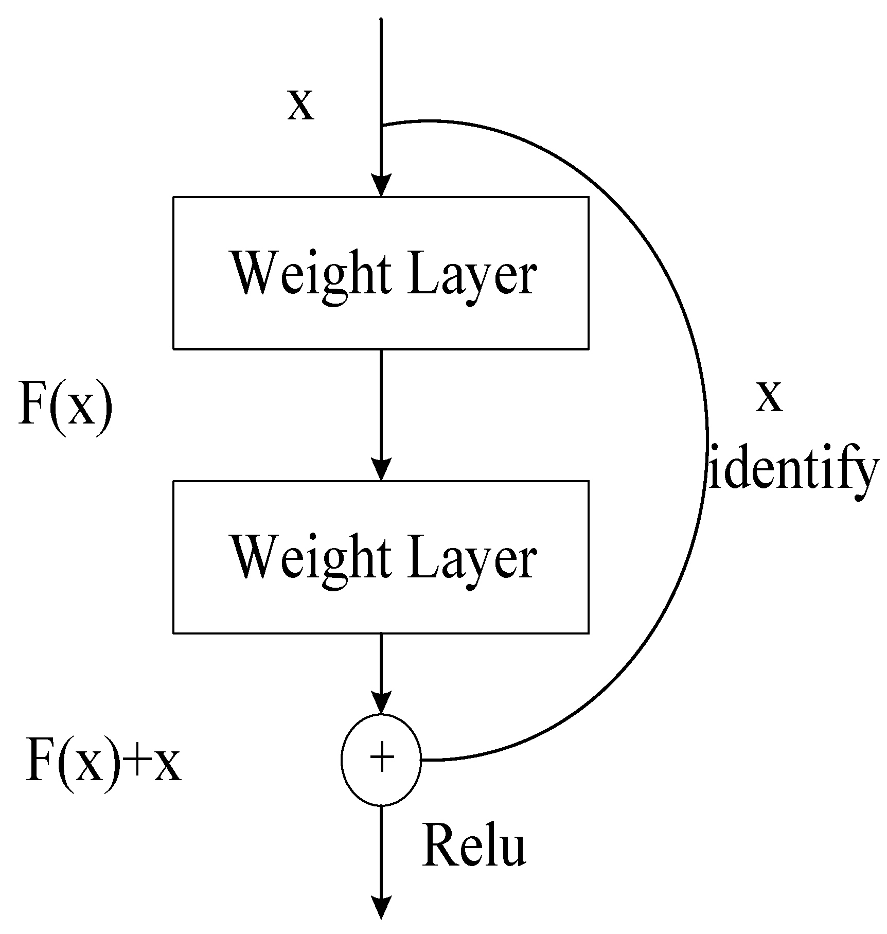
The deep residual function is shown in
Figure 4. Assuming that the optimal function is denoted as H(x) within a certain layer, then the objective function F(x) = H(x) - x that we fit is called the "residual function". The constant function part of the residual block, also known as the skip link . Corresponding to the neural network, the mathematical expression of the residual block is shown in (11).
where y represents the output of the residual block, σ (·) represents the activation function, F (·) represents the residual function, x represents the input, and W represents the ownership weight of the residual block.
We use ReEsNet, a neural network based on residual learning specifically designed for the channel, and ReEsNet is based on an improvement of the super-resolution model proposed in [
18] . The network structure of ReEsNet is shown in
Figure 5. The first layer is a convolutional layer , and then followed by four ResBlocks, which are different from the classical ResBlocks in that there is no BatchNormalization and Activation. The latter is followed by a convolutional layer, a short connection, an upsampling layer, a convolutional layer, a convolutional layer, a ReLU activation function, a convolutional layer, and a short connection. This is the network structure of ReEsNet.
The pilot in the channel estimation are passed through the ReEsNet network structure, and then the interpolation results of the channel estimation are output. The mean square error loss function of the interpolation result and the CSI (Channel State Information) of the original channel is used as the evaluation metric for the channel estimation of the ReEsNet network. Among them, the nodes of the ReEsNet network structure are shown in
Table 2.
2.4. Network model based on SDRNet signal detection
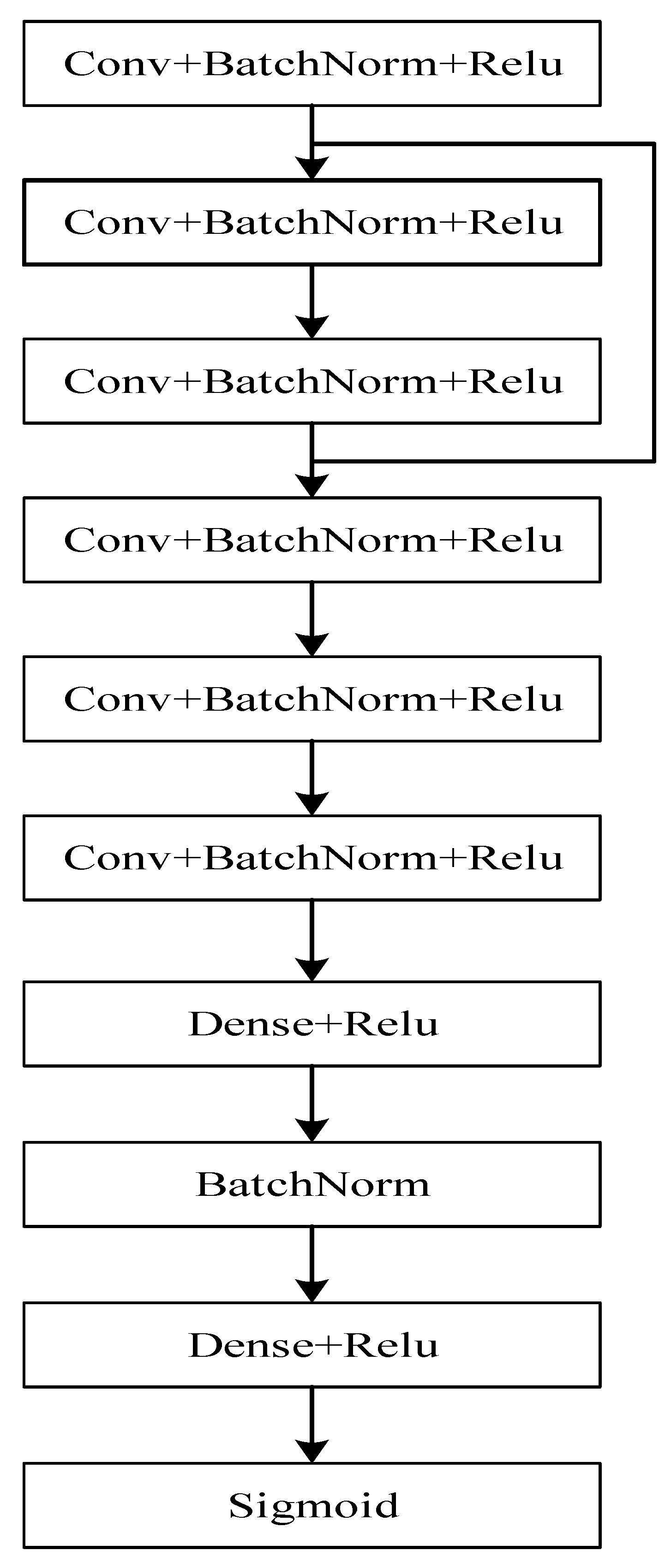
Signal detection is mainly the part of modulation of the received signal. Based on the signal detection networks proposed in literature 5 and literature 6, this paper improves on these two networks, thus proposing SDRNet to recover the signal. SDRNet has a lower network complexity and fewer parameters to train, and can maintain good detection performance in this case as well. SDRNet uses the network structure of conditional encoding from the literature 5. The fully connected layers of the literature 6 are then used, but only two of them, and then the parameters are adjusted so that the number of neurons and the number of convolutional kernels can maintain good detection performance even with a smaller number of neurons. The network architecture of SDRNet is shown in
Figure 6:
SDRNet consists of six convolutional layers, regularization and Relu activation functions, and two fully connected layers. The parameters of the convolutional layers and fully connected layers are shown in
Table 3:
3. Experiments
In this paper, Matlab and Python are applied for experimental simulation. OFDM pilot impulse response samples and the corresponding real channel state information as labels are generated by Matlab2022a. Both networks, ReEsNet and SDRNet, are built from various libraries in Tensorflow. The produced dataset consists of the channel state information at the pilots as input, the real whole channel state information as label, and the mean square error as loss function. After the data predicted by ReEsNet, the channel is equalized and the pilot is removed as the input of SDRNet, and the bit stream at the transmitter is used as the label. Since this is a detection problem of regression, the mean square error is also used as a loss function, and the accuracy is used as a judgment of the training output. In total, there are 24,000 training samples, 6,000 validation samples and 3,000 test samples (The SNR range is 1-30) . The simulation parameters in this paper are set as shown in
Table 4. The modulation mode is QPSK and the FFT point number is 128. The channel multipath delay is [0,50,100,150,200,250,300,350]*1e-9, but in the simulation the channel relative delay is the multipath delay divided by the sampling interval.
DNN mainly learns data features from training data and achieves good results on the training set to extend to more data sets, so it is important to build sample data. Since DNN training networks generally cannot be trained directly on complex numbers, the complex numbers of each sample are extracted to make a real part and an imaginary part of the dataset.
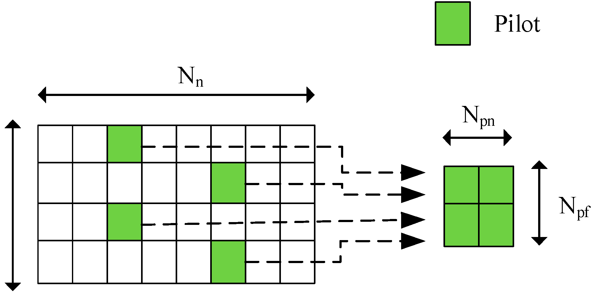
Usually pilots are sparsely and evenly placed in the time-frequency grids for channel estimation purpose. In frequency domain the received symbols at pilots positions Y
p ∈ C N
pf ×N
pn can be written as
where X
p∈CN
pf×N
pn are pilots symbols. As illustrated in
Figure 7, Npf is the number of pilot symbols placed along subcarriers axis, Npn is the number of pilot symbols placed along OFDM symbols axis. Hp∈C
Npf×Npn are channel coefficients at pilots positions. W
p are AWGN at pilot positions.
The goal is to estimate H based on Yp and Xp. We introduce two conventional estimation methods here, least square (LS) estimation and linear minimum mean square error (LMMSE) estimation.
The training dataset is constructed as shown in
Figure 7, The generated training samples are generated in cycles with each different SNR, so it is necessary to shuffle the order of the data.
The distortion or damage of the channel is too severe to allow normal communication. So, when the signal is distorted or corrupted by the wireless channel, how do you ensure that the transmitted signal (data) is properly received (decoded) by the receiver? One of the most common solutions is to use a special component called an equalizer. Therefore, the output sample data is equalized in the ReEsNet network, and the equation for equalization is shown below, where x is the transmit signal and y is the receive signal.
After performing equalization then start removing the pilot. Removing the pilots are to remove the data from the sample at the location where the pilots are located, keeping only the data part. After processing each sample data, the processed sample data is D2.
In summary, the training and inference algorithms based on the joint ReEsNet and SDRNet are shown in
Table 5 as presented. In this paper, the network is trained with Tensorflow-GPU in Python, and the parameters set for the training network are shown in
Table 5, and the most appropriate parameter settings are selected after extensive training.
4. Results and Discussion
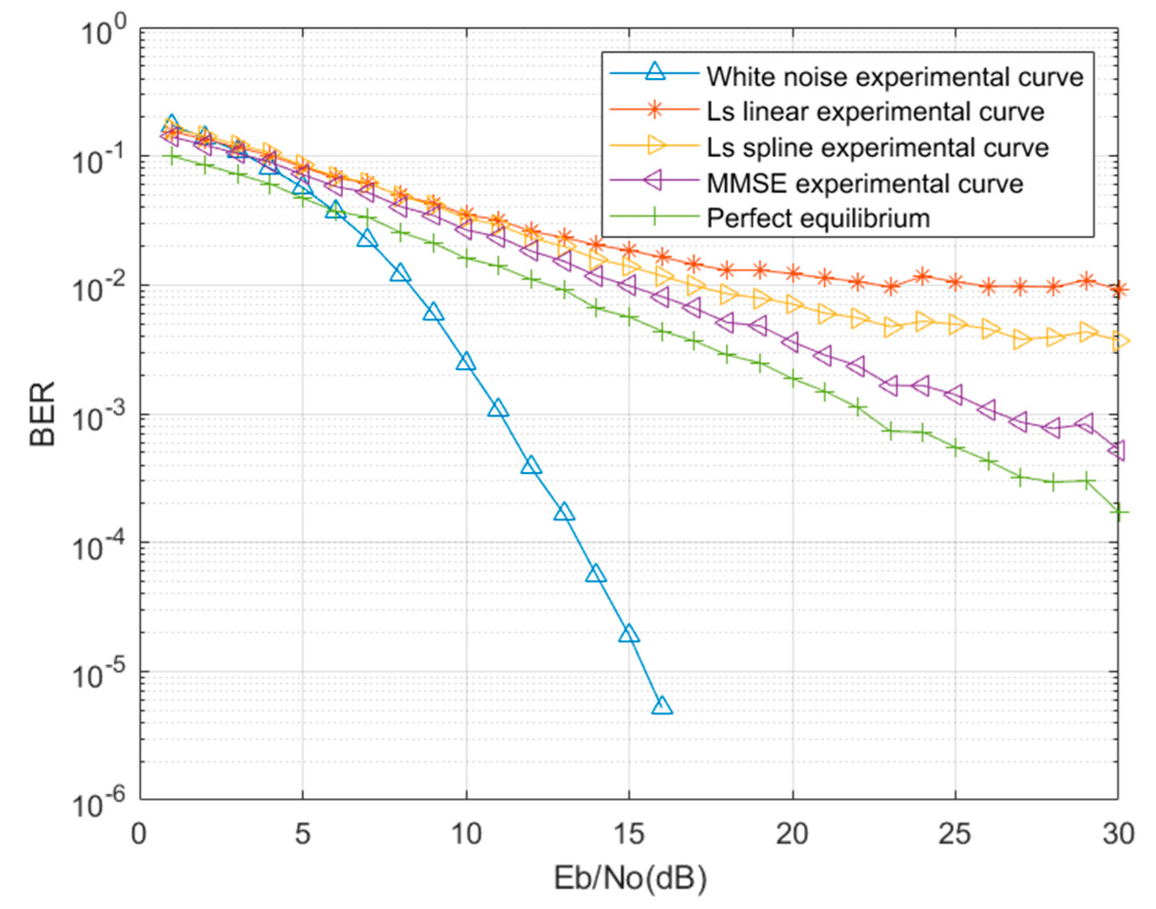
In this paper, mine wireless channel is established according to the characteristics of mine channel, then LS estimation, MMSE channel estimation and perfect equalization of known channel are performed. The perfect equalization is that the receiver knows the real channel matrix H and performs the equalization directly with FFT(Fast Fourier Transform).
Figure 8 is the result of signal detection simulation in mine. The error rate curve when the number of FFT points is 128. When the FFT points are set to 128, only the white noise has the lowest bit error rate, and the perfect equalization has the best performance in the mine channel, followed by MMSE estimation, LS is estimated by two traditional interpolation methods: linear interpolation and spline interpolation. The performance of spline interpolation is better than that of linear interpolation. It can be seen in
Figure 8 that the BER(Bit Error Rate) performance is not very good at low SNR, and according to previous studies the DNN used at the OFDM receiver has been shown to achieve good performance. Therefore, we use DNN to replace the channel estimation and signal detection at the OFDM receiver.
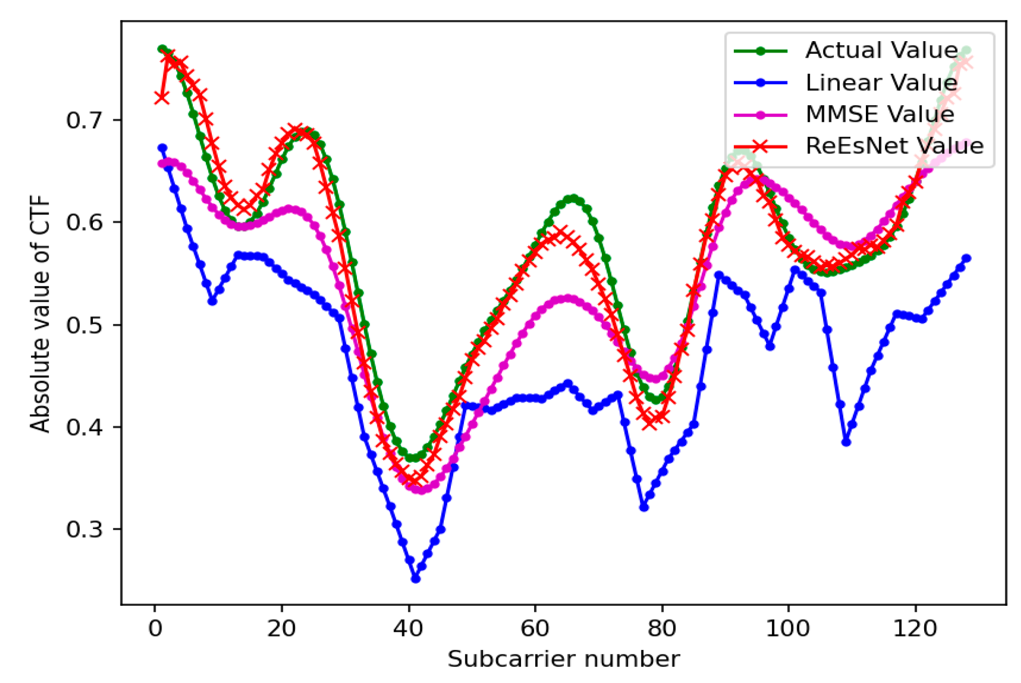
Figure 9 shows the comparison of the real part amplitude value parameters in 128 subcarrier channel estimation under the mine. In this paper, the perfectly balanced channel state information is used as the label of the output network of ReEsNet. The effect of the network test set in ReEsNet is shown in Fig 6, which shows the comparison of the magnitude value of the real part of the subcarrier when the number of subcarriers is 128. The horizontal coordinate is the number of subcarriers and the vertical coordinate is the amplitude value, Firure 9 mainly shows the value of the real part. It is obvious in the figure that the interpolation of the ReEsNet channel estimation is the closest to the state information of the real channel, the MMSE is the next closest, and the linear interpolation of the LS estimation is the worst. To demonstrate the excellent performance in interpolation of ReEsNet channel estimation, the following experiments save the parameters after training the network in 128 subcarriers, and then load the parameters of the model to test the effect of 64 subcarriers directly.
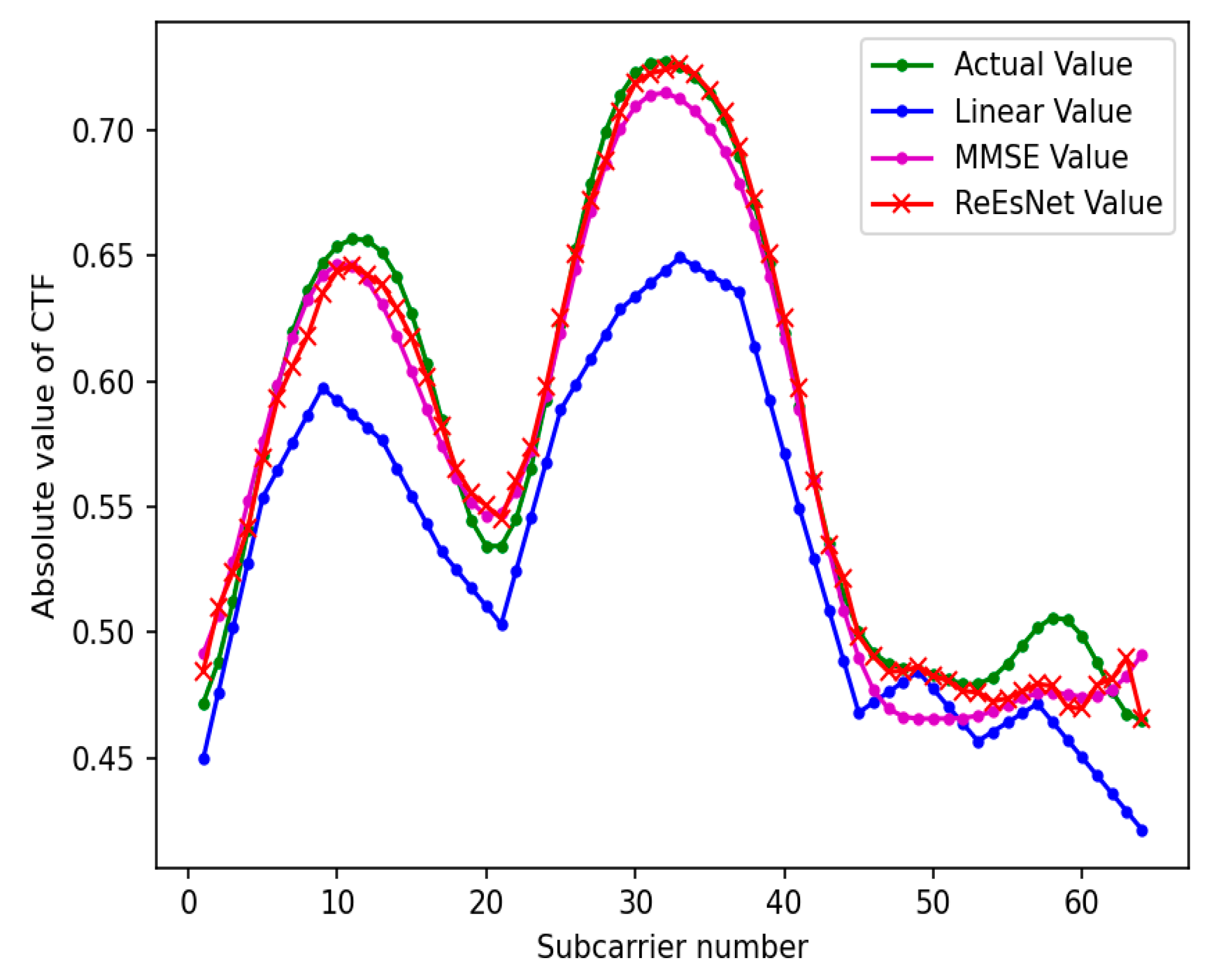
Figure 10 is the contrast map of 64 subcarrier channel estimation under the mine. In this simulation, the number of subcarriers is set to 64, the CP length is 16, the sampling interval is 5*e-8, and the relative delay is [0,1,2,3,4,5,6,7] . Directly save the subcarrier as 128 training parameters to test the channel state information comparison chart when the subcarrier is 64 is shown in
Figure 10. The superior performance of the ReEsNet interpolation approach can also be seen in
Figure 10. It is shown that deep neural network can learn to CSI with a small amount of data, and can be applied to the same channel environment with different input data to obtain good performance. Both experimental plots are local features of a sample data, next look at the overall features of the test data in the interpolation of the ReEsNet network prediction channel estimates.
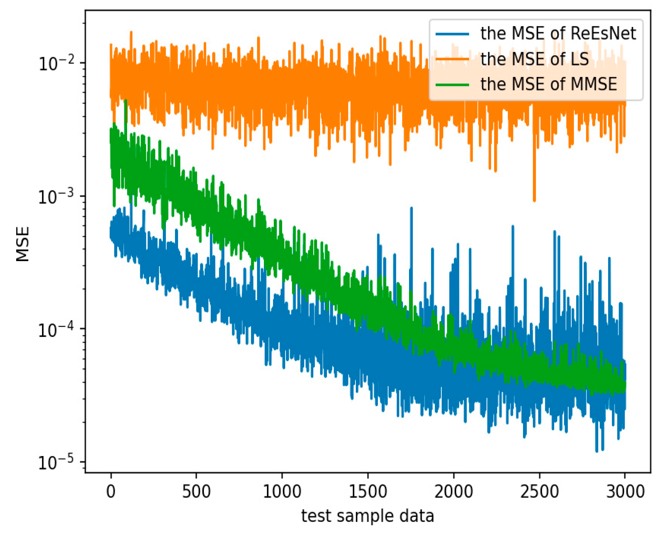
Figure 11 shows the comparison of the mean square error of 128 subcarrier channel estimation under the mine. In
Figure 11, the horizontal coordinate is the number of sample data in the test set, and the horizontal coordinate is the mean square error, which is the sum of the mean squared deviations of the channel estimates and the true CSI. It can be seen in the figure that the MSE performance of LS channel estimation is the worst, and the difference between the real and imaginary amplitude values of the two channel matrices is quite far. MMSE performance is second, and ReEsNet performance is the best. At 1500 sample data, the MSE values were 2e-2 for LS, 6e-3 for MMSE, and 8.44e-5 for ReEsNet. These above three experiments can illustrate the good performance of ReEsNet for interpolation of channel estimation in underground mines.
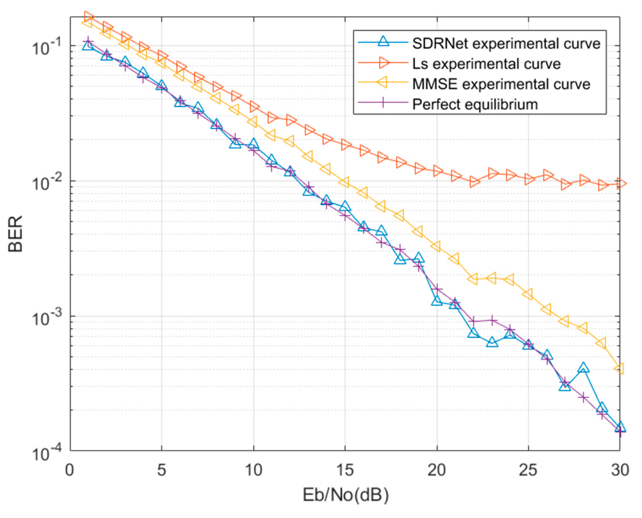
Figure 12 shows the comparison etween SDRNet signal detection method and traditional signal detection method. The data after the pilots are removed in the case of 128 subcarriers case are used as samples, and the data at the transmitter side are used as labels for network training. It is found that ttraining with the SDRNet network proposed in this paper can achieve a performance that does not differ much from the ideal conditions. It can be seen that the SDRNet proposed in this paper has good performance.
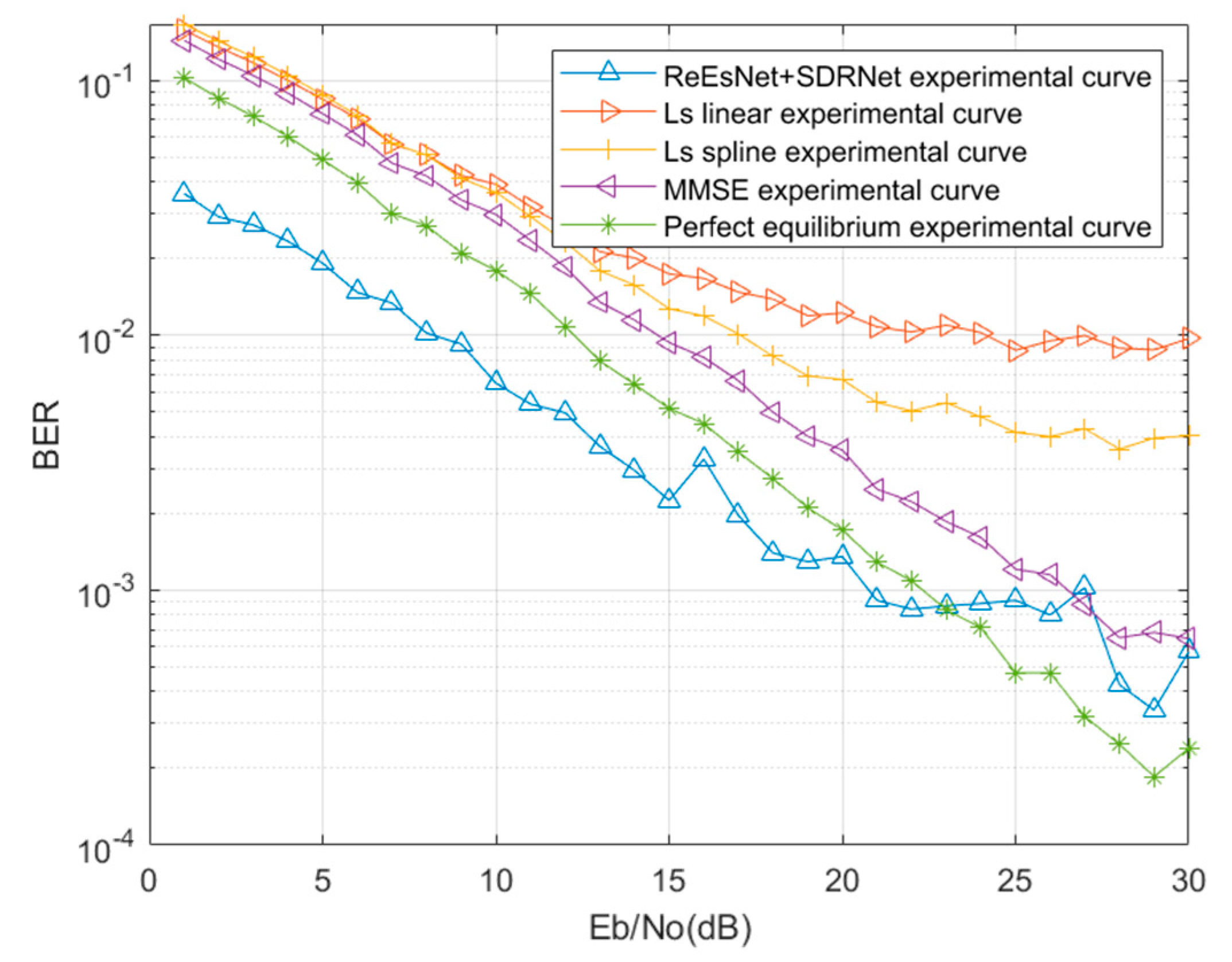
Figure 13 shows the comparison of 128 subcarrier channel estimation and signal detection methods in mine. Next, the data interpolated by the ReEsNet network are used to channel equalized and pilots removed, and then the data are fed into the SDRNet network for training. In
Figure 13, it can be found that the BER curve of SDRNet consistently outperforms the MMSE BER curve and the LS BER curve. In comparison with perfect equalization, it was found that SDRNet recovery network outperformed perfect equalization at 1-22 dB and perfect equalization outperformed SDRNet network at greater than 22 dB. This may be due to the fact that the interpolation of the ReEsNet network for channel estimation does not perform particularly well at high SNR, and subsequent consideration may be given to adaptive networks in both cases. When the SNR is 15 dB, the BER of the combined ReEsNet and SDRNet is 2.24e-3, the BER of perfect equalization is 6.03e-3, the BER of MMSE is 1.02e-2, and the BER of LS is 1.4e-2. Fig13 clearly shows the excellent performance of channel estimation and signal detection with the combination of ReEsNet and SDRNet.
In the signal detection network, the training parameters of SDRNet are compared with those of literature [
5] DNNet(Deep Neural Network) and literature [
6] CCRNet, and in Table 6 it is found that the SDRNet network proposed in this paper has the least training parameters and the shortest training time used. The CCRNet network has the most complex structure, the most trainable parameters and the longest training time. DNNet complexity performance is in the middle. SDRNet had 97% fewer trainable parameters compared to CCRNet and 84% fewer trainable parameters than DNNet. This also proves that the SDRNet network proposed in this paper can achieve better results with low structural complexity, few trainable parameters and short training time.

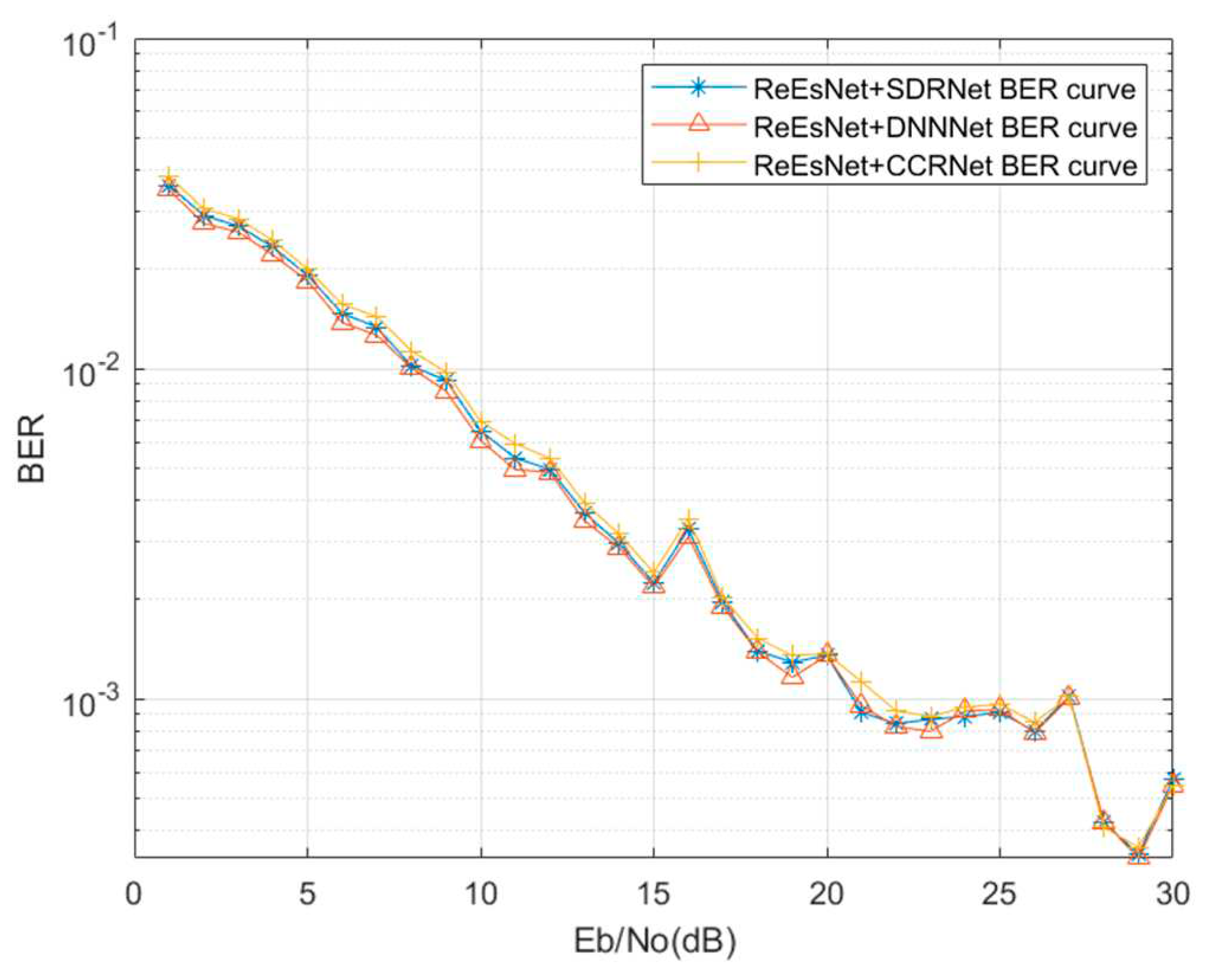
Figure 14 shows the comparison of signal detection performance under different networks. The SDRNet proposed in this paper can also achieve about the same BER performance as the CCRNet and DNNet networks. Therefore, the complexity of the SDRNet network is low, but it can maintain good error performance. It can be seen that the SDRNet network of this paper has low complexity and good BER performance. In
Figure 14, the performance of SDRNet is in the middle, but it is found that DNNet has the best performance, proving that the fully connected layer has the best performance in extracting features from the data. CCRNet has the worst bit error performance, which proves that convolution layer is not as good as full connection layer. The above simulation experiments demonstrate that the joint channel estimation and signal detection proposed in this paper outperforms the already proposed joint channel estimation and signal detection methods.
5. Conclusions
In this paper, traditional communication knowledge at the receiver side is combined with deep learning networks. A channel estimation and signal detection method based on the combination of ReEsNet and SDRNet under the mine is proposed. The simulation results are compared with the traditional receiver-side method and other joint deep learning channel estimation and signal detection methods, and the simulation results prove that the proposed method in this paper has some advantages.
The channel estimation interpolation by ReEsNet is compared with the conventional channel estimation, and ReEsNet has the best performance in the complex scenario like mine, which is closest to the real channel state information i.e., the smallest mean square error. It is proved that ReEsNet has some advantages for interpolation in channel estimation in mine environment. After the interpolation of ReEsNet channel estimation, the data are channel equalized and pilots removed and fed into SDRNet for training, The final test results show that SDRNet is better than traditional signal detection methods. Compared with the existing joint channel estimation and signal detection methods, the SDRNet network proposed in this paper has low complexity, fewer trainable parameters and less training time, and still achieves about the same detection performance. It is proved that the combined ReEsNet and SDRNet proposed in this paper have better performance in underground mines.
The proposed joint channel estimation and signal detection in complex mine scenarios has some theoretical significance and provides a new way of thanking to solve the wireless signal fading problem in mines in future practical scenarios. However, there are some problems, the detection effect is not far better than the traditional signal detection method in the case of higher SNR. In future research, we hope to propose an adaptive network that can still outperform conventional signal detection methods in the case of large SNR as well as in the case of small SNR.
Author Contributions
For research articles with several authors, a short paragraph specifying their individual contributions must be provided. The following statements should be used “Conceptualization, T.L.(Tongtong Li) and A.W.; methodology, T.L.; software, T.L.; validation, X.L., T.L. and A.W.; formal analysis, T.L.; investigation, T.L.; resources, X.L. and A.W.; writing—original draft preparation, T.L.; writing—review and editing, T.L. and A.W.; visualization, T.L.; supervision, X.L. and A.W.; funding acquisition, A.W. All authors have read and agreed to the published version of the manuscript.”.
Funding
The authors would like to thank support from the National Natural Science Foundation of China (U19B2015).
Acknowledgments
The authors would like to thank Mr. Wang, Mr. Li, all the seniors and colleagues in our group for their guidance in the graduate stage, from the initial definition of the topic, to data collection, to writing and revising, to the final draft of the thesis, they have given me patient guidance and selfless help.
Conflicts of Interest
The authors declare no conflict of interest.
References
- Sun Jiping. Coal mine intelligence and mining 5G[J]. Industrial and mining automation, vol. 46, no. 8, pp. 1-7, 2020. [CrossRef]
- S. Zheng, S. Chen and X. Yang, "DeepReceiver: A Deep Learning-Based Intelligent Receiver for Wireless Communications in the Physical Layer," in IEEE Transactions on Cognitive Communications and Networking, vol. 7, no. 1, pp. 5-20, March 2021. [CrossRef]
- B. Wang, K. Xu, P. Song, Y. Zhang, Y. Liu and Y. Sun, "A Deep Learning-Based Intelligent Receiver for OFDM," 2021 IEEE 18th International Conference on Mobile Ad Hoc and Smart Systems (MASS), Denver, CO, USA, 2021, pp. 562-563. [CrossRef]
- Y. Yıldırım, S. Özer and H. A. Çırpan, "Deep Receiver Design for Multi-carrier Waveforms Using CNNs," 2020 43rd International Conference on Telecommunications and Signal Processing (TSP), Milan, Italy, 2020, pp. 31-36. [CrossRef]
- H. Ye, G. Y. Li and B. -H. Juang, "Power of Deep Learning for Channel Estimation and Signal Detection in OFDM Systems," in IEEE Wireless Communications Letters, vol. 7, no. 1, pp. 114-117, Feb. 2018. [CrossRef]
- X. Yi and C. Zhong, "Deep Learning for Joint Channel Estimation and Signal Detection in OFDM Systems," in IEEE Communications Letters, vol. 24, no. 12, pp. 2780-2784, Dec. 2020. [CrossRef]
- T. Dai, J. Cai, Y. Zhang, S. -T. Xia and L. Zhang, "Second-Order Attention Network for Single Image Super-Resolution," 2019 IEEE/CVF Conference on Computer Vision and Pattern Recognition (CVPR), Long Beach, CA, USA, 2019, pp. 11057-11066. [CrossRef]
- Balevi E, Andrews J G. Deep learning-based channel estimation for high-dimensional signals[J]. arXiv arXiv:1904.09346, 2019.
- Heckel R, Hand P. Deep decoder: Concise image representations from untrained non-convolutional networks[J]. arXiv preprint arXiv:1810.03982, 2018.
- L. Li, H. Chen, H. -H. Chang and L. Liu, "Deep Residual Learning Meets OFDM Channel Estimation," in IEEE Wireless Communications Letters, vol. 9, no. 5, pp. 615-618, May 2020. [CrossRef]
- Wang A-Y, Li L. A method for underground signal identification based on higher-order accumulation and DNN model[J]. Industrial and mining automation, vol. 46, no. 2, pp. 5-20, 2020. [CrossRef]
- T. O’Shea and J. Hoydis, "An Introduction to Deep Learning for the Physical Layer," in IEEE Transactions on Cognitive Communications and Networking, vol. 3, no. 4, pp. 563-575, Dec. 2017. [CrossRef]
- H. Mao, H. Lu, Y. Lu and D. Zhu, "RoemNet: Robust Meta Learning Based Channel Estimation in OFDM Systems," ICC 2019 - 2019 IEEE International Conference on Communications (ICC), Shanghai, China, 2019, pp. 1-6. [CrossRef]
- Y. Zhang, Y. Mu, Y. Liu, T. Zhang and Y. Qian, "Deep Learning-Based Beamspace Channel Estimation in mmWave Massive MIMO Systems," in IEEE Wireless Communications Letters, vol. 9, no. 12, pp. 2212-2215, Dec. 2020. [CrossRef]
- Z. Zhou, L. Liu and H. -H. Chang, "Learning for Detection: MIMO-OFDM Symbol Detection Through Downlink Pilots," in IEEE Transactions on Wireless Communications, vol. 19, no. 6, pp. 3712-3726, June 2020. [CrossRef]
- Wang Z, Chen J, Hoi S C H. Deep learning for image super-resolution: A survey[J]. IEEE transactions on pattern analysis and machine intelligence, 2020, 43(10): 3365-3387.
- M. R. Mathews and S. M. Anzar, "Residual Networks and Deep-Densely Connected Networks for the Classification of retinal OCT Images," 2022 International Conference on Connected Systems & Intelligence (CSI), Trivandrum, India, 2022, pp. 1-7. [CrossRef]
- X. Mao, Y. Chen, Y. Li, T. Xiong, Y. He and H. Xue, "Bilinear Representation for Language-based Image Editing Using Conditional Generative Adversarial Networks," ICASSP 2019 - 2019 IEEE International Conference on Acoustics, Speech and Signal Processing (ICASSP), Brighton, UK, 2019, pp. 2047-2051. [CrossRef]
|
Disclaimer/Publisher’s Note: The statements, opinions and data contained in all publications are solely those of the individual author(s) and contributor(s) and not of MDPI and/or the editor(s). MDPI and/or the editor(s) disclaim responsibility for any injury to people or property resulting from any ideas, methods, instructions or products referred to in the content. |
© 2023 by the authors. Licensee MDPI, Basel, Switzerland. This article is an open access article distributed under the terms and conditions of the Creative Commons Attribution (CC BY) license (http://creativecommons.org/licenses/by/4.0/).


