1. Introduction
As a thermoplastic polymer, PMMA has good mechanical properties such as anti-aging, light weight, high transparency and impact resistance. In today's rapidly developing technology, with the speed of ocean development and aviation exploration, it is widely used in various fields such as mechanical manufacturing, construction, aviation, and biomedical applications. Currently, ocean exploration and the development of deep-sea equipment are receiving increasing attention from countries around the world, and have become a key development focus in the deep-sea field. For deep-sea equipment, transparent structures are increasingly being applied to meet the current multifunctional development needs of deep-sea vehicles [
2]. As important components of deep submersibles, such as transparent cabins or observation windows, structural design calculation methods for their strength or fatigue life are currently mainly based on theory, numerical or experimental research [3-6]. In the complex marine environment and the current competitive situation of ocean competition among countries around the world, collisions and impacts of deep-sea equipment are inevitable.
In impact analysis, the material properties of collision structures have a significant impact on the impact process and results, such as the constitutive model and damage model characteristics of materials. The Johnson Cook constitutive model and damage failure model [
7] are theoretical methods proposed by two scholars, Johnson and Cook, in the 1980s and widely used in the field of impact collision. In their research, Johnson and Cook conducted tensile and torsional tests on 12 materials at different strain rates and temperatures, and determined the J-C constitutive model parameters of these materials through numerical simulation and comparison of experimental results. In addition, they also proposed a fracture criterion that considers the effects of large strain, high temperature, and high stress, and verified it through Taylor impact tests and numerical simulations. Liu [
8] and others expressed the physical constitutive equation of normalized 50SiMnVB steel according to the J-C model, and the strain rate range is from quasi-static to dynamic. Guo [
9] modified the temperature softening term in the J-C constitutive model based on experimental results and proposed a modified J-C constitutive model for Q235 steel. For PMMA materials, Yu[
10] on ducted SHPB experiments to study the dynamic mechanical properties of PMMA at room temperature. Yao [
11] conducted compression experiments on organic glass specimens under quasi-static and impact conditions using an INSTRON electronic universal testing machine and a separate Hopkinson compression rod device. Wang [
12] obtained the constitutive relationship of organic glass by studying the effect of temperature on the quasi-static tensile mechanical properties of organic glass thick plates, using the nonlinear elastic partial expression of the ZWT model. Paul Moy et al. studied the room temperature uniaxial compression strain rate response of PMMA in the strain rate range of 0.0001s-4300s-1. N. A. Kazarinov [
14] conducted experimental research on the velocity of PMMA thin plates under high-speed steel projectile penetration using LS-DYNA. Wu [
15] conducted experimental studies on the quasi-static and medium strain rate uniaxial tensile mechanical properties of PMMA using the MTS810 testing machine and the self-developed medium strain rate material testing machine. For the damage behavior of the J-C failure model, Chen [
16] conducted quasi-static material mechanical properties experiments and tensile SHPB experiments on 45 steel under different stress states and temperatures, and determined the parameters of the J-C failure model through experimental data. Zeng [
17] et al., based on the theory of Damage mechanics, conducted an experimental study on the nonlinear mechanical properties of PMMA under uniaxial tension, and proposed an improved Maxwell model that can describe the strain rate dependent and viscoelastic damage behavior of PMMA to reveal the impact resistance of PMMA materials.
Therefore, this article aims to study the structural performance of underwater transparent pressure resistant shells under impact, focusing on numerical simulation models based on J-C constitutive and damage models. The J-C constitutive and damage models of PMMA materials are determined through material test data and least squares method, and verified through PMMA plate shell structure impact tests. Finally, the impact performance of pressure resistant structures under static water pressure under impact is revealed.
2. Problem and structural modeling
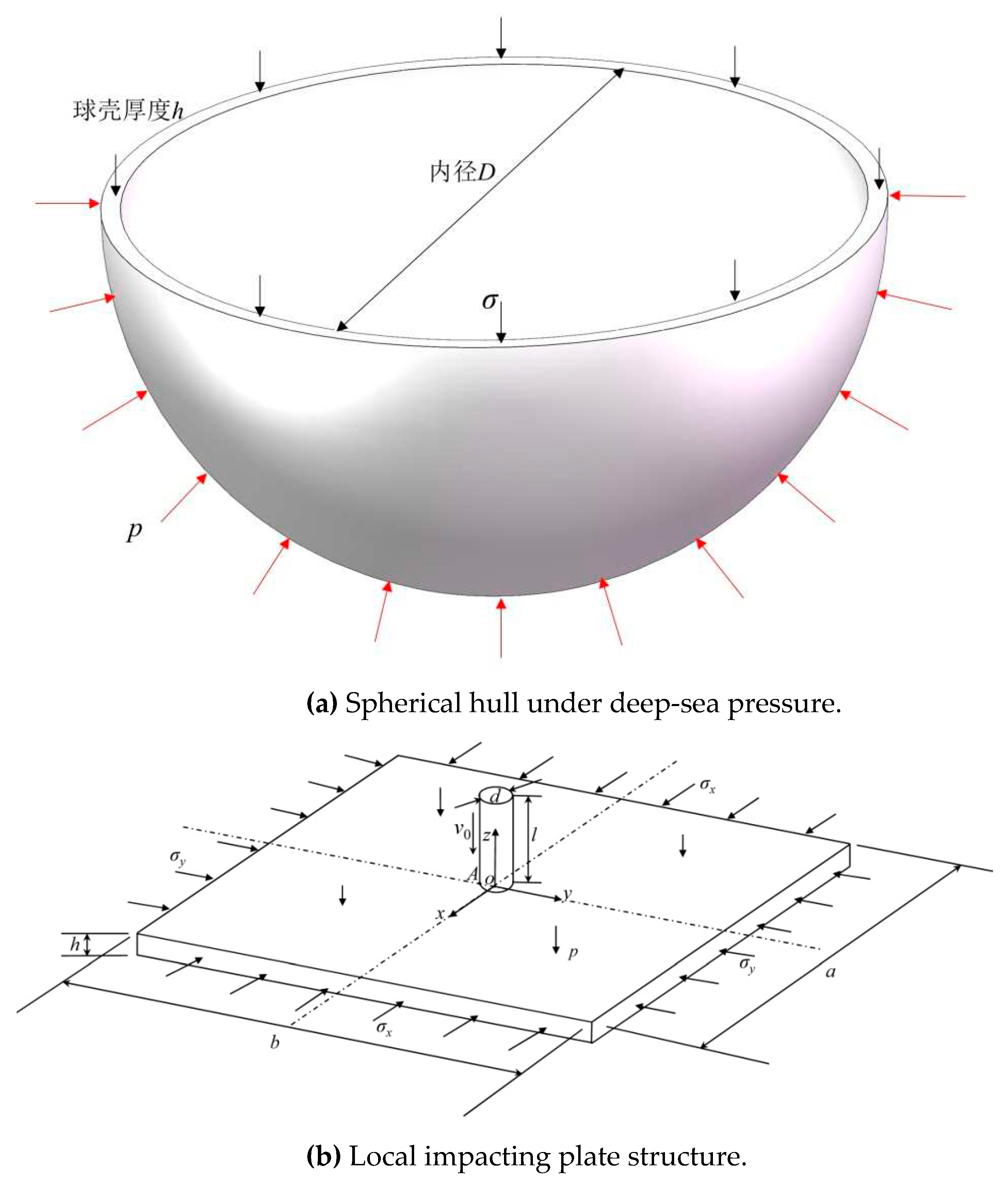
In underwater engineering, especially in deep sea engineering, due to the advantages of uniform force distribution, spherical structures are one of the most commonly used pressure resistant structures, as shown in
Figure 1 (a).
In order to simplify the impact problem of spherical shells for research purposes, this article will focus on the dynamic situation of concentrated impact spherical shell structures, where the size of the impact body (projectile) is relatively small compared to the spherical shell structure. Therefore, in the local size region, the spherical shell surface is simplified as a flat plate structure impacted by the projectile and the structural model is shown in
Figure 1 (b).
The meanings of various structural parameter variables are defined respectively as, in Figure (a) D is the diameter of sphere while h is the thickness of sphere, p is the acting external pressure and σ is the internal stress under loading. In Figure (b), a and b are length of block in x and y direction (the coordinate system is shown as figure), while h is the thickness of block which is equal to that thickness of sphere. Moreover σx and σy are the internal stress of plate in two axis direction under acting pressure p. d and l are the diameter and length of steel bullet with initial velocity v0.
3. J-C constitutive model and damage failure model
Generally, in finite element collision simulation analysis, different models are used for the constitutive and damage models of PMMA [18, 19], while Johnson Cook explored the unity of material constitutive and damage models.
3.1. J-C constitutive model
The Johnson Cook constitutive model focuses on describing the nonlinear stress-strain relationship of materials entering hyperelasticity, and the specific expression is as follows [
2]
In the formula, σ is the stress; ε is the plastic strain; Represents the strain rate (); T* represents the relative dimensionless temperature parameter at the current temperature (T*=(T-Tr)/(Tm-Tr)), where Tr is the room temperature and Tm is the reference temperature. The physical meaning of each parameter is: A represents the yield strength of the material; B and n represent material strain strengthening parameters; C represents the empirical strain rate sensitivity coefficient; M represents the temperature softening effect; It is the reference strain rate of the constitutive model, usually taken as the strain rate of 10-3s-1 in quasi-static state.
When the temperature effect is not considered, the temperature remains at room temperature, that is, at this point, equation (1) of the J-C model will become
Based on the tensile/compressive test data of materials under different strains at room temperature, the least squares method can be used to determine the parameters of the J-C constitutive model of materials at room temperature. Under room temperature conditions, the values of A, B, and n are determined based on the curves obtained from material compression/tensile tests at strain rates. At this point, equation (2) becomes
Take the logarithm of both ends of equation (3), with
And let
,
, by substituting it into equation (3), we obtain
Similarly, for the initial plastic strain moment (
ε=0) at different strain rates, i.e. equation (2) becomes
By substituting
z=
ε/
A-1 into equation (7), it can be obtained that
Therefore, using the least squares method for data processing of equations (5) and (8) can ultimately determine parameters A, B, n, and C.
3.2. J-C damage model
According to the definition of the J-C damage model [
7], considering the effects of stress triaxiality, strain rate, and temperature, the model parameters have clear meanings and can be determined through experiments. Therefore, it is widely used in many studies related to material failure and failure. The J-C model first defines damage as
In the equation, D is the damage parameter factor, with a range of 0 to 1. At the beginning, D=0. When D=1, the material begins to fail, Δεp is the plastic strain increment within a time step, and εf is the failure strain under the combined action of the current time step stress state, strain rate, and temperature. The equivalent plastic strain expression at the beginning of the damage is as follows [
7]
Here D1-D5 is the failure parameter of the material, while σ*=pt/σeff=- σkk/σeff =- Rσ, pt is the pressure, σeff is the equivalent stress, Rσ is the stress triaxiality, is the dimensionless plastic strain rate, is the reference plastic strain rate, T* is the same as equation (1)
For the damage model equation (9), the first term reflects the influence of stress triaxiality, which is expressed in exponential form and controlled by D2 and D3. The equivalent plastic strain at the beginning of most material damage decreases with the increase of stress triaxiality, so a positive value D3 is often taken. Compared with the commonly used equivalent strain failure rule, this model can more effectively reflect the effect of tensile and compressive stress on material failure. The failure effect becomes smaller during tension, and the opposite is true. During compression, the failure strain is relatively large.
The second item reflects the influence of strain rate. Under the same stress state, the failure strain is linearly related to the logarithm of strain rate. By adjusting parameter D4, a practical relationship between strain rate and failure strain can be obtained.
The third item reflects the influence of temperature, and at the same strain rate, the failure strain is linearly related to dimensionless temperature.
4. Collision finite element model
This article applies the Lagrange method [
20] in the finite element simulation analysis of simulated collision processes, which applies the material J-C constitutive and damage failure models discussed in the previous section to the high-speed collision process, fully considering the collision contact boundary and energy loss.
According to the simplified model of the second water-saving collision problem - the model of square plates being impacted by bullets, and for the study of PMMA square plates being impacted by bullets, N.A. Kazarinov [
14] studied the impact test and numerical simulation of this problem in air. Test PMMA board size:
a=
b=100mm,
h=4mm-10mm; Bullet size:
d=6mm and
l=20mm, as shown in
Figure 1. The mechanical and physical properties of PMMA sheets and steel bullet materials are shown in
Table 1.
Therefore, in order to verify the accuracy of the impact method based on J-C constitutive and damage failure models constructed in this article, a finite element model with corresponding geometric dimensions was established based on the ABAQUS platform [
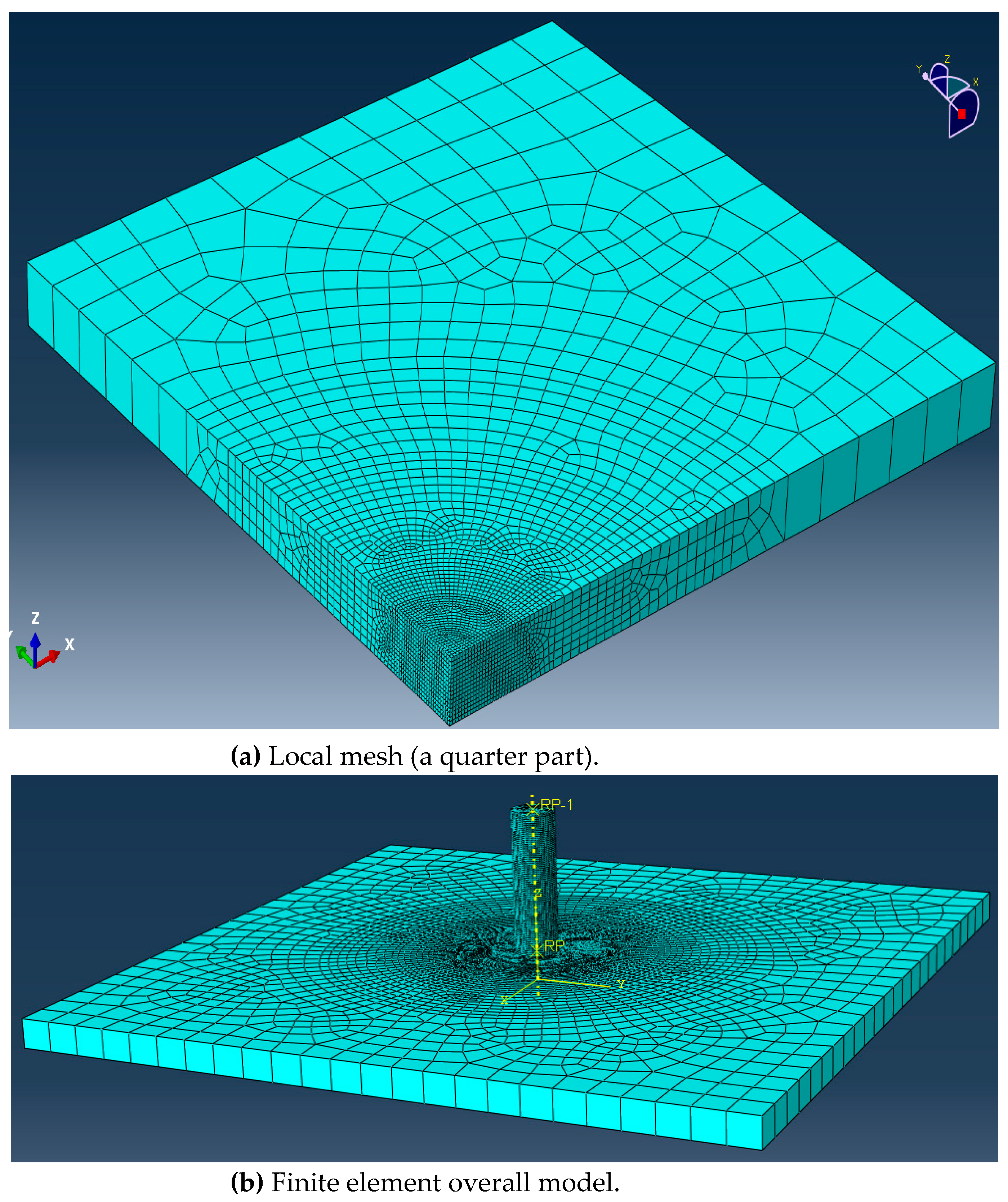
14]. Three dimensional solid elements were selected, and the local division of the finite element model mesh and the overall model are shown in
Figure 2. In order to better simulate the damage and fracture of materials in the impact area, the central element mesh of the square plate is fine. In the finite element simulation research, the boundary constraint conditions of PMMA board are shown in
Table 2. Compared to PMMA plates, bullets are rigid bodies with only axial degrees of freedom (velocity) perpendicular to the plane direction of the plate.
5. Verification of collision finite element method (CFEM)
Based on the J-C constitutive and damage failure models mentioned above, this article uses the least squares method to determine the parameters of the material based on experimental data, and compares the correctness of the analysis methods and parameters. The finite element impact process analysis of the square plate finite element model is also verified.
5.1. Verification and parameter determination of J-C constitutive model
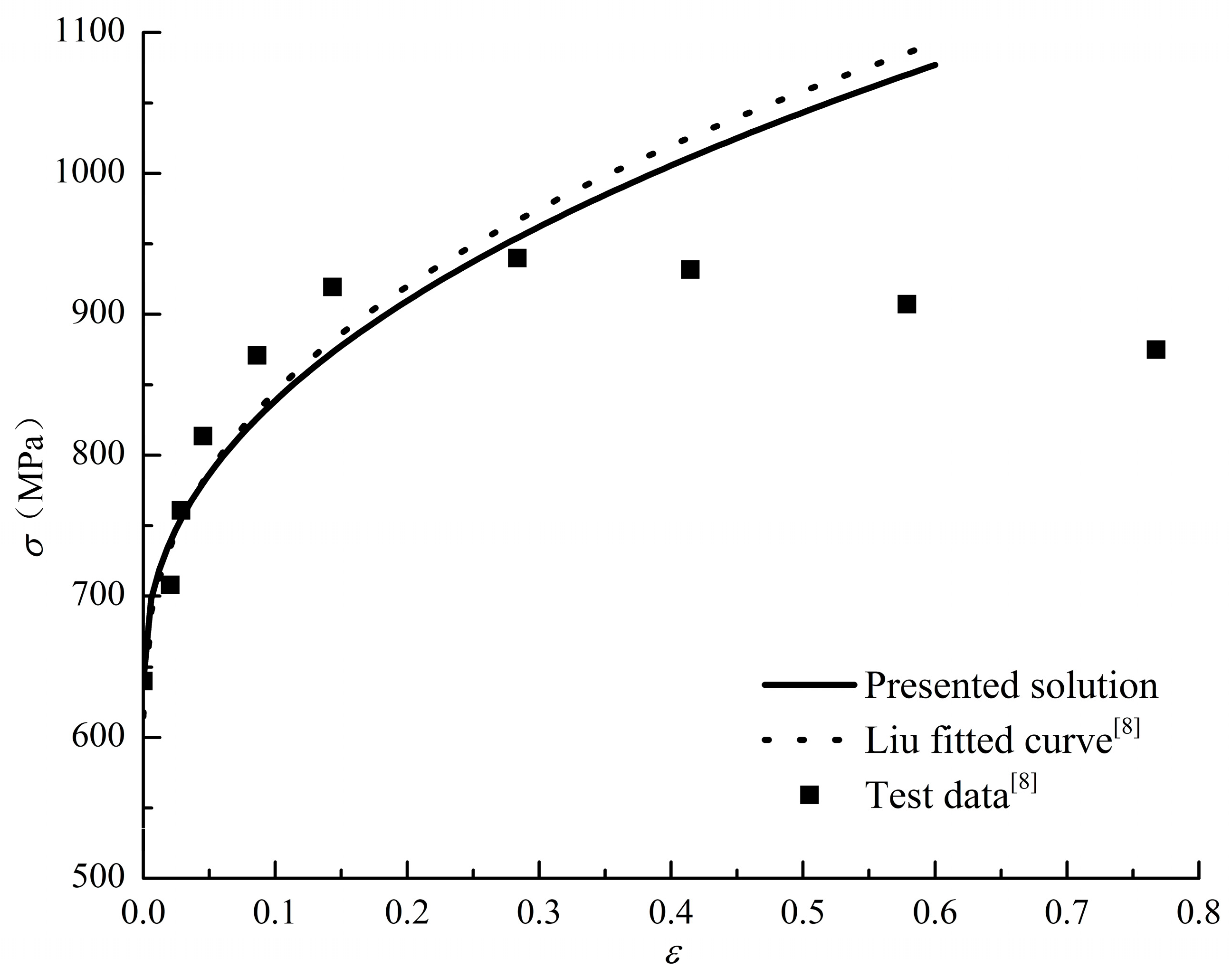
In order to verify the accuracy of the J-C constitutive model and the least square method parameter determination method, this paper first obtains the parameters of the J-C constitutive equation by normalizing the Tensile testing data of 50SiMnVB steel at different strain rates, and through the theory and data processing analysis in Section III, as shown in
Table 2, the model parameters corresponding to the strain rate of 10-3s-1 are given. Similarly, for the PMMA compression test data, the corresponding J-C constitutive model parameters can be obtained, as shown in
Table 3.
Based on the parameters and experimental data, the J-C model and experimental curves of the above two materials were compared and analyzed, as shown in
Figure 3 and
Figure 4. From the figure, it can be seen that the J-C model has a good fit with the experimental values, especially in the initial stage of plastic strain.
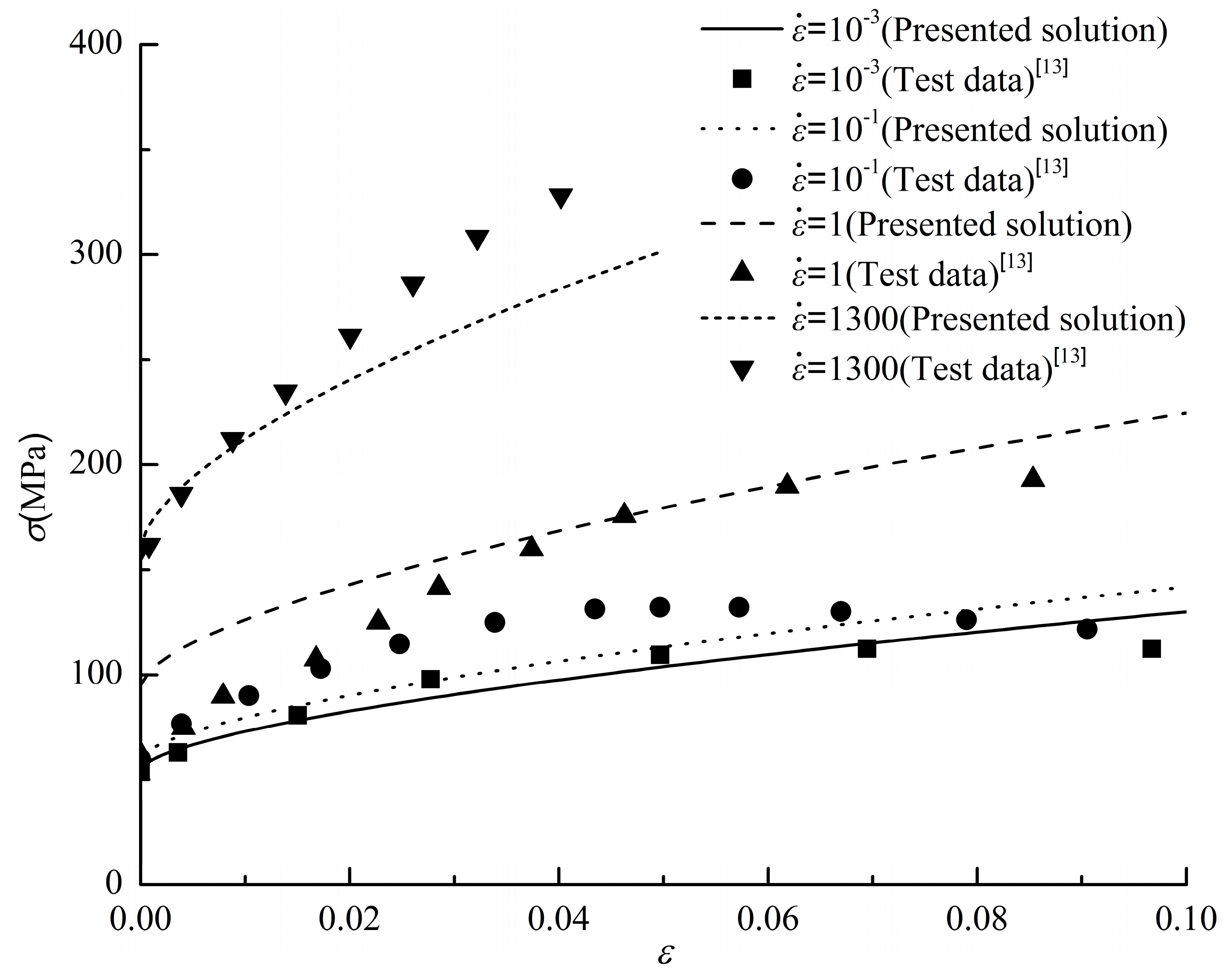
Due to the varying speed of strain changes during the process of structural breakdown during impact, the strain rate varies. Therefore, for PMMA materials with different strain rates, the J-C model was compared and analyzed with experimental values, as shown in
Figure 5. As shown in the figure, for PMMA materials, the J-C model can characterize the plastic or viscoelastic properties of the material within a certain range under different strain rates, with good accuracy.
5.2. Verification and parameter determination of J-C constitutive model
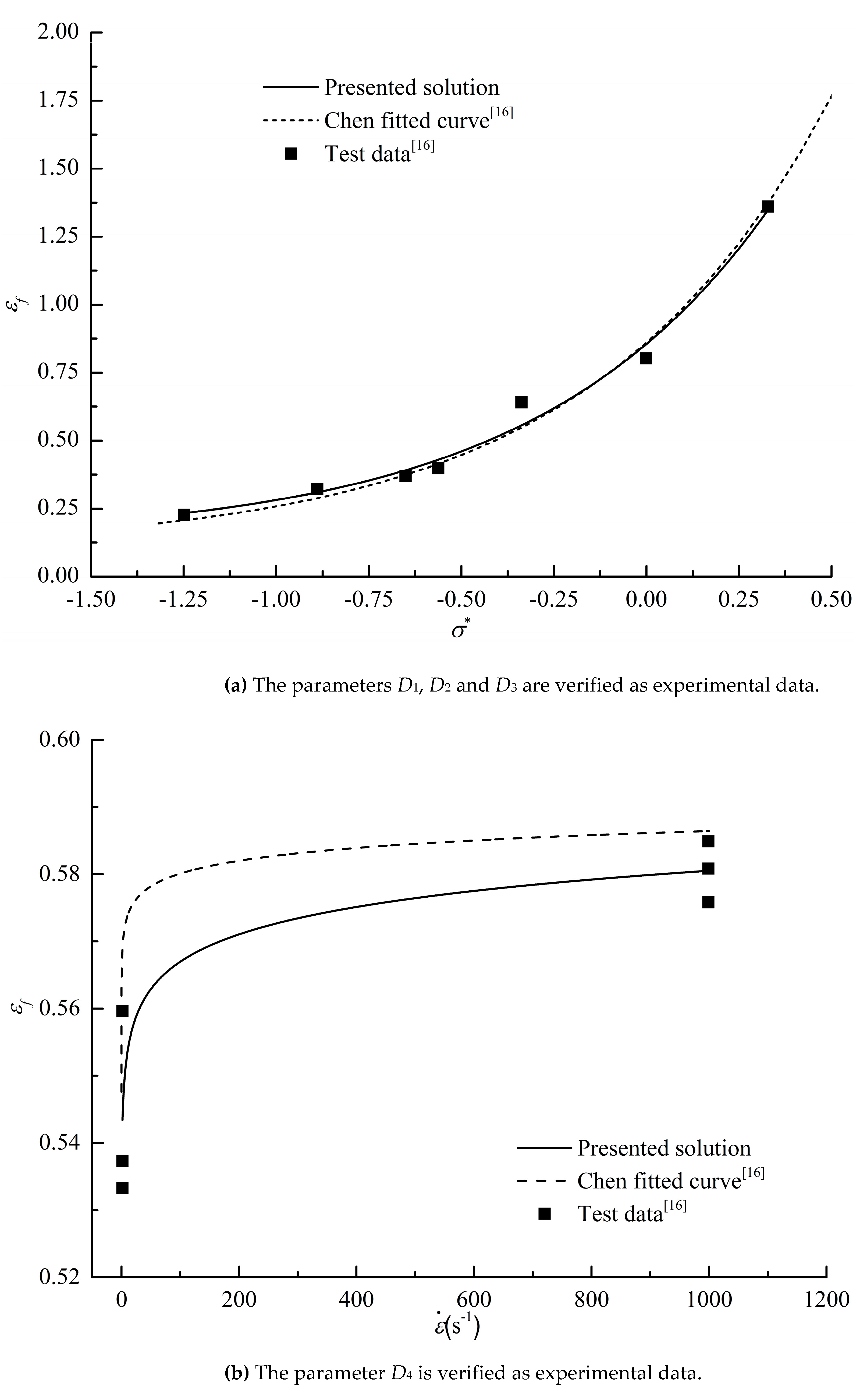
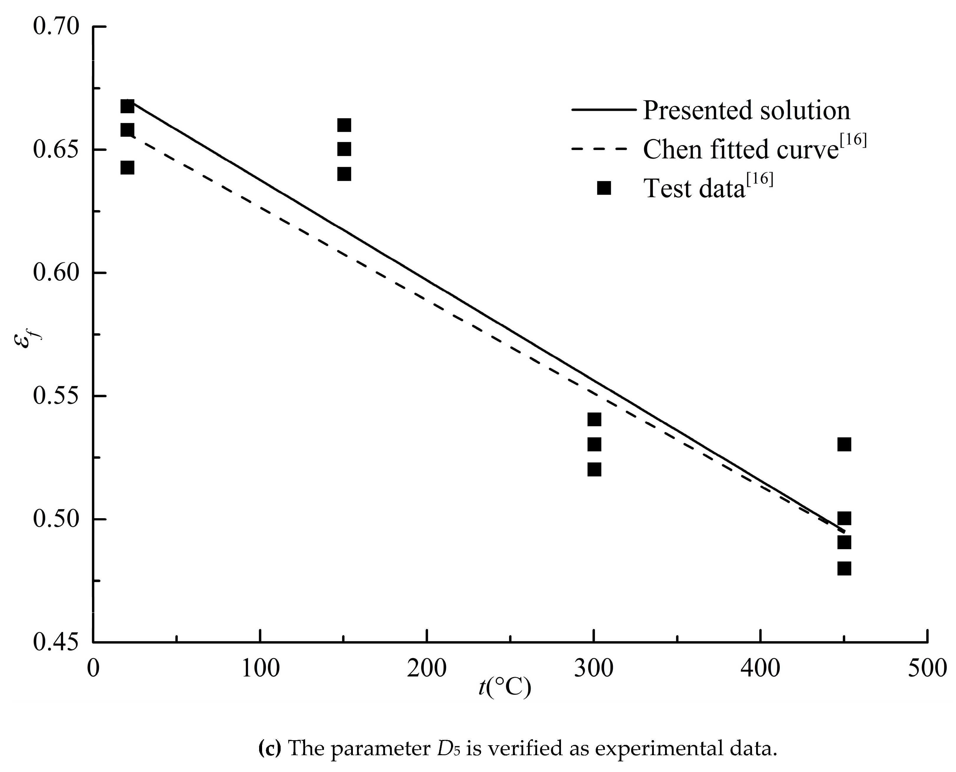
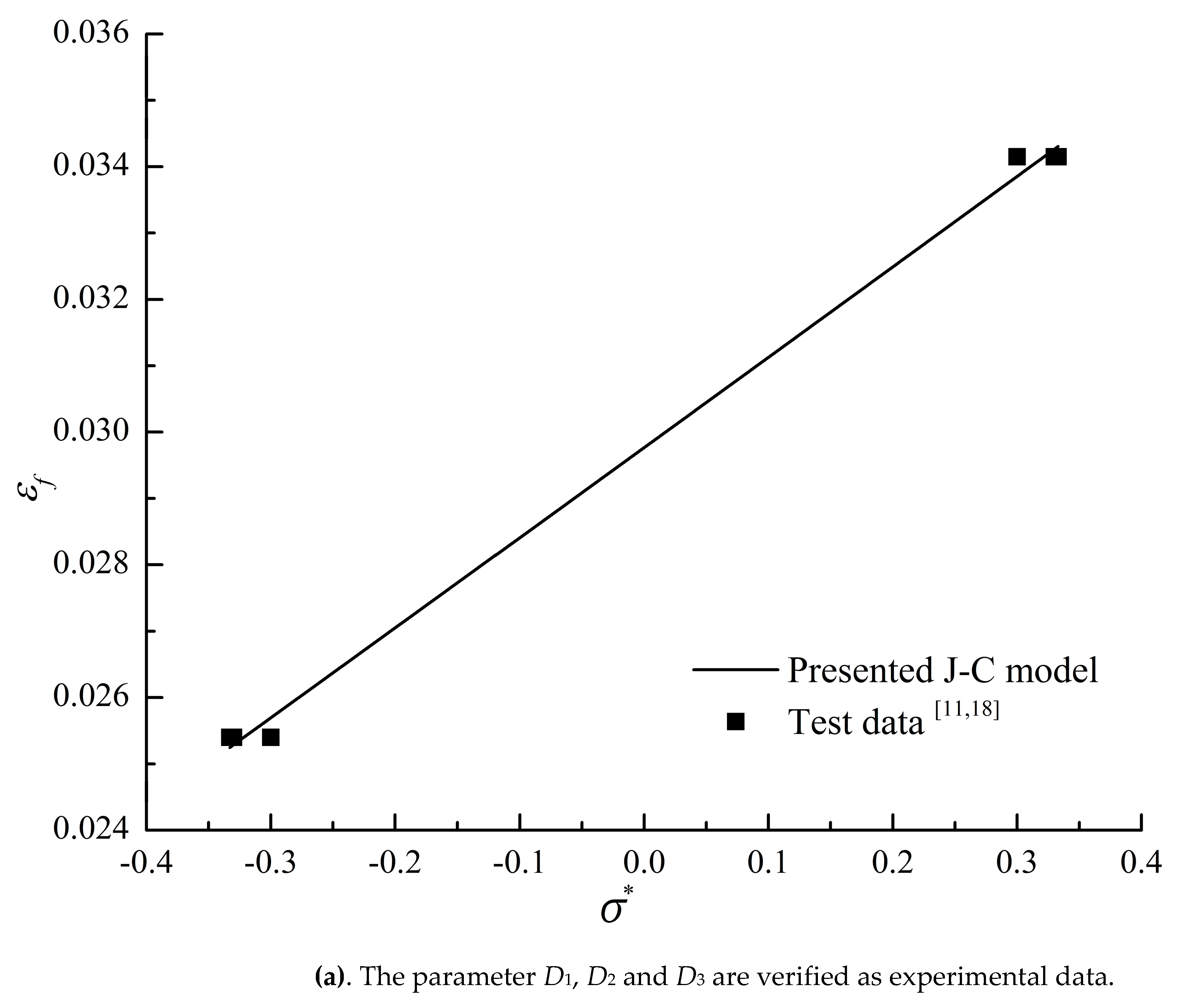
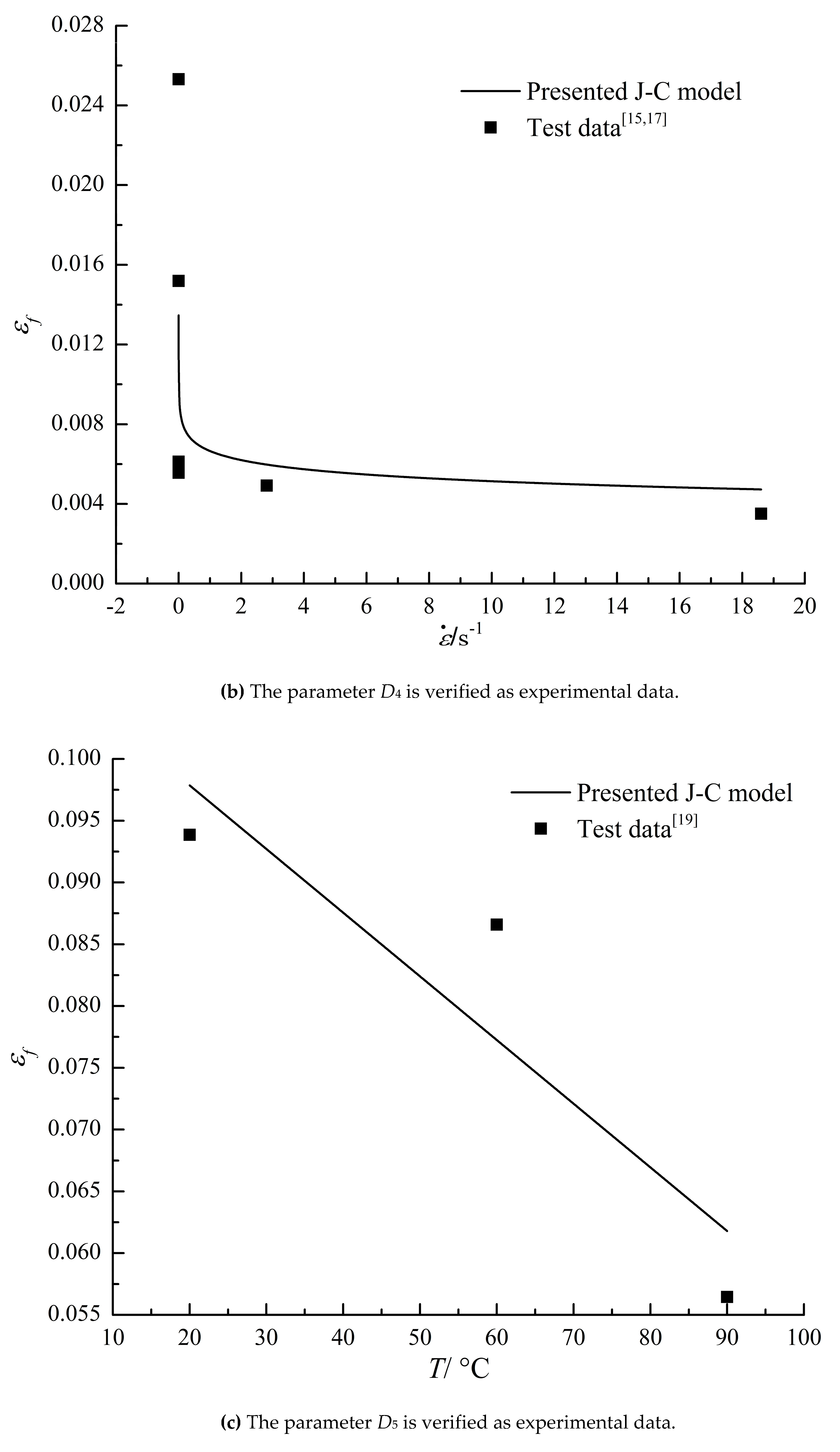
For the J-C damage failure model, this paper uses the previous least square method to determine the parameters of the J-C damage failure model from the quasi-static mechanical property experiment and compression SHPB experiment data of material specimens under different stress states and temperatures, that is, D1, D2 and D3 are determined from the quasi-static triaxial stress fracture test, and D4 and D5 are determined from the fracture test under different strain rates and temperatures. Therefore, the J-C damage failure model parameters of 45 steel obtained in this article are shown in Table 4.
From Table 4, it can be seen that the parameters determined by the least squares method in this article are basically consistent with the literature values. At the same time, based on the parameters and experimental data determined in this article, a comparative analysis was conducted on the J-C damage failure model and experimental data of 45 steel, as shown in
Figure 6,
Figure 7 and
Figure 8. From the figure, it can be seen that the J-C damage model has a good agreement with the experimental values.
Similarly, according to the above methods, the quasi-static Tensile testing and compression test [10, 18] of smooth round bar at room temperature, quasi-static Tensile testing of smooth round bar at different temperatures, Tensile testing of smooth round bar at different strain rates and other test data were processed, and the J-C damage failure model parameters of PMMA materials were finally determined. The specific parameter values are shown in Table 4.
5.3. Experimental verification of collision numerical simulation method
The J-C constitutive model and damage failure model parameters of PMMA are established through the previous section. The finite element modeling is carried out for the test block with h=4mm. The entire impact process and the residual velocity of the bullet, vr, can be calculated by applying the boundary constraints of the plate and the initial condition v0 of the bullet.
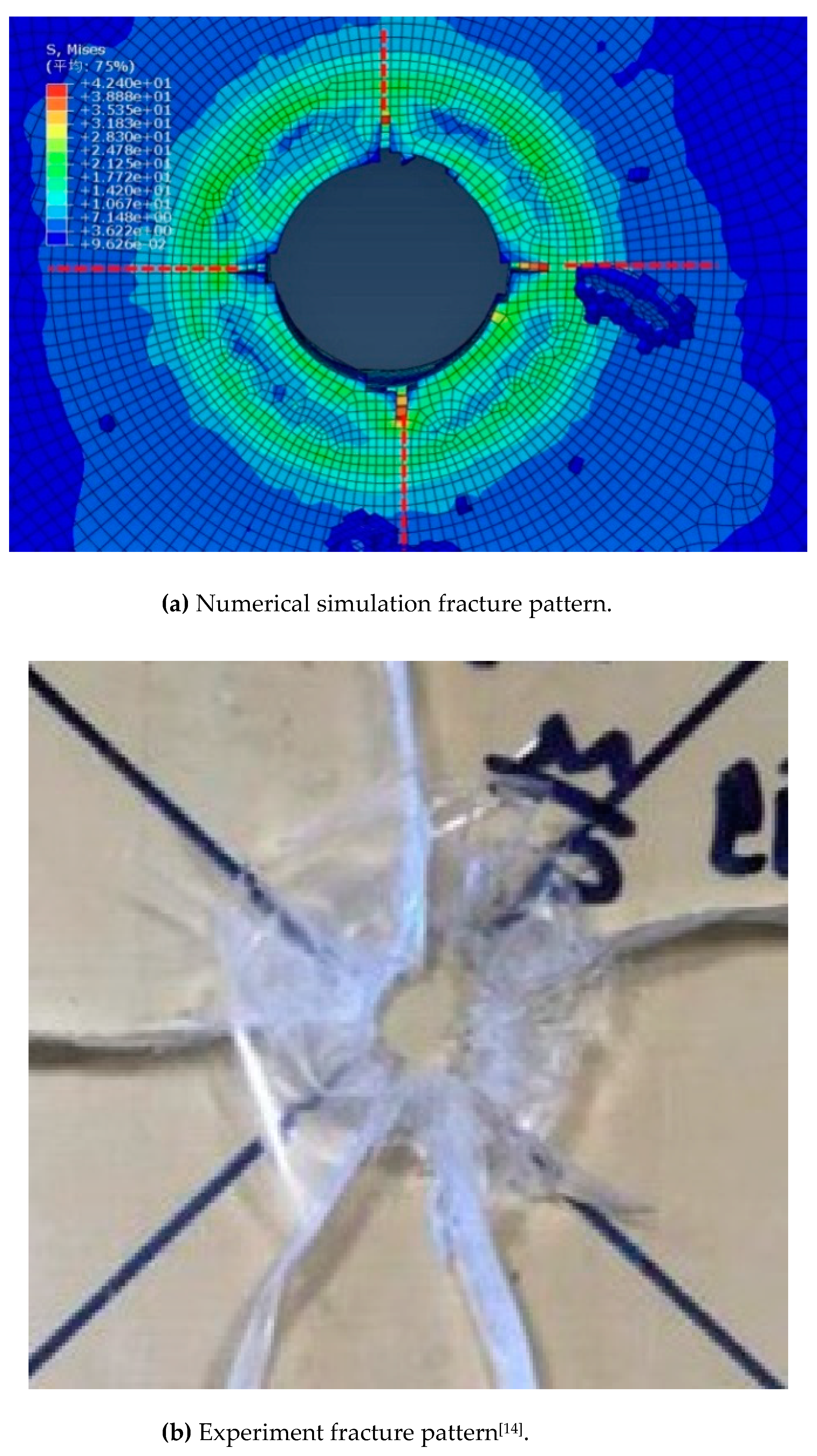
Figure 8 shows a comparison between the numerical simulation calculation of the damage caused by the bullet
v0=70m/s impacting and penetrating the PMMA plate (h=10mm) and the test [
14]. From
Figure 8, it can be seen that the finite element simulation calculation and test damage show a cross cracking trend.
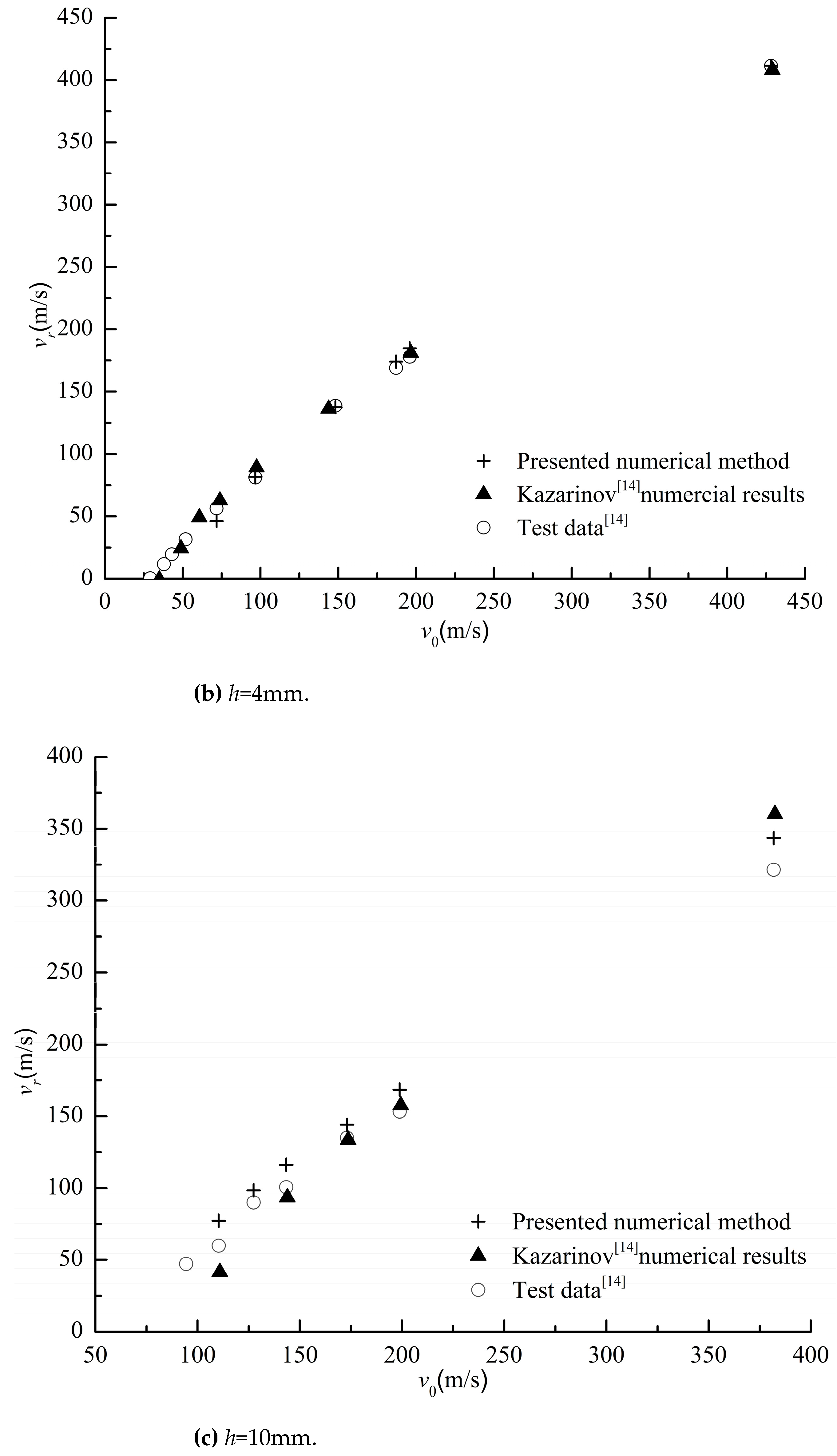
Figure 9 shows the relationship between the initial velocity and residual velocity of bullets penetrating PMMA plates of different thicknesses, and compares them with the numerical solutions and experimental values in the literature [
14]. From
Figure 9, it can be seen that the calculation results of the finite element method based on J-C constitutive and damage models constructed in this article are in good agreement with the experimental results. Therefore, the analysis results indicate the rationality and accuracy of the numerical simulation calculation method constructed in this paper.
6. Impact analysis of PMMA plate under pressure
For the problem of underwater penetration by concentrated loads, based on the simplification of the previous section, this paper studies the problem of plate penetration by concentrated loads. According to the shell theory, the internal stress
σ of the spherical structure of a carrier or deep submersible under external uniform pressure is
Therefore, in order to consider the response of external pressure and simulate the membrane stress state of underwater pressure resistant spherical shells, in the simplified finite element simulation calculation of plate structure in the previous section, the surface pressure
p effect of the square plate will be added here, and in addition to applying displacement constraints on the boundary, internal force stress boundary conditions still need to be added, that is, in
Table 2, the compressive stress
σx is added at
x=
a/2:
And at
y=
b/2, adding the compressive stress
σy
To increase comparability, the size of the PMMA square plate in the previous section was applied to the deep-sea spherical transparent glass structure D=2000mm. A finite element model was constructed and impact dynamics calculations were conducted by integrating J-C constitutive and damage failure models. Finally, the dynamic response of the PMMA square plate under pressure to bullet impact penetration was obtained.
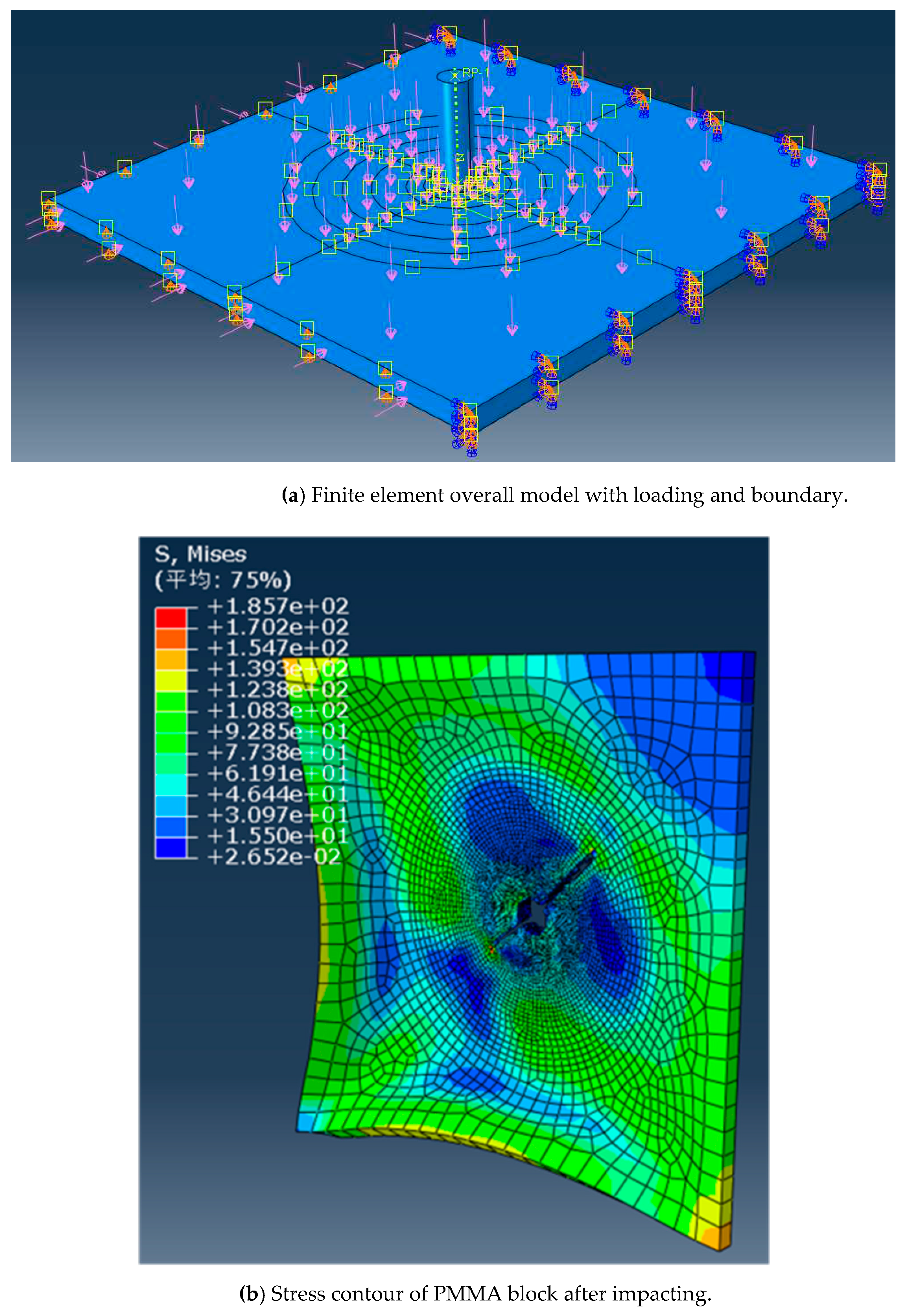
Figure 10 (a) shows the load and boundary of the finite element model, while
Figure 10 (b) shows the equivalent stress cloud and damage situation of the PMMA plate after bullet impact penetration. From the figure, it can be obviously seen that due to external pressure, the PMMA board is more severely damaged than under no pressure (
Figure 8a).
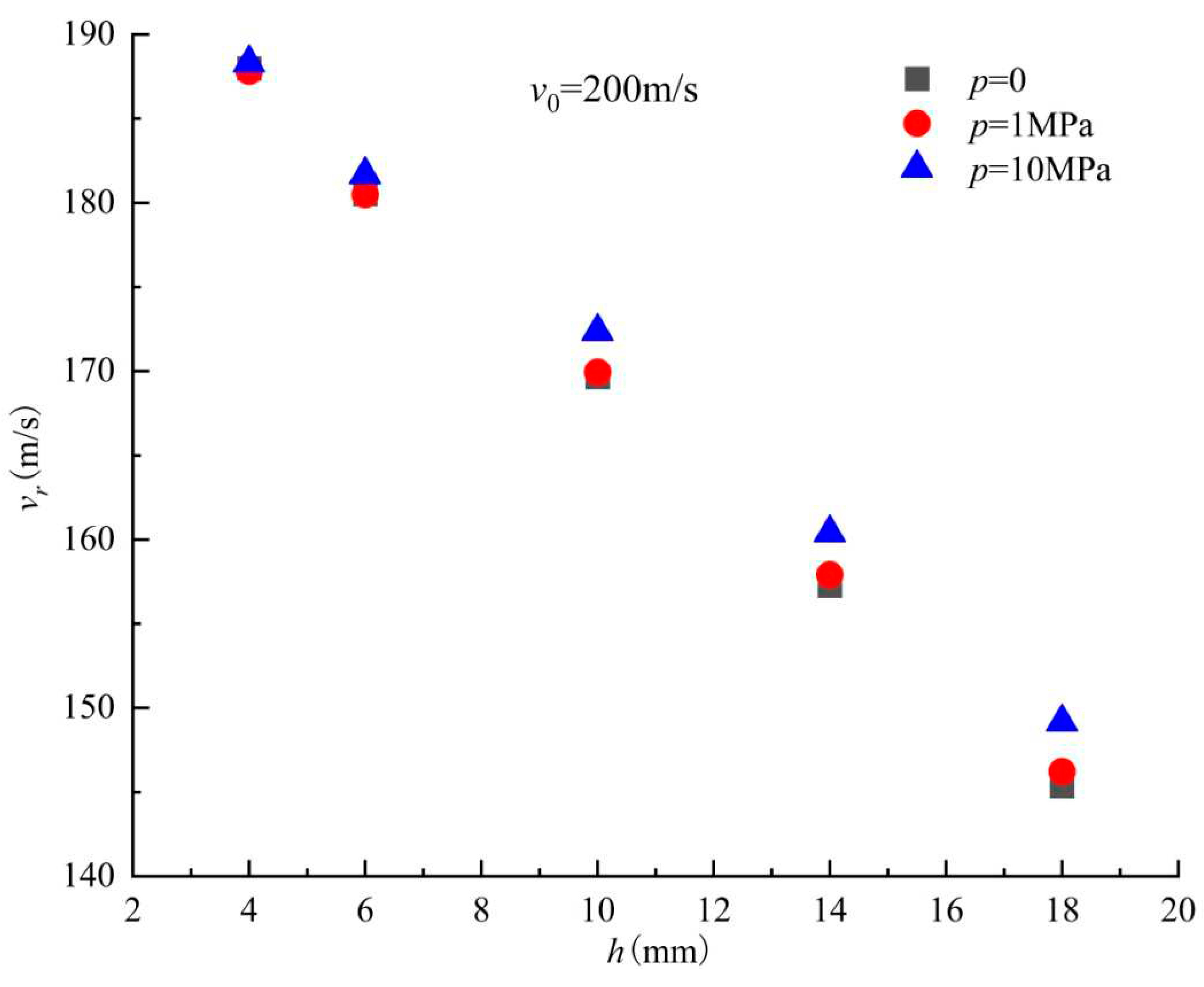
Figure 11 shows the remaining velocity of a bullet with an initial velocity of
v0=200m/s under different pressures penetrating PMMA square plates of different thicknesses. From this figure, it can be seen that as the external pressure increases, the remaining velocity of the bullet also increases, indicating that the square plate PMMA structure reduces its impact resistance to bullet penetration due to its resistance to pressure.
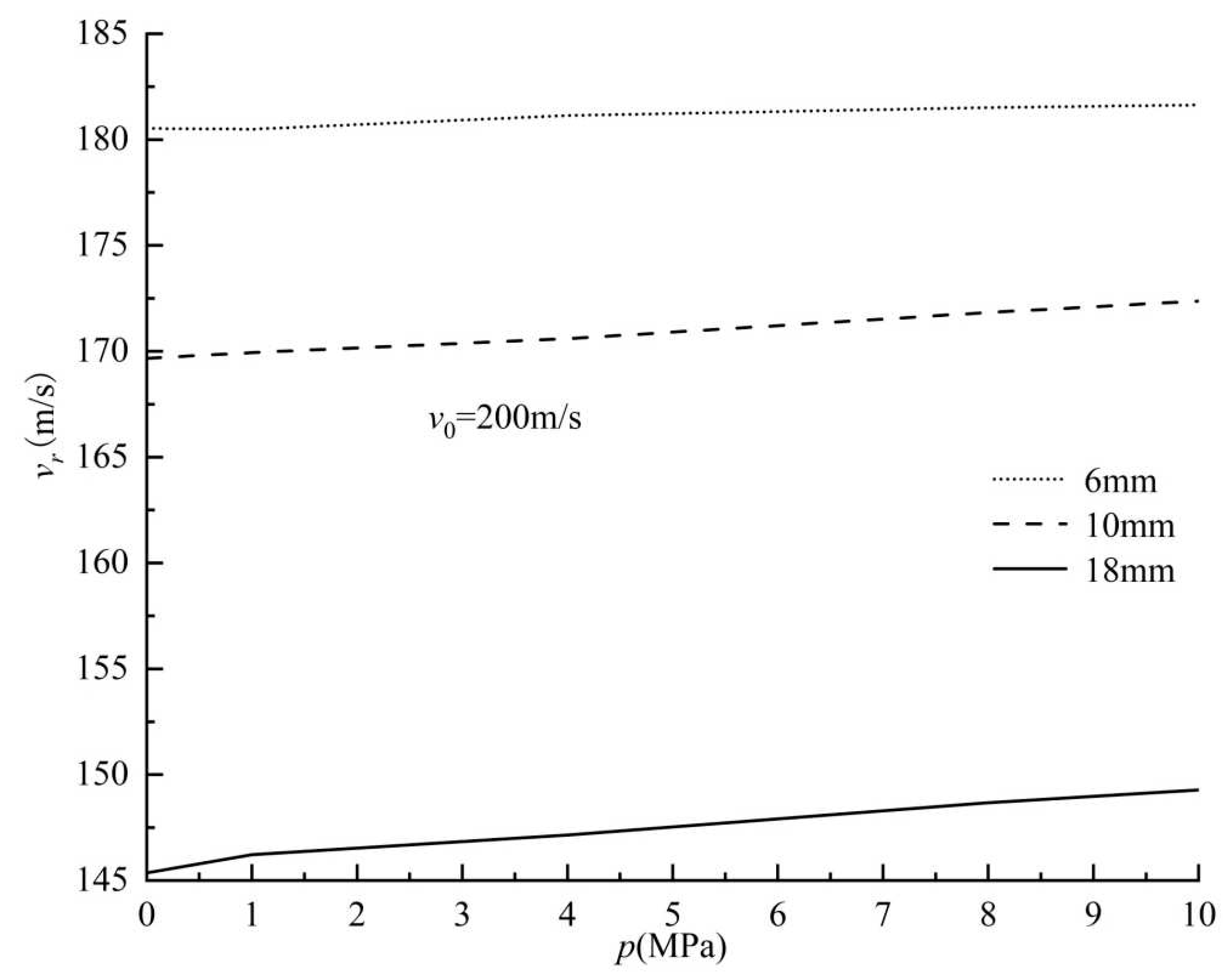
Moreover, the remaining velocity of three different thicknesses of PMMA plates under bullet impact penetration with initial velocity
v0=200m/s was studied as a function of external pressure, as shown in
Figure 12. As shown in the figure, as the external pressure increases, the remaining velocity increases, and as the thickness of the plate increases, the remaining velocity increases more severely. The effect of surface external pressure on the thick plate is more obvious.
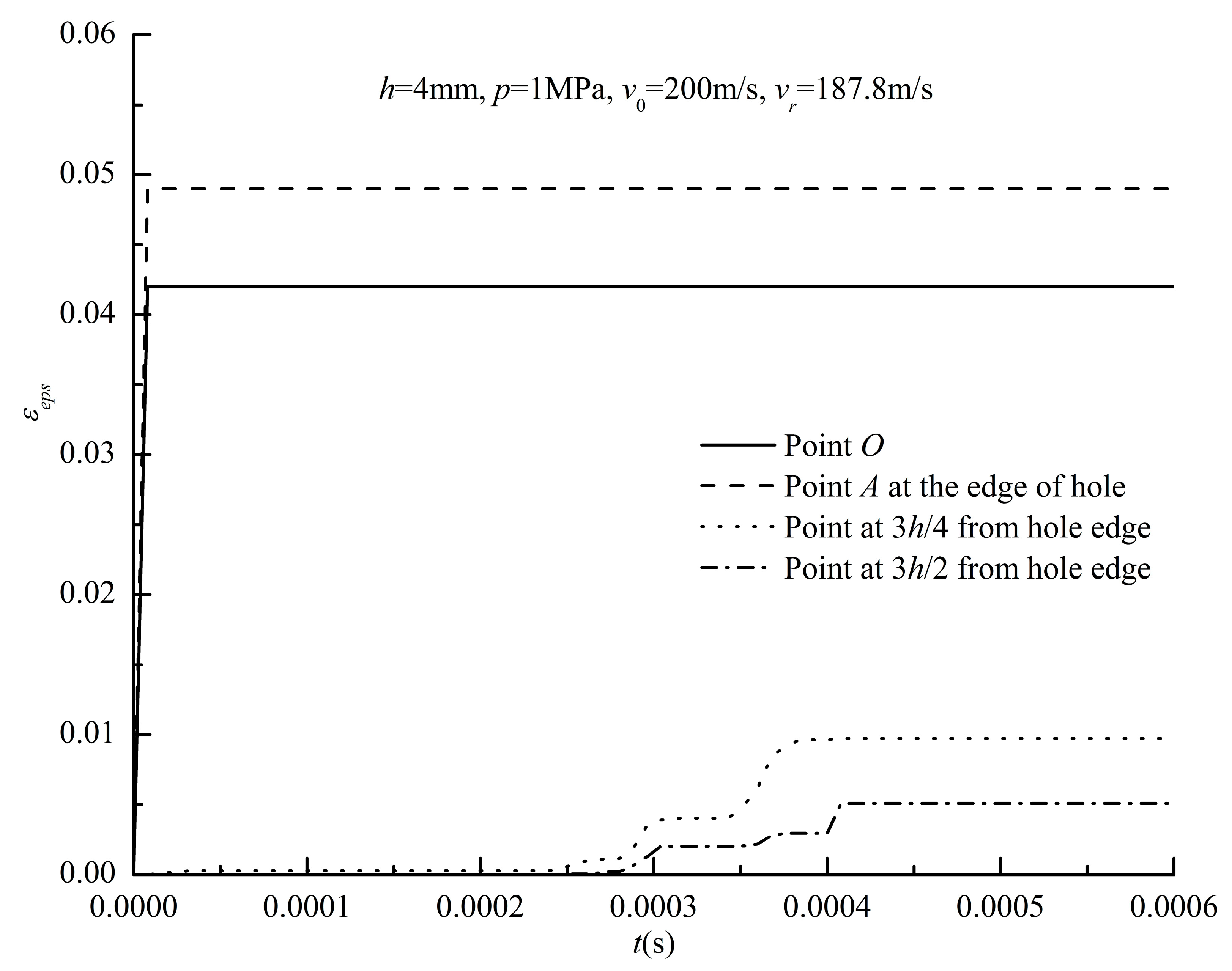
For the structural damage strain caused by bullet impact penetration on the PMMA board,
Figure 13 shows the variation history of the structural plastic strain at different positions during the impact penetration process of the PMMA board with
h=4mm over time. From the figure, it can be seen that the plastic strain caused by tearing damage at the edge of the hole is relatively large, even greater than the plastic strain at the center of the hole that was knocked out as a whole; the plastic strain in the area far from the bullet hole appears later and numerically smaller.
7. Conclusions
In this paper, based on the J-C constitutive and damage model, a finite element calculation model for collision is built, and the parameters of the J-C model are verified by the least square method and the constitutive and damage test data of the specimen materials. The accuracy of the numerical simulation method for collision in this paper is verified by the test of bullet penetrating PMMA plate. At the same time, a simplified model was constructed for the structure under concentrated impact load under external pressure, and the structural characteristic response of PMMA plate under pressure was studied under bullet impact, as well as the variation of residual velocity after bullet impact on the side with structural thickness and applied pressure.
Funding
This research was funded by the National Key R&D Program-Special Deep Sea Key Technology and Equipment ‘ Damage detection and prediction of glass ball cabin’ (grant number 2018YFC0308004), Program of National Natural Science Foundation of China ‘Theoretical and Experimental Research about Structure of Pressure Toroidal Shell in Underwater Engineering’ (grant number 51109190).
Institutional Review Board Statement
“Not applicable” for studies not involving humans or animals.
Informed Consent Statement
“Not applicable.” for studies not involving humans.
Conflicts of Interest
The authors declare no conflict of interest.
References
- Ali, U.; Karim, K.J.B.A.; Buang, N.A. A Review of the Properties and Applications of Poly (Methyl Methacrylate) (PMMA). Polym. Rev. 2015, 55, 678–705. [Google Scholar] [CrossRef]
- Kohnen, W. MTS Manned Underwater Vehicles 2017-2018 Global Industry Overview. Mar. Technol. Soc. J. 2018, 52, 125–151. [Google Scholar] [CrossRef]
- Du, Q.; Hu, Y.; Cui, W. Safety assessment of the acrylic conical frustum viewport structure for a deep-sea manned submersible. Ships Offshore Struct. 2017, 12, S221–S229. [Google Scholar] [CrossRef]
- Q.H. Du, H.G. Q.H. Du, H.G. Jiang and X.K. Hu. Creep behavior analysis of conical observation window for human occupied vehicle based on ABAQUS. Chinese Journal of Ship Research, 2022, 17(1), pp. 108-116. [CrossRef]
- Kemper, B.; Cross, L. Developing “Design by Analysis” Methodology for Windows for Pressure Vessels for Human Occupancy. ASCE-ASME J Risk Uncert Engrg Sys Part B Mech Engrg 2020, 6. [Google Scholar] [CrossRef]
- Du, Q.; Xu, D.; Liu, D. Experimental and numerical analysis on pressure effect of polymethyl methacrylate (PMMA) structure in electric-resistance strain measurement. Ships Offshore Struct. 2021, 1–11. [Google Scholar] [CrossRef]
- Johnson, G.R.; Cook, W.H. Fracture characteristics of three metals subjected to various strains, strain rates, temperatures and pressures. Eng. Fract. Mech. 1985, 21, 31–48. [Google Scholar] [CrossRef]
- P.P. Liu, Y. P.P. Liu, Y. Yin, L.ZH. Chang and Y. Xie. Establishing of Johnson-Cook constitutive equation for normalized steel 50SiMnVB. Ordnance Material Science and Engineering. 2009, 32(1), pp.45-49.
- Z.T. Guo, B. Z.T. Guo, B.Gao, Zh. Guo, W. Zhang. Dynamic constitutive relation based on J-C model of Q235 steel. Explosion and Shock Waves. 2018, 38(4), pp. 804-810.
- P. Yu, X. H. P. Yu, X. H. Yao, Q. Han, Sh.G. Zhang and Zh.Q. Li. Dynamic constitutive model of PMMA at room temperature. Explosion and Shock Waves. 2013, 33(S1), pp. 88-91.
- H.Q. Yao, P.Y. H.Q. Yao, P.Y. Yang, X. Liu and J. Qu. Compression mechanical properties of PMMA under room temperature at low and high strain rates. Earthquake Engineering and Engineering Dynamics. 2019, 39(6), pp. 91-96.
- Z.Y. Wang, Y.Q. Z.Y. Wang, Y.Q. Wang, X.X. Du, T.X. Zhang and H.X. Yuan. Quasi-static tensile test of thick acrylic sheets at different temperatures. Journal of Southeast University (Natural Science Edition). 2018, 48(1), pp. 132-137.
- Moy, P.; Gunnarsson, C.A.; Weerasooriya, T.; Chen, W. Stress-Strain Response of PMMA as a Function of Strain-Rate and Temperature. 2011, 125–133. [CrossRef]
- Kazarinov, N.; Bratov, V.; Morozov, N.; Petrov, Y.; Balandin, V.; Iqbal, M.; Gupta, N. Experimental and numerical analysis of PMMA impact fracture. Int. J. Impact Eng. 2020, 143, 103597. [Google Scholar] [CrossRef]
- H.Y. Wu, G. H.Y. Wu, G. Ma, Y.M. Xia. Experimental study on mechanical properties of PMMA under unidirectional tensile at low and intermediate strain rates. International Journal of Impact Engineering, 2005, 20(2), pp. 193-199.
- Z.T. Guo, B. Z.T. Guo, B. Gao, Zh. Guo, W. Zhang. Investigation on the J-C ductile fracture parameters of 45 steel. Explosion and Shock Waves. 2007, 27(2), pp. 131-135.
- G.W. Zeng, H.X. G.W. Zeng, H.X. Liu, G.J. Shen, L. Wu. Experimental research on viscoelastic damage constitutive model of PMMA. Journal of Materials Science & Engineering. 2019, 37(5), pp. 801-805. [CrossRef]
- Dar, U.A. NUMERICAL CHARACTERIZATION OF ACRYLIC POLYMER UNDER QUASI-STATIC AND DYNAMIC LOADING BY IMPLEMENTING VISCOELASTIC MATERIAL MODEL. Compos. Mech. Comput. Appl. Int. J. 2014, 5, 195–205. [Google Scholar] [CrossRef]
- Gao, Z.Z.; Liu, Z.Q.; Liu, W.; Yue, Z.F. Experimental and Constitutive Investigation on Tensile and Compressive Behavior of MDYB-3 at Different Temperatures and Loading Rates. Int. J. Polym. Mater. Polym. Biomater. 2011, 60, 340–350. [Google Scholar] [CrossRef]
- 20. F. Wang. Study of finite element method and application for high velocity impact. Ph.D. Dissertation, of Thesis, University of Science and Technology of China. May, 2007.
|
Disclaimer/Publisher’s Note: The statements, opinions and data contained in all publications are solely those of the individual author(s) and contributor(s) and not of MDPI and/or the editor(s). MDPI and/or the editor(s) disclaim responsibility for any injury to people or property resulting from any ideas, methods, instructions or products referred to in the content. |
© 2023 by the authors. Licensee MDPI, Basel, Switzerland. This article is an open access article distributed under the terms and conditions of the Creative Commons Attribution (CC BY) license (https://creativecommons.org/licenses/by/4.0/).
