I. Introduction
The permanent magnet rotor machines (PMRMs) have the advantage of high power density and efficiency, and they can be classified into permanent magnet synchronous motor (PMSM) and permanent magnet brushless DC motor (PM BLDC), and the single rotor or dual rotor machine [1-3]. But the reliability of it is not so high, due to the complex rotor structure, especially in the high-speed driven system. Also the rotor magnet has the risk of demagnetization on the condition of very high temperature rising cause by eddy-current losses.
The homopolar inductor alternator (HIA) has a very simple rotor, and it has the advantage of high power density and reliability, and was successfully used in the field of high power-density pulsed power supply [4-8], flywheel energy storage [9-12], airborne applications [
13], propulsion system of ship [
14] and so on.
The HIA can be classified into copper conductor excited HIA [4-9, 15-17], high-temperature superconductor excited HIA [13-14] and permanent magnet (PM) excited HIA [10-12] according to the exciting modes. For the PM excited HIA, because the magnet is placed between the two half shells, the magnetic flux density is almost invariable, the eddy currents losses are very small, what’s more the heat dissipation condition for magnet is much better than the PMRM, so the temperature rise of magnet for PM excited HIA is very low, and there is no risk of magnet demagnetization. So the PM excited HIA has much higher reliability than the PMRM.
For the high-speed HIA with slot stator core, the squeezing effects of winding are extremely serious, and the fundamental air-gap magnetic flux density is relative lower than PMRMs. In this paper, we propose a PM excited HIA with air-gap winding, which has much lower winding copper losses compared with conventional PM excited HIA. And also the air-gap magnetic flux density is very high which can address the issue of relative low fundamental air-gap magnetic flux density for HIA with slot stator core. And in order to enlarge the power capacity, the multistage stator-cores HIAs proposed in [15-17] are adopted. The optimal design of PM excited HIA has been studied in [10-12], but there are no literatures discussing about the optimization of unit number of HIA for the minimum mass of this machine.
The structure of this paper is as follows. First, a brief introduction for the structure of the PM excited HIA with air-gap winding is presented. Then the optimization method for the minimum mass is proposed.
Finally, a 1 MW at 22000 rpm PM excited HIA is designed. The analytical results are verified by the FEM simulations, and the losses, temperature rise, rotor stress and modal of the PM excited HIA are analyzed by simulation. Finally, the comparison between PM excited HIA and PMRM is discussed.
II. Structure of PM excited HIA with air-gap winding
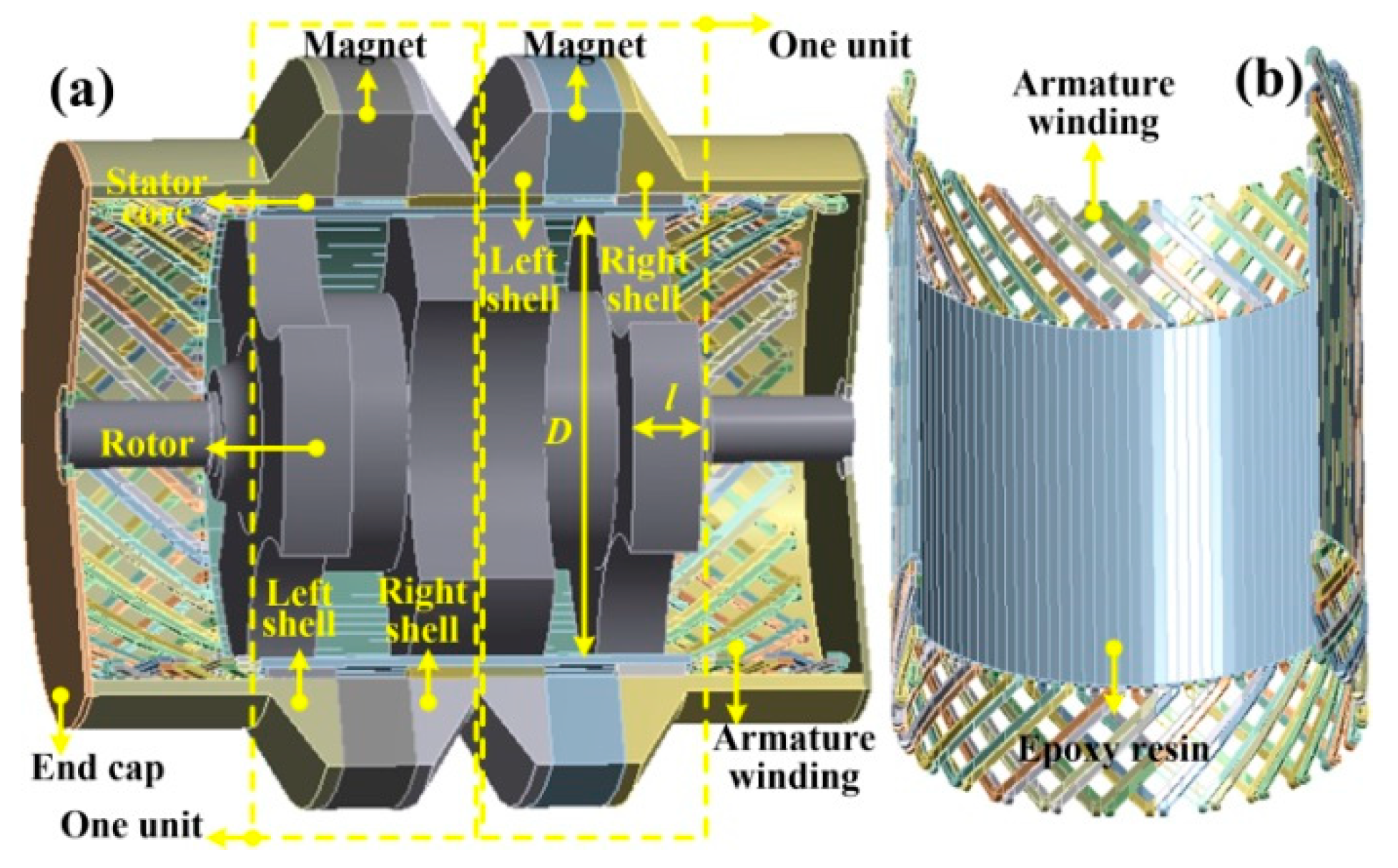
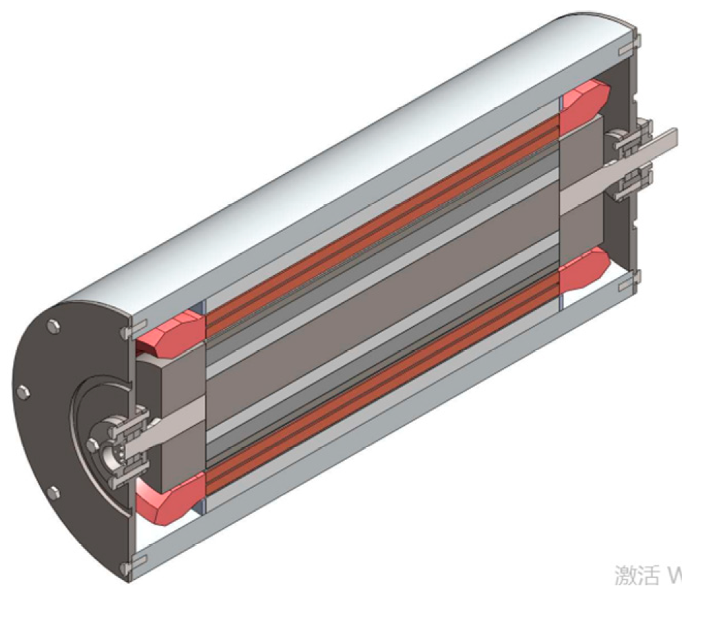
The structure of conventional PM excited HIA can be found in [11-12], and the permanent magnet is placed between the left shell and right shell as shown in
Figure 1 (a). And in this paper, the air-gap winding is adopted. The winding supporting structure is shown in
Figure 1 (b). The windings are placed in the hole of a cylinder which is made from epoxy resin. The epoxy resin cylinder is fixed on the inner surface of the stator core. The single-layer windings are chosen for the PM excited HIA.
III. Calculation of mass
A. The main dimensions
The rotor diameter is determined by:
vcr is the tip speed of rotor,
nr is the rotating speed. The RMS value of no-load phase induced voltage can be calculated by:
Po is the output power, and Iph is the RMS value of phase current, cosϕ is the power factor of machine.
The amplitude of no-load flux per pole for one unit of HIA can be calculated by:
Kmu is the unit number of HIA, Kn1 is the winding coefficient, N is number of series turns per phase, and f is the electrical frequency of machine.
Then the length of one stator core can be calculated by:
Here, p is pole pair number, δ is the air-gap length, and Bδ is maximum value of air-gap magnetic flux density, λ*1 is the per-unit value of fundamental air-gap permeance.
B. The mass of permanent magnet
In the derivation of the dimension parameters of the permanent magnet, the leakage fluxes of magnetic path are also been taken into consideration, which are ignored in [10-12].
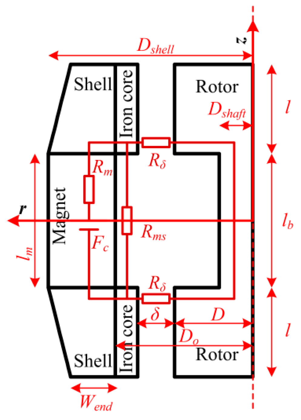
The magnetic circuit is shown in
Figure 2. Here,
Fc is the magneto motive force produced by the permanent magnet,
Rm is the magnetic reluctance of permanent magnet, and
Rms and
Rδ are the magnetic reluctance of leakage and main magnetic path respectively. From the magnetic circuit, the formulas of length of magnet can be obtained that, to be:
The derivation of lm and the definitions of symbols in (5) are presented in appendix A. And the length of magnet lm is the same as the length of rotor shaft lb.
In order to make the value of
lm to be positive, the value of
Ashell must satisfy that:
The mass of permanent magnet can be calculated by:
Here, ρPM is the mass density of permanent magnet.
C. The total mass of machine
The diameter of rotor shaft is:
Here, the Bshaft is the average value of magnetic flux density in rotor shaft.
Then, the mass of rotor can be calculated as follows.
Here, the Kh is defined as ratio of rotor slot depth to air-gap length, and ρr is the mass density of alloy steel.
The mass of armature winding can be calculated by:
Here, m is the phase number of winding, Scu is cross-section area of conductors, ρcu is the mass density of the copper. The calculation of length of armature winding lcoil for one turn is presented in appendix B.
The total mass of machine can be calculated by:
Msta is the mass of stator, Mshell is the mass of shell, and Mo is the mass of other parts, such as end cap, bearings and so on. The calculations of Msta, Mshell are presented in appendix C.
V. Design results
The designed parameters of PM excited HIA are shown in table III. The analytical calculated parameters of electromagnetic properties are shown in table IV, and the air-gap permeance used in the analytical methods is obtained by look-up table. The look-up table is obtained by the two-dimensional FEM simulation model which is presented in [18-19].
TABLE III.
DESIGNED PARAMETERS OF PM EXCITED HIA.
TABLE III.
DESIGNED PARAMETERS OF PM EXCITED HIA.
| Symbol |
Parameter |
Value |
| D |
Rotor diameter (mm) |
304 |
| p |
Pole pair number |
3 |
| h |
Rotor slot depth (mm) |
68 |
| l |
Length of one stator core (mm) |
41 |
| lb
|
Length of shaft |
44 |
| δ |
Air-gap length (mm) |
6 |
| Di
|
Stator-core inner diameter (mm) |
316 |
| Do
|
Stator-core outer diameter (mm) |
332 |
| z1
|
Stator slot number |
54 |
| Lm
|
Length of permanent magnet (mm) |
44 |
| Dshell
|
Shell maximum outer diameter (mm) |
450 |
| a |
Parallel branches |
1 |
| q |
Stator slot number per pole per phase |
3 |
| Nl
|
Winding layers |
1 |
| nc
|
Number of conductors per slot |
1 |
| N |
Number of series turns per phase |
9 |
| β |
Short pitch coefficient of armature winding |
1 |
| Bδ
|
Maximum air-gap magnetic field (T) |
1.5 |
| nr
|
Rotating speed (rpm) |
0-22000 |
| Kmu
|
Unit number of HIA |
2 |
TABLE IV.
PARAMETERS OF ELECTROMAGNETIC PROPERTIES OF PM EXCITED HIA.
TABLE IV.
PARAMETERS OF ELECTROMAGNETIC PROPERTIES OF PM EXCITED HIA.
| Symbol |
Parameter |
Value |
| Erms
|
RMS value of phase EMF (V) |
560 |
| fmax
|
Maximum fundamental electrical frequency (Hz) |
1100 |
| In
|
RMS value of rated phase current (A) |
625 |
| Pn
|
Rated output power (kW) |
1000 |
A. The calculation of electromagnetic parameter
The calculations of RMS value of phase no-load back electromotive force (EMF) for PM excited HIA are like the conventional machine. The calculations of synchronous inductance of
dq axis for PM excited HIA can consult the salient pole synchronous machine, the detailed derivation can be found in reference [
19]. The analytical calculation is presented Table V. And the three-dimensional FEM simulations are used to verify the calculation. The simulation conditions are as follows:
- 1)
For d axis: When the axis of A phase align with d axis, the currents in three phase windings are as follows:
- 2)
For q axis: When the axis of A phase align with d axis, the currents in the three phase windings are as follows:
The simulation has considered the saturation of magnetic circuit, and the winding current of
A phase is the rated value. The synchronous reactance of
dq axis is calculated by the ratio of EMF and current of
A phase, and the synchronous inductance can be calculated from the synchronous reactance. The comparisons of analytical calculation and FEM simulation for synchronous inductances are presented in table V. The analytical results coincide with the FEM simulation results.
TABLE V.
COMPARISONS OF ANALYTICAL CALCULATION AND FEM SIMULATION FOR SYNCHRONOUS REACTANCE.
TABLE V.
COMPARISONS OF ANALYTICAL CALCULATION AND FEM SIMULATION FOR SYNCHRONOUS REACTANCE.
| Parameters |
Analytical |
FEM simulation |
| Synchronous inductance of d axis Ld (uH) |
44 |
44 |
| Synchronous inductance of q axis Lq (uH) |
57 |
60 |
VI. Simulation results
A. The no-load simulation results
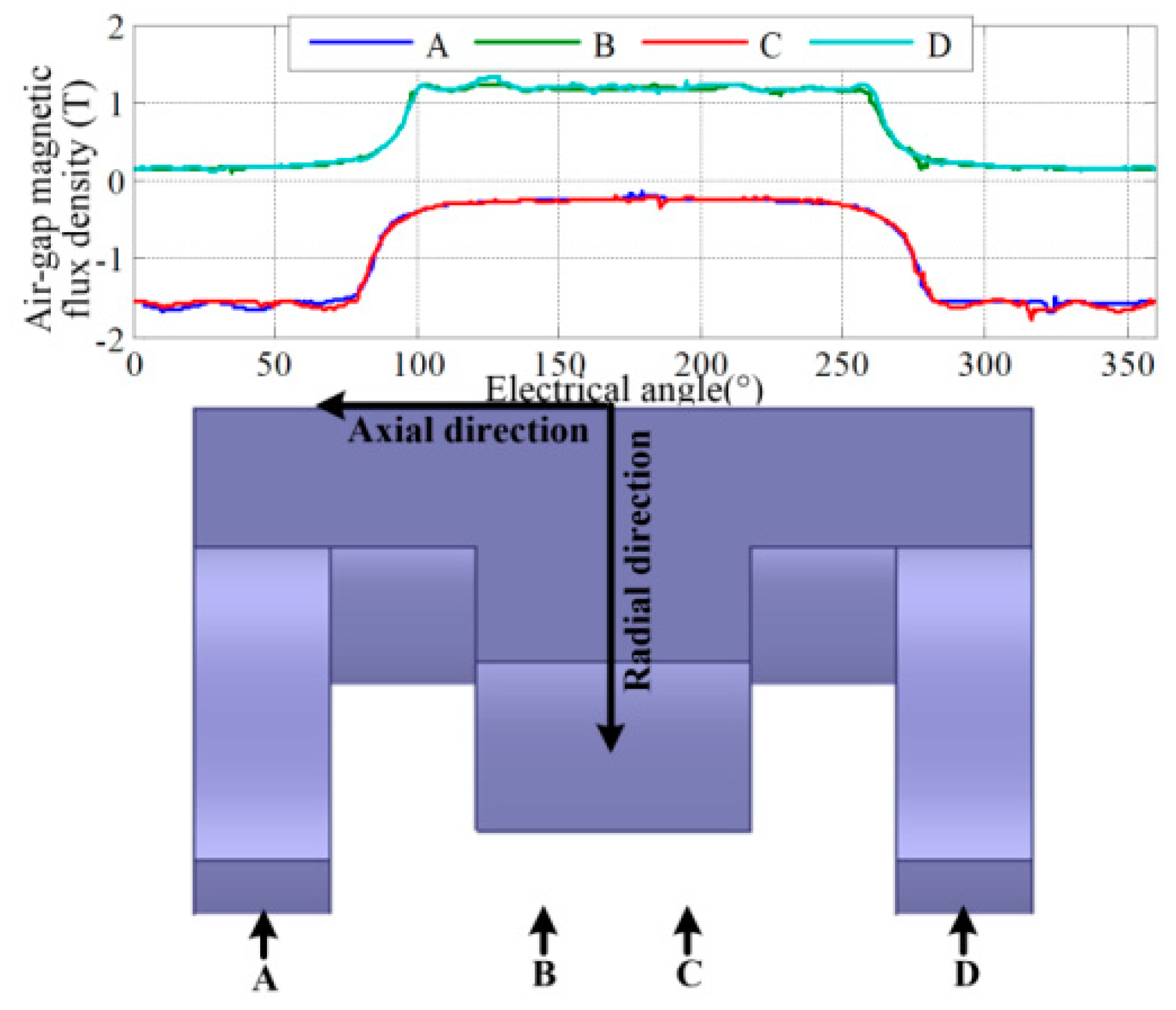
The 3D FEM simulations are used to verify the calculation results in analytical methods. The air-gap magnetic induction distribution is shown in
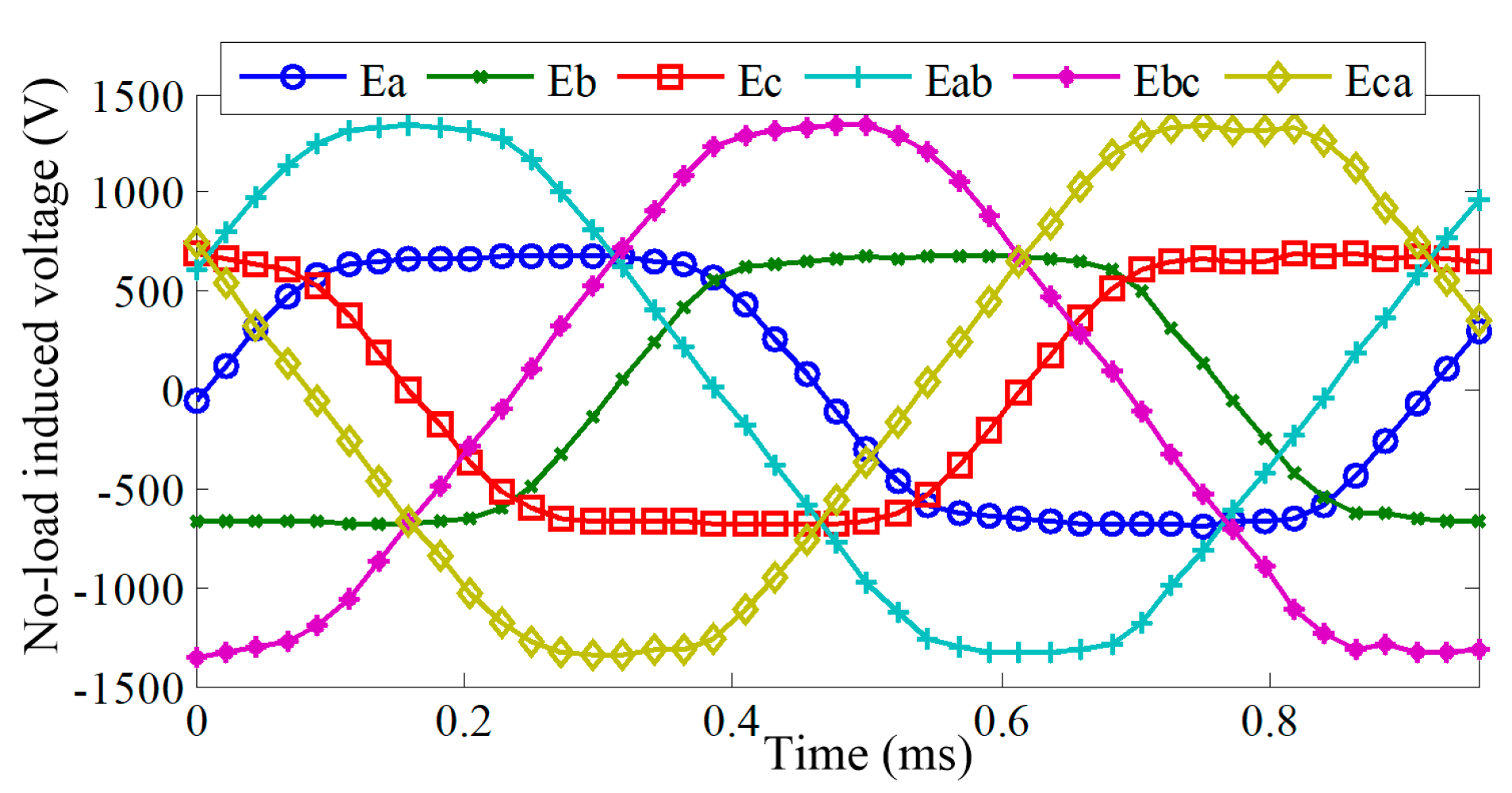
Figure 5, and the maximum value is about 1.5 T. The simulated waveforms of induced no-load phase voltage and line-to-line voltage are shown in
Figure 6, and the RMS value of phase induced voltage is 565 V. The simulation results are coincided with the analytical calculation results.
B. The simulation results at rated load
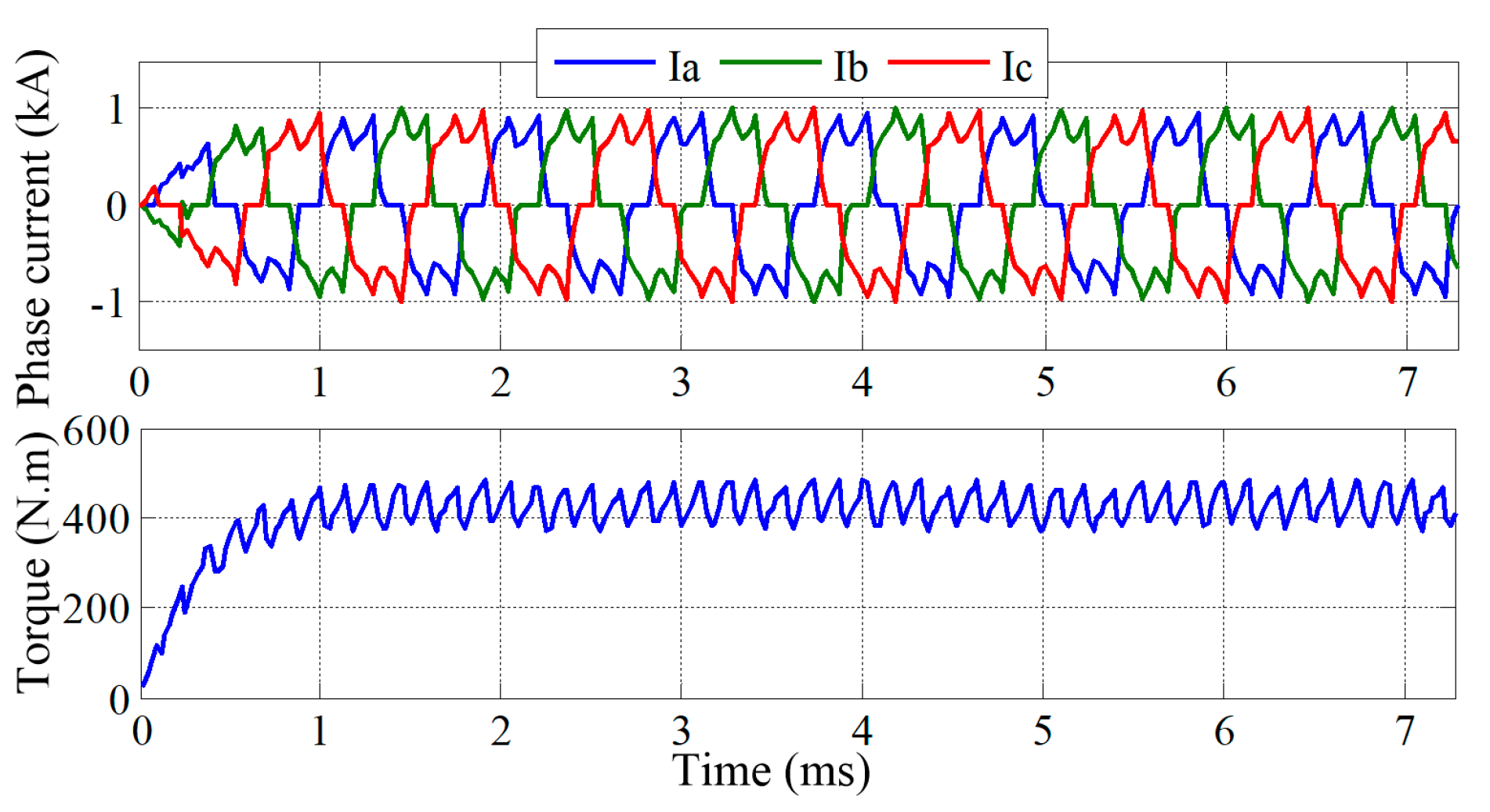
A 3D FEM model combined with external circuit is used to verify the performance at rated load condition. For the external circuit, the square wave control is adopted. The simulated phase current and the torque waveforms are presented in
Figure 7. The simulation results show that the RMS values of phase currents are about 630 A and the average torque is about 434 N. m, which are coincided with the analytical calculation results.
C. Losses and efficiency
The losses of electrical machine are composed of air friction and mechanical losses, iron core losses, rotor eddy-current losses and armature winding copper losses. The air friction losses are calculated by empirical formulas in [
7], and it is verified by the experiment result. The iron losses are calculated by the FEM simulations.
The different kinds of losses for PM excited HIA at rated load are shown in table VI.
TABLE VI.
DIFFERENT KINDS OF LOSSES FOR PM EXCITED HIA AND PMRM AT RATED LOAD.
TABLE VI.
DIFFERENT KINDS OF LOSSES FOR PM EXCITED HIA AND PMRM AT RATED LOAD.
| |
PM excited HIA |
PMRM |
| Winding copper losses (kW) |
5 |
10.4 |
| Stator iron losses (kW) |
2.5 |
14.2 |
| Rotor eddy-current losses (kW) |
6 |
0.35 |
| Mechanical and air friction losses (kW) |
6.4 |
1.7 |
| Total losses (kW) |
19.9 |
26.65 |
| Efficiency |
98% |
97.4% |
For the PM excited HIA, due to the slotless stator core structure, the extremely serious squeezing effects of armature winding are relieved, so the armature winding copper losses of PM excited HIA are much less than the conventional PM excited HIA.
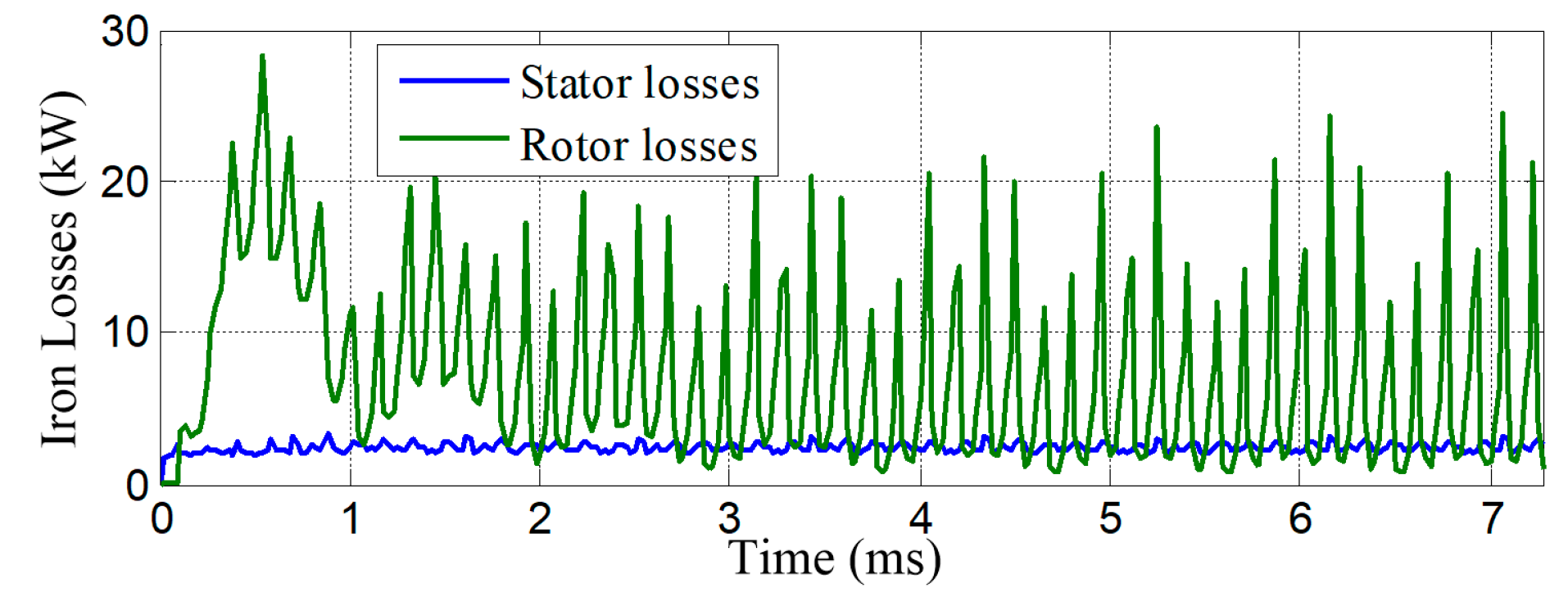
The simulated results of iron losses for PM excited HIA are shown in table VI and
Figure 8. It can be found that the rotor and stator iron losses are 6 kW and 2.5 kW, respectively.
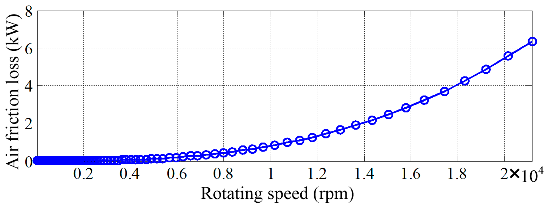
In order to reduce the air friction losses, pumping vacuum is used. The vacuum degree is set to be 0.95, considering the difficulty of pumping vacuum and rotating seal. The calculated air friction losses for the PM excited HIA are presented in
Figure 9. And at 22000 rpm, the air friction losses are about 6.3 kW.
D. Temperature rising
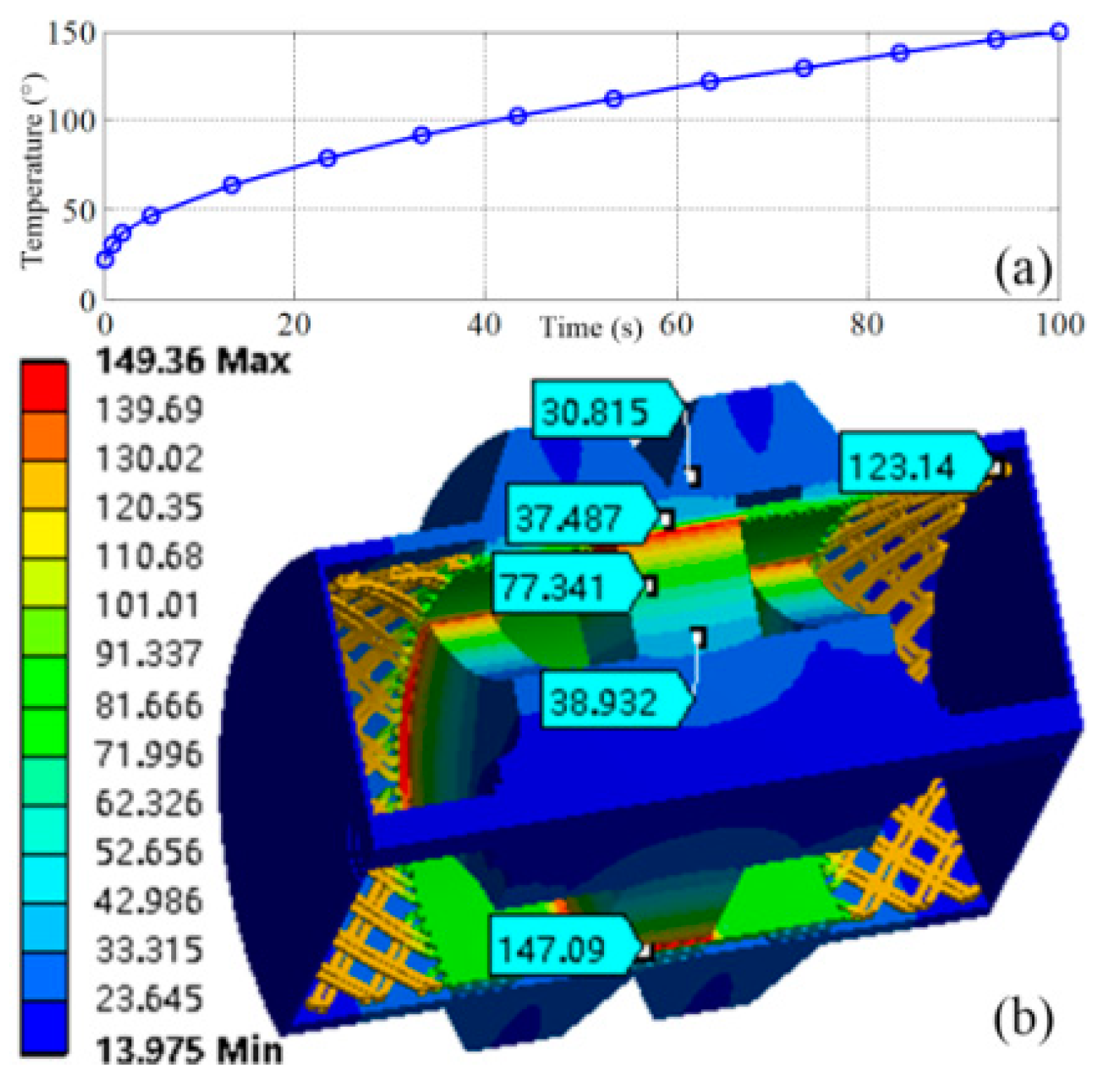
The temperature rising is simulated by the 3D FEM simulation. The temperature rising curve is shown in
Figure 10 (a), and at 100 s, the 3D temperature distribution is shown in. The maximum temperature is 149.39 ℃, which is at the face of rotor, and maximum temperature for armature winding is 123 ℃, which is at the end of the winding. So, the machine can operate safely.
E. Rotor stress and modal
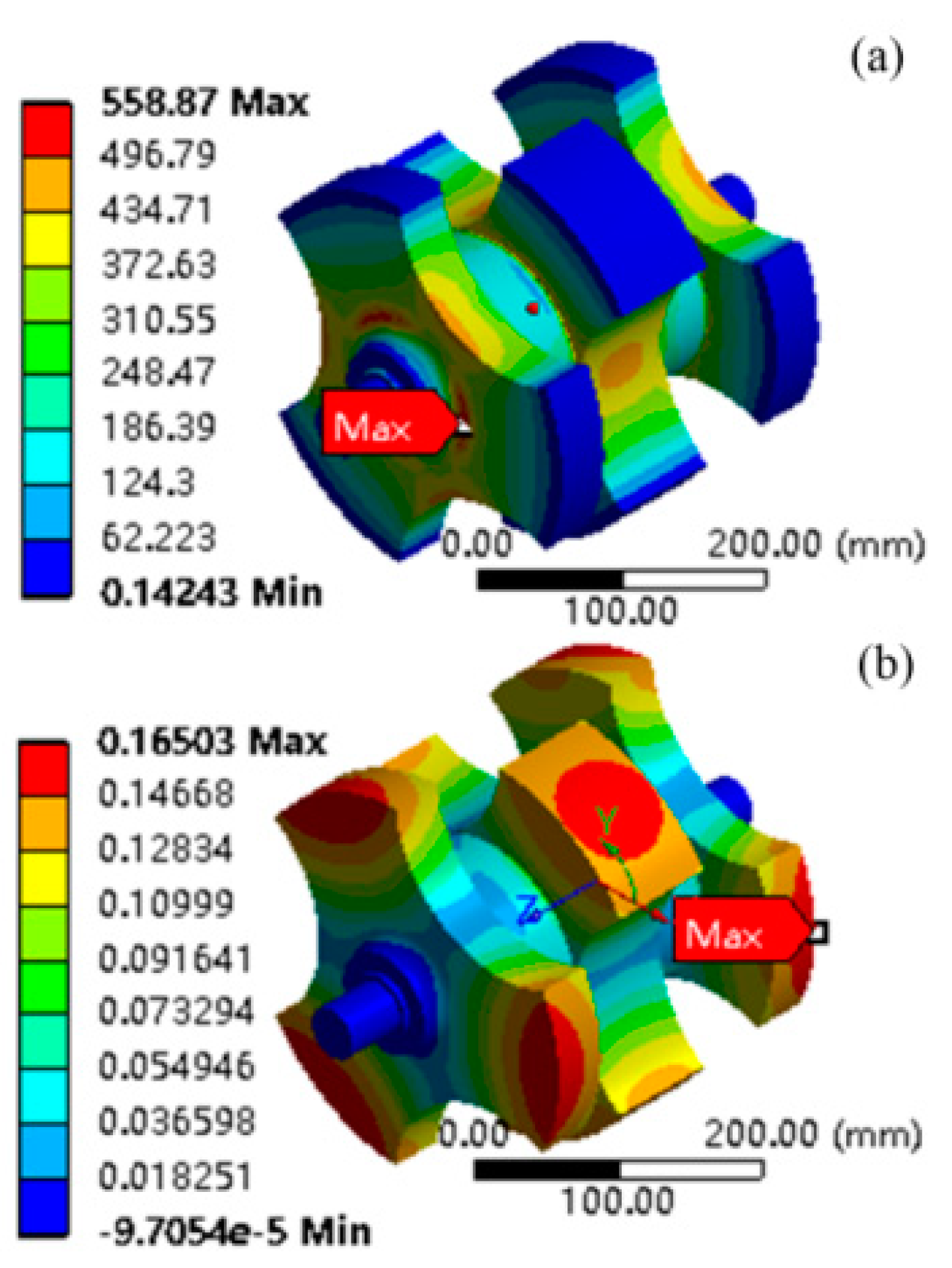
The rotor stress and rotor modal are simulated by the 3D FEM simulation. The von misses stress of rotor is shown in
Figure 11 (a), and the radial deformation is shown in
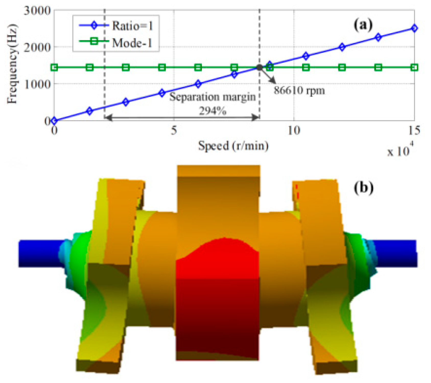
Figure 11 (b). The maximum stress is 558 Mpa which is much less than tensile strength of rotor material. The maximum radial deformation is 0.165 mm, which is much less than physical air-gap length. The first critical speed of the rotor is 86610 rpm, which is much larger than the operation speed 22000 rpm. So the rotor system can safely operate.
VII. Comparisons between PM excited HIA and PMRM
In order to compare the PM excited HIA and the PMRM; the PMRM is designed on the condition that the rotating speed, pole pair number, the stator slot number and the winding pitch are the same with the PM excited HIA. The designed parameters of PMRM are presented in table VII. The stator core of PMRM is slot-core structure. The parallel branches of PMRM winding are 3, while for the PM excited HIA the parallel branches are 1. The conductor per slot for PMRM is 2, while for the PM excited HIA the conductor per slot is 1.
TABLE VII.
DESIGNED PARAMETERS OF PMRM.
TABLE VII.
DESIGNED PARAMETERS OF PMRM.
| Symbol |
Parameter |
Value |
| Dro
|
Rotor outer diameter (mm) |
132 |
| P |
Pole pair number |
3 |
| hM
|
Thickness of magnet (mm) |
20 |
| nMs
|
Number of slices for magnet in axial direction |
20 |
| L |
Length of rotor or stator (mm) |
480 |
| Dri
|
Rotor inner diameter (mm) |
60 |
| δ |
Air-gap length (mm) |
10 |
| Di
|
Stator-core inner diameter (mm) |
152 |
| Do
|
Stator-core outer diameter (mm) |
255 |
| z1
|
Stator slot number |
54 |
| zsk
|
Skew width in slot number |
1 |
| αp
|
Mechanical pole embrace |
0.6 |
| Dshell
|
Shell maximum outer diameter (mm) |
315 |
| a |
Parallel branches |
3 |
| q |
Stator slot number per pole per phase |
3 |
| Nl
|
Winding layers |
2 |
| nc
|
Number of conductors per slot |
2 |
| N |
Number of series turns per phase |
6 |
| β |
Short pitch coefficient of armature winding |
1 |
| Bδ
|
Maximum air-gap magnetic field (T) |
0.7 |
| nr
|
Rotating speed (rpm) |
0-22000 |
The three-dimension model of the PMRM is presented in
Figure 13. It can be seen that, the axial length of PMRM are much large than the PM excited HIA. This is because that, for the PM excited HIA, the rotor tip speed can be very large, while for the PMRM due to the complex rotor structure, the rotor tip speed cannot be too large, and the rotor diameter is small relatively. The comparisons of the PM excited HIA and PMRM are presented in table VIII. It can be seen that, the PM excited HIA has the equivalent power density and larger efficiency compared with the PMRM.
TABLE VIII.
THE COMPARISON OF PMRM AND PM EXCITED HIA.
TABLE VIII.
THE COMPARISON OF PMRM AND PM EXCITED HIA.
| Parameters |
PMRM |
PM excited HIA |
| Maximum rotating speed nmax
|
22000 |
22000 |
| RMS value of phase EMF (V)@ nmax
|
494 |
560 |
| Maximum electrical frequency (Hz) |
1100 |
1100 |
| Synchronous inductance of d axis (uH) |
25.8 |
44 |
| Synchronous inductance of q axis (uH) |
25.8 |
57 |
| Weight of permanent (kg) |
18 |
46 |
| Total weight of machine (kg) |
240 |
240 |
| Rotor initial (kg.m2) |
0.18 |
0.7 |
| Efficiency at rated output power |
97.4% |
98% |
A. The power factor
From table V, it can be found that the synchronous inductance of PMRM is much less than the PM excited HIA. This is because that the air-gap length between rotor and stator iron for PMRM is much larger than PM excited HIA. So, the power factor of PMRM is larger than the PM excited HIA.
B. Losses and Efficiency
The different kinds of losses for PMRM at rated load are shown in table VI. It can be found that, the armature copper losses and iron core losses of PM excited HIA are less than the PMRM, while the rotor eddy-current losses and air friction losses of PM excited HIA are much larger than the PMRM.
- 1)
Winding copper losses
For the PM excited HIA, due to the slotless stator core structure, the extremely serious squeezing effects of armature winding are relieved, so the armature copper losses of PM excited HIA are much less than the PMRM.
- 2)
Iron losses
The iron core losses of PM excited HIA are 2.5 kW, while for the PMRM the iron core losses are 14.2 kW. The reason is that the iron losses are proportional to the square of magnetic flux density, and the stator core of PMRM is slot-core structure, and the magnetic flux density in the tooth is large, while the stator core of PM excited HIA is slot-less, the magnetic flux density is uniform relatively. What’s more, the weight of stator core for PMRM is much larger than the PM excited HIA, which are 80 kg and 15 kg for PMRM and PM excited HIA respectively, and the reason is that the thickness of stator iron yoke for PM excited HIA is much smaller than the PMRM. The magnetic fluxes of PM excited HIA pass the shell and then the other half stator core, so there is no requirement for stator iron yoke to pass the magnetic fluxes between two poles.
- 3)
Rotor eddy-current losses
The rotor eddy-current losses of PMRM are 0.35 kW; while the rotor eddy-current losses of PM excited HIA are 6 kW. The reason is that the magnet segmentation of PMRM in axil direction, which can reduce eddy current dramatically.
- 4)
Air friction losses
The air friction losses of PM excited HIA are much larger than the PMRM. And at the rotating speed of 22000 rpm, the losses are 6.4 kW and 1.2 kW for the PM excited HIA and PMRM respectively. The reason is that the rotor tip speed of PM excited HIA is much larger than the PMRM, and the rotor structure of PM excited HIA is salient while the rotor outer face of PMRM is smooth.
C. The reliability
The rotor structure of PMRM is complex, while the rotor of PM excited HIA is very simple and it has very high reliability. On the other hand, the magnet of PMRM has eddy current losses, and in some worse condition of heat dissipation, the temperature rise of magnet could be very high, and this can cause the magnet loss of magnetism. But, for the PM excited HIA, because the magnet is placed between the two half shells, the magnetic flux density is almost invariable, the eddy currents losses are very small, what’s more the heat dissipation condition for magnet is much better than the PMRM, so the temperature of magnet for PM excited HIA is very low, and there is no risk of magnet demagnetization. So, it can be concluded that the PM excited HIA has much higher reliability than the PMRM.
VIII. Conclusions
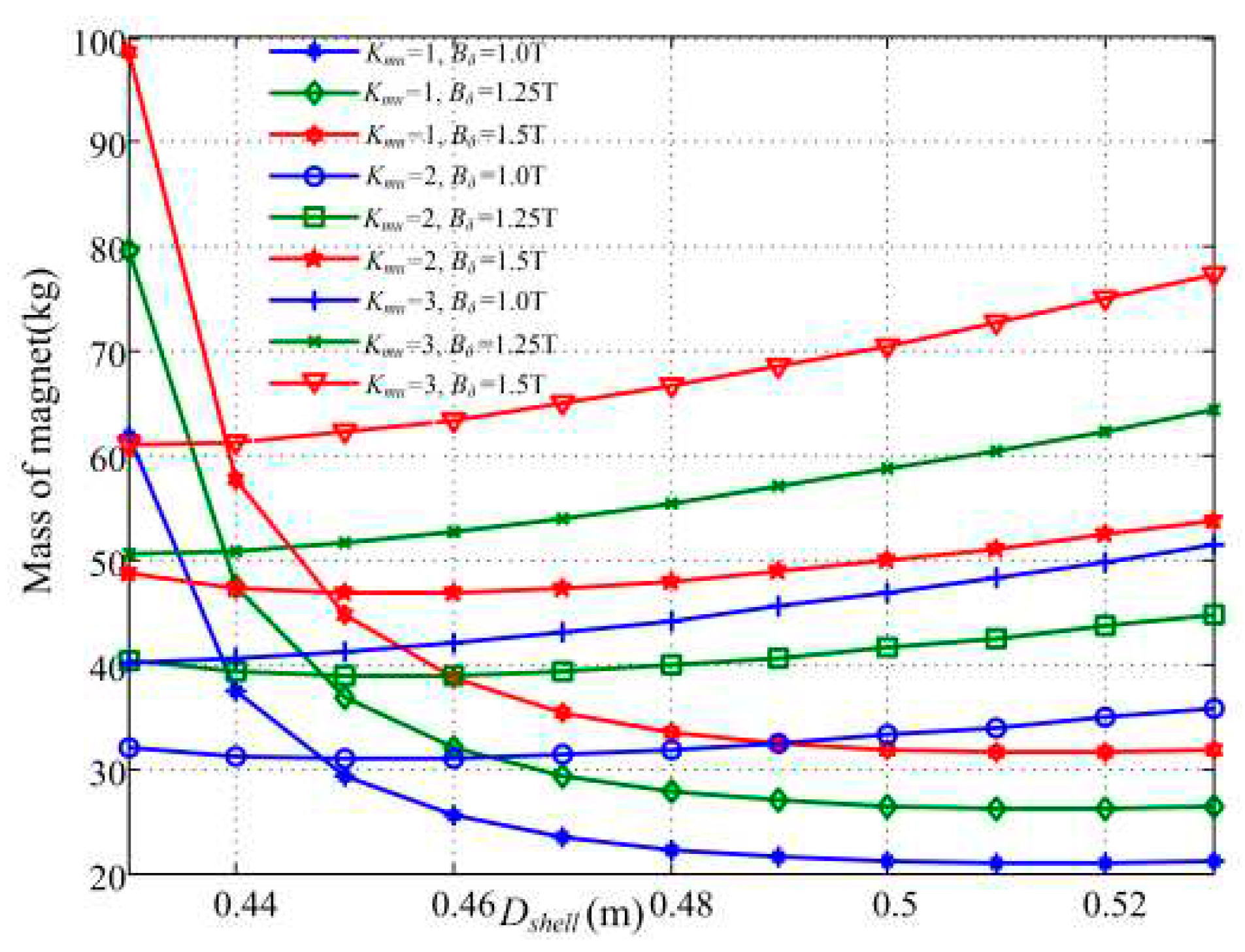
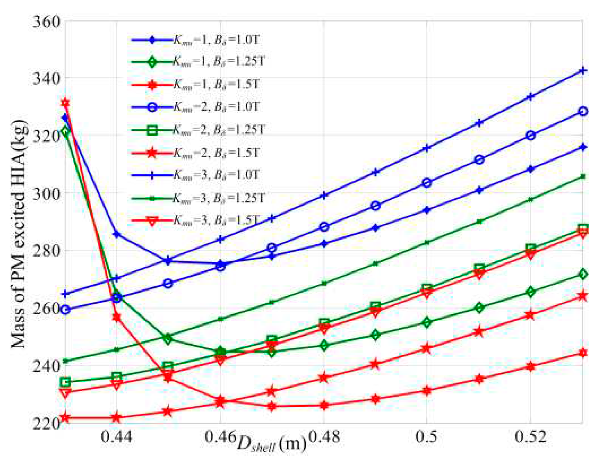
This paper proposes a permanent magnet excited HIA with air-gap winding used for the high-speed driving system. The optimization method for the minimum mass is proposed. The calculation results show that the larger the air-gap magnetic flux density is, the lighter the machine is, but the larger the mass of magnet is. The relationship between the unit number, shell diameter and the mass is studied, and calculation results show that there is an optimal value for shell diameter and unit number to make the mass to be smallest.
A 1 MW at 22000 rpm PM excited HIA is designed. The analytical results are verified by the FEM simulations, and the losses, temperature rise, rotor stress and modal of the PM excited HIA are analyzed by FEM simulation. The FEM simulation results show that the solid rotor eddy-current losses and the temperature rise of PM excited HIA are acceptable. Also the rotor strength is adequate, and the rotor system is a stiffness rotor, and it can safely operate. The PM excited HIA has equal power density and larger efficiency than the PMRM.
The prototype machine is to be made in the future, and the plan of test experiment is ongoing used to examine the theory and design methods of this paper.
IX. Appendix
A. Calculation of length of magnet lm
From the ohm’s law for magnetic circuit, the magneto motive force produced by the permanent magnet is calculated by:
Here,
Fc is the MMF produced by the permanent magnet, and
μ0 is permeability of vacuum.
Bshell is the average flux density in the permanent magnet, and
Ashell is the cross-section area of permanent magnet.
Rm is the magnetic reluctance of permanent magnet, to be:
Here,
μr is the relative permeability of permanent magnet. Substituting (A2) to (A1), it can be obtained that:
The magneto-motive force produced by the permanent magnet is:
Combining (A3) and (A4), it can be obtained that:
The average flux density in the permanent magnet
Bshell can be calculated by:
Here,
λ*
0 is the per-unit value of DC component of air-gap permeance.The cross-section area of permanent magnet
Ashell is:
Here, Dshell is the maximum diameter of shell, which is also equal to the outer diameter of permanent magnet; Do is the outer diameter of stator core.
Φms is the magnetic flux leakage of permanent magnet, and it can be calculated by:
Rms is the magnetic reluctance of leakage magnetic path, and it can be calculated by:
Ams is the cross section area of leakage magnetic path, and it can be calculated by:
Here,
Dshaft is the diameter of rotor shaft. Combining (A6), (A8) and (A9), it can be obtained that:
Combining (A5) and (A11), the length of magnet can be obtained.
B. Calculation of length of armature winding
The calculation of length of the armature winding for one turn is:
Here, len is the length of one-side end windings for one half turn.
C. Calculation of mass
The calculation of mass of stator is:
Here, ρs is the mass density of silicon steel sheet.
The calculation of mass of shell is:
Here, lendp is the axial length of end winding, and l0 is the one-side end extended length of end winding. Wend is the thickness of shell end.
References
- Nicolas Bernard, Rachid Missoum, Linh Dang, Nassim Bekka, Hamid Ben Ahmed, and Mohamed El-Hadi Za¨ım, “Design Methodology for High-Speed Permanent Magnet Synchronous Machines”, IEEE Transactions on Energy Conversion, vol. 31, no. 2, pp.477-485, 2016. [CrossRef]
- Bert Hannon, Peter Sergeant, and Luc Dupré, “2-D Analytical Subdomain Model of a Slotted PMSM With Shielding Cylinder”, IEEE Transactions on Magnetics, vol. 50, no. 7, pp. 8101410, 2014. [CrossRef]
- Zhenyu Jia and Byeongwoo Kim, “Online Trained Neural Network-PI Speed Controller for DTC based IPMSM Drives,” International Journal of Electrical and Electronic Engineering & Telecommunications, Vol. 7, No. 3, pp. 108-113, July 2018. 20 July.
- Zhang’ao Ren, et al., “Investigation of a novel pulse CCPS utilizing inertial energy storage of homopolar inductor alternator,” IEEE Trans. Plasma Sci., vol. 39, no. 1, pp. 310-315, Jan. 2011. [CrossRef]
- Zhang’ao Ren, Kexun Yu, Qingming Xin, Yuan Pan, “Performance of homopolar inductor alternator with diode-bridge rectifier and capacitive load,” IEEE Trans. Ind. Electron., vol. 60, no. 11, pp. 4891–4902, Nov. 2013. [CrossRef]
- Qingming Xin, Kexun Yu, Qilin You, Man Yuan, “Repetition pulse charging characteristics for homopolar inductor alternator with rectified capacitive load,” IEEJ Trans. Elect. Electron. Eng., vol. 10, no. 1, pp. 44–49, 2015. [CrossRef]
- Longjian Liu,Kexun Yu, Xianfei Xie, “Analysis and test efficiency of a high-power pulsed power supply based on HIA”, IEEE Transactions on Plasma Science, vol. 47, no. 5, pp. 2293-2301, 2019. [CrossRef]
- Kexun Yu, Longjian Liu, Xainfei Xie, “Design consideration of eddy current losses for rotor of HIA with rectifier and capacitive loads.” IEEE Trans. Plasma Sci., vol. 46, no. 8, pp. 2949-2953, Aug. 2018. [CrossRef]
- Tsao P, Senesky M, Sanders S R. “An integrated flywheel energy storage system with homopolar inductor motor/generator and high-frequency drive”. IEEE Transactions on Industry Applications, 2003, 39(6): 1710-1725. [CrossRef]
- Z. Q. Liu, K. Wang and F. Li, “Design and Analysis of Permanent Magnet Homopolar Machine for Flywheel Energy Storage System”, IEEE Transactions on Magnetics, vol. 55, no. 7, pp. 8105706, July. 2019. [CrossRef]
- Qing Li, Jiangtao Yang, Shoudao Huang, Ping Liu, Yaojing Feng, and Lei Wang, ”No-Load Electromagnetic Performance Analysis of a Mechanically Modulated Permanent Magnet Homopolar Inductor Machine”, IEEE Transactions on Transportation Electrification, vol. 8, no. 1, pp. 1168-1181, 2022. [CrossRef]
- Jiangtao Yang, Qing Li, Shoudao Huang, Caiyong Ye, Ping Liu, Bo Ma, and Lei Wang, “Design and Analysis of a Novel Permanent Magnet Homopolar Inductor Machine With Mechanical Flux Modulator for Flywheel Energy Storage System”, IEEE Transactions on Industrial Electronics, vol. 69, no. 8, pp. 7744-7755, Aug. 2022. [CrossRef]
- K. Sivasubramaniam, et al., “Development of a high speed HTS generator for airborne applications.” IEEE Trans. Appl. Supercon., vol. 19, no. 3, pp. 1656-1661, Jun. 2009. [CrossRef]
- S.H. Lee, J.P. Hong, Y.K. Kwon, Y.S. Jo, and S.K. Baik, “Study on Homopolar Superconductivity Synchronous Motors for Ship Propulsion Applications”, IEEE Trans. Applied Superconductivity, vol. 18 (2), pp. 717-720, 2008. [CrossRef]
- C. Ye, J. Yang, W. Xu, F. Xiong, and X. Liang, “A novel multi-unit outrotor homopolar inductor machine for flywheel energy storage system,” IEEE Trans. Magn., vol. 54, no. 11, pp. 1–5, Nov. 2018. [CrossRef]
- Jiangtao Yang, Caiyong Ye, Shoudao Huang, “Development and Analysis of an Outer Rotor Homopolar Inductor Machine for Flywheel Energy Storage System”, IEEE Transactions on Industrial Electronics, vol.68, no.8 (2021): 6504 - 6515. [CrossRef]
- Jiangtao Yang, Caiyong Ye, Xin Liang, and Fei Xiong, “Study of a Novel High-Speed Compensated Pulsed Alternator With Multistage Stator Cores”, IEEE Transactions on Plasma Science, 2019, 47(5): 2376-2381. [CrossRef]
- Zhenxiu Lou, et al., “Analysis of homopolar inductor alternator for high reliability high power density applications,” in Proc. IEEE 6th Int. Power Electron. Motion Control Conf., 09, pp. 841–844. [CrossRef]
- Z. Lou, et al., “Analytical calculation of synchronous reactances of homopolar inductor alternator,” IEEE Trans. Plasma Sci., vol. 43, no. 5, pp. 1462-1468, May. 2015. [CrossRef]
|
Disclaimer/Publisher’s Note: The statements, opinions and data contained in all publications are solely those of the individual author(s) and contributor(s) and not of MDPI and/or the editor(s). MDPI and/or the editor(s) disclaim responsibility for any injury to people or property resulting from any ideas, methods, instructions or products referred to in the content. |
© 2023 by the authors. Licensee MDPI, Basel, Switzerland. This article is an open access article distributed under the terms and conditions of the Creative Commons Attribution (CC BY) license (http://creativecommons.org/licenses/by/4.0/).
