Submitted:
07 July 2023
Posted:
10 July 2023
You are already at the latest version
Abstract
Keywords:
1. Introduction
2. Experimental details
2.1. Substrates
2.2. Coating deposition technique
2.3. Characterizations
3. Results and discussion
3.1. Chemical composition and microstructure of layers
3.1.1. EDS analysis of the CrAlN layers
3.1.2. Morphology of the CrAlN layers
3.1.3. XRD analyses of the CrAlN layers
3.2. Mechanical properties and corrosion
3.2.1. Internal stresses of the CrAlN layers
3.2.2. Hardness, Young’s modulus, friction coefficient and wear of the CrAlN films
3.2.2.1. Hardness, Young’s modulus of the CrAlN films
3.2.2.2. Adhesion strength prediction of CrAlN coatings
3.2.2.3. Friction coefficient of the CrAlN films
3.2.2.4. The wear mechanism of CrAlN films
3.2.3. Electrochemical tests
4. Conclusions
- a)
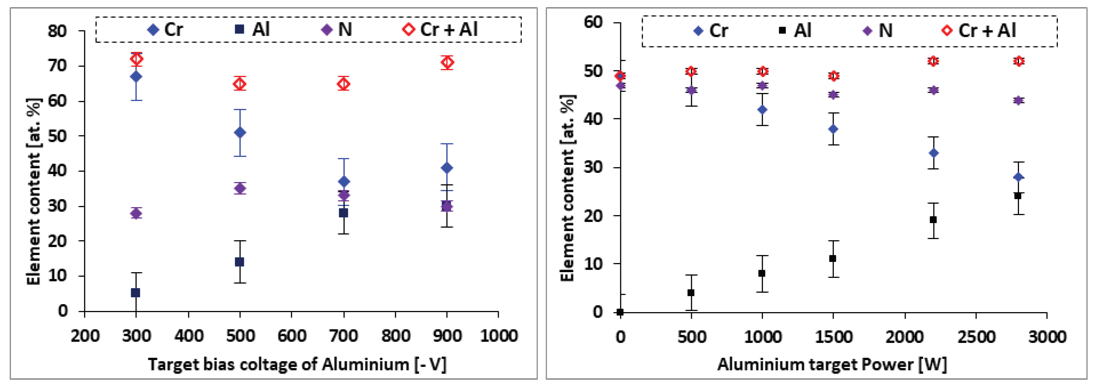
- EDS analyses confirm that the structure of the CrAlN layers is a solid solution allowing the substitution of Cr atoms by Al atoms, showing that the sensitivity constant is more stabilized on CrAlNR films than on CrAlNS, reflecting the impact of the substrate’s rotational mode on film homogeneity.
- b)
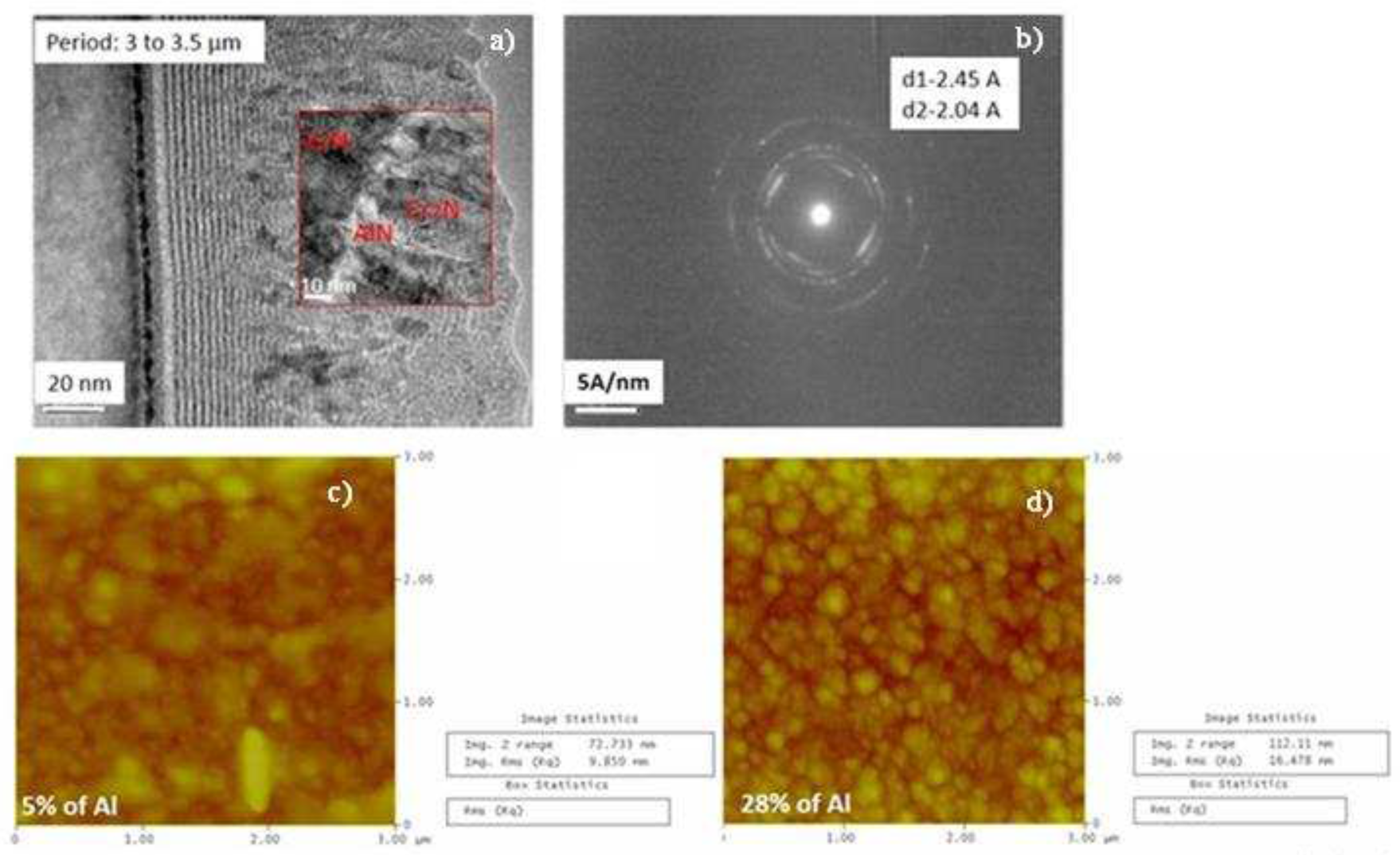
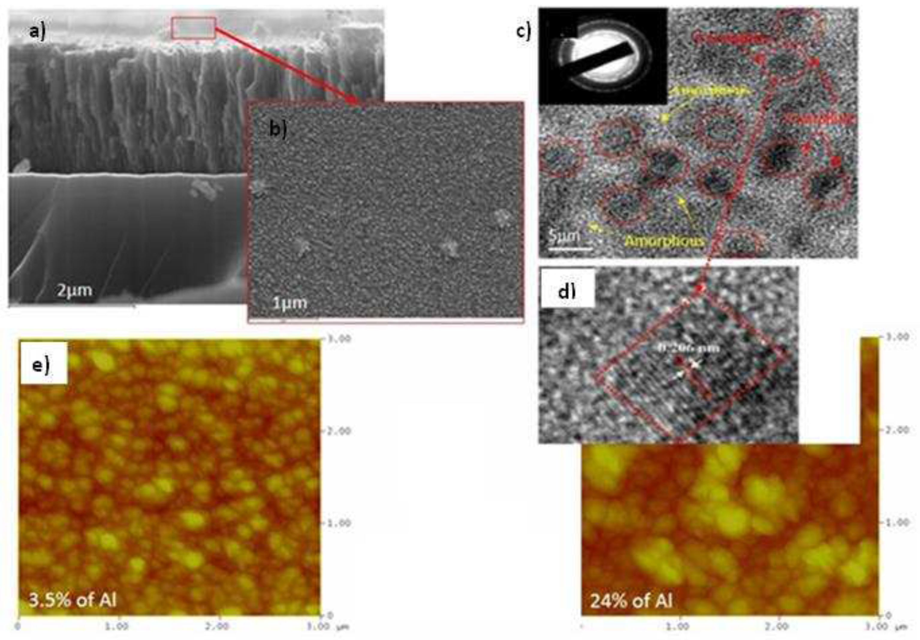
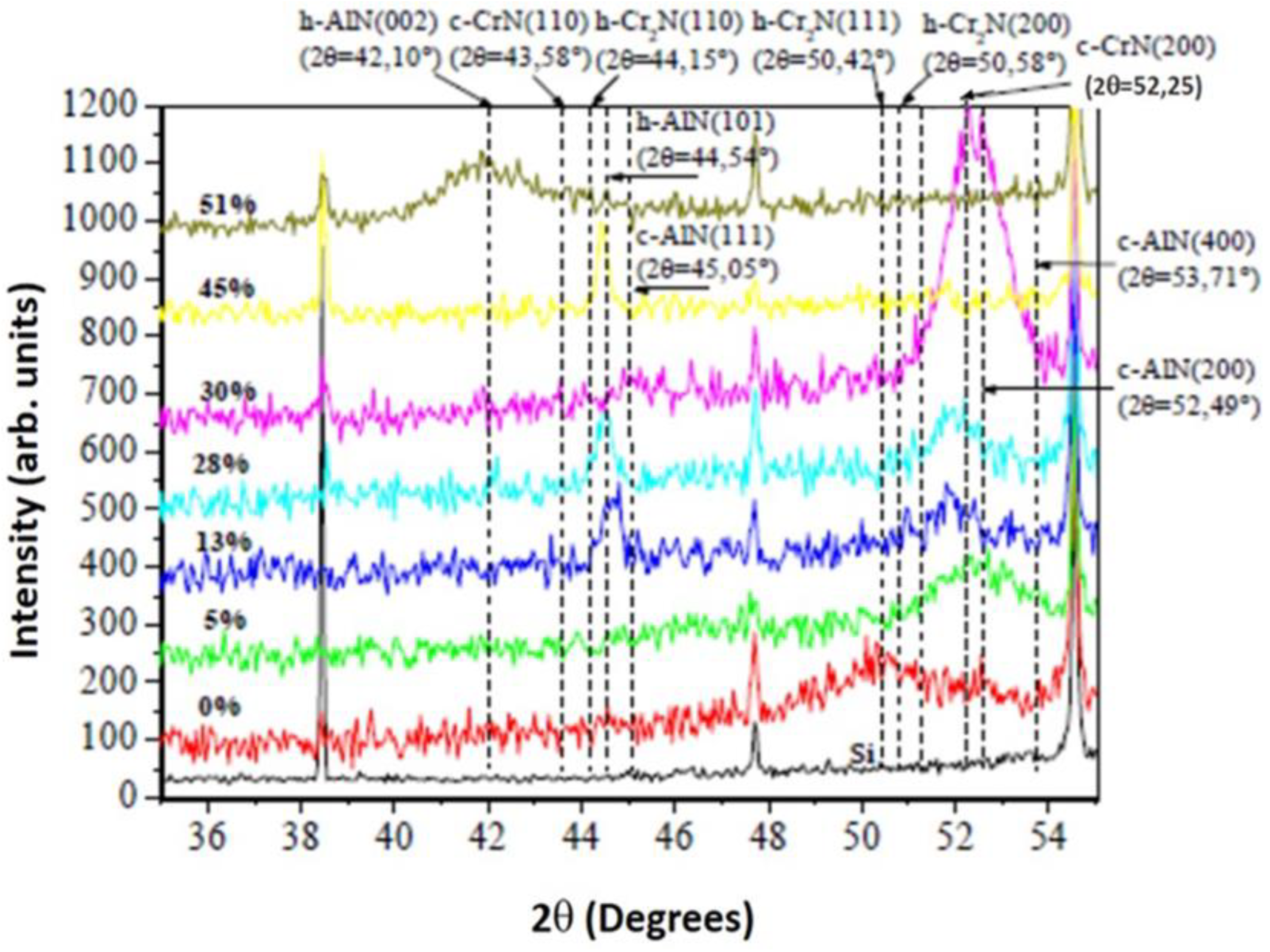
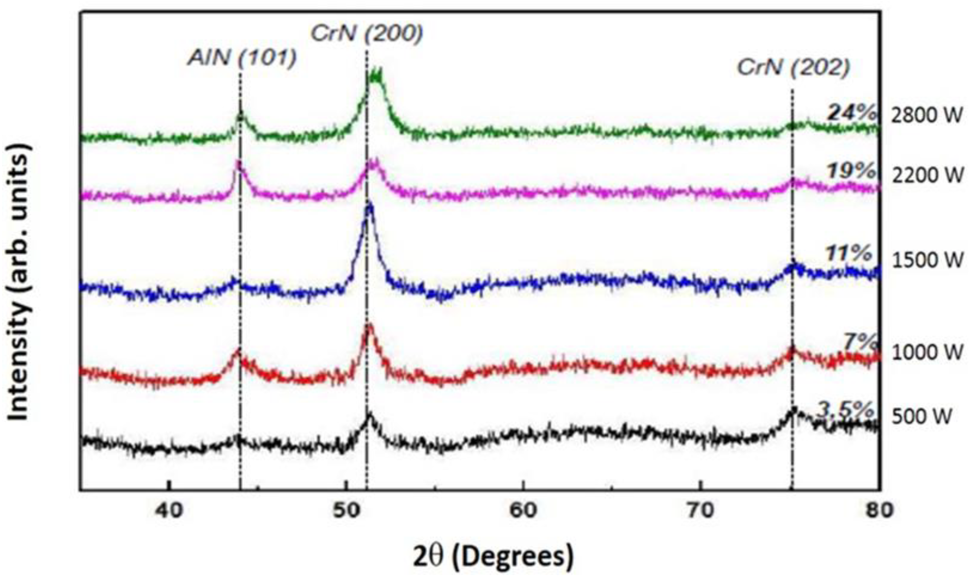
- Both CrAlNS and CrAlNR films are well crystallized at low aluminum content. At higher aluminum contents, CrAlNS films become amorphous. In addition, the CrAlNR coating is composed of two phases (CrN and AlN) for the rotating substrate and three phases (Cr2N, CrN and AlN) for the stationary substrate.
- c)
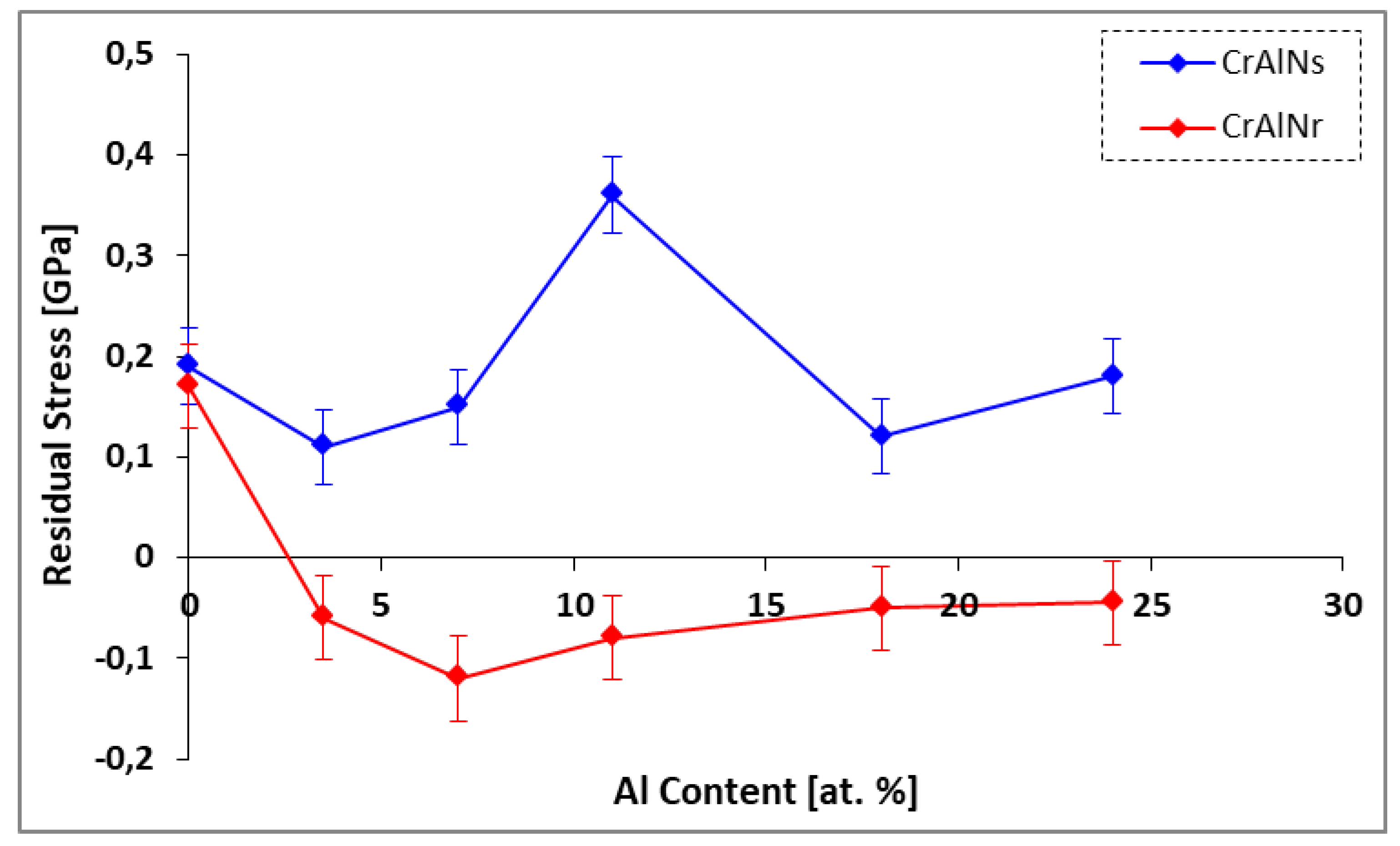
- CrAlNS coatings exhibit tensile stresses, while CrAlNR has generated residual compressive stresses. Indeed, substrate rotation generates relaxation of internal coating stresses (defects, high target ionization rate), also accompanied by low density.
- d)
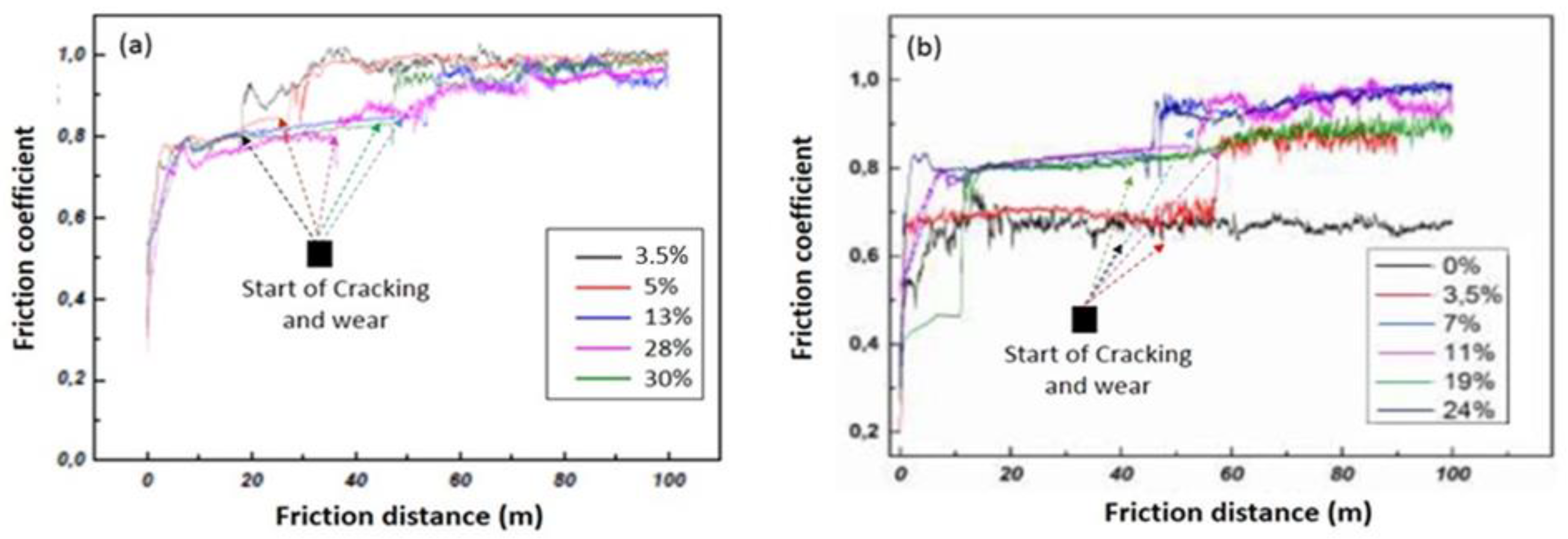
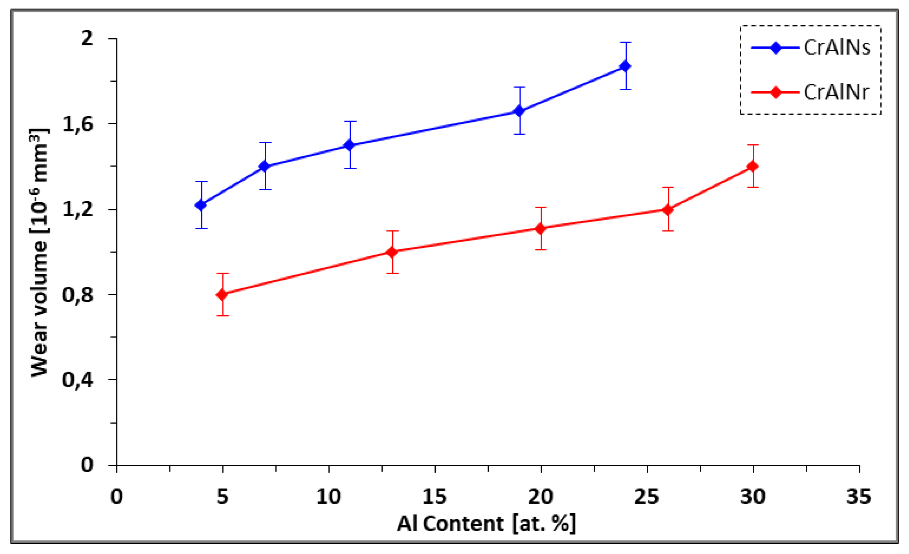
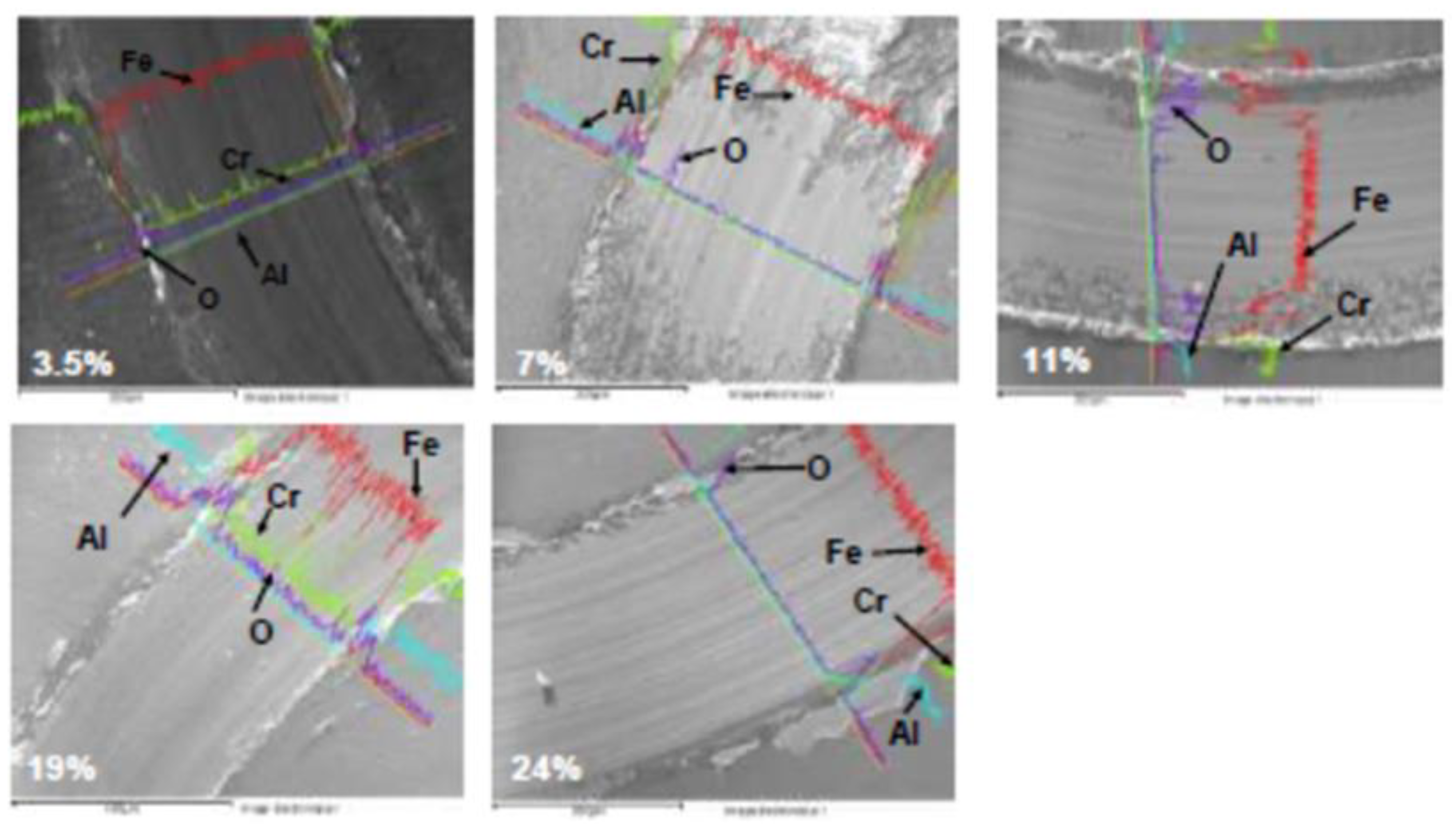
- CrAlNR films have better tribological properties than the CrAlNS case, although the maximum values of the coefficient of friction are comparable (around 0.8). However, the friction distance (without the appearance of defects) on CrAlNR is longer than on CrAlNS. This is because the presence of the c-AlN and h-AlN phases has a detrimental effect on the coefficient of friction, and subsequently on the rapid degradation of CrAlNS coatings.
- e)
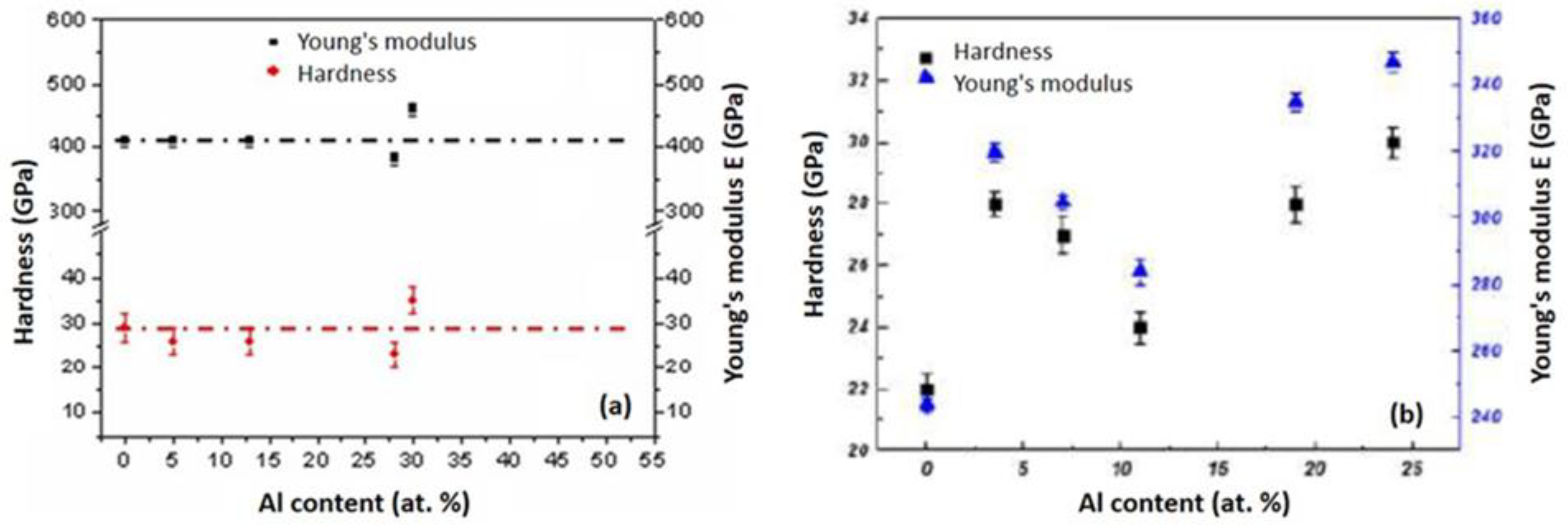
- The deposition under optimum conditions yielded maximum hardness and Young’s modulus values of 40 GPa and 465 GPa, respectively, for the CrAlNS films. In contrast, the CrAlNR layers achieved slightly lower values of 32-33 GPa and 350-352 GPa, respectively.
- f)
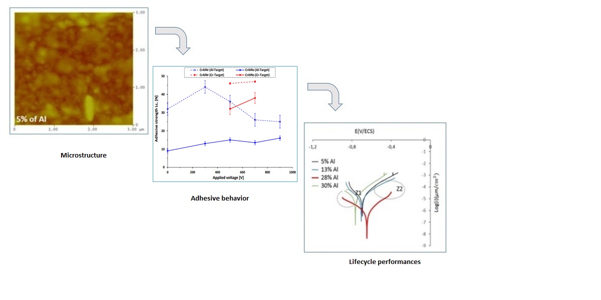
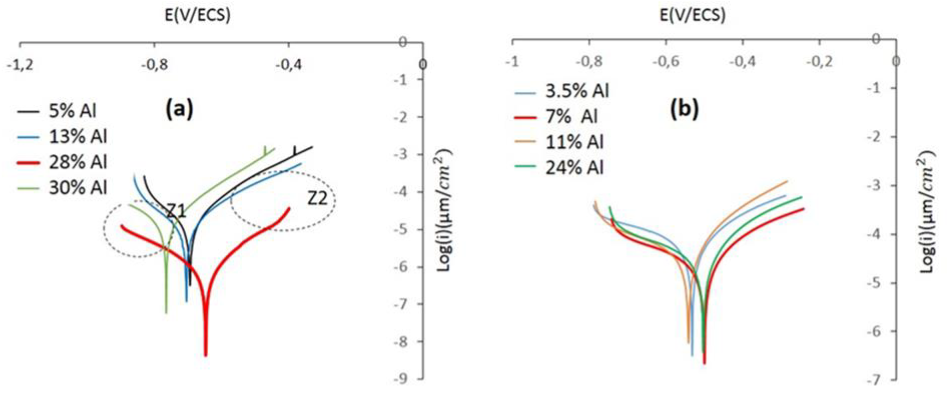
- We conclude that the CrAlNS and CrAlNR coating systems have optimal electrochemical behavior, for the 28% Al and 7% Al properties respectively. The density of growth defects (effect of aluminum incorporation and substrate rotation) has a more significant effect on corrosion behavior than other properties, such as: micro-structure, wear and tribological properties.
Acknowledgments
Conflicts of Interest
References
- Y.C. Chim, X.Z. Ding, X.T. Zeng, S. Zhang. Oxidation resistance of TiN, CrN, TiAlN and CrAlN coatings deposited by lateral rotating cathode arc. Thin Solid Films. 2009, Vol. 517, pp. 4845-4849. [CrossRef]
- Q. Chen, Y. Cao, Z. Xie, T. Chen, Y. Wan, H. Wang et al. Tribocorrosion behaviors of CrN coating in 3.5wt% NaCl solution. Thin Solid Films. 2017, Vol. 622, pp 41-47. [CrossRef]
- B. Tlili, C. Nouveau, M.J. Walock, M. Nasri, T. Ghrib. Effect of layer thickness on thermal properties of multilayer thin films produced by PVD. Vacuum. 2012, Vol. 86, pp 1048-1056. [CrossRef]
- T. Polcar, T. Kubart, R. Novák, L. Kopecký, P. Široký. Comparison of tribological behaviour of TiN, TiCN and CrN at elevated temperatures. Surface & Coatings Tech. 2005, V193, pp. 192-199. [CrossRef]
- Aouadi, K., Tlili, B., Nouveau, C., Besnard, A., Chafra, M., & Souli, R. (2019). Influence of substrate bias voltage on corrosion and wear behavior of physical vapor deposition CrN coatings. Journal of Materials Engineering and Performance, 28, 2881-2891. [CrossRef]
- B. Tlili, N. Mustapha, C. Nouveau, Y. Benlatreche, G. Guillemot, M. Lambertin. Correlation between thermal properties and aluminum fractions in CrAlN layers deposited by PVD technique. Vacuum, 2010, Vol.84, pp. 1067-1074. [CrossRef]
- Y. H. Liu, T. Fujita, A. Hirata, S. Li, H. W. Liu, W. Zhang, A. Inoue, and M. W. Chen. Deposition of multicomponent metallic glass films by single-target magnetron sputtering. Intermetallics, 2012, vol. 21, pp. 105–114. [CrossRef]
- Karimi, W. Kalss. Off-axis texture in nanostructured Ti1-x AlxN thin films. Surface and Coating Technologie. 2008, Vol. 202, 2241-2246. [CrossRef]
- X. Liu, C. Johnson, C. Li, J. Xu, C. Cross. Developing TiAlN coatings for intermediate temperature solid oxide fuel cell interconnect applications. Int. J. Hydrogen Energy, 2008, Vol. 33 189-196. [CrossRef]
- J.L. Mo, M.H. Zhu, B. Lei, Y.X. Leng, N. Huang. Comparison of tribological behaviours of AlCrN and TiAlN coatings deposited by Physical Vapor Deposition, J. Wear, 2007, Volume 263, pp. 1423-1429. [CrossRef]
- J. Yin, R. Hu, X. Shu. Closed-die forging process of copper alloy valve body: finite element simulation and experiments3 Journal of Materials Research and Technology, Volume 10, 2021, 1339-1347. [CrossRef]
- C. Jácome, C. Angulo, J.C. & Y.A astro. PVD coatings influence (TiCN, BCN, and CrAlN) on the fatigue life behavior of AISI 1045 steel for automotive applications. Int J Adv Manuf Technol 119, 3995–4009 (2022). [CrossRef]
- B.Tlili, C. Nouveau, G. Guillemot, et al. Investigation of the Effect of Residual Stress Gradient on the Wear Behavior of PVD Thin Films. J. of Materi Eng and Perform 27, 457–470 (2018). [CrossRef]
- A.Y. Adesina. Tribological Behavior of TiN/TiAlN, CrN/TiAlN, and CrAlN/TiAlN Coatings at Elevated Temperature. J. of Materi Eng and Perform 31, 6404–6419 (2022). [CrossRef]
- W. Tillmann, D. Stangier, B. Denkena et al. Influence of PVD-coating technology and pretreatments on residual stresses for sheet-bulk metal forming tools. J. Prod. Eng. Res. Devel. 10, 2016, 17–24. [CrossRef]
- K. Kaouther, D. Hafedh, Z. Lassaad et al. Mechanical Characterization of CrN/CrAlN Multilayer Coatings Deposited by Magnetron Sputtering System. Journal of Materials Eng. and Perform. 24, 2015, 4077–4082. [CrossRef]
- Z. Wu, Z. Cheng, H. Zhang, et al. Electrochemical and Tribological Properties of CrAlN, TiAlN, and CrTiN Coatings in Water-Based Cutting Fluid. Journal of Materials Eng. and Perf. 29, 2020, 2153–2163. [CrossRef]
- H.N. Shah, R. Jayaganthan. Influence of Al Contents on the Microstructure, Mechanical, and Wear properties of Magnetron Sputtered CrAlN Coatings. J. of Materi Eng and Perform 21, 2012, 2002–2009. [CrossRef]
- Ebrahimzadeh, F. Ashrafizadeh. A comparative study of surface deformation and quality of brass workpiece in contact with coated dies by pin-on-disc testing. Int. Journal Adv. Manuf. Technology 77, 2015, 609–620. [CrossRef]
- W. Shi, Q. Miao, W. Liang, Y. Liu, M. Yin, X. Xu, L. Xue. Gas-solid erosion characteristics of CrAl/CrAlN duplex layer coating deposited by RF magnetron sputtering, Surfaces and Interfaces, Vol. 22, 2021, 100843. [CrossRef]
- C. Li, L. Wang, L. Shang, X. Cao, G. Zhang, & al. Mechanical and high-temperature tribological properties of CrAlN/TiSiN multilayer coating deposited by PVD, Ceramics International, V. 47, Issue 20, 2021, 29285-2929. [CrossRef]
- K. Bobzin, C. Kalscheuer, M. Carlet, S. Schmauder, V. Guski, W. Verestek, M. Tayyab. 3D deformation modeling of CrAlN coated tool steel compound during nanoindentation. Surface and Coatings Technology, Volume 453, 2023, 129148. 2023. [CrossRef]
- E. Haye, F. Deschamps, G. Caldarella, M.L. Piedboeuf, A. Lafort, et al. Formable chromium nitride coatings for proton exchange membrane fuel cell stainless steel bipolar plates. International Journal of Hydrogen Energy, Volume 45, Issue 30, 2020, 15358-15365. [CrossRef]
- S.P. Mani, P. Agilan, M. Kalaiarasan, K. Ravichandran, N. Rajendran, Y. Meng. Effect of multilayer CrN/CrAlN coating on the corrosion and contact resistance behavior of 316L SS bipolar plate for high temperature proton exchange membrane fuel cell. Journal of Materials Science & Technology, Volume 97, 2022, 134-146. [CrossRef]
- L. Chen, X. Yu. Influence of interfacial structure on the mechanical and thermal properties of CrAlN/ZrN multilayer coatings, Materials & Design, Volume 106, 2016, 1-5. [CrossRef]
- Evrard, M. , Besnard, A. et al. (2019). Study of the influence of the pressure and rotational motion of 3D substrates processed by magnetron sputtering: A comparative study between Monte Carlo modeling and experiments. Surf. & Co.Tech., 378, 125070. [CrossRef]
- Kadam, N. R. , Karthikeyan, G., & Kulkarni, D. M. (2020). Effect of substrate rotation on the microstructure of 8YSZ thermal barrier coatings by EB-PVD. Materials Today: Proceedings, 28, 678-683. [CrossRef]
- R. Forsén, M.P. Johansson, M. Odén, N. Ghafoor. Effects of Ti alloying of AlCrN coatings on thermal stability and oxidation resistance. Thin Solid Films, Volume 534, 2013, 394-402. [CrossRef]
- M. Ahlgren, H. Blomqvist. Influence of bias variation on residual stress and texture in TiAlN PVD coatings. Surface and Coatings Technology. 2005, Vol. 200, pp. 157-160. [CrossRef]
- Wahl, K. J. , Chromik, R. R., & Lee, G. Y. (2008). Quantitative in situ measurement of transfer film thickness by a Newton’s rings method. Wear, 264(7-8), 731-736. [CrossRef]
- K.D. Bouzakis, N. K.D. Bouzakis, N. Michailidis, S. Gerardis, G. Katirtzoglou, & al. Correlation of the impact resistance of variously doped CrAlN PVD coatings with their cutting performance in milling aerospace alloys. Surface and Coatings Technology. 2008. Vol. 203, pp.781-785. [CrossRef]
- Nasser, M. , Attyaoui, S., Tlili, B., Montagne, A., Briki, J., & Iost, A. (2021). Identification of Fe-Zn coating behaviors by a new reverse approach using artificial intelligence. Materials Research Express, 8(11), 116401. [CrossRef]
- S. Khamseh, M. Nose, T. Kawabata, K. Matsuda, S. Ikeno. Oxidation Resistance of CrAlN Films with Different Microstructures Prepared by Pulsed DC Balanced Magnetron Sputtering System, Mater. Trans., vol. 51, no. 2, p. 271, 2010. [CrossRef]
- K. Rahmoun, A. Iost, V. Keryvin, G. Guillemot, N.E. Chabane Sari. A multilayer model for describing hardness variations of aged porous silicon low-dielectric-constant thin films. Thin Solid Films, Volume 518, Issue 1, 2009, 213-221. [CrossRef]
- Beliardouh, N. E. , Bouzid, K., Nouveau, C., Tlili, B., & Walock, M. J. (2015). Tribological and electrochemical performances of Cr/CrN and Cr/CrN/CrAlN multilayer coatings deposited by RF magnetron sputtering. Tribology International, 82, 443-452. [CrossRef]
- L. Wang, G. Zhang, R.J.K. Wood, S.C. Wang, Q. Xue. Fabrication of CrAlN nanocomposite films with high hardness and excellent anti-wear performance for gear applicatio. Surface and Coatings Technology, Vol. 204, Issues 21–22, 2010, 3517-3524. [CrossRef]
- L. Bait, L. Azzouz, N. Madaoui, N. Saoula. Influence of substrate bias voltage on the properties of TiO2 deposited by radio-frequency magnetron sputtering on 304L for biomaterials applications, Applied Surface Science, Volume 395, 2017, 72-77. [CrossRef]
- E.C. Romero, M.G. Botero, W. Tillmann, & al. Influence of carbon content on the microstructure, mechanical and tribological properties of CrAlCN coatings deposited by DC unbalanced magnetron sputtering. Bull Mater Sci 41, (2018), 97. [CrossRef]
- J.C. S. López A. Contreras S. D. Meister A. G. Luis, M. Brizuela, Tribological behaviour at high temperature of hard CrAlN coatings doped with Y or Zr, Thin Solid Films, Vol. 550, 2014, 413-420. [CrossRef]
- J. Tian, C. Hu, L.i Chen, Y. Lou, N. Zhao. Structure, mechanical and thermal properties of Y-doped CrAlN coatings. Transactions of Nonferrous Metals Society of China, Vol. 31, Issue 9, 2021, 2740-2749. [CrossRef]
- S.P. Mani, P. Agilan, M. Kalaiarasan et al. Effect of multilayer CrN/CrAlN coating on the corrosion and contact resistance behavior of 316 L SS bipolar plate for high temperature proton exchange membrane fuel cell. Journal of Materials Science & Technology, Vol. 97, 2022, 134-146. [CrossRef]
- B. Xia, S. Zhou, Y. Wang, H. Chen, J. Zhang, B. Qi. Multilayer architecture design to enhance load-bearing capacity and tribological behavior of CrAlN coatings in seawater. Ceramics International, Vol. 47, Issue 19, 2021, 27430-27440. [CrossRef]
- A.S. Kuprin, V.D. Ovcharenko, A. Gilewicz, G.N. Tolmachova, & al. Structural, mechanical and tribological properties of Cr-V-N coatings deposited by cathodic arc evaporation. Tribology International, Vol. 165, 2022, 107246. [CrossRef]
- Y. Wang, Ji. Y. Influence of Mo Doping on the Microstructure, Friction, and Wear Properties of CrAlN Films. J. of Materi Eng and Perform 30, 2021, 1938–1944. [CrossRef]
- Z. Wang, D. Zhang, P. Ke, X. Liu, A. Wang. Influence of Substrate Negative Bias on Structure and Properties of TiN Coatings Prepared by Hybrid HIPIMS Method. Journal of Materials Science & Technology, Vol. 31, Issue 1, 2015, 37-42. [CrossRef]
| Chemical elements | C | Mo | V | Si | Mn | Cr | S |
|---|---|---|---|---|---|---|---|
| % Wt | 0.89 | 1.5 | 0.6 | 1.3 | 0.4 | 5.8 | 0.02 |
| Coatings |
Target bias voltage (-V) |
Gas proportion |
Working pressure (µbar) |
Power of Targets (w) |
Deposition time [min] |
Output target Thickness 2-3 [μm] |
|||
|---|---|---|---|---|---|---|---|---|---|
| Cr | Al | %Ar | %N2 | Cr | Al | ||||
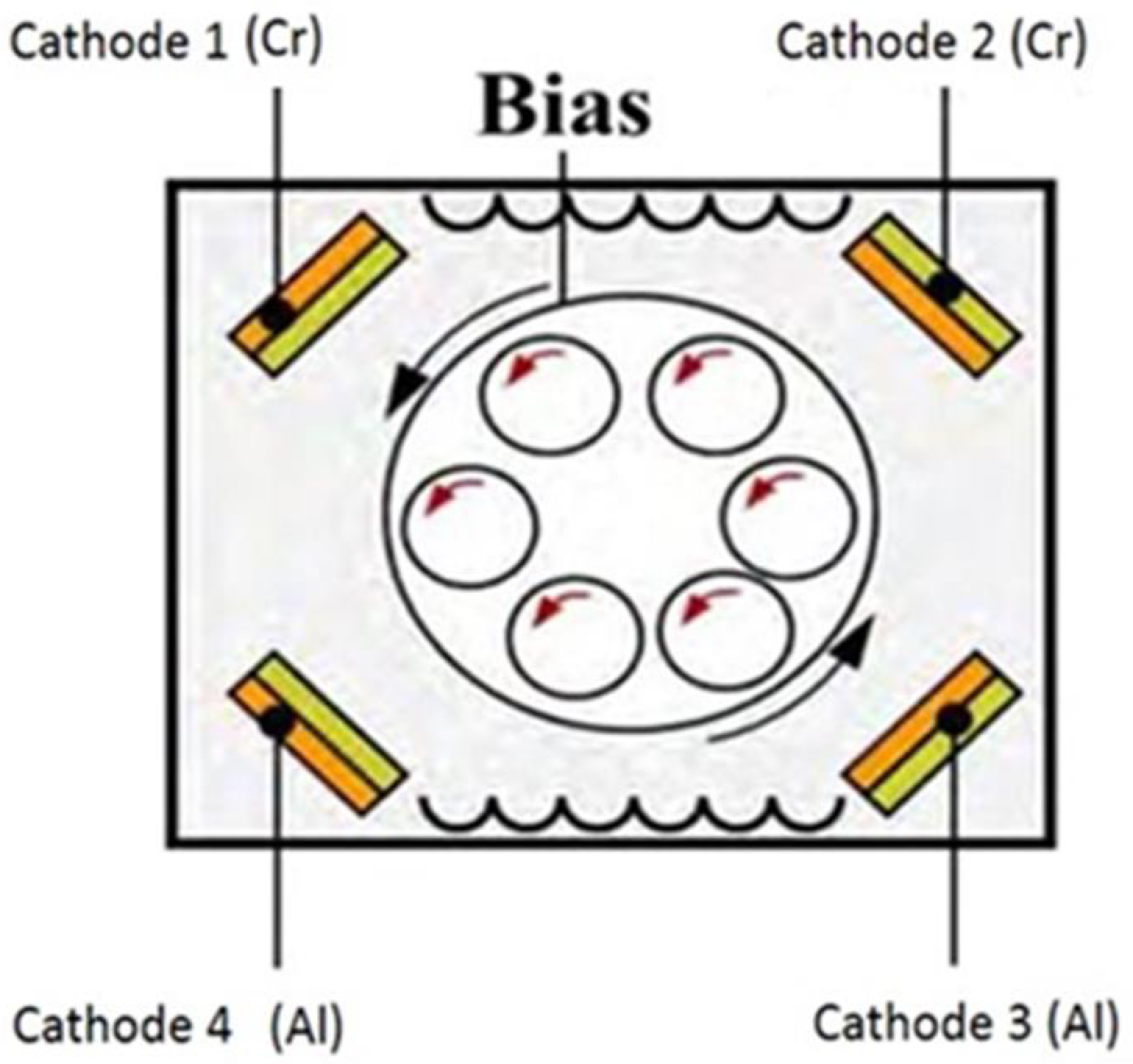
| CrAlNS | 900 | 0 | 70 | 30 | 4 | 500 | 0 | 120 | 2 |
| 300 | 500 | 100 | 2.1 | ||||||
| 500 | 500 | 250 | 2.5 | ||||||
| 700 | 500 | 350 | 2.7 | ||||||
| 900 | 525 | 450 | 3 | ||||||
| 900 | 550 | 550 | 2.1 | ||||||
| 900 | 575 | 550 | 2 | ||||||
| CrAlNR | 375 | 220 | 70 | 30 | 5 | 1500 | 500 | 120 | 2.2 |
| 225 | 1000 | 2.3 | |||||||
| 236 | 1500 | 2.5 | |||||||
| 243 | 2200 | 2.7 | |||||||
| 256 | 2800 | 2.9 | |||||||
Disclaimer/Publisher’s Note: The statements, opinions and data contained in all publications are solely those of the individual author(s) and contributor(s) and not of MDPI and/or the editor(s). MDPI and/or the editor(s) disclaim responsibility for any injury to people or property resulting from any ideas, methods, instructions or products referred to in the content. |
© 2023 by the authors. Licensee MDPI, Basel, Switzerland. This article is an open access article distributed under the terms and conditions of the Creative Commons Attribution (CC BY) license (http://creativecommons.org/licenses/by/4.0/).


