3.1. Building mathematical models
The uncertainty of the proposed linear-scan measurement method was evaluated in a measurement experiment of a small cylindrical workpiece with a small diameter of 1.5 mm and a length of 7.8 mm. A mathematical model was constructed to calculate the measurement uncertainty of the diameter and roundness. The arc output (
xi,
zi) in the rectangular coordinate system is obtained from the scanning of the linear scanning stylus. The mathematical model for the radius calculation and the uncertainty factors arising from the measurements are shown in
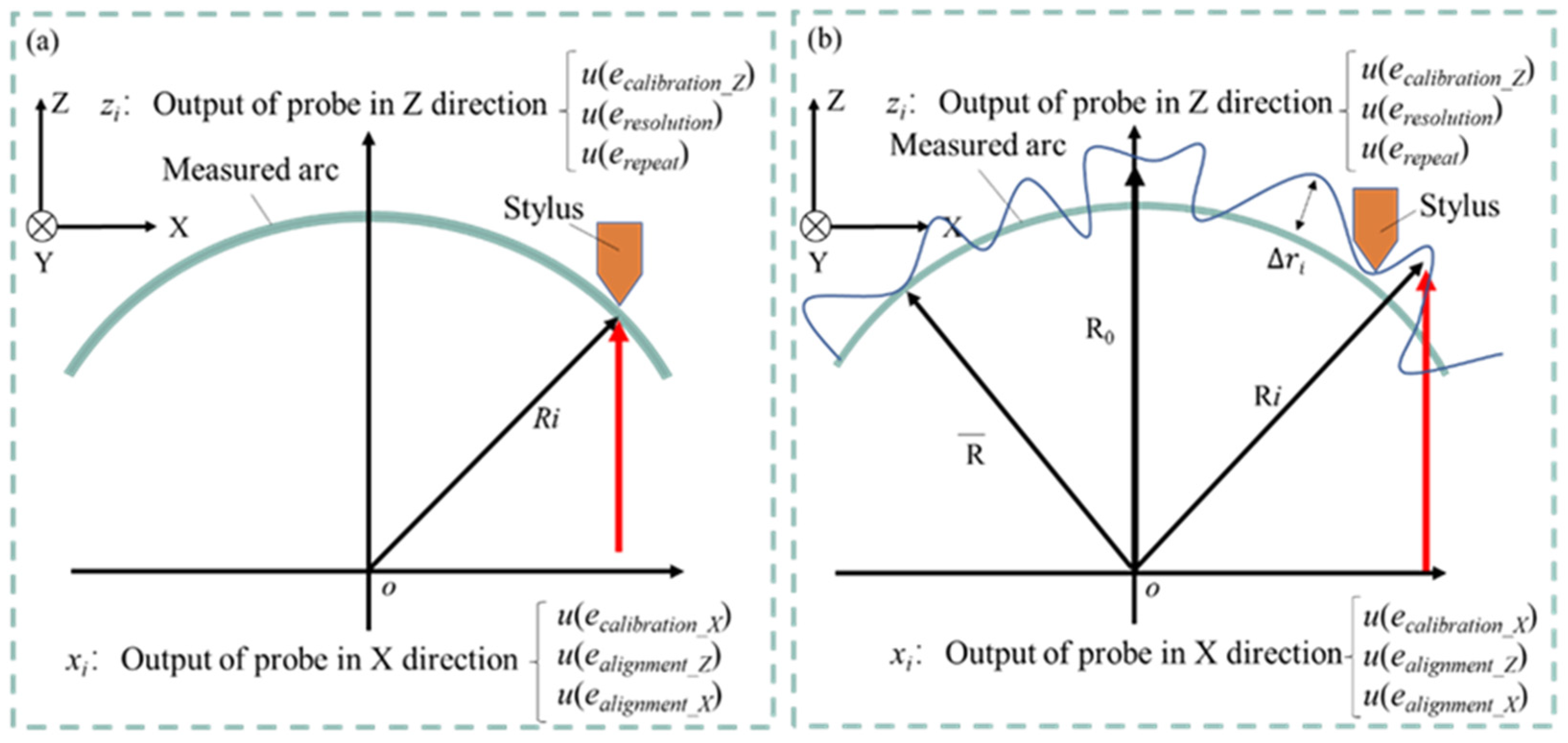
Figure 3(a). For the radius calculation, a perfect circle is assumed, and the center of the circle is set to the origin. The radius
Ri of an arbitrary measurement point is expressed in terms of the Z-axis output
zi and X-axis coordinates
xi of any measurement point using the following equation.
From equation (1), the combined standard uncertainty
u(
Ri) of the measured arc radius is expressed as:
The uncertainty coefficients in the figure are:
(1) Uncertainty coefficient of output zi in the Z-axis direction.
u(ecalibration_Z): Uncertainty of stylus calibration in the Z-axis direction.
u(eresolution): Uncertainty due to stylus resolution.
u(erepeatt): Uncertainty of repeated measurements.
(2) Uncertainty coefficient of output xi in the X-axis direction
u(ecalibration_X): Uncertainty of stylus calibration in the X-axis direction.
u(ealignment_Z): Uncertainty due to orientation error around the Z-axis of the workpiece.
u(ealignment_X): Uncertainty due to orientation error around the X-axis of the workpiece.
In summary, the combined standard uncertainty
zi of the Z-axis output and the combined standard uncertainty of the X-axis coordinate
xi are expressed by the following equations (3) and (4), respectively.
For the calculation of roundness, it is assumed that there is a deviation from the approximate circle center rather than the radian of a perfect circle, and the approximate circle center is set as the origin. The radius
Ri of any measurement point, the radius
R0 of the vertex, and the X-axis coordinate
xi are used to represent the Z-axis output
zi of any measurement point with the following equation.
The radius
Ri after the stitching process is calculated according to Equation (6).
Δ
ri is the radial deviation at any measured point and Δ
r0 is the radial deviation at the arc apex.
Square both sides of equation (5), substitute into equations (7) and (8), and rearrange.
From Eq. (9), the combined standard uncertainty
u(Δ
ri) of the radial deviation of any measurement point can be expressed as:
The uncertainty factors shown in
Figure 3(b) are similar to the radius measurement model described above. Therefore, the combined standard uncertainty
zi for the Z-axis output and the combined standard uncertainty for the X-axis coordinate
xi are expressed by Eq. (6) and Eq. (7), respectively. The uncertainty of the radius after the suturing process is expressed by the following equation, using the combined standard uncertainty
u(
Ri) of the radius obtained from Eq. (6) and the number of arc divisions N.
3.2. Measurement uncertainty evaluation
1. Uncertainty coefficient of output zi in the Z-axis direction.
The standard uncertainty of each uncertainty factor is derived using appropriate evaluation methods.
(1) Uncertainty of stylus calibration in Z-axis direction u(ecalibration_Z).
The calibration of the Form Talysurf PGI420 used was performed with the dedicated master sphere shown in
Figure 4(a). The Pt value is the minimum maximum width after linear expansion of the arc measured at the known radius value shown in
Figure 4(b), including shape error of the master sphere, shape error of the stylus tip diameter, electrical noise in the system, and mechanical and environmental disturbances Pt value = 0.0337μm is in the radial direction, but assuming the presence in the Z-axis and X-axis directions, respectively, and a larger estimate, the uncertainty of the stylus calibration in the Z-axis direction uncertainty can be expressed by the following equation.
(2) Uncertainty due to stylus resolution u(eresolution).
The Form Talysurf PGI420 uses a linear scanning stylus with a vertical resolution of 3.2 nm. The uncertainty due to the resolution of the stylus is considered to be a ±1.6 nm rectangular distribution, which can be determined using the Type B evaluation method by the following equation.
(3) Uncertainty of repeated measurements u(erepeat).
The results of repeated measurements using the Form Talysurf PGI420 on the cross-sectional circle of a small cylindrical workpiece with a diameter of 1.5 mm were used to estimate the uncertainty due to measurement error: The repeatability was 59.93 nm based on 10 repeated measurements, and the uncertainty of the repeated measurements can be determined using the Type A evaluation method according to the following formula.
2. Uncertainty coefficient of the x-axis coordinate xi.
(1) Uncertainty of stylus calibration in the X-axis direction u(ecalibration_X).
When picking up the output
zi in the Z-axis direction as the uncertainty coefficient, it is assumed that Pt values exist in the Z-axis and X-axis directions, respectively, so the uncertainty of the stylus calibration in the X-axis direction is the same as that in the X-axis direction, expressed by the following equation.
(2) Uncertainty due to orientation error around the Z-axis of the workpiece u(ealignment_Z).
The uncertainty caused by the workpiece attitude error is calculated by establishing a mathematical model of the measurement error, and the calculated value of the measurement error is used to determine the uncertainty by B-type evaluation.
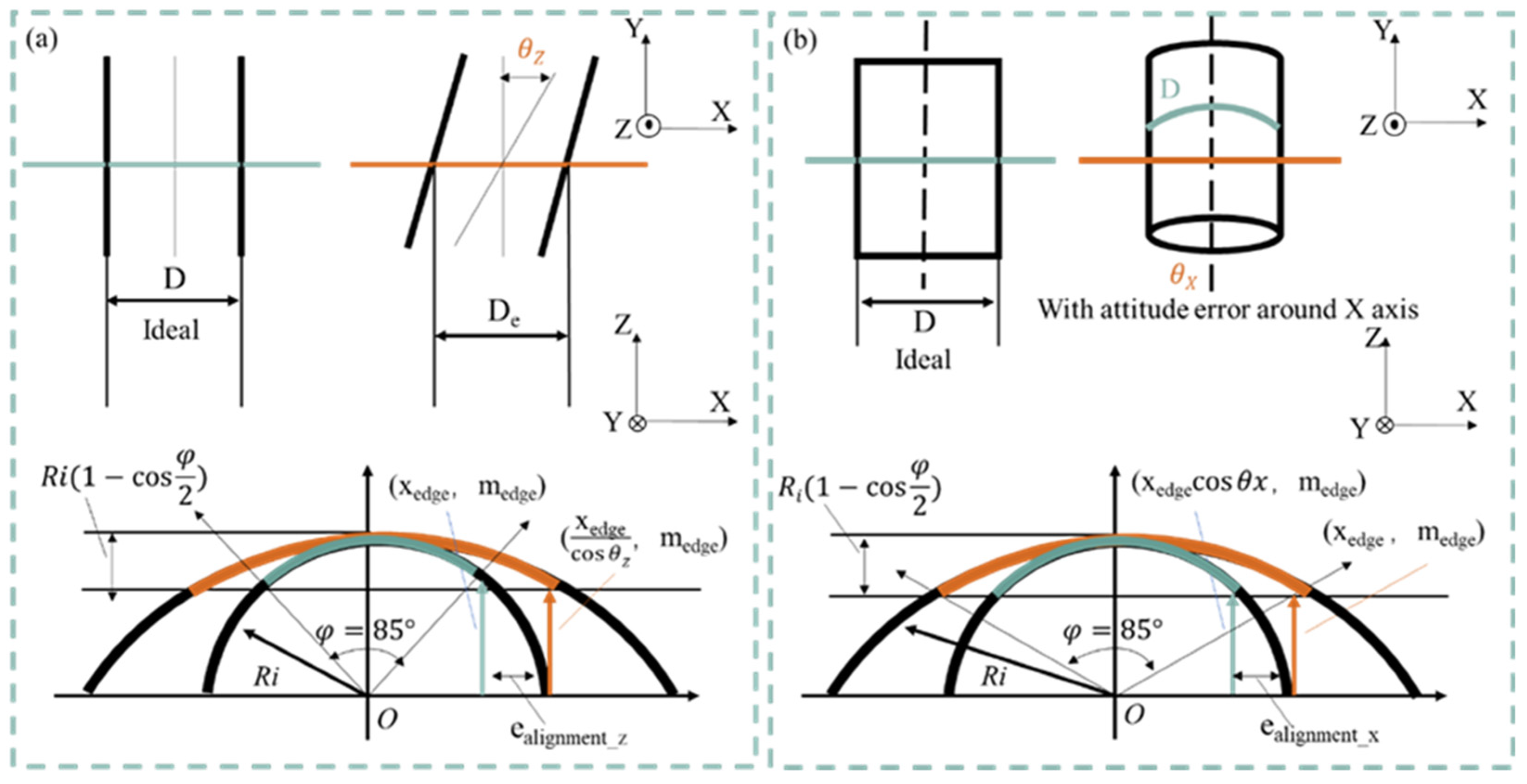
Figure 5(a) shows a schematic diagram of the effect of the orientation error of a cylindrical workpiece around the Z-axis. The diameter of the workpiece is D, the radius is R, the coordinates of the acquired arc endpoints are (x
edge, z
edge), and the angle of the attitude error is θ
Z. The attitude error around the Z-axis causes the measurement result of the geometric circle of the geometric cylinder to appear as an ellipse with its main axis in the X-axis direction. An error occurs in the X-axis coordinates because an arc of φ = 85°, i.e., an arc of height h from the vertex, is extracted regardless of the workpiece diameter, as shown in Equation (17). If the error angle is ±θ
Z° and this error has a rectangular distribution, the uncertainty due to the posture error around the Z-axis is represented by the following equation.
In the actual measurement, the alignment of the rotary table and the scanning of the stylus were repeatedly performed so that the obtained arc length converged to the minimum and the error angle
θZ was measured as small as possible. Assuming an error angle of ±1° at this point, the uncertainty due to the pose error around the Z-axis can be obtained by substituting the radius after the stitching process into equation (18) as follows.
(3) Uncertainty due to orientation error around the X-axis of the workpiece u(ealignment_Z).
Figure 5(b) shows a schematic diagram of the effect of the attitude error around the X-axis on a cylindrical workpiece. The diameter of the workpiece is D, the radius is R, the coordinates of the arc endpoints are obtained as (x
edge, z
edge), and the angle of the orientation error is
θX. The orientation error around the X-axis causes the measurement of the geometric circle of the geometric cylinder to appear as an ellipse of the main axis in the Z-axis direction. The error in the X-axis coordinates is because the arc of height
h is extracted from the vertex, just as in the case of the directional error around the Z-axis. If the error angle is ±θ
X° and the error has a rectangular distribution, the uncertainty caused by the positional error around the X-axis is given as follows.
In the actual measurement, the manual stage is moved in the Y-axis direction with the stylus in contact with the plane of the mounting table and aligned with the inclined stage to minimize displacement output variation. The error angle θ
X is measured as small as possible. Assuming that the error angle at this point is ±0.1°, the uncertainty caused by the attitude error around the X-axis is obtained by substituting the radius after the stitching process into equation (9) as follows.
Table 1 and
Table 2 summarize the calculated results for each uncertainty. From these results, the combined standard uncertainty
zi for the Z-axis output and the combined standard uncertainty
xi for the X-axis coordinates can be expressed respectively by the following equations.
Using the calculated uncertainty, the combined standard uncertainty
u(
Ri) of the measured arc radius can be obtained from equation (23) as follows Substitute the combination of (
xi, zi), i.e., the coordinates of the arc endpoint (x
edge, z
edge) = (0.50575, 0.55280), for which the
u(
Ri) obtained from the measurement is the maximum.
The uncertainty of the radius after the suturing process can be obtained by substituting the values obtained in equation (13) into equation (11) to obtain the following equation.
The uncertainty of the diameter measurement is twice the uncertainty of the radius.
Calculating the extended uncertainty for k=2 yields the following.
As can be seen above, the uncertainty of the diameter measurement of the 1.5 mm small cylindrical workpiece using the linear scanning method, was estimated to be ±47.24 nm, achieving a target measurement uncertainty within ±0.1 μm.
Table 3 summarizes the results of the standard uncertainty.
Using the calculated uncertainty, the combined standard uncertainty
u(Δ
ri) of the radial deviation of any measured point can be obtained from Eq. (10) as follows Substituting the combination of (
xi,
mi), the coordinates of the endpoint of the arc (
xedge,
zedge) = (0.50575, 0.55280) and the radius after the stitching process, for which u obtained from the measurement
u(Δ
ri) is maximum, the following equation is obtained.
Using the same assumptions as in equations (6) and (29), the combined standard uncertainty
u(Δ
zq) of roundness can be expressed as follows.
Substituting the uncertainty calculated in Eq. (26), the combined standard uncertainty
u(Δ
zq) is obtained from Eq. (27), as shown in Equation (31) below.
Calculating the extended uncertainty for
k= 2, the following equation is obtained.
As can be seen above, the uncertainty in the roundness measurement of a small cylindrical workpiece with a diameter of 1.5 mm was estimated to be ±95.44 nm using the linear scanning method, achieving a target measurement uncertainty of ±0.1 μm or less.
Table 3 summarizes the results of the standard uncertainty.
3.3. Variation of uncertainty due to change in workpiece diameter
The purpose of calculating the measurement uncertainty when the workpiece diameter varies by simulation is to investigate the cylindrical workpiece diameter suitable for roundness measurement using a roundness measuring machine, which is a linear scanning type measurement method. Among the uncertainty coefficients described in the previous section, the uncertainty coefficient
u(
ealignment_Z) due to the orientation error around the workpiece Z-axis and the uncertainty coefficient
u(
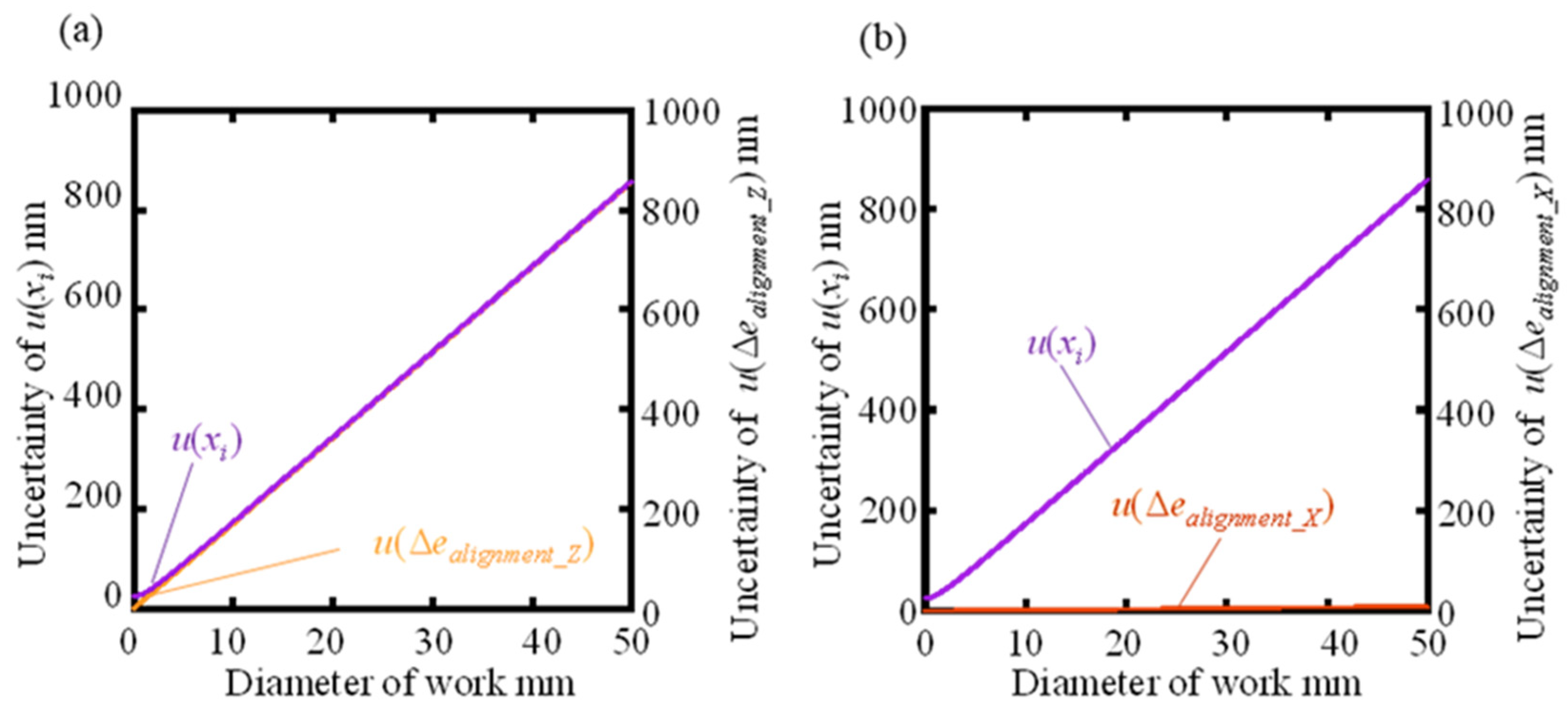
ealignment_X) due to the orientation error around the workpiece X-axis vary significantly with the change of the workpiece diameter, while the others are considered to be almost unchanged. Using equations (13) and (14), the graphs of the uncertainty
u(
xi) in the x-axis coordinate as the workpiece diameter varies from 0.01 mm to 50.00 mm are shown in
Figure 6(a) and (b).
Figure 6(a) shows that
u(
ealignment_Z) increases with increasing diameter and becomes almost the same as
u(
xi), but the change in
u(
ealignment_X) is smaller. This means that
u(
ealignment_Z) is the dominant factor in the variation of
u(
xi). This is due to the setting of the attitude error angles
θZ = ±1° and
θX = ±0.1° considering the alignment method and stylus resolution, while
θZ is estimated to be greater than
θX.
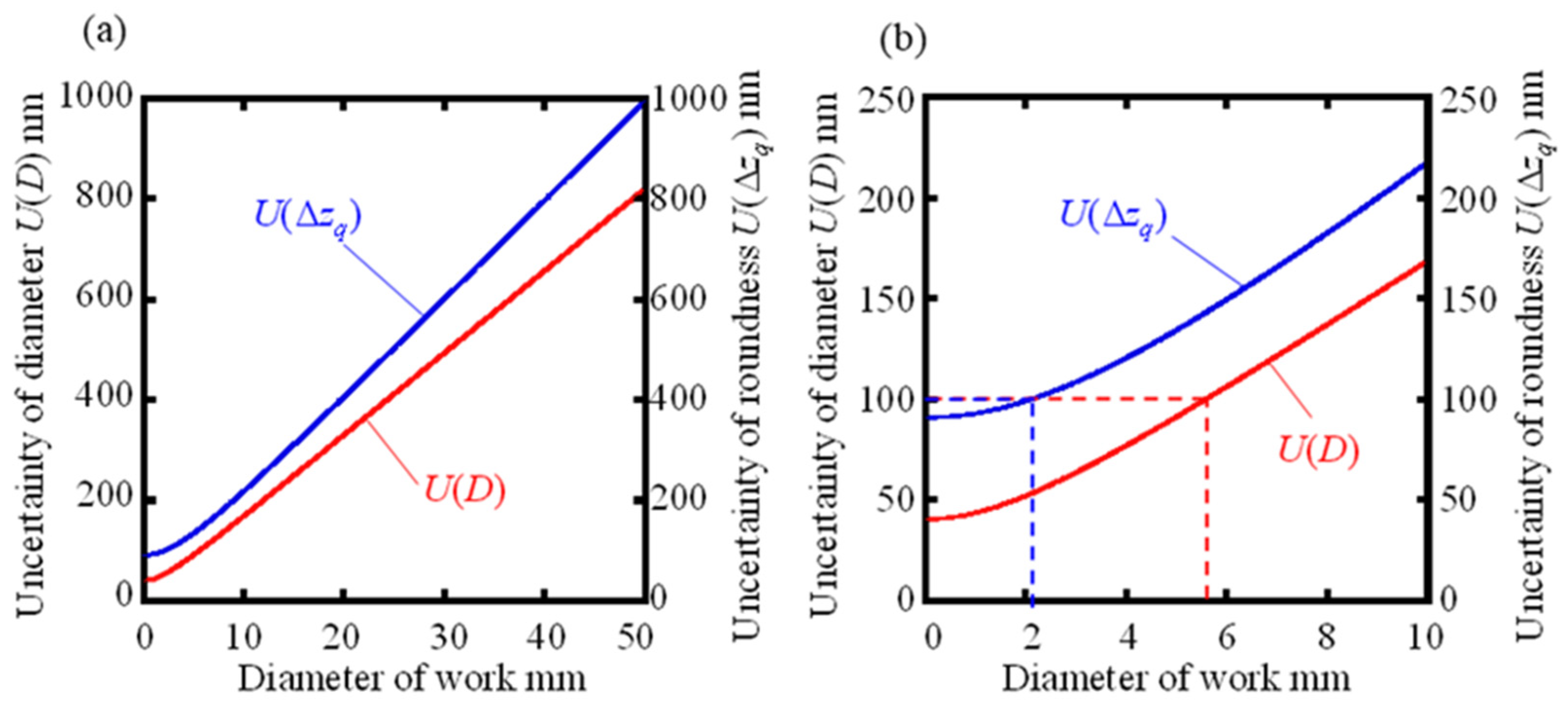
Figure 7(a) shows the graphs representing the variation of the extended uncertainty
U(
D) for diameter and the extended uncertainty
U(Δ
zq) for roundness, created by substituting
u(
xi) and other standard uncertainties, which vary with workpiece diameter, showing that both
U(
D) and
U(Δ
zq) increase as the workpiece diameter increases due to the effect of
u(
xi). increases with increasing workpiece diameter due to the effect of
u(
xi).
Figure 7(b) shows a graph for expanding the range of workpiece diameters from 0.01 mm to 10 mm. From this graph, it can be read that the conditions under which the target measurement uncertainty within ±0.1 m of the workpiece diameter can theoretically be achieved are
U(
D) of 5.58 mm or less and
U(Δ
zq) of 2.11 mm or less when the attitude error angle
θZ = ±1° and
θX = ±0.1°.
In the previous simulations, the attitude error angle was set to
θZ = ±1° and
θX = ±0.1°, but improving the alignment increases the upper limit of the workpiece diameter that satisfies the target measurement uncertainty. What has room for improvement is the attitude error angle
θZ around the Z-axis. Thus,
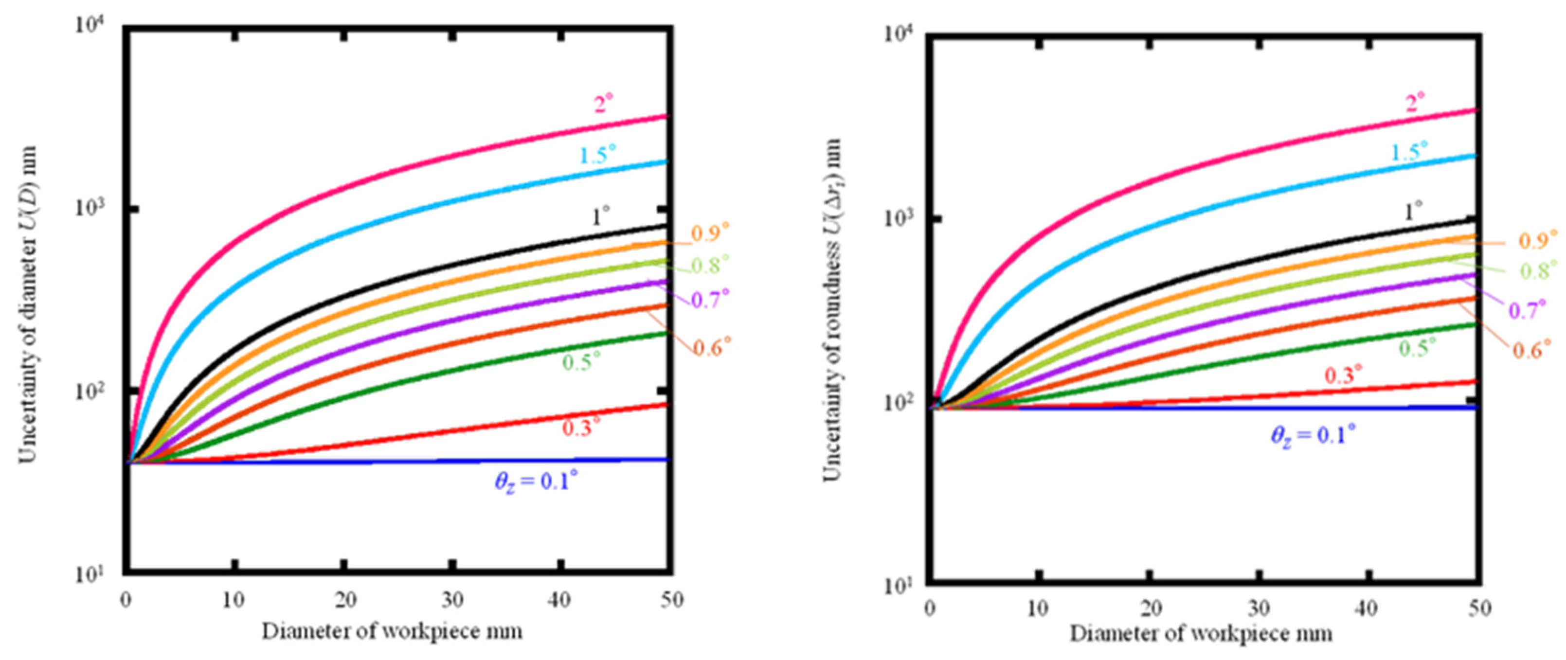
Figure 8(a) and (b) show the extended uncertainty
U(
D) in diameter and the extended uncertainty in roundness when the attitude angle error occurs in a rectangular distribution with
θZ = ±0.1°, ±0.3°, ±0.5°, ±0.6°, ±0.7°, ±0.8°, ±0.9°, ±1°, ±1.5°, and ±2° The variation of the uncertainty
U(Δ
zq). The upper limit of the workpiece diameter for which the target uncertainty of diameter and roundness can reach ±0.1 μm at each attitude error angle
θZ is calculated from the graphs and summarized in
Table 3.
Table 3 shows that when measuring large-diameter cylindrical workpieces, it is desirable to make
θZ as convergent as possible by more precise alignment; if it can be kept less than
θZ = ±0.8°, the proposed method can cover all diameters below about 3 mm, which are difficult to measure with the rotary scanning method. The proposed method can cover all diameters less than 3 mm, which are difficult to measure with the rotational scanning method. If
θZ can be further reduced, the proposed method can also be used for workpieces with larger diameters; if the alignment can reach
θZ =
θX = ±0.1°, the diameter limitation of the workpiece theoretically no longer exists. However, as the workpiece diameter increases, the measurement range in the Z-axis and X-axis directions expands, which increases the uncertainty and limits the measurement range of the used measuring machine, which may lead to an upper limit of the workpiece diameter.
