1. Introduction
We have much to learn from historic buildings. The fact that they are still standing is obvious, but unfortunately often not appreciated. Those buildings have resisted the forces of nature and decay for hundreds of years: something must have been done right and possibly could be replicated. Thus, the aim of this paper is to analyze existing cob buildings to provide guidance for practitioners on the analysis of existent cob vernacular buildings. Furthermore, such guidance could as well be used for the design of new sustainable and resilient ones, which is a field that have recently received increased attention [
1,
2,
3,
4].
The study of vernacular architecture is important as it has the potential to contribute to the global efforts to attain sustainable development. Of special interest is the study of earthen vernacular architecture whose important role for example in the development of zero-energy in dry and desertic zones, as studied by Alrashed
et al. [
5], and in aspects such as energy consumption reduction and increased thermal comfort performance, as presented by Li
et al. [
6], has been highlited.
Even though cob has a nonlinear structural behaviour [
7], it presents an initial linear relationship between stress and strain up to a level of about 30 % of its peak strength [
8]. This indicates that if the loads acting on the structure do not cause stresses beyond the linear elastic range of the material; cob structures may be studied with a simplified linear analysis. Linear analyses are easier and faster to perform than nonlinear analyses. Thus, it is of interest to find out up to what point the different values of the parameters influencing the response of the structure will allow to perform a simplified linear analysis with enough degree of accuracy. To verify this assumption and justify the use of linear analyses to study existent cob buildings, a linear parametric analysis has been performed. This analysis tries to identify the influence of geometric parameters, as well as external actions applied to the structure in the response of cob walls. The main objectives of this analysis are:
To identify the levels assigned to the different parameters for which a linear analysis may still hold valid for the study of cob walls;
To identify the possible failure modes of the walls if those limits are exceeded;
To better understand the advantages and disadvantages of a simplified linear analysis for the study of cob walls.
Furthermore, the parametric analysis presented in this paper could be used to verify whether the wall geometries used in practice are adequate and inform in the design of new cob or alternative modern earthen-based [
9] buildings. The models aim to cover representative remaining earthen vernacular buildings in Ireland [
10], which typically are single storied, regular in plan, longer than wider and without rigid diaphragms to ensure a
“box-like” structural behaviour. The methodology and results presented in this work could be extrapolated for its application on buildings with similar characteristics elsewhere. The influence of wall voids, gables, chimneys, or the variability on the mechanical properties of cob in the structural behaviour of the walls are not covered in this paper, this may be addressed in further works applying a more advanced and detailed analysis as suggested in [
11].
The results presented in this paper consist of a series of response surfaces and parametric equations with which it is possible to compute safety factors and collapse multipliers (within the range of values studied). Based on those results, it is concluded that traditional cob walls in Ireland are very robust. Relatively high acceleration values, unlikely to happen in a low seismic hazard region such as Ireland, would be needed to start the collapse mechanisms studied or cause yielding in typical vernacular cob walls. Furthermore, the equations generated with the refined regression models, can be used by practitioners as a first approach to estimate the safety levels of existing cob buildings with similar characteristics.
2. Materials and Methods
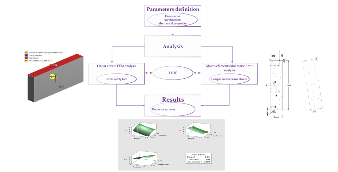
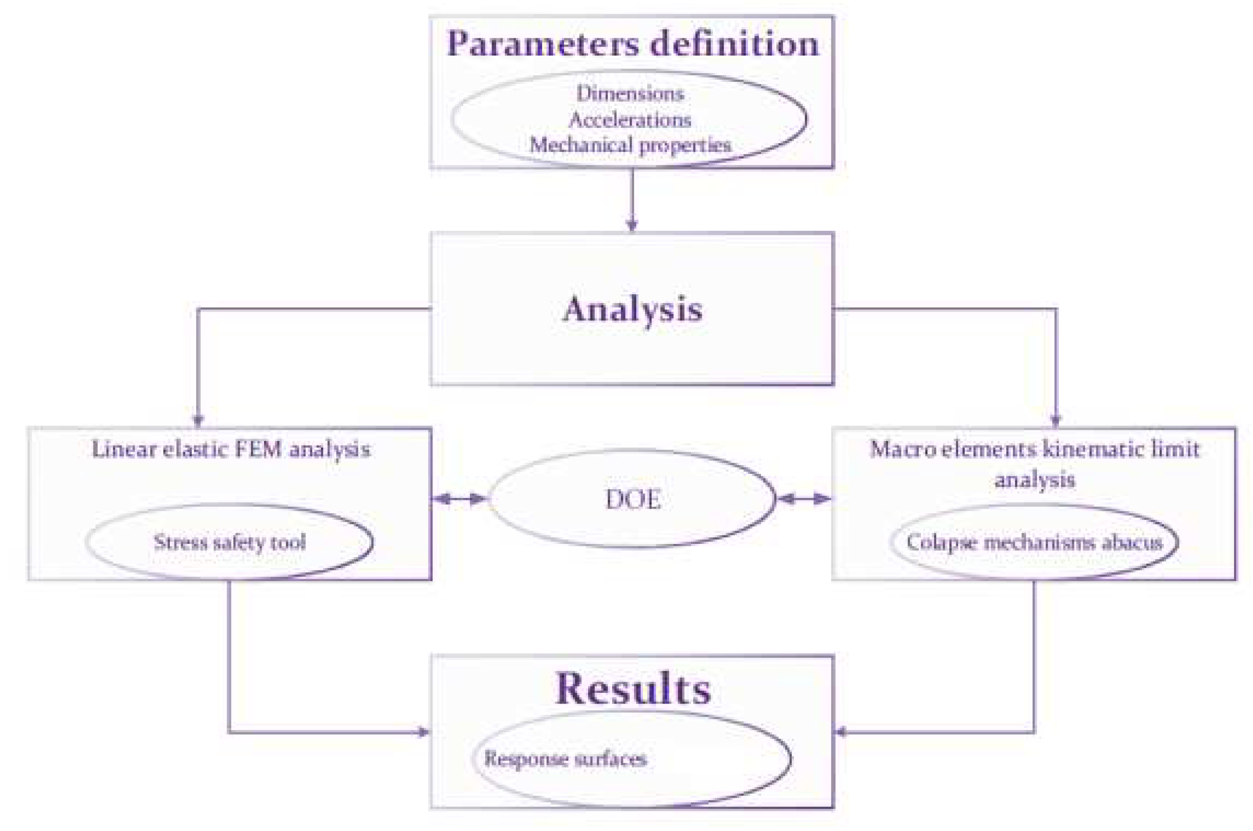
The methodology followed to perform the parametric analysis of cob walls consisted in three stages; parameters definition, Finite Element Method (FEM)/Macro element kinematic limit analyses, and interpretation of the results (see
Figure 1). Two analyses approaches were followed with the aim of exploring the pros and cons of each of them and provide alternatives to practitioners: linear elastic FEM analysis and macro elements kinematic limit analysis.
2.1. Parameters
The parameters studied were the walls dimensions and mechanical properties, as well as the accelerations to which cob walls may be subjected to during earthquakes. The
“best-guess” fixed cob’s mechanical properties values used in this parametric analysis correspond with those reported in [
8,
12], as those are two of the most recent and complete studies done to determine cob’s properties. The values are summarized in
Table 1.
Currently, a National Inventory of Architectural Heritage (NIAH) which identifies, records, and evaluates the post 1700 architectural heritages in Ireland is available (
https://www.buildingsofireland.ie/). Unfortunately, the NIAH is limited to providing an overall description of the buildings and a summarised appraisal of their value; it does not record technical information which may be of interest for their study. Dimensions of traditional earthen vernacular buildings in Ireland are only generally recorded by several authors [
13,
14,
15,
16,
17] and unfortunately there is not a comprehensive database containing such information. The geometric parameters adopted correspond to the values reported by such researchers based on studies of surviving cob buildings and records of historical cob buildings in Ireland. These values are summarized in
Table 2.
Finally, regarding the dynamic actions acting on cob walls, Ireland is a region characterised by a low seismic activity. This fact may justify the use of simplified methods of analysis to describe cob buildings structural behaviour as it is presumed that the surviving vernacular cob buildings would not experience nonlinear behaviour caused by lateral accelerations. The same can also be said for newly constructed cob buildings.
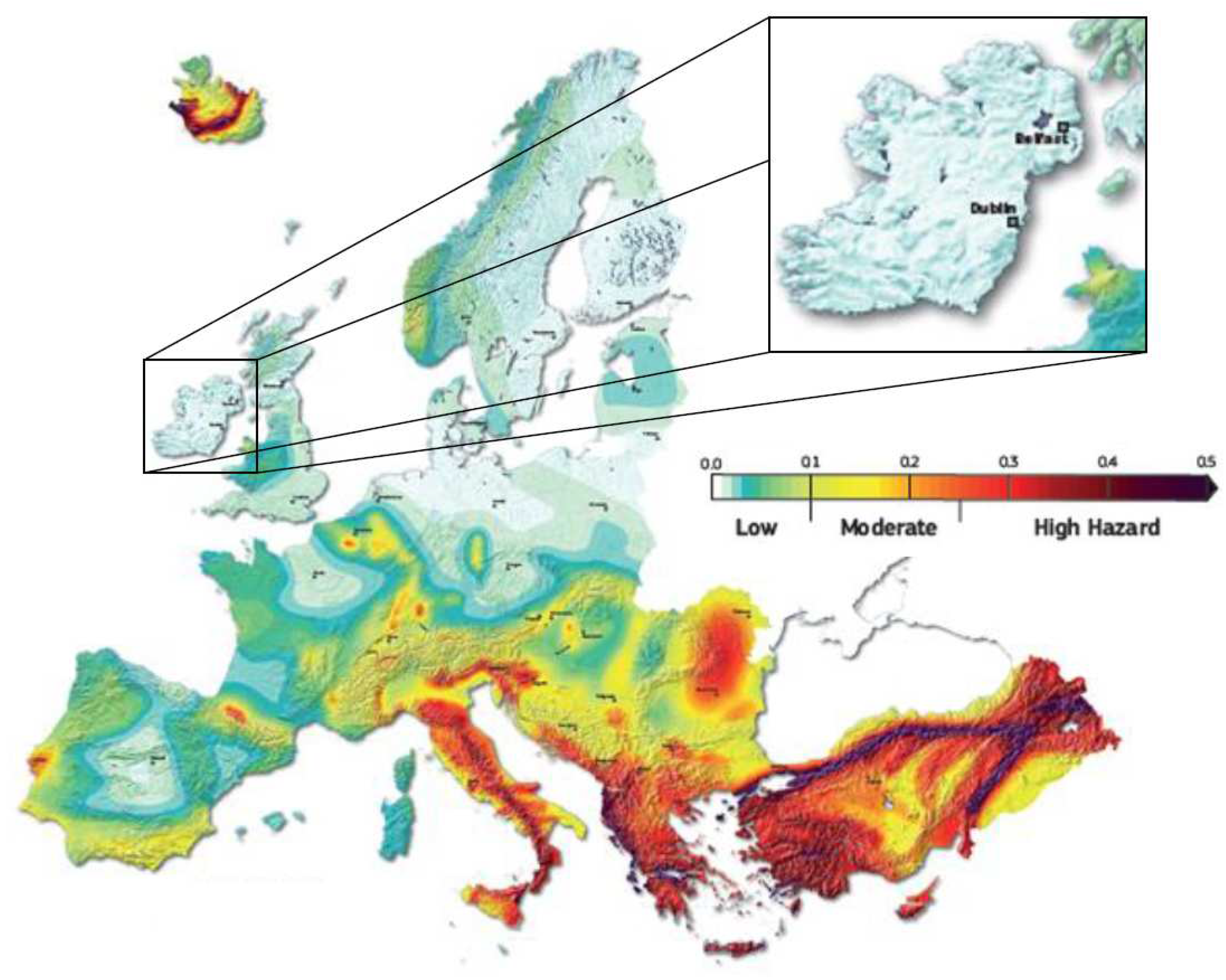
The Seismic Hazard Harmonization in Europe (SHARE) project produced a series of ground motion hazard maps for various spectral ordinates and exceedance probabilities in Europe.
Figure 2 shows the Peak Ground Acceleration (PGA, in
g) map of Europe for a
exceedance probability in 50 years. The acceleration values for a low seismicity area, and in this case the type of area correspondent to Ireland, can go from 0 up to
. The minimum and maximum values adopted for this parametric analysis were of
and
(
and
), respectively. Even though these acceleration values seem to be quite small, damage in earthen structures has been reported at similar intensities [
18]. Furthermore, as it is intended that the methodology presented in this chapter could be extrapolated and applied in other regions where buildings with similar characteristics exists, i.e. United Kingdom and North of France, it was considered as appropriate to explore the effect of earthquakes in cob structures.
The simplified models studied in this parametric analysis are static models. The dynamic accelerations caused by an earthquake in an existent cob structure were simplified into static inertial forces by using D’Alembert’s principle. This principle stablishes that
“a mass develops an inertial force proportional to its acceleration and opposing it” [
20]. It is also acknowledged that:
Further work, not discussed within this paper, would be needed to extend the scope of this parametric analysis and verify these two statements.
2.2. Linear elastic FEM analysis
A linear elastic FEM analysis was performed using ANSYS [
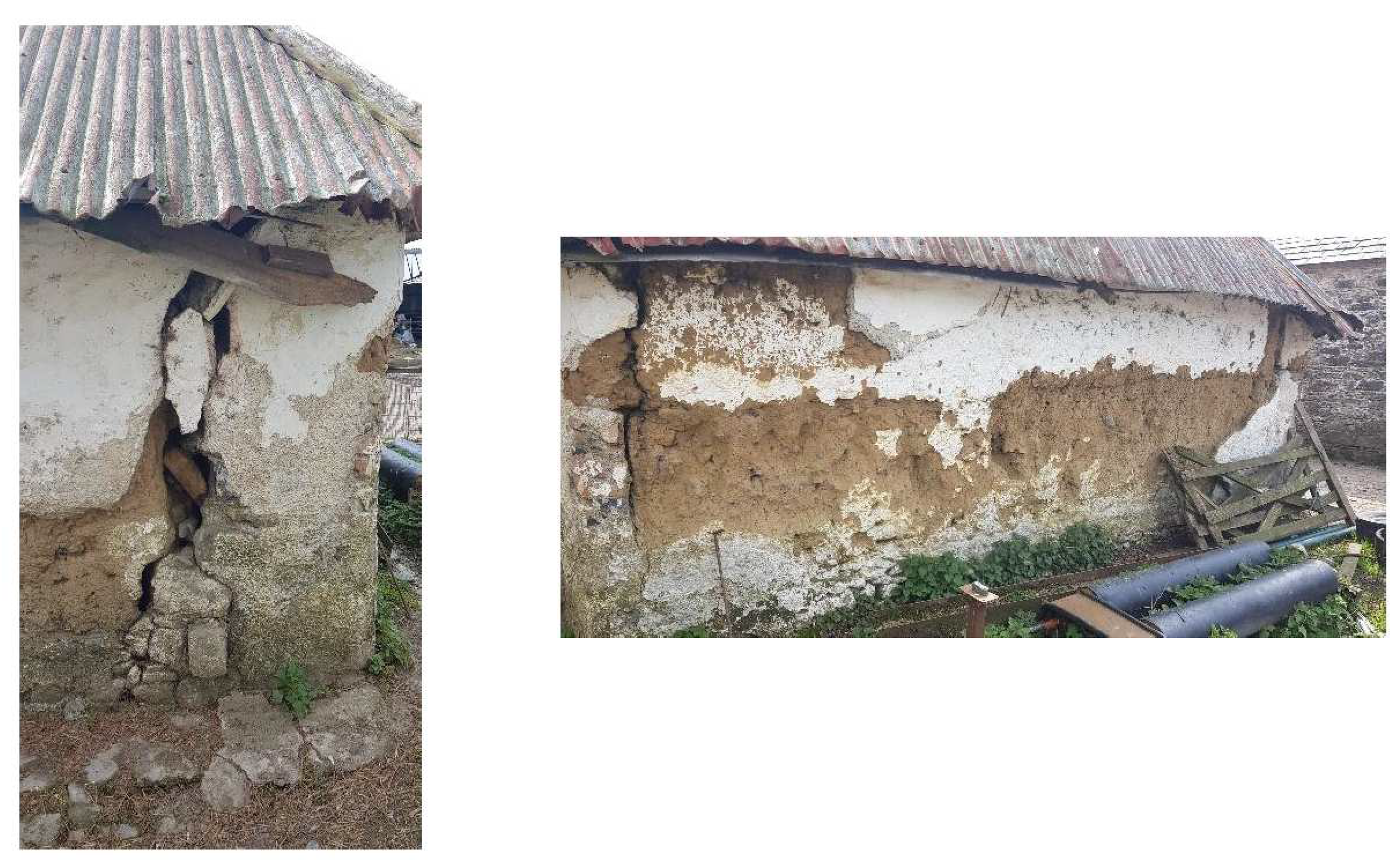
21]. It was decided to study the response of the walls subjected to both in-plane as well as out-of-plane behaviour due to the multidirectional nature of dynamic actions. For either case, a free-standing cob wall fixed (translational degrees of freedom constrained) at its bottom was simulated. This assumption is justified by the fact that most earthen vernacular buildings in Ireland do not have rigid diagram roofs (lack of bond beam, roof trusses directly placed on top of cob wall). Thus, cob walls do not present a
“box-like” behaviour and most of the time act individually to support the actions action upon them. Moreover, vertical cracks are quite common, especially at corners (see
Figure 3), which would cause the detachment of perpendicular wall connections easing their out-of-plane overturning under horizontal loads.
These assumptions were adopted with the aim of simulating a general
“worst-case scenario” in which a cob wall, part of a surviving cob building in Ireland, may be found. When dealing with existing structures which have cultural heritage value, a detailed study of the structure is desirable to avoid the design of over conservative interventions which may endanger the historic fabric [
22]. Therefore, the assumptions adopted for specific case studies must be based in the results provided by a structural integrity inspection after which the following may be found:
Wall interconnectivity (perpendicular walls providing out-of-plane support);
Top restrain at roof level;
“Box-like” behaviour (provided by a strengthening/retrofitting intervention).
Any of these factors would improve the structural response of the building and if they are neglected, the design of the intervention may result to be too invasive. On the other hand, wall voids and the presence of damage or decay would diminish the structure capacity.
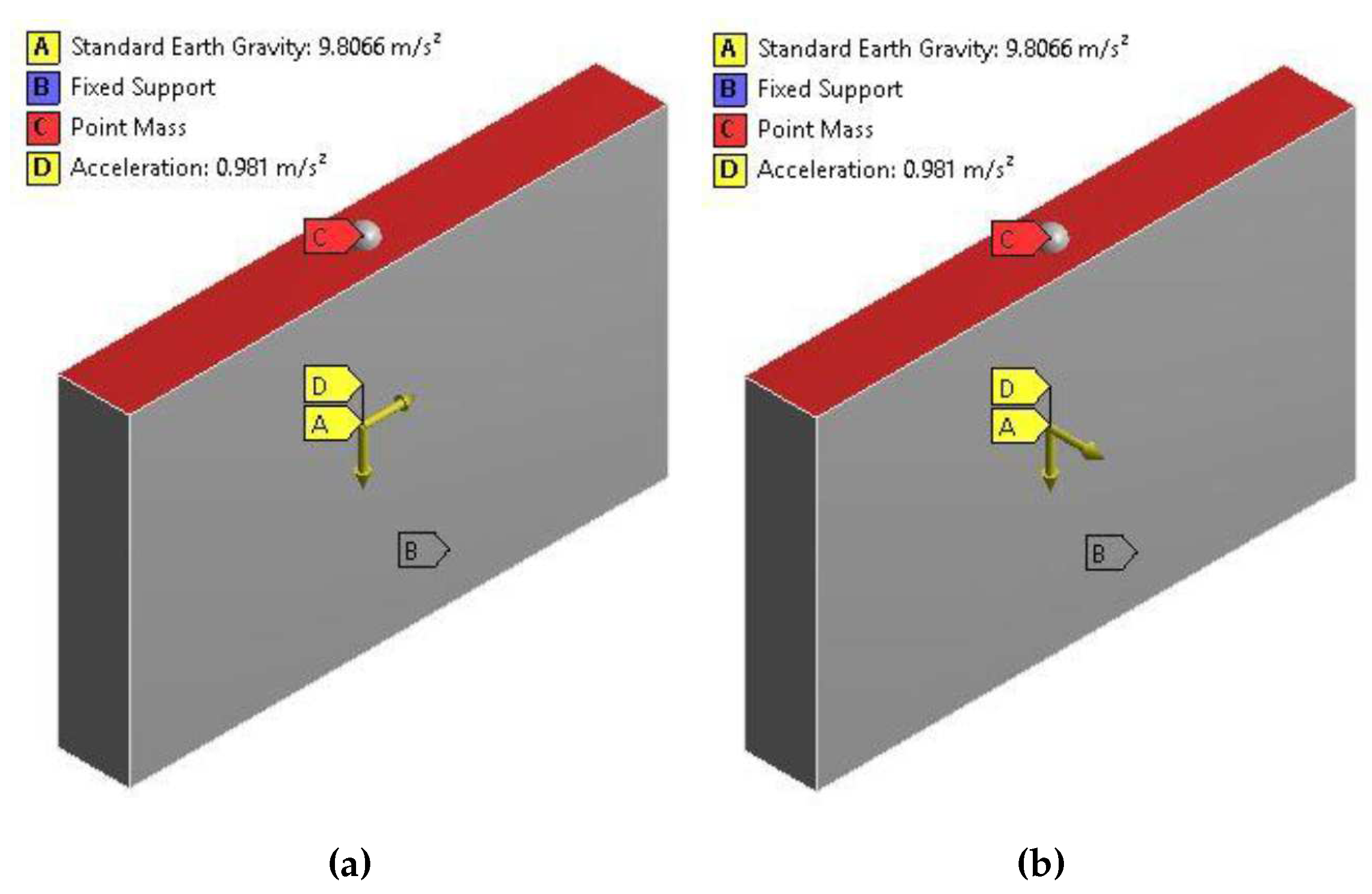
The walls were subjected to their own weight, to an external force at their top simulated as a concentrated mass, representing the loads transferred by the roof, and finally to a horizontal acceleration representing the effects of dynamic loads on the wall. The point mass at the top of the wall was assumed as that of a thatch roof with a thickness of
(including battens) and a self-weight of
[
23] with a tributary span of
giving a value of
for every meter of wall length. The setup of the in-plane and of the out-of-plane models are shown in
Figure 4 (a) and
Figure 4 (b), respectively. The finite element used was the SOLID186 [
24] and the constitutive material model adopted was a simple linear elastic model.
The response of the structure was monitored with the help of a Mohr-Coulomb stress safety tool. This tool is based on the Mohr-Coulomb theory for brittle materials and uses the principle stress values to determine the occurrence of failure. Safety factors for yielding,
, and for the ultimate,
, capacity of the material are computed with Equation
1 and Equation
2, respectively [
25].
Where and are the maximum and minimum principal stresses, and are the material ultimate tensile and compressive strengths, and and are the material yielding tensile and compressive strengths.
Strictly speaking, the tool provides a distribution of safety factors throughout the model as it bases its calculations on the independent distributions of maximum and minimum stresses and not in the absolute principal stresses, developed most likely at two different locations of the model. Therefore, the minimum value of such distribution is reported as the minimum factor of safety. The compressive strength of common brittle materials is usually much greater than their tensile strength. In this analysis, this assumption is considered to be valid for cob as well. In fact, it is assumed that cob’s tensile ultimate strength corresponds to only
of its compressive ultimate strength [
26]. The Mohr-Coulomb stress safety tool takes direct account of this theory and is often considered to provide conservative results.
2.3. Macro elements kinematic limit analysis
A second method of analysis was implemented to compare the results obtained with the simplified FEM analysis. This method is based on the abacus of collapse mechanisms reported by the New Integrated Knowledge based approaches to the protection of cultural heritage from Earthquake–Induced Risk (NIKER) European project. The abacus of collapse mechanisms basically classifies the collapse mechanisms into two categories: in-plane and out-of-plane mechanisms.
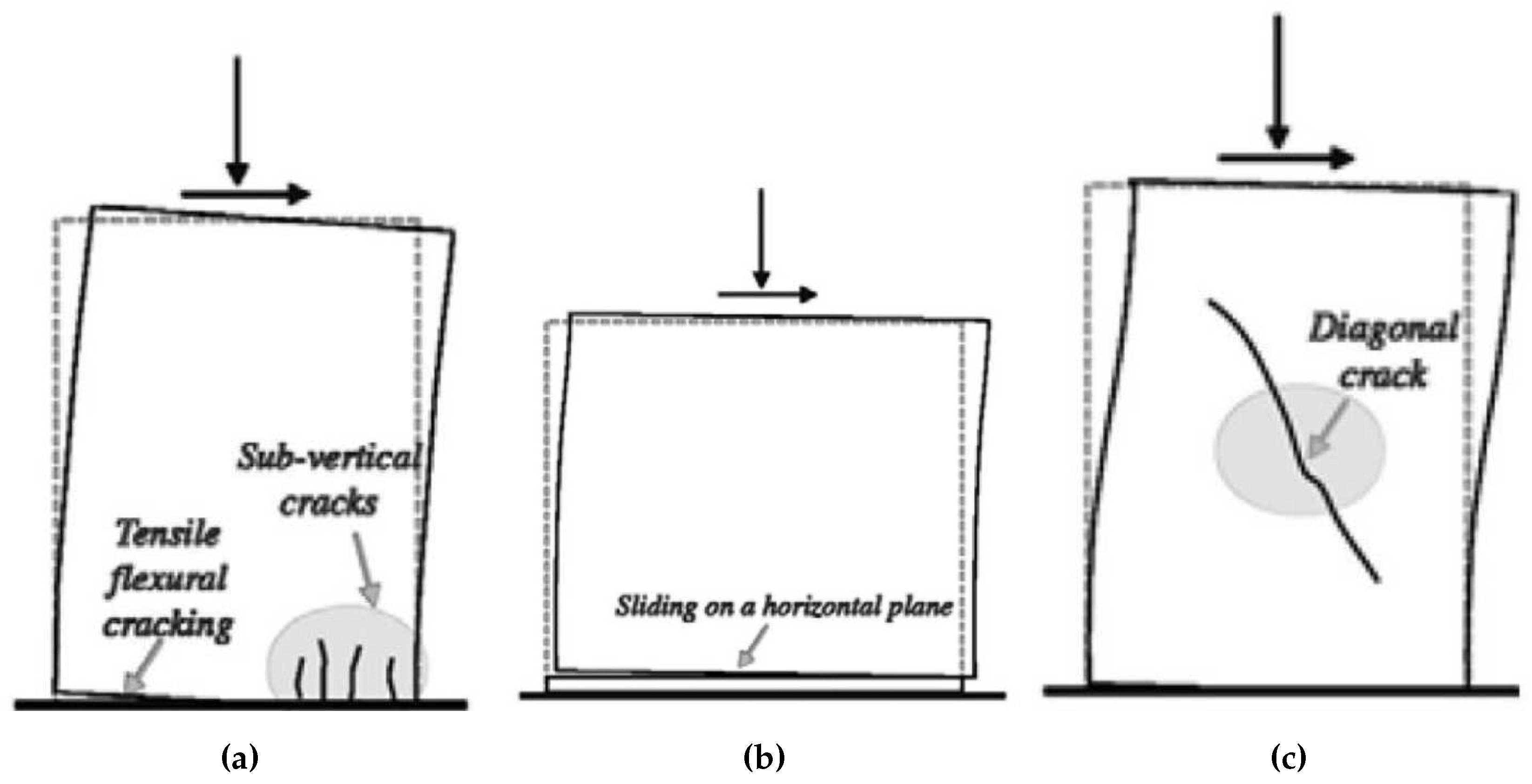
The identified in-plane damage caused by horizontal loads consist mainly in rocking, sliding shear failure and diagonal cracking (see
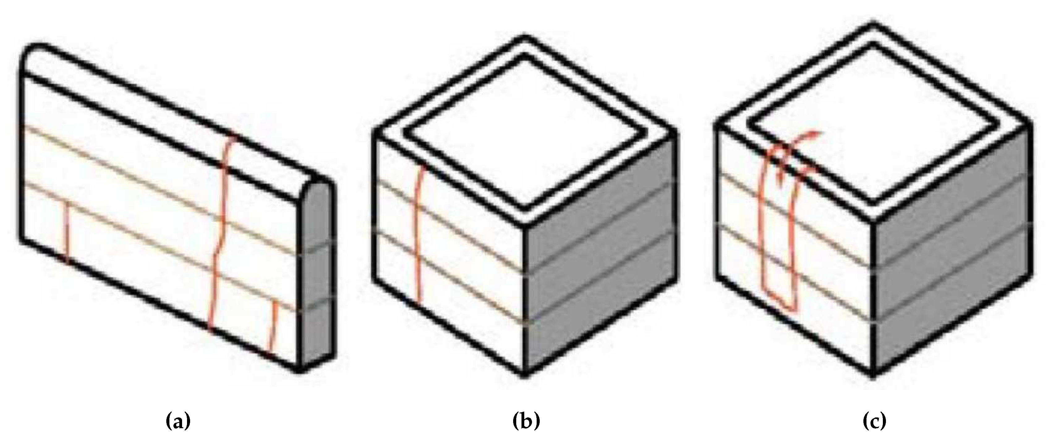
Figure 5). On the other hand, the out-of-plane damages are mainly characterized by the development of vertical cracks. Vertical cracks may either start from the bottom or from the top of the wall and some run through the entire height of the wall. This causes the separation of important segments of the wall and can lead to the overturning of the element (see
Figure 6).
The macro elements kinematic limit analysis consists basically in finding the equilibrium condition under which, for a certain value of
coefficient, the studied collapse mechanism will form [
27,
28]. Thus,
is defined as the seismic mass multiplier that leads to the formation of the collapse mechanism assumed and eventually to the element failure [
29]:
Where a is the ground acceleration and g is the gravity acceleration.
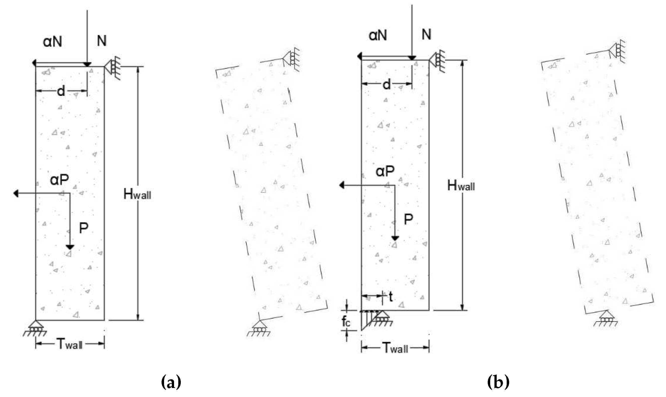
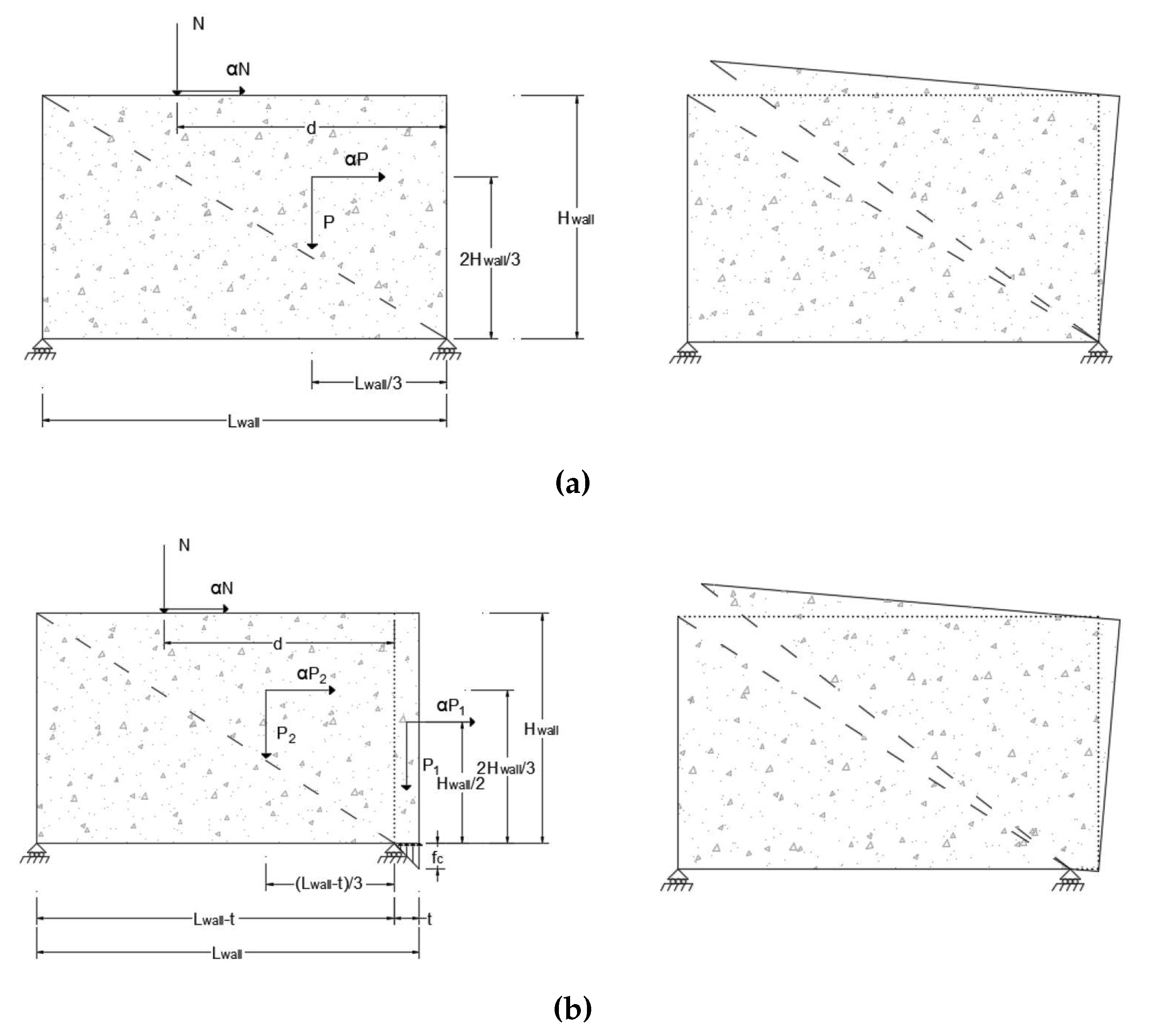
The out-of-plane mechanism considered in this parametric analysis is presented in
Figure 7. The thickness of the wall is represented by
, its height by
and its length by
. It is assumed that cob has zero tensile strength and that no internal sliding would happen, in other words, the walls behave as rigid bodies and rotate while supported in two idealized pined supports. For the case shown in
Figure 7 (a), it was assumed that cob has infinite compressive strength and the bottom support is located at the edge of the wall. On the other hand, for the case presented in
Figure 7 (b) the compressive strength of the material,
, is taking into account and the bottom support is located at a distance
t from the edge of the wall (this is a conservative assumption, a more realistic one would consider the location of the support at a distance of
from the edge of the wall). The force
P represents the self-weight of the wall and the force
N the external loads transferred from the roof. To compute
N a thatch roof with a thickness of
(including battens) and a self-weight of
[
23] has been considered with a tributary span of
giving a value of
for every meter of wall length.
The equilibrium condition of the rigid body for the case presented in
Figure 7 (a) is expressed in Equation
4 from where the expression to compute the
coefficient is obtained (see Equation
5). It is worth noting that for this parameter analysis the distance
d was assumed to be half of the wall thickness, thus, placing the external loads over the centroid of the wall.
To find the equilibrium condition of the rigid body shown in
Figure 7 (b), it is necessary to find the value of
t at which the support is located from the edge of the wall. This distance is obtained by equating the vertical forces acting on the wall with the force developed at the support as a function of the material compressive strength,
. Thus, for a unitary segment of wall (
length):
And the seismic mass multiplier is calculated using Equation
7.
The in-plane mechanism considered in this parametric analysis is presented in
Figure 8. It is the result of diagonal cracking on the cob wall. For the case shown in
Figure 8 (a) it was assumed that cob has infinite compressive strength (along with zero tensile strength and no internal sliding) and the bottom support is located at the edge of the wall whereas that for the case presented in
Figure 8 (b), the compressive strength of the material,
, is taken into account and the bottom support is located at a distance
t from the edge of the wall (this is a conservative assumption, a more realistic one would consider the location of the support at a distance of
from the edge of the wall). For the in-plane analysis the distance
d was considered to be equal to half the distance between the wall supports.
The formulas used to calculate the seismic mass multiplier coefficient for case (a) and case (b) are presented in Equation
8 and Equation
10, respectively. The value of
t was calculated using Equation
9. These equations were obtained by applying equilibrium equations of the vertical stabilizing forces,
P and
N, and the horizontal destabilizing forces,
and
.
Where
represents cob density. The values of
for the four mechanisms presented were computed using MATLAB [
30] scripts.
2.4. Design of experiments
A Design Of Experiments (DOE) technique was used for both the linear elastic FEM analysis and the macro elements kinematic limit analysis to obtain meaningful results and, at the same time, to reduce the computational effort required. The DOE for the linear elastic FEM analysis was performed directly in ANSYS using the design exploration module [
31], whereas the DOE for the macro elements kinematic limit analysis was performed using the statistics software Minitab [
32].
A Central Composite Design (CCD) method was implemented with the objective of studying the influence of the input parameters (geometric and accelerations for the FEM models and geometric for the limit analysis models) in the responses of the models (
and
for the FEM models and seismic mass multiplier for the limit analysis models). A full CCD was selected for the design type as this method is available as the default option in both applications and is the most commonly used method for the DOE to create response surfaces [
33]. Adequate values for the distance of the star points were selected based on Equation
11 in order to ensure rotatability and provide a constant prediction variance.
Where
is the axial spacing of the design points and
is the number of points in the factorial part of the design, usually
, where
k is the number of factors. More details about the CCD method can be consulted elsewhere [
34]. Finally, the design points generated with the CCD were used to build the response surfaces by applying a full 2nd-order polynomial algorithm. Then, the main effect and interaction effect plots were analysed and a second response surface was created taking into account only those statistically significant terms (
) to simplify the regression model.
For both FEM and macro elements models the mechanical properties of cob were maintained constant. The wall geometric parameters and the levels of acceleration were used as input parameters for the FEM models in the DOE and the yield and ultimate safety factors computed were used as output parameters. On the other hand, only the geometric parameters were used as input parameters for the macro elements models and the computed coefficients were the correspondent output parameters.
3. Results and Discussions
A free-standing wall fixed at its base and subjected to in-plane forces may be idealized as a plane-stress problem where the thickness of the wall could be neglected without significantly affecting the results. On the other hand, the same wall subjected to out-of-plane forces could be idealized as a plane strain problem, and in this case, the length of the wall would not affect the results. The results of the parametric analysis performed have confirmed these simple, but important, concepts and would be described in more detail in this section.
3.1. FEM out-of-plane analysis
The DOE using a CCD rotatability design with four factors (length, height, thickness and acceleration) generated 49 design points. The order in which the design points were generated by the CCD was random to avoid the effect of any nuisance variable in the output parameters (randomization is of paramount importance in the design of physical experiments, but it does not affect the numerical parametric analysis performed in this thesis).
The minimum value computed for was equal to . This value was obtained for a wall with length, height, thickness, and subjected to a lateral acceleration of . Almost all values computed for were equal to , which is the cap value provided by ANSYS, and this means that the safety factor is equal or greater than . Unfortunately, this cap value prevented the statistical analysis to develop any meaningful plots of the effect each input parameter has in . The only useful conclusion that could be drawn from this situation is that within the ranges explored of the input parameters, the walls would not be subjected to stress values that may lead to their collapse.
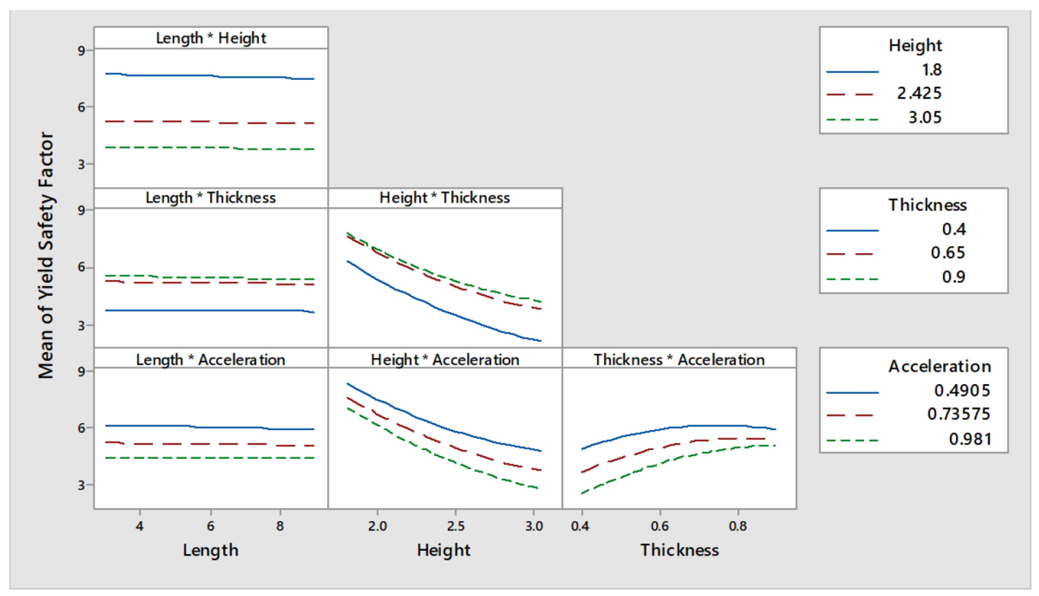
An effective way of interpreting the effect that the input parameters have in the response (
and
) is by analysing the main effects and interaction effects plots presented in
Figure 9 and
Figure 10, respectively (only the plots for
are presented and discussed). Such plots have been obtained after performing an Analysis Of Variance (ANOVA). The main effect plots show that the value of
are not influenced by the length of the wall as the first curve to the left of
Figure 9 is almost constant. On the other hand, height, thickness and acceleration proved to be parameters influencing
.
It is expected that the higher and the thinner a wall is, the more critical it would be its safety when subjected to out-of-plane forces. This is confirmed by the results obtained from the parametric analysis as can be seen in the curves corresponding to wall height and wall thickness from
Figure 9. The higher is the value for the height parameter, the lower is
. On the other hand, the higher is the thickness, the higher is
. The second and third curves of
Figure 9, corresponding to the main effects of wall height and thickness, show a non-linear relationship with
whereas that the relationship of the acceleration seems to be linear. Furthermore,
also seems to be affected by the thickness/acceleration interaction since the three curves seem to converge for the higher values of thickness, as can be seen in the lower right curve of
Figure 10.
The full quadratic model was refined by removing the non-significant terms. By taking into account only those statistically significant terms previously discussed, the expression shown in Equation
12 was obtained. Equation
12 can be used to estimate the value of
for every combination of wall height (
in
m), thickness (
in
m) and lateral acceleration (
a in
) within the range of values explored by the analysis presented in this paper. In this equation the length of the wall is not included, as its effect on the out-of.plane response is non-significant, and this confirms the comment made at the beginning of the section regarding the fact that the length of the wall was expected not to influence the out-of-plane response of the wall.
If Equation
12 is evaluated for a wall height of
, a thickness of
and an acceleration of
, then,
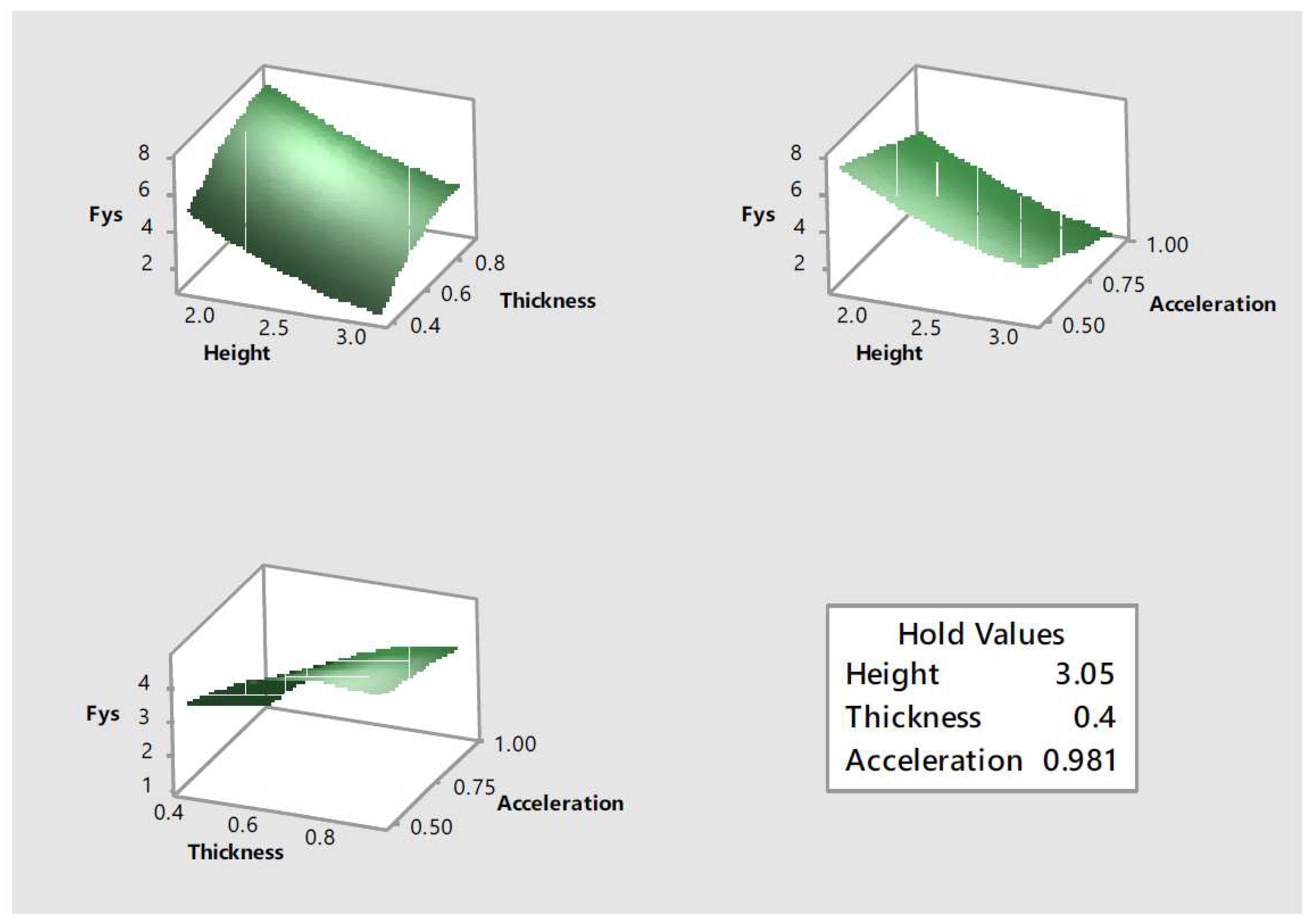
. This indicates that even under the most adverse combination of values for the parameters explored, and based on the assumptions adopted, the material would not reach its yield point. Equation
12 was also used to create the response surfaces shown in
Figure 11. Each one of the response surfaces show information regarding the effect of two input parameters, while the third one is kept constant at its more critical value, in the response,
. These response surfaces reflect the quadratic effect the input parameters have in the response as initially observed in the main effect plots.
3.2. FEM in-plane analysis
The DOE using a CCD rotatability design with four factors (length, height, thickness and acceleration) generated 49 design points. The minimum value computed for was equal to . This value was obtained for a wall with length, height, thickness, and subjected to an acceleration of . All values computed for were equal to , which is the automatic cap value used by ANSYS, and this prevented the statistical analysis to develop any meaningful plots of the effect each input parameter has in . Once again, all that can be said from those values is that within the ranges explored of the input parameters the walls would not be subjected to stress values that may lead to their collapse.
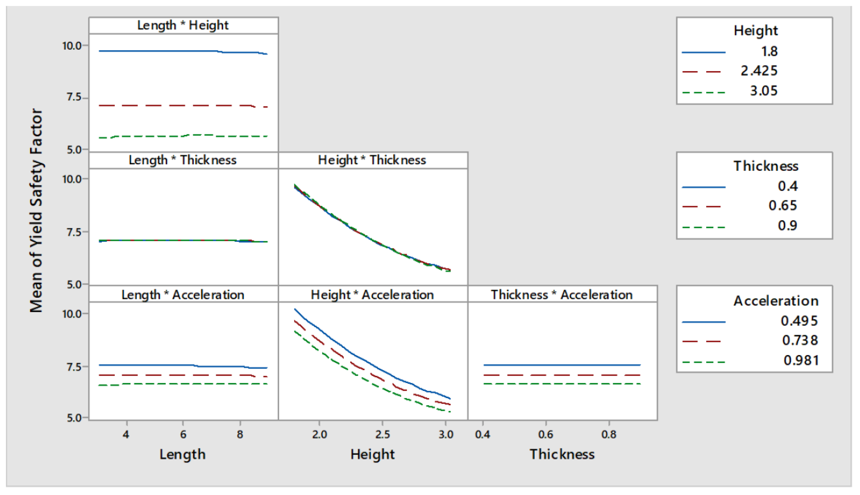
It would be expected that the length of the wall played an important role in the wall in-plane response. Bulky walls tend to fail by shear whereas that slender walls tend to top up or fail by crushing at their base. Nevertheless, as the boundary conditions adopted prevented the in-plane rotation of the wall and, since the levels of stress created by the low levels of acceleration adopted did not exceed the yielding point of the material, the parametric analysis did not capture properly the effects of wall length. This is confirmed by the main effect plots, shown in
Figure 12, which effectively show that the values of
are neither influenced by the length or the thickness of the wall (the first and third curves from the left of
Figure 12 are almost constant). On the other hand, height and acceleration seem to be parameters influencing
. The taller is a wall and the higher is the acceleration to which it is subjected, the more probabilities of damage are expected. Effectively, the trend depicted by the main effects plots show that a lower
is obtained for the upper values of both height and acceleration. Furthermore, it can also be observed that the interaction between parameters is negligible as none of the curves shown in
Figure 13 seem to intersect each other.
The full quadratic model was refined by removing the non-significant terms. By taking into account only those statistically significant terms the expression shown in Equation
13 was obtained. Equation
13 can be used to estimate the value of
for every combination of wall height (
in
m) and lateral acceleration (
a in
) within the range of values explored by the analysis presented in this paper. In this equation the length and the thickness of the wall are not included, as their effect on the response is nonsignificant, and this confirms the comment made at the beginning of the section regarding the fact that the thickness of the wall was expected not to influence the in-plane response of the wall.
If Equation
13 is evaluated for a wall height of
and an acceleration of
, then,
. This indicates that even under the most adverse combination of values for the parameters explored, and based on the assumptions adopted, the material would not reach its yield point. Furthermore, it can be seen that the out-of-plane model is more critical than the in-plane model as the critical value of
obtained for the out-of-plane model was of only
. Equation
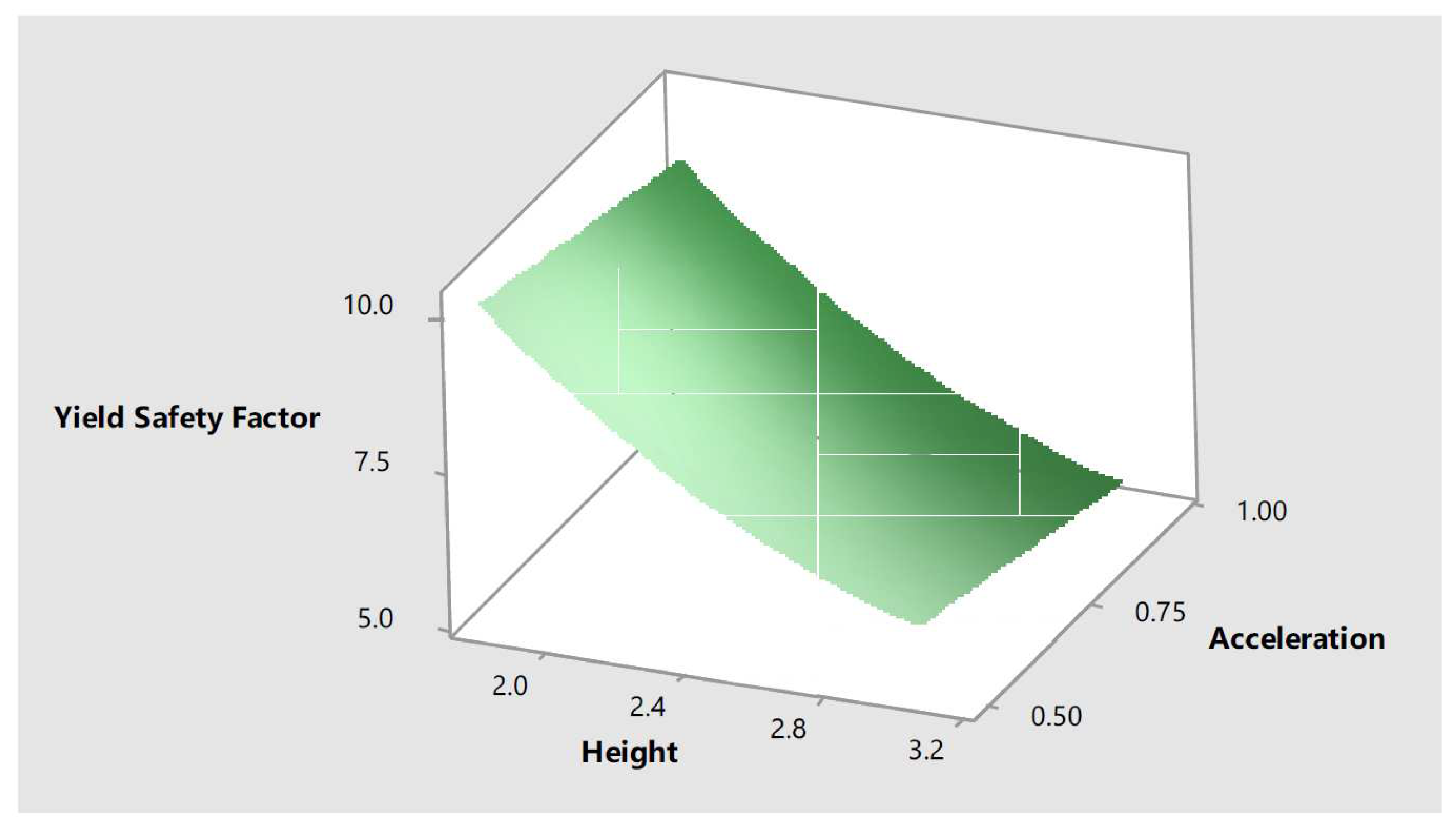
13 was also used to create the response surfaces shown in
Figure 14. This response surface shows the way in which
varies based on the values of height and acceleration. This response surfaces reflects the quadratic effect the height has in the response as initially observed in the main effect plots.
3.3. Macro elements out-of-plane analysis assuming infinite compressive strength
The design points generated with Minitab using a CCD with three factors (length, height and thickness) consisted in eight cube points, six centre cube points and six axial points. A value for the distance of the axial points equal to was used to ensure rotatability and 20 design points were generated.
The minimum value computed for
, the seismic mass multiplier, was equal to
. This value was obtained for a wall with
length,
height and
thickness (a thickness of
is outside the range of values adopted, it is automatically generated by dividing the minimum value of
by the specified value
for the axial spacing). A mass seismic multiplier of
corresponds to a lateral acceleration of
or to a PGA of
. This level of acceleration corresponds to the upper range values for low seismic hazard areas (see
Figure 2).
As previously discussed, it is expected that the higher and the thinner a wall is, the more critical it would be its safety when subjected to out-of-plane forces. This assumption is verified by the data generated with this parametric macro elements out-of-plane analysis. The non-influence of wall length in the values computed for the seismic mass multiplier, as it would be in the case of a plane strain simplified model, is explained by the fact that this parameter is not part of Equation
7.
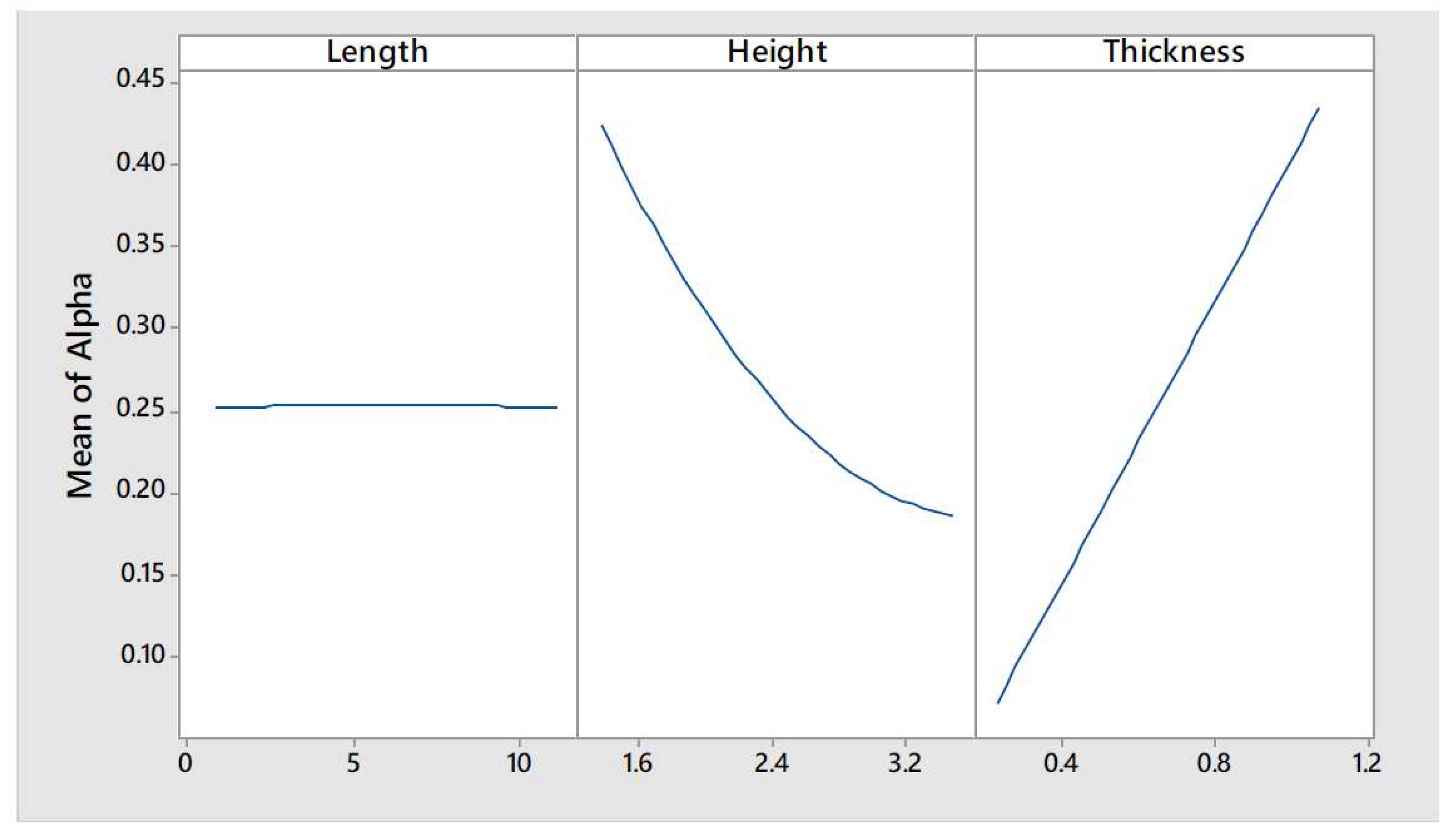
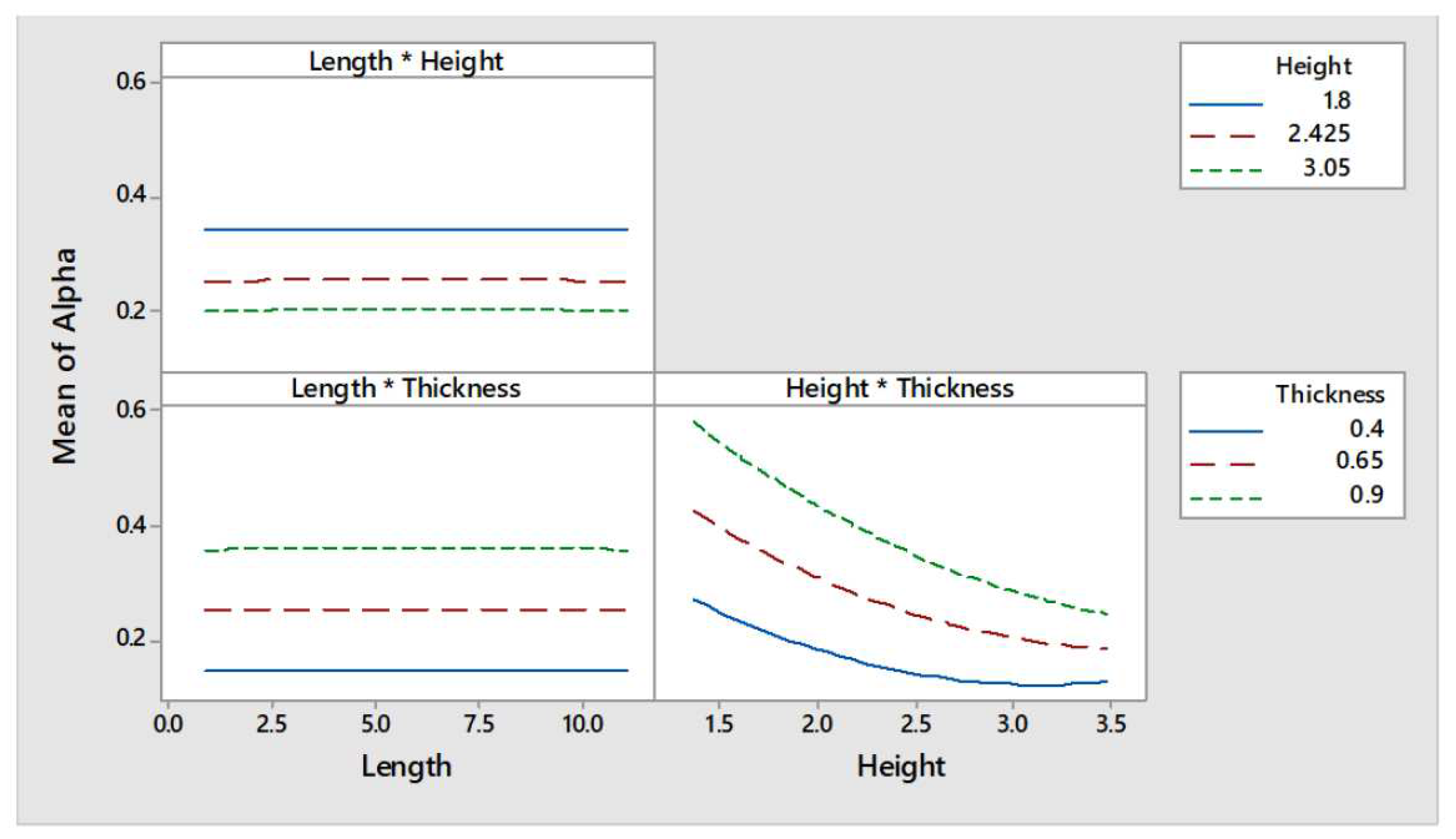
The main effect plots, see
Figure 15, showed that the value of the response,
, was quasi-constant for the different values of length explored, thus it can be concluded that
is not influenced by the length of the wall. On the other hand, the seismic mass multiplier is greatly influenced by height and thickness (see the central and right curves of
Figure 15). The seismic mass multiplier presents an inversely proportional relationship with the wall height. Moreover, this relationship seems to be non-linear. On the other hand,
presents a directly proportional relationship with the wall thickness. Furthermore, it can be observed that the interaction between parameters was negligible except for the height-thickness parameters interaction as it seems that the curves shown in the lower right corner of
Figure 16 tend to approach.
The full quadratic model was refined by removing the non-significant terms. By taking into account only those statistically significant terms the expression shown in Equation
14 was obtained. Equation
14 can be used to estimate the value of
for every combination of wall height (
in
m) and thickness (
in
m) within the range of values explored by the analysis presented in this paper. In this equation the length of the wall is not included, as its effect on the response is nonsignificant, and this is in agreement with the comment made at the beginning of the section regarding the fact that the length of the wall was expected not to influence the out-of-plane response of the wall.
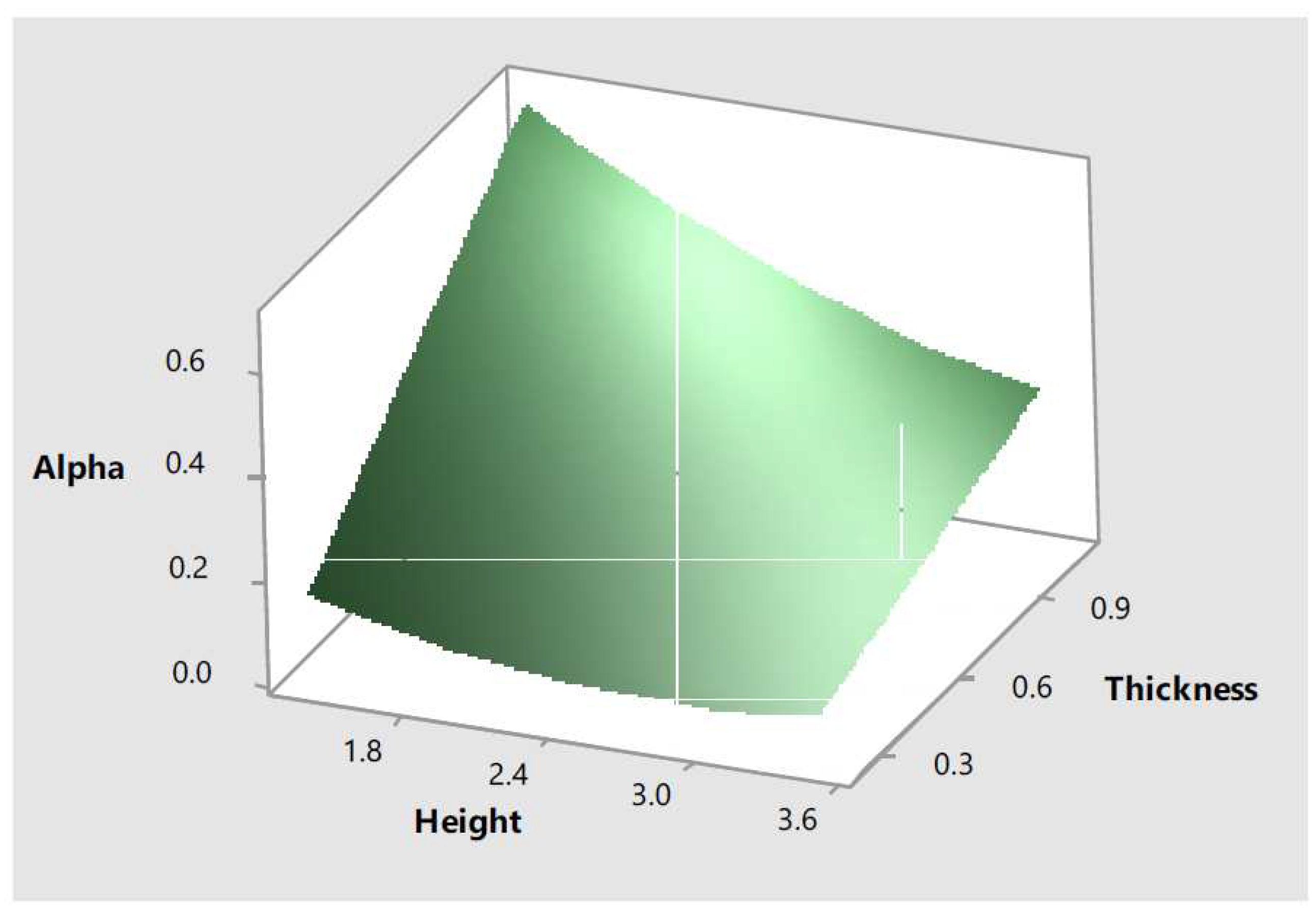
Equation
14 was also used to create the response surfaces shown in
Figure 17. The response surface shows information regarding the effect of two input parameters, wall height and thickness, in the response,
. This response surface reflects the quadratic effect the input parameters have in the response as initially observed in the main effect plots.
3.4. Macro elements out-of-plane analysis taking into account the compressive strength of the material
The compressive strength of the material was introduced as a categorical parameter with two levels representing both the yield and the ultimate compressive strength of cob (see
Table 1). Therefore, the DOE using a CCD with two continuous factors (height and thickness) and one categorical factor (compressive strength) consisted in eight cube points, ten centre cube points and eight axial points. A value for the distance of the axial points equal to
was used to ensure rotatability and 26 design points were generated.
The minimum value computed for
was equal to
. This value was obtained for two parameter combinations: a wall with
height,
thickness (a thickness of
is outside the range of values adopted, it is automatically generated by dividing the minimum value of
by the specified value
for the axial spacing) and a compressive strength of
; and for a wall with
height,
thickness and a compressive strength of
. A mass seismic multiplier of
corresponds to a lateral acceleration of
or to a PGA of
. This level of acceleration corresponds to the upper range values for low seismic hazard areas (see
Figure 2).
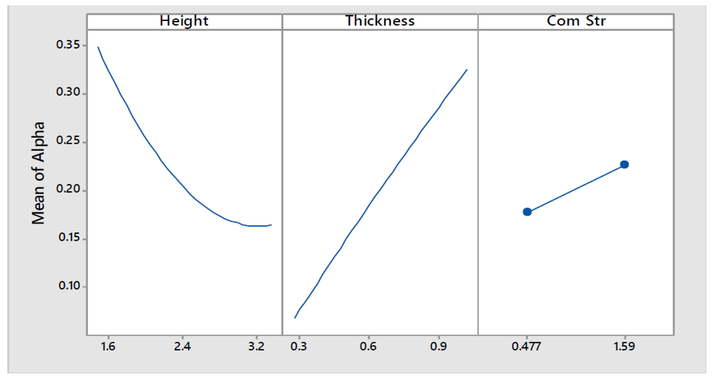
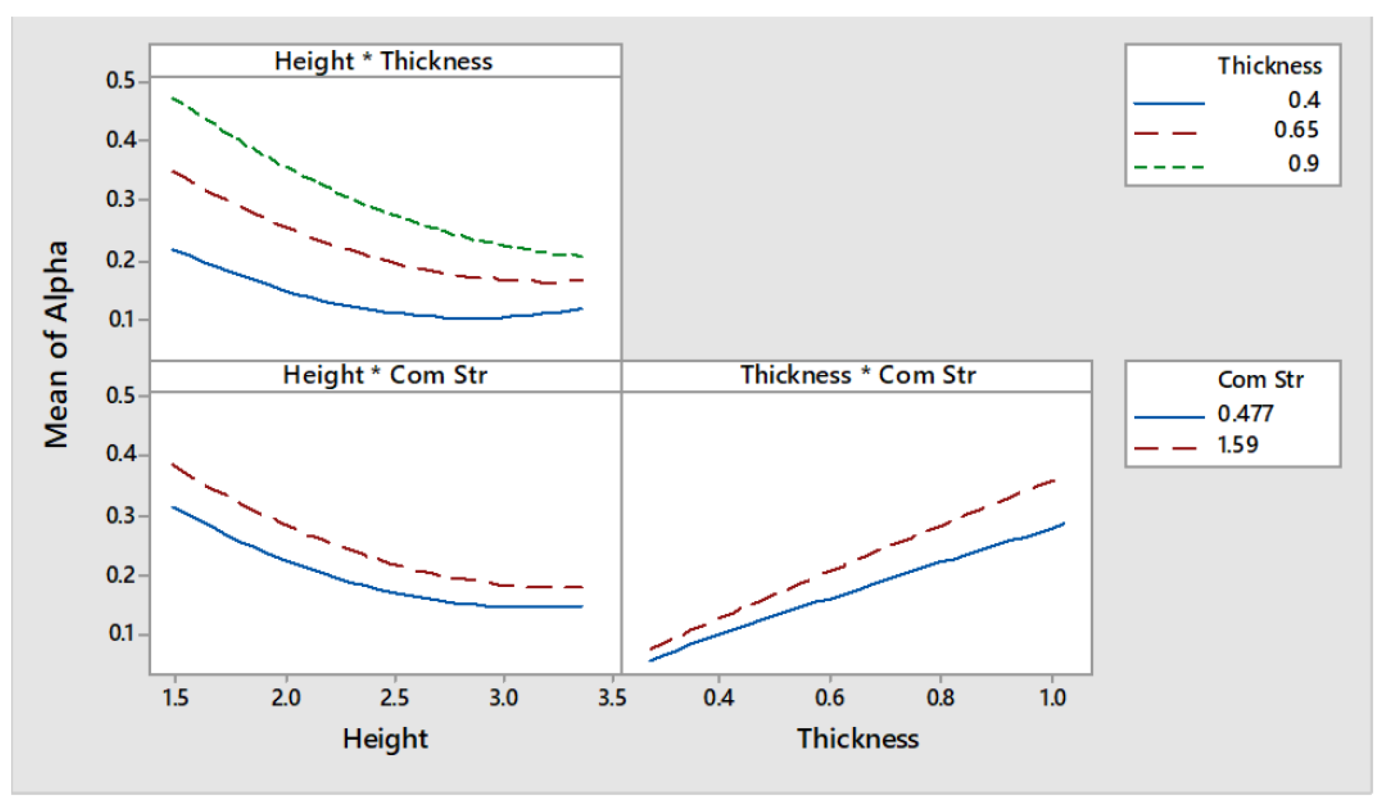
The data points generated can be better interpreted if the main and interaction effects plots, shown in
Figure 18 and
Figure 19 respectively, are analysed. The main effect plots showed that the seismic mass multiplier is greatly influenced by height and thickness (see the left and central curves of
Figure 18). The seismic mass multiplier presents an inversely proportional relationship with the wall height. Moreover, this relationship seems to be non-linear. On the other hand,
presents a directly proportional linear relationship with the wall thickness. As the higher is the compressive strength of the material, the smaller would be the value of
t, it was expected that the response would be as well influenced by this parameter. Effectively, as can be observed in the right curve of
Figure 18, a directly proportional relationship exists between cob’s compressive strength and
. Furthermore, the interactions between parameters height-thickness and thickness-compressive strength seem to be significant whereas that the height-compressive strength appears to be non-significant (see
Figure 19).
The full quadratic model was refined by removing those non-significant terms. Thus, the expression shown in Equation
15 was obtained for a compressive strength of
and the expression shown in Equation
16 was obtained for a compressive strength of
. Equation
15 and Equation
16 can be used to estimate the value of
for every combination of wall height (
in
m) and thickness (
in
m) within the range of values explored by the analysis presented in this paper based on the different compressive strengths mentioned. In these equations the length of the wall is not included, as its effect on the response is non-significant, and this is in agreement with the comment made at the beginning of the section regarding the fact that the length of the wall was expected not to influence the out-of-plane response of the wall.
If Equation
15 and Equation
16 are evaluated for a wall height of
and a thickness of
, then,
and
. This indicates that under the most adverse combination of values for the geometric parameters explored, and based on the assumptions adopted, a cob wall would have to be subjected to an acceleration of
or
so that the out-of-plane mechanism is generated if the yield compressive strength value is taken into account, and would have to subjected to an acceleration of
or
so that the out-of-plane mechanism is generated if the ultimate compressive strength value is taken into account. The decision as to what equation should be used would depend on the degree of damage that is considered acceptable for the structure. The yield of the materials could be adopted for a Serviceability Limit State (SLS) whereas that the ultimate strength of the materials would be adequate for an Ultimate Limit State (ULS) scenario.
Nevertheless, as this level of acceleration corresponds to the lower range values for a moderate seismic hazard area, and since Ireland is located in the low seismic hazard area, it can be concluded that the out-of-plane mechanism analysed would not form in Irish surviving cob walls. On the other hand, this level of acceleration can be expected to affect similar cob buildings in other regions, such as the United Kingdom and North of France, and the methodology presented in this chapter could be implemented to evaluate the safety level of those buildings.
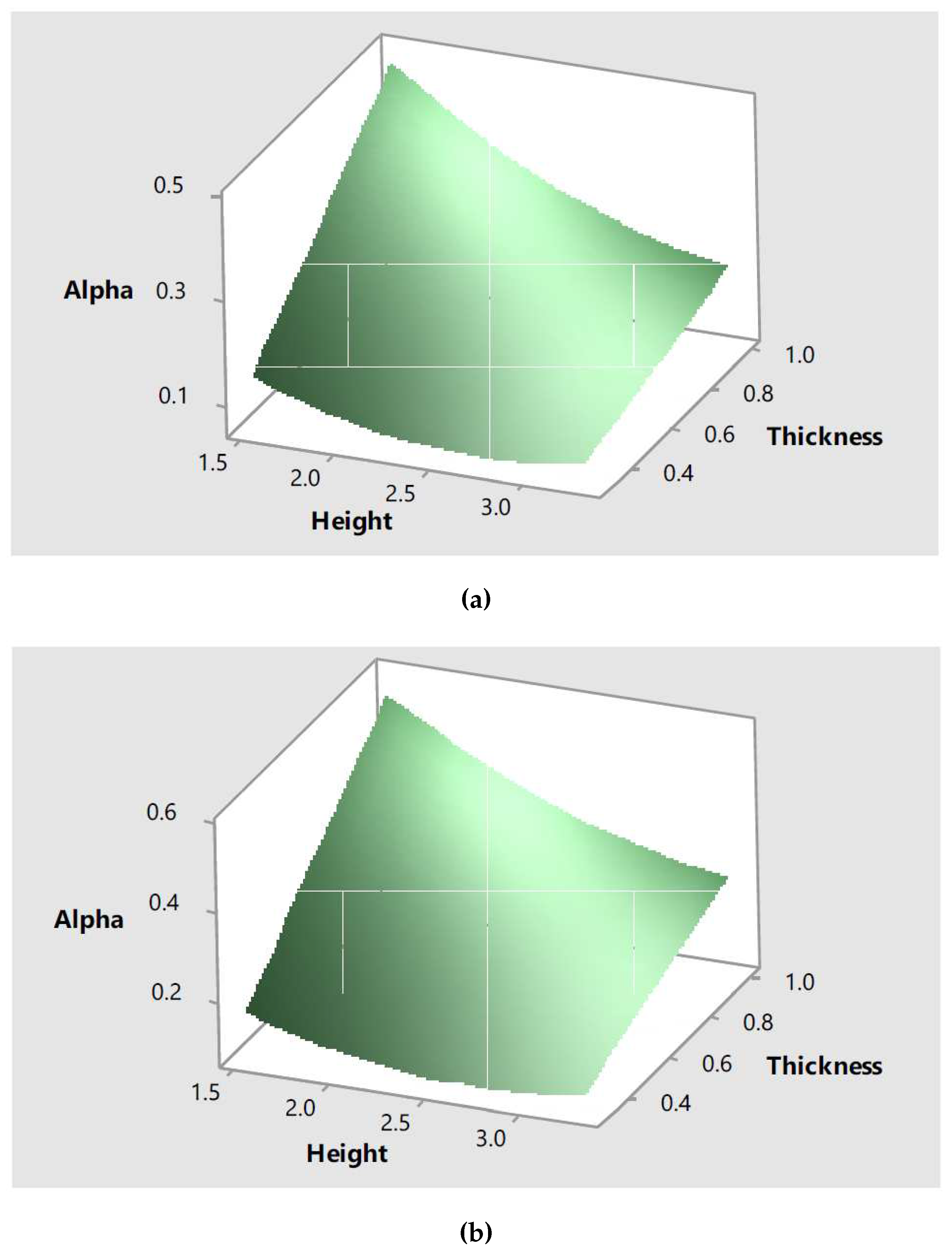
Equation
15 and Equation
16 were also used to create the response surfaces shown in
Figure 20 for values of compressive strength of
and
respectively. The response surface shows information regarding the effect of two input parameters, wall height and thickness, in the response,
. These response surfaces reflect the quadratic effect the input parameters have in the response as initially observed in the main effect plots.
3.5. Macro elements in-plane analysis assuming infinite compressive strength
The design points generated with Minitab using a CCD with three factors (length, height and thickness) consisted in eight cube points, six centre cube points and six axial points. It used a value for the distance of the axial points equal to to ensure rotatability and generated 20 design points.
The minimum value computed for is equal to . This value was obtained for a wall with length, height and thickness (a length of is outside the range of values adopted, it is automatically generated by using the axial spacing value adopted). A mass seismic multiplier of corresponds to a lateral acceleration of or to a PGA of . This level of acceleration corresponds to the upper range values for moderate seismic hazard areas.
As previously discussed, it is expected that the higher a wall is, the more critical it would be its safety when subjected to in-plane forces. The length of the wall is also expected to influence in the failure of the wall subjected to in-plane forces; bulky walls tend to fail by shear, whereas that slender walls tend to rock and fail by crushing at their base. The effect of both parameters in the wall’s response is verified by the data generated with this parametric macro elements in-plane analysis. The non-influence of wall thickness in the values computed for the seismic mass multiplier, as would be the case for a plane stress simplified problem, is explained by the fact that this parameter is not part of Equation
8.
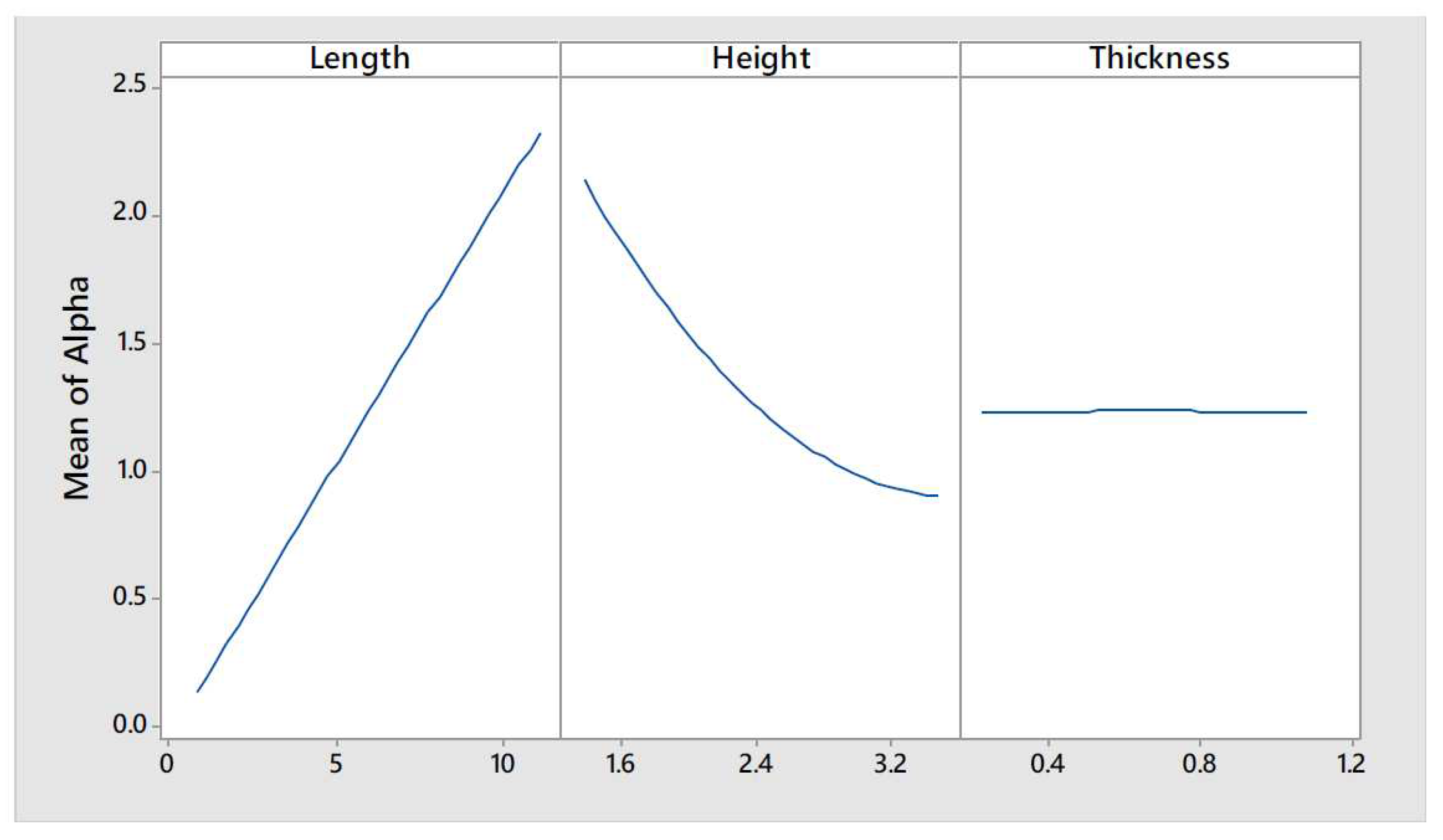
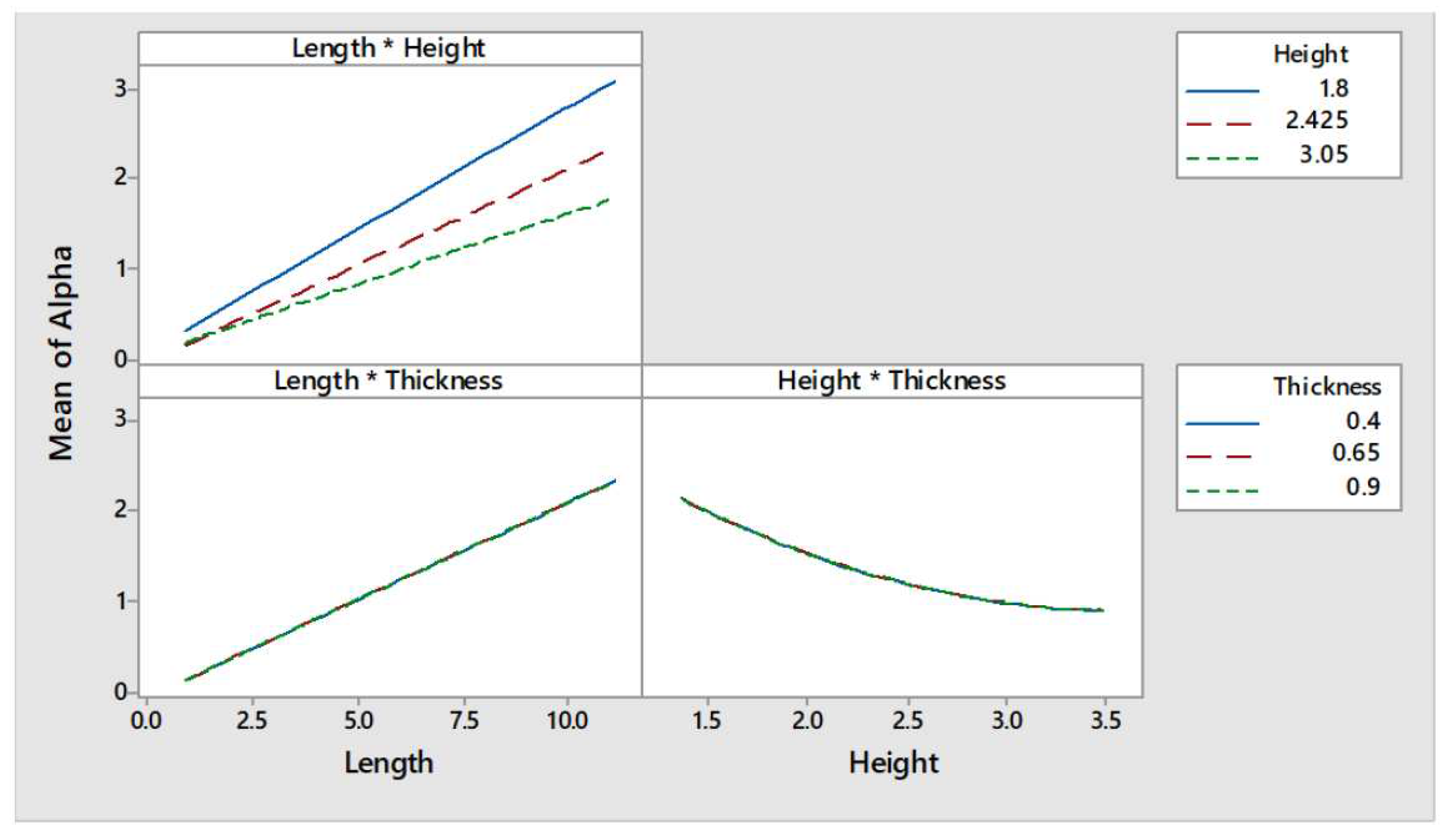
The data points generated can be better interpreted if the main and interaction effects plots, shown in
Figure 21 and
Figure 22, respectively, are analysed. The main effect plots showed that the value of the response,
, was quasi-constant for the different values of thickness explored; thus, it can be concluded that
is not influenced by the thickness of the wall. On the other hand, the seismic mass multiplier is greatly influenced by length and height (see the left and central curves of
Figure 21). The seismic mass multiplier presents an inversely proportional relationship with the wall height. Moreover, this relationship seems to be non-linear. On the other hand,
presents a directly proportional relationship with the wall length.
One of the assumptions of the macro elements limit analysis consist of the neglect of internal sliding of the element, in other words, no shear failure can be detected with this simplified model. If the length of the wall increases it is expected that its rotation, the mechanism that is being studied, would become less critical and a higher acceleration would be needed to initiate it but, in reality, this would not mean that the wall is safe from shearing failure. The lack of capability to detect that type of failure is one of the main shortcomings of the simplified model adopted in this parametric analysis. Furthermore, it can be observed that the interaction between parameters was negligible except for the length-height parameters interaction as it seems that the curves, shown in the upper left corner of
Figure 22, tend to approach at the lower values of length.
The full quadratic model was refined by removing the non-significant terms. By taking into account only those statistically significant terms the expression shown in Equation
17 was obtained. Equation
17 can be used to estimate the value of
for every combination of wall height (
in
m) and length (
in
m) within the range of values explored by the analysis presented in this thesis. In this equation the thickness of the wall is not included, as its effect on the response is non-significant, and this is in agreement with the comment made at the beginning of the section regarding the fact that the thickness of the wall was expected not to influence the in-plane response of the wall.
If Equation
17 is evaluated for a wall height of
and a length of
, then,
. This indicates that under the most adverse combination of values for the geometric parameters explored, and based on the assumptions adopted, a cob wall would have to be subjected to an acceleration of
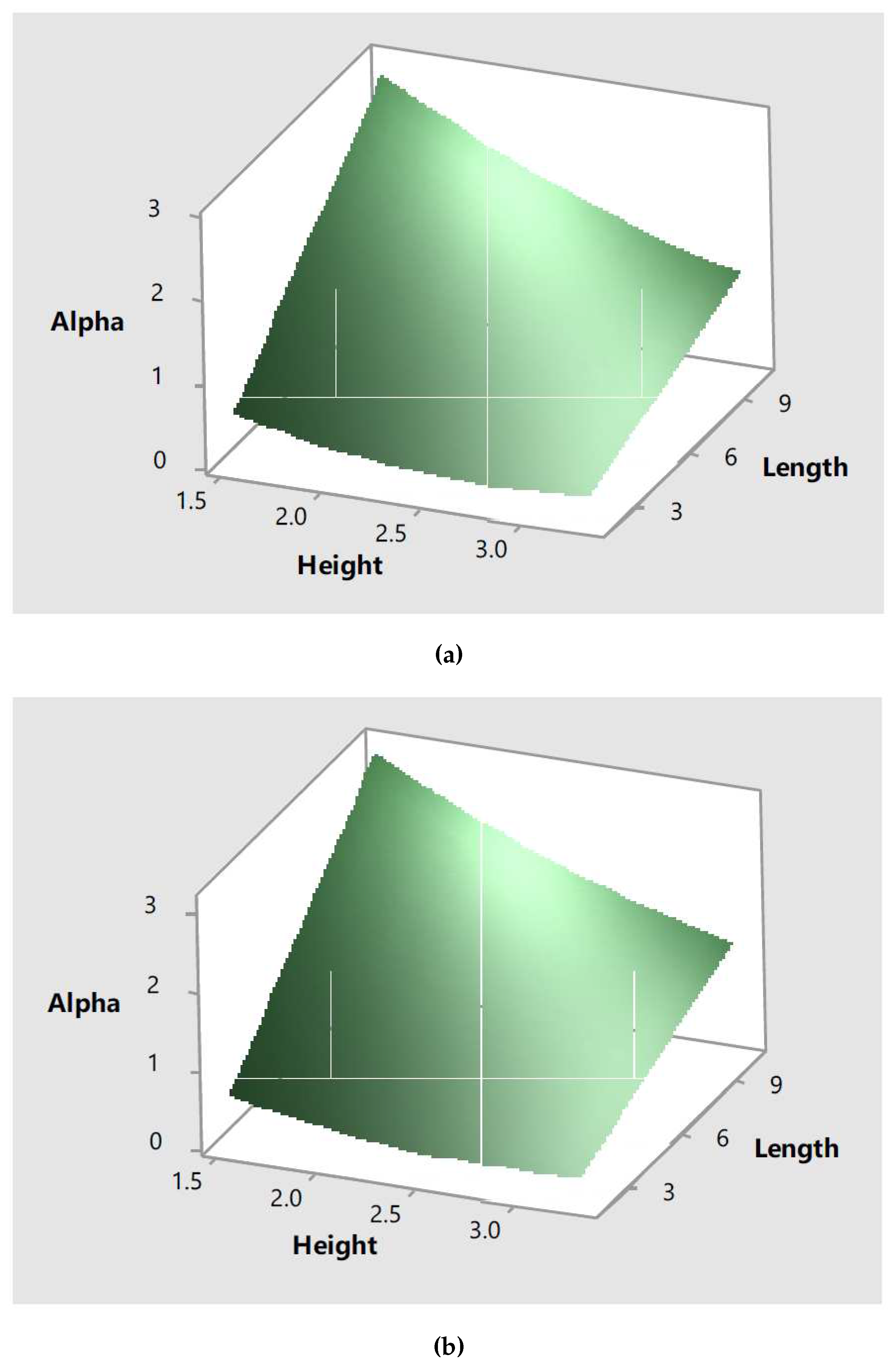
or
so that the in-plane mechanism studied is generated. This level of acceleration corresponds to the upper range values for a high seismic hazard area. As Ireland is located in the low seismic hazard area, it can be concluded that the in-plane mechanism analyzed would not form in Irish surviving cob walls.
Equation
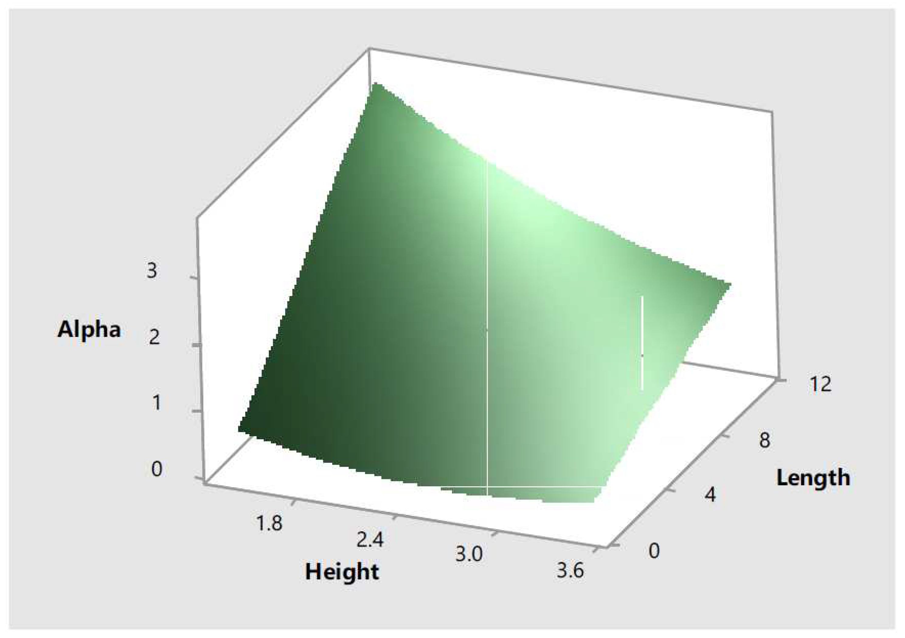
17 was also used to create the response surfaces shown in
Figure 23. The response surface shows information regarding the effect of two input parameters, wall height and length, in the response,
. These response surfaces reflect the quadratic effect the input parameters have in the response as initially observed in the main effect plots.
3.6. Macro elements in-plane analysis taking into account the compressive strength of the material
As it was observed in the parametric analysis of the previous sub-section that the thickness of the wall does not influence its in-plane response (the results of that parametric analysis confirmed the expected behaviour based on the plane stress assumption), it was decided to ignore that parameter for the macro elements in-plane analysis taking into account the compressive strength of the materials. The compressive strength of the material was introduced as a categorical parameter with two levels representing both the yield and the ultimate compressive strength of cob (see
Table 1). Therefore, the DOE using a CCD with two continuous factors (height and length) and one categorical factor (compressive strength) consisted in eight cube points, ten centre cube points and eight axial points. It used a value for the distance of the axial points equal to
to ensure rotatability and generated 26 design points.
The minimum value computed for is equal to . This value was obtained for a wall with height, length (a length of is outside the range of values adopted, it is automatically generated by using the specified axial spacing value) and a compressive strength of . A mass seismic multiplier of corresponds to a lateral acceleration of or to a PGA of . This level of acceleration corresponds to the lower range values for high seismic hazard areas.
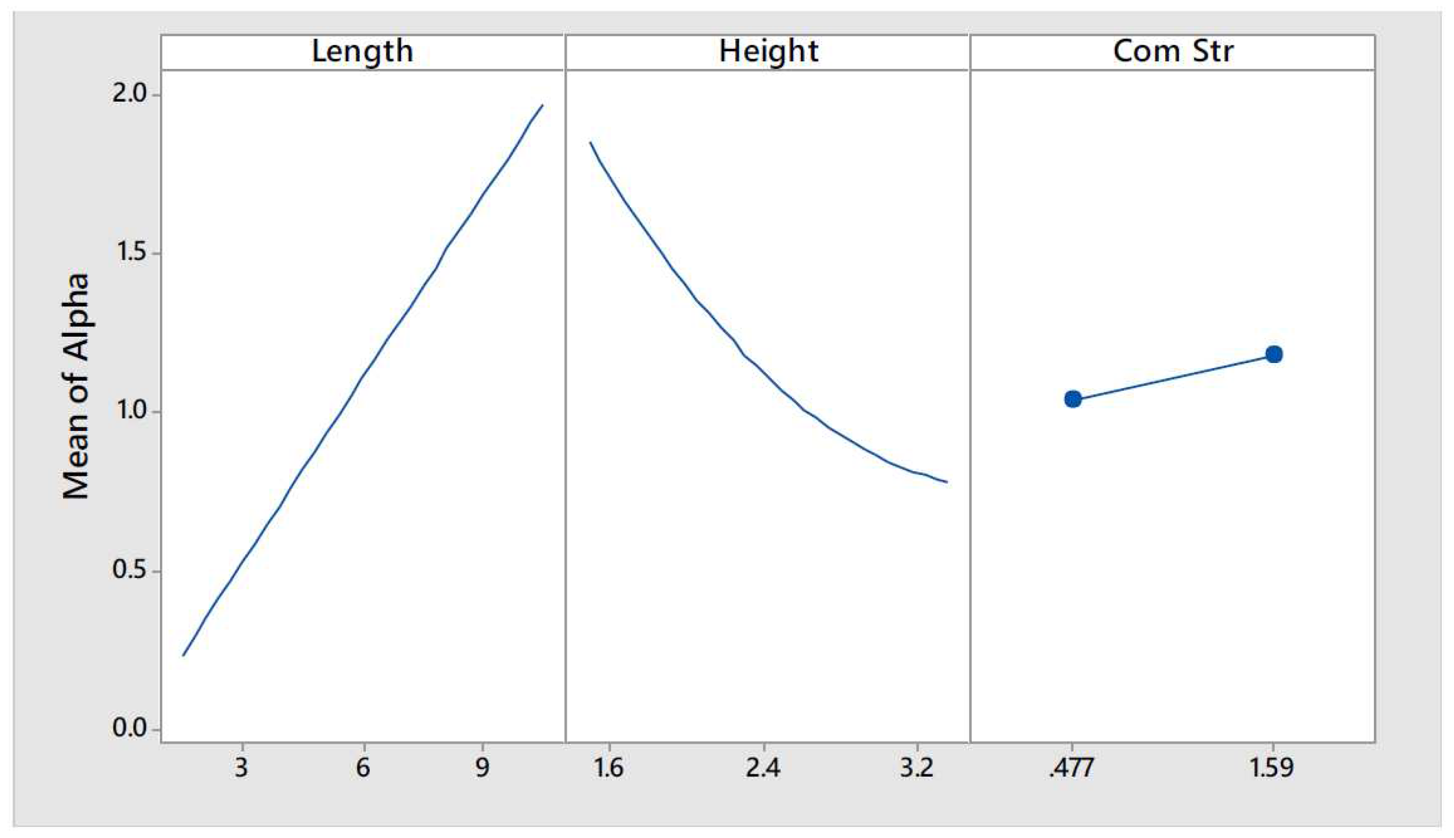
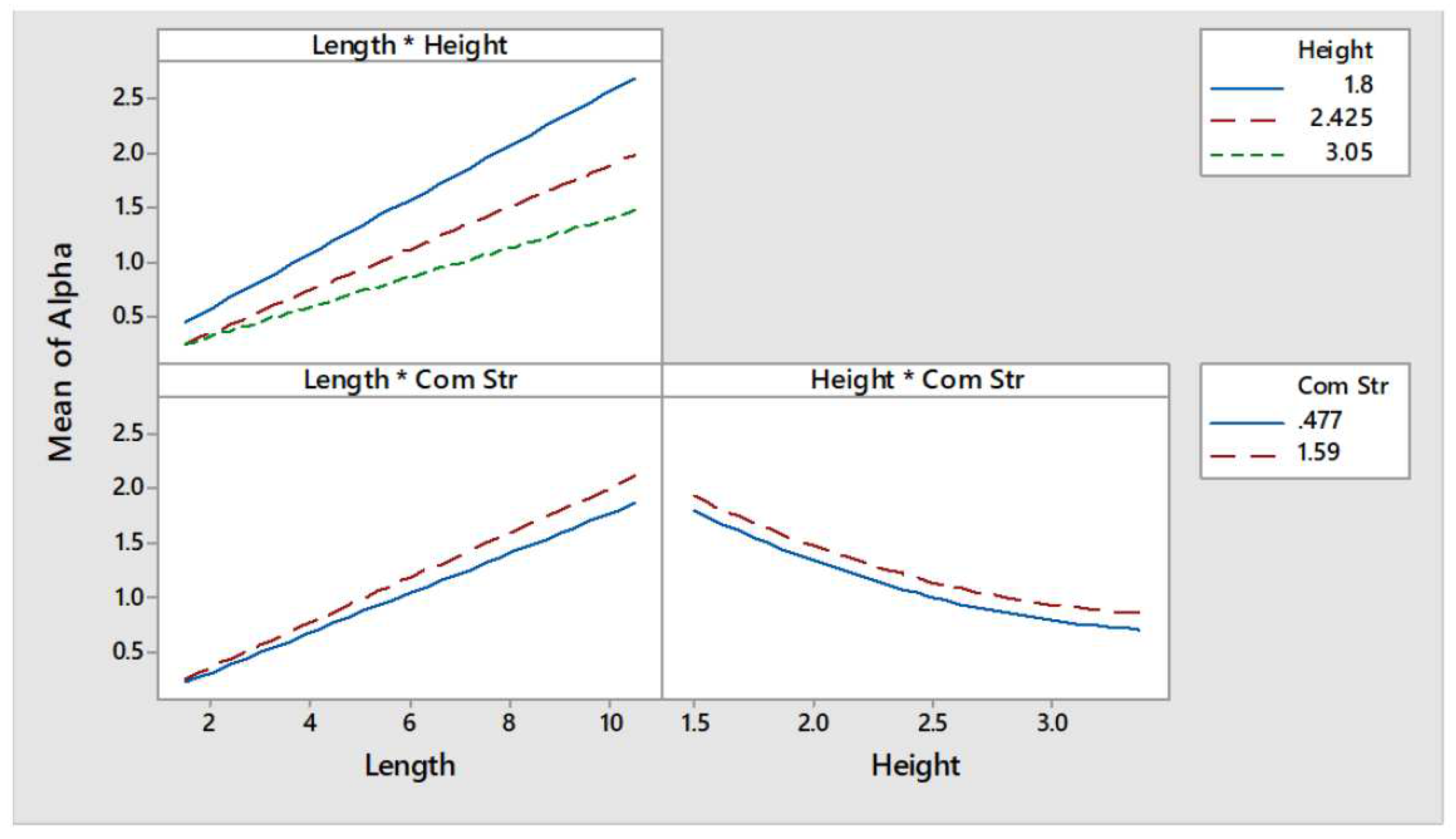
The data points generated can be better interpreted if the main and interaction effects plots, shown in
Figure 24 and
Figure 25 respectively, are analysed. The main effect plots showed that the seismic mass multiplier is greatly influenced by height and length (see the left and central curves of
Figure 24). The seismic mass multiplier presents an inversely proportional relationship with the wall height. Moreover, this relationship seems to be non-linear. On the other hand,
presents a directly proportional linear relationship with the wall length.
As the higher is the compressive strength of the material, the smaller would be the value of
t, it was expected that the response would be as well influenced by this parameter. Effectively, as can be observed in the right curve of
Figure 24, a directly proportional relationship exists between cob’s compressive strength and
. Furthermore, the interactions between parameters length-height and length-compressive strength seem to be significant whereas that the height-compressive strength appears to be non-significant (see
Figure 25).
The full quadratic model was refined by removing those non-significant terms. Thus, the expression shown in Equation
18 was obtained for a compressive strength of
and the expression shown in Equation
19 was obtained for a compressive strength of
.
If Equation
18 and Equation
19 are evaluated for a wall height of
and a length of
, then,
and
. This indicates that under the most adverse combination of values for the geometric parameters explored, and based on the assumptions adopted, a cob wall would have to be subjected to an acceleration of
or
so that the out-of-plane mechanism is generated if the yield compressive strength value is taken into account, and would have to subjected to an acceleration of
or
so that the out-of-plane mechanism is generated if the ultimate compressive strength value is taken into account. As these levels of acceleration correspond to the upper range values for a high seismic hazard area, and since Ireland is located in the low seismic hazard area, it can be concluded that the in-plane mechanism analysed would not form in Irish surviving cob walls.
Equation
18 and Equation
19 were also used to create the response surfaces shown in
Figure 26 for values of compressive strength of
and
. The response surface shows information regarding the effect of two input parameters, wall height and length, in the response,
. These response surfaces reflect the quadratic effect the input parameters have in the response as initially observed in the main effect plots.
The results of these macro elements in-plane analyses are in agreement with the results obtained with the FEM in-plane analysis. The expected negligible influence of the wall thickness on the response was confirmed by both analysis approaches. Furthermore, both analyses results demonstrated that the cob wall, even under the “worst-case scenario” assumptions adopted, would not be damaged when subjected to the range of lateral accelerations expected in Ireland.
Walls are structural elements with higher inertia in their plane than in their out-of-plane direction. Therefore, walls can resist relatively high lateral forces within their plane in comparison to lateral forces out of their plane. The parametric analyses performed and presented in this chapter are in agreement with this fact. The values presented in the last column of
Table 3 show the response values computed using the corresponding equations (and the critical values for the input parameters) for every parametric analysis performed. The safety factors obtained for the in-plane FEM analyses are higher than for the out-of-plane FEM analyses, which indicates that higher acceleration values would be required to cause damage to the wall for the in-plane than for its out-of-plane behaviour conditions studied. Similarly, higher values for the in-plane seismic mass multipliers are required to develop the in-plane mechanism than for the development of the out-of-plane mechanism according to the macro elements limit analyses results obtained.
4. Conclusions and Future Directions
The results obtained with the macro elements models are in agreement with those of the FEM analyses. The expected negligible influence of the wall length on the wall’s out-of-plane response was confirmed by both analyses approaches. Similarly, the expected negligible influence of the wall thickness on the wall’s in-plane response was also confirmed by both analyses approaches. Furthermore, both analyses results demonstrated that the cob wall, even under the “worst-case scenario” assumptions adopted, would not be damaged when subjected to the range of lateral accelerations expected.
Since the values for yield safety factors found were greater than one for all parameters combinations, it can be concluded that the linear analysis would be valid for the analysis of surviving cob walls in Ireland within the range of geometric parameters explored, at least for walls in similar conditions to the assumptions adopted. This may not hold true for decayed cob walls whose compressive strength is smaller than the values adopted based on those reported by the referenced authors or for walls with relatively high void/surface ratios.
It was identified that the possible failure modes the cob walls may develop, in case the studied parameters ranges were exceeded, would be related to the out-of-plane behaviour/mechanisms. This fact was expected beforehand and confirmed by comparing the response parameters values found for each parametric analysis performed.
The advantages of the simplified FEM linear models used in the parametric analyses presented, as per comparison to non-linear models such as those described elsewhere [
35], in this paper were:
Easy model definition (no need for calibration of parameters to describe the complex stress-strain relationship characteristic of cob);
Faster solution of the model, which allowed to run several simulations in a relatively short period of time to evaluate the design points and generate the response surfaces;
Easier interpretation of the results, based in two response parameters, yield safety factor, , and ultimate safety factor, .
Based on the results obtained with both simplified analyses traditional cob walls in Ireland could be described structurally as very robust. It was observed that relatively high acceleration values, unlikely to happen in a low seismic hazard region such as Ireland, would be needed to start the collapse mechanisms studied or cause yielding in typical vernacular cob walls. Due to the characteristics of the vernacular architecture typologies in the island (single story buildings with regular rectangular plans), low seismicity hazard levels and relatively thick walls, needed in principle for construction purposes, it can be concluded that cob walls would very rarely fail under the seismic loads that they may normally be subjected to. Proof of this fact are the many remaining cob buildings which, providing they had been adequately protected against rain and raising damp, have survived for hundreds of years in a relatively good state.
The equations generated with the refined regression models, based solely in the geometry of the walls and acceleration values, can be used by practitioners as a first approach to estimate the safety levels of existing cob buildings in Ireland as well as in other countries where buildings with similar characteristics exists, such as in the United Kingdom and North of France. Nevertheless, it must be borne in mind that the assumptions adopted and the analyses performed to obtain them are of conservative nature. If their application results in the design of an over invasive intervention it is advisable to carry out a more sophisticated analysis in order to try to preserve, as much as possible, the value of the structure and its original fabric.
The logical line of extension for the results presented in this thesis would consist on the study of different conditions that would affect existing cob walls responses, i.e. voids, lateral and top movement restrictions, wind load, etc. Furthermore, the simple methodology adopted to generate the parametric analysis presented in this thesis could be also used as part of a more complex seismic vulnerability analysis in countries located in moderate or high seismic hazard areas as it provides an efficient and relatively fast way to obtain an estimate of the building structural response.
Funding
The APC was funded by Oslo Metropolitan University.
Data Availability Statement
The data presented in this study are available on request from the corresponding author.
Conflicts of Interest
The author declares no conflict of interest.
Abbreviations
| FEM |
Finite Element Method |
| NIAH |
National Inventory of Architectural Heritage |
| SHARE |
Seismic Hazard Harmonization in Europe |
| PGA |
Peak Ground Acceleration |
| NIKER |
Earthquake–Induced Risk |
| DOE |
Design Of Experiments |
| CCD |
Central Composite Design |
| ANOVA |
Analysis of Variance |
References
- Belarbi, Y.E.; Sawadogo, M.; Poullain, P.; Issaadi, N.; Hamami, A.E.A.; Bonnet, S.; Belarbi, R. Experimental Characterization of Raw Earth Properties for Modeling Their Hygrothermal Behavior. Buildings 2022, 12. [Google Scholar] [CrossRef]
- Affan, H.; Touati, K.; Benzaama, M.H.; Chateigner, D.; El Mendili, Y. Earth-Based Building Incorporating Sargassum muticum Seaweed: Mechanical and Hygrothermal Performances. Buildings 2023, 13. [Google Scholar] [CrossRef]
- Spennemann, D.H.R. Earth to Earth: Patterns of Environmental Decay Affecting Modern Pise Walls. Buildings 2022, 12. [Google Scholar] [CrossRef]
- Tan, J.; Liang, J.; Wan, L.; Jiang, B. Influence of Non-Constant Hygrothermal Parameters on Heat and Moisture Transfer in Rammed Earth Walls. Buildings 2022, 12. [Google Scholar] [CrossRef]
- Alrashed, F.; Asif, M.; Burek, S. The Role of Vernacular Construction Techniques and Materials for Developing Zero-Energy Homes in Various Desert Climates. Buildings 2017, 7. [Google Scholar] [CrossRef]
- Li, S.; Wang, M.; Shen, P.; Cui, X.; Bu, L.; Wei, R.; Zhang, L.; Wu, C. Energy Saving and Thermal Comfort Performance of Passive Retrofitting Measures for Traditional Rammed Earth House in Lingnan, China. Buildings 2022, 12. [Google Scholar] [CrossRef]
- Jiménez Rios, A.; O’Dwyer, D. Numerical Modeling of Cob’s Nonlinear Monotonic Structural Behavior. International Journal of Computational Methods 2020, 17, 1940013. [Google Scholar] [CrossRef]
- Miccoli, L.; Müller, U.; Fontana, P. Mechanical behaviour of earthen materials: A comparison between earth block masonry, rammed earth and cob. Construction and Building Materials 2014, 61, 327–339. [Google Scholar] [CrossRef]
- Matos, A.M.; Varum, H. Self-Compacting Earth-Based Composites: Mixture Design and Multi-Performance Characterisation. Buildings 2022, 12. [Google Scholar] [CrossRef]
- Jiménez Rios, A.; O’Dwyer, D. Earthen buildings in Ireland. CRC Press/Balkema, 2018, Vol. 2, p. 787 – 794. Cited by: 1; All Open Access, Green Open Access. [CrossRef]
- Ahmadi, S.S.; Karanikoloudis, G.; Mendes, N.; Illambas, R.; Lourenco, P.B. Appraising the Seismic Response of a Retrofitted Adobe Historic Structure, the Role of Modal Updating and Advanced Computations. Buildings 2022, 12. [Google Scholar] [CrossRef]
- Jiménez Rios, A.; O’Dwyer, D. Experimental validation for the application of the flat jack test in cob walls. Construction and Building Materials 2020, 254, 119148. [Google Scholar] [CrossRef]
- Young, A. A Tour in Ireland: With General Observations on the Present State of that Kingdom: Made in the Years 1776, 1777, and 1778. And Brought Down to the End of 1779; Number v. 1 in A Tour in Ireland, G. Bonham, 1780.
- Gailey, A. Rural Houses of the North of Ireland; Donald, 1984.
- Pfeiffer, W. Irish Cottages; Random House Value Publishing, 1992.
- Keefe, L.; Trust, D.H.B. The Cob Buildings of Devon: Repair and maintenance; Number v. 2, Devon Historic Buildings Trust, 1993.
- O’Reilly, B. Hearth and home: the vernacular house in Ireland from c. 1800. Proceedings of the Royal Irish Academy. Section C: Archaeology, Celtic Studies, History, Linguistics, Literature 2011, 111C, 193–215. [Google Scholar] [CrossRef]
- Webster, F.A. Application of stability-based retrofit measures on some historic and older adobe buildings in California. Proceedings of the Getty Seismic Adobe Project 2006 Colloquium, Getty Center, Los Angeles, April 11–13, 2006.
- Giardini, D.; Wössner, J.; Danciu, L. Mapping Europe’s Seismic Hazard. Eos, Transactions American Geophysical Union 2014, 95, 261–262. [Google Scholar] [CrossRef]
- Chopra, A. Dynamics of Structures; Prentice-Hall international series in civil engineering and engineering mechanics, Pearson Education, 2007.
- ANSYS Inc. ANSYS Academic Research Mechanical, 2017.
- Roca, P.; Pelà, L.; Molins, C. The Iscarsah Guidelines on the Analysis, Conservation and Structural Restoration of Architectural Heritage. 12th International Conference on Structural Analysis of Historical Constructions (SAHC), 2021.
- Janicki, D. Typical weights of building materials, 2023.
- ANSYS Inc. ANSYS Mechanical APDL Element Reference; 2017.
- ANSYS Inc. ANSYS Mechanical User’s Guide; 2017.
- Miccoli, L.; Silva, R.A.; Oliveira, D.V.; Müller, U. Static Behavior of Cob: Experimental Testing and Finite-Element Modeling. Journal of Materials in Civil Engineering 2019, 31, 04019021. [Google Scholar] [CrossRef]
- Jiménez Rios, A.; Pingaro, M.; Reccia, E.; Trovalusci, P. Statistical Assessment of In-Plane Masonry Panels Using Limit Analysis with Sliding Mechanism. Journal of Engineering Mechanics 2022, 148, 04021158. [Google Scholar] [CrossRef]
- Jiménez Rios, A.; Nela, B.; Pingaro, M.; Reccia, E.; Trovalusci, P. Rotation and sliding collapse mechanisms for in plane masonry pointed arches: statistical parametric assessment. Engineering Structures 2022, 262, 114338. [Google Scholar] [CrossRef]
- Valluzzi, M.R.; Munari, M.; Modena, C.; Binda, L.; Cardani, G.; Saisi, A. Multilevel Approach to the Vulnerability Analysis of Historic Buildings in Seismic Areas Part 2: Analytical Interpretation of Mechanisms for Vulnerability Analysis and Structural Improvement / Ansatz zur Analyse der Empfindlichkeit historischer Gebäude in Erdbeben gefährdeten Zonen auf mehreren Ebenen; Teil 2: Analytische Interpretation der Mechanismen für eine Empfindlichkeitsanalyse und für das Ertüchtigen von Tragwerken. Restoration of Buildings and Monuments 2007, 13, 427–442. [Google Scholar] [CrossRef]
- The MathWorks Inc. MATLAB version: 9.13.0 (R2022b), 2022.
- ANSYS Inc. ANSYS Design Exploration User’s Guide; 2017.
- Minitab, LLC. Minitab, 2017.
- Minitab, LLC. MINITAB User’s guide 2: data analysis and quality tools, 2017.
- Montgomery, D.C.; Runger, G.C. Applied statistics and probability for engineers; John wiley & sons, 2020.
- Jiménez Rios, A.; Ruiz-Capel, S.; Plevris, V.; Nogal, M. Computational methods applied to earthen historical structures. Frontiers in Built Environment 2023, 9. [Google Scholar] [CrossRef]
Figure 1.
Multilevel approach for the simplified analysis of cob walls.
Figure 1.
Multilevel approach for the simplified analysis of cob walls.
Figure 2.
PGA (in
g) map of Europe for a
exceedance probability in 50 years (adapted from [
19]).
Figure 2.
PGA (in
g) map of Europe for a
exceedance probability in 50 years (adapted from [
19]).
Figure 3.
Vertical cracks in a cob building located in County Kildare, Ireland (pay special attention to the cracks at the corners running all along the wall’s height).
Figure 3.
Vertical cracks in a cob building located in County Kildare, Ireland (pay special attention to the cracks at the corners running all along the wall’s height).
Figure 4.
FEM model setup for (a) in-plane analysis and (b) out-of-plane analysis.
Figure 4.
FEM model setup for (a) in-plane analysis and (b) out-of-plane analysis.
Figure 5.
In-plane typical damages caused by horizontal loads; (a) rocking, (b) sliding shear and (c) diagonal cracking.
Figure 5.
In-plane typical damages caused by horizontal loads; (a) rocking, (b) sliding shear and (c) diagonal cracking.
Figure 6.
Out-of-plane typical damages observed in cob walls.
Figure 6.
Out-of-plane typical damages observed in cob walls.
Figure 7.
Out-of-plane mechanisms (a) assuming infinite compressive strength and (b) accounting for the compressive strength of the material, .
Figure 7.
Out-of-plane mechanisms (a) assuming infinite compressive strength and (b) accounting for the compressive strength of the material, .
Figure 8.
In-plane mechanisms (a) assuming infinite compressive strength and (b) accounting for the compressive strength of the material, .
Figure 8.
In-plane mechanisms (a) assuming infinite compressive strength and (b) accounting for the compressive strength of the material, .
Figure 9.
Main effects plots for the out-of-plane FEM model.
Figure 9.
Main effects plots for the out-of-plane FEM model.
Figure 10.
Interaction effects plots for the out-of-plane FEM model.
Figure 10.
Interaction effects plots for the out-of-plane FEM model.
Figure 11.
Response surfaces for for the out-of-plane FEM model.
Figure 11.
Response surfaces for for the out-of-plane FEM model.
Figure 12.
Main effects plots for the in-plane FEM model.
Figure 12.
Main effects plots for the in-plane FEM model.
Figure 13.
Interaction effects plots for the in-plane FEM model.
Figure 13.
Interaction effects plots for the in-plane FEM model.
Figure 14.
Response surfaces for for the in-plane FEM model.
Figure 14.
Response surfaces for for the in-plane FEM model.
Figure 15.
Main effects plots for the out-of-plane mechanism assuming infinite compressive strength.
Figure 15.
Main effects plots for the out-of-plane mechanism assuming infinite compressive strength.
Figure 16.
Interaction plots for the out-of-plane mechanism assuming infinite compressive strength.
Figure 16.
Interaction plots for the out-of-plane mechanism assuming infinite compressive strength.
Figure 17.
Response surface for the out-of-plane mechanism assuming infinite compressive strength.
Figure 17.
Response surface for the out-of-plane mechanism assuming infinite compressive strength.
Figure 18.
Main effects plots for the out-of-plane mechanism accounting for the compressive strength of cob.
Figure 18.
Main effects plots for the out-of-plane mechanism accounting for the compressive strength of cob.
Figure 19.
Interaction plots for the out-of-plane mechanism accounting for the compressive strength of cob.
Figure 19.
Interaction plots for the out-of-plane mechanism accounting for the compressive strength of cob.
Figure 20.
Response surface for the out-of-plane mechanism for a compressive strength of cob of (a) and (b) .
Figure 20.
Response surface for the out-of-plane mechanism for a compressive strength of cob of (a) and (b) .
Figure 21.
Main effects plots for the in-plane mechanism assuming infinite compressive strength.
Figure 21.
Main effects plots for the in-plane mechanism assuming infinite compressive strength.
Figure 22.
Interaction plots for the in-plane mechanism assuming infinite compressive strength.
Figure 22.
Interaction plots for the in-plane mechanism assuming infinite compressive strength.
Figure 23.
Response surface for the in-plane mechanism assuming infinite compressive strength.
Figure 23.
Response surface for the in-plane mechanism assuming infinite compressive strength.
Figure 24.
Main effects plots for the in-plane mechanism accounting for the compressive strength of cob.
Figure 24.
Main effects plots for the in-plane mechanism accounting for the compressive strength of cob.
Figure 25.
Interaction plots for the in-plane mechanism accounting for the compressive strength of cob.
Figure 25.
Interaction plots for the in-plane mechanism accounting for the compressive strength of cob.
Figure 26.
Response surface for the in-plane mechanism for a compressive strength of cob of (a) and (b) .
Figure 26.
Response surface for the in-plane mechanism for a compressive strength of cob of (a) and (b) .
Table 1.
Cob mechanical properties.
Table 1.
Cob mechanical properties.
| Property |
Value |
| Density () |
1475 |
| Young’s modulus () |
|
| Poisson’s ratio (-) |
|
| Tension yield strenght () |
|
| Compression yield strength () |
|
| Tension ultimate strength () |
|
| Compression ultimate strength () |
|
Table 2.
Cob walls geometric parameters values.
Table 2.
Cob walls geometric parameters values.
| Parameter |
Minimum value |
Maximum value |
| Length (m) |
|
|
| Height (m) |
|
|
| Thickness (m) |
|
|
Table 3.
Critical response values obtained with the different parametric analysis performed.
Table 3.
Critical response values obtained with the different parametric analysis performed.
| Analysis type |
Mechanism |
Response |
Value |
| FEM |
In-plane |
|
|
| |
|
|
|
| |
Out-of-plane |
|
|
| |
|
|
|
| Limit Analysis |
In-plane |
|
|
| |
|
|
|
| |
|
|
|
| |
Out-of-plane |
|
|
| |
|
|
|
| |
|
|
|
|
Disclaimer/Publisher’s Note: The statements, opinions and data contained in all publications are solely those of the individual author(s) and contributor(s) and not of MDPI and/or the editor(s). MDPI and/or the editor(s) disclaim responsibility for any injury to people or property resulting from any ideas, methods, instructions or products referred to in the content. |
© 2023 by the authors. Licensee MDPI, Basel, Switzerland. This article is an open access article distributed under the terms and conditions of the Creative Commons Attribution (CC BY) license (http://creativecommons.org/licenses/by/4.0/).
