1. Introduction
A typical surface alloy (SA) is a coating characterized by the highest level of adhesion to a substrate due to the liquid-phase fusion with its top layer. The fundamental difference between SAs and conventional PVD coatings is the presence of an interlayer (or transition layer) between the coating and the substrate in the first case. In the transition layer, concentrations of the coating elements gradually decrease from their core compositions down to zero, while contents of the substrate atoms, on the contrary, increases up to 100%. Most physical properties of the intermediate layer change smoothly from the coating values to those inherent in the substrate material. In particular, an in-depth gradient of the thermal expansion coefficient on the “substrate – SA coating” boundary is one-to-two orders of magnitude lower than that for the “substrate – PVD coating” boundary. Accordingly, thermal stresses are significantly lower upon heating in this case. For SAs, the transition layer formation reduces the likelihood of their delamination from substrates compared with similar PVD coatings. Nowadays, SAs are formed on different coating – substrate systems for various applications [
1,
2,
3,
4].
It is known that diffusion of zirconium to the surface occurs mainly along the grain boundaries of the coating, especially in the case of a columnar or porous coating microstructure [
5]. At the same time, oxygen penetrates to the zirconium substrate along the coating grain boundaries as well. This interdiffusion process, as a rule, results in the formation of an intergranular zirconium-oxide grid, facilitating the transport of both oxygen and zirconium and increasing the oxidation rate.
In this study, it was assumed that a SA had to act as a diffusion barrier (or a protective coating resistant to high temperature oxidation) for a zirconium substrate. The SA had to prevent the diffusion of oxygen from an environment into the substrate. This task is important from viewpoint of the development strategies for accident-tolerant fuels for nuclear reactors in order to reduce the risk of the zirconium–vapor reactions.
2. Materials and Methods
Zirconium samples with dimensions of 15×15×2 mm and a purity of 99.95 wt.% were used as substrates. Initially, Fe
69Cr
20Al
11 (at.%) films with a thickness of 1 μm were deposited by magnetron sputtering. Then, they were mixed in a liquid phase with the substrates by LEHCEB processing (4 pulses with energy densities of 2.4 or 4.6 J/cm
2, according to
Table 1). The used equipment, its parameters, and mode designation were described in more detail in [
2,
6].
Microstructural examinations of thin foils in the cross-section geometry were carried out by transmission electron microscopy (TEM). Their chemical compositions were assessed with an EDS analyzer.
In-situ synchrotron X-ray diffraction studies were carried out at the Precision Diffractometry Station of the Siberian Center for Synchrotron and Terahertz Radiation. X-ray patterns were obtained in the grazing incidence mode at an angle of 5° during linear heating of the samples with SAs from 30 up to 1543 K at a rate of 15 K/min in vacuum.
Computer simulation of the dynamics of temperature fields under irradiation with PEBs has been carried out using the ‘HEATPACK-1.0’ software package, described in [
3,
6].
3. Results and Discussion
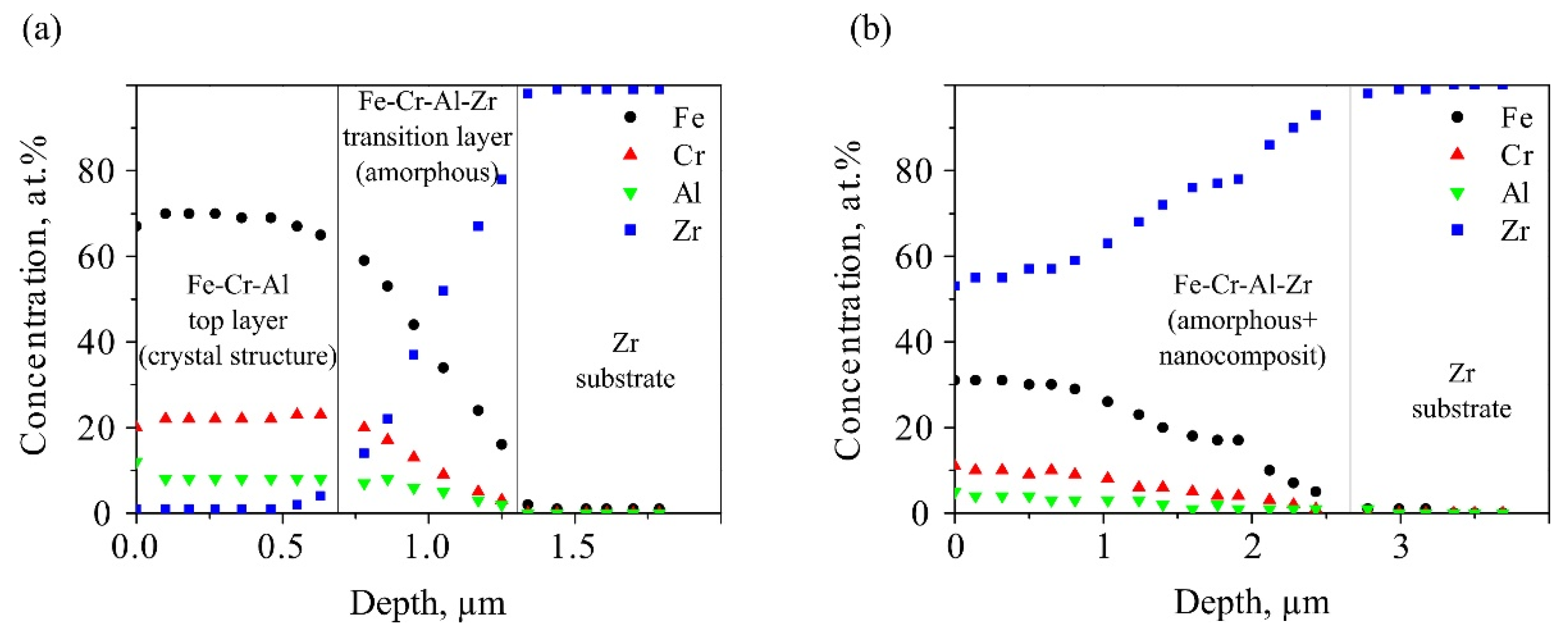
Figure 1 shows in-depth element distributions on the samples after LEHCEB processing. Their nature was fundamentally different for modes (1) and (2). For mode (1), two layers were observed: first of a given elemental composition and second - a transition layer located at depths of 0–0.7 and 0.7–1.3 µm, respectively. In the first layer, concentrations of the SA elements, namely, iron, chromium and aluminum, remained constant and coincided with the concentrations of elements in the pre-deposited film, while the zirconium content was close to zero. The second layer was transitional, in which the zirconium content increased from 0 up to 100%, while the concentrations of the coating elements, vice versa, reduced to zero.
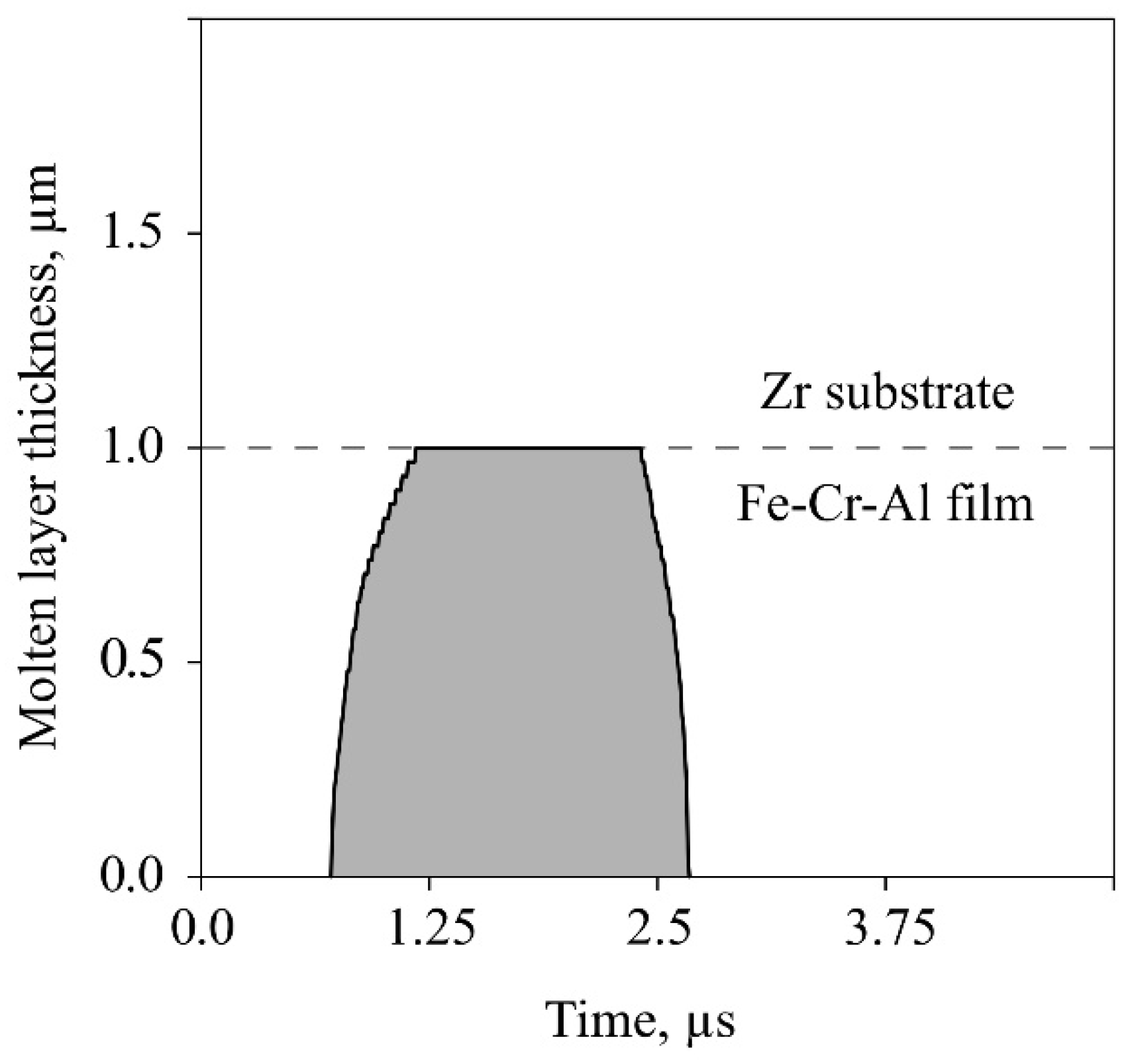
For mode (1), it followed from its in-depth element distribution that the molten layer thickness had been about 1.3 μm upon LEHCEB processing, since the zirconium content was less than 100% down to this distance from the sample surface. The calculations give very close result (see
Figure 2) which is, nevertheless, about 30% less. The difference between the calculations and experiments may be explained by the effect of the energy density dispersion from pulse to pulse [
6]. According to the calculation results, the duration of melt existence had been 1.9µs. During this period, zirconium had diffused into the liquid phase from a depth of 1.0 up to 0.5 µm, but without reaching the surface. Accordingly, the zirconium linear diffusion rate could be estimated as ≈0.26 m/s under these nonequilibrium conditions. The iron diffusion rate into the zirconium substrate was approximately the same.
For mode (2), the SA formation process had been completely different upon LEHCEB processing. A single layer up to 3 µm thick was found at the sample surface, the composition of which varied significantly from that of the pre-deposited film. Compared to the SA formed according to mode (1), which composition was about Fe69Cr20Al11 (at.%), the contents of all constituent elements decreased by about a factor of two for mode (2), characterized by intense melting. At the same time, a great zirconium concentration (more than 50 at.%) was observed on the sample surface, which had diffused in the liquid phase. Accordingly, the SA had been formed not only from the elements of the pre-deposited film, but also from the substrate material, representing the Fe-Cr-Al-Zr system.
According to the Fe-Zr state diagram, the iron partition coefficient in the zirconium concentration range of 35–70 at.% was
where Cs and Cl were the iron concentrations in the solid and liquid phases, respectively. It followed from the above fact that, at the crystallization front of the binary Fe-Zr molten mixture, not iron atoms but zirconium ones had been displaced to the sample surface, which was observed experimentally.
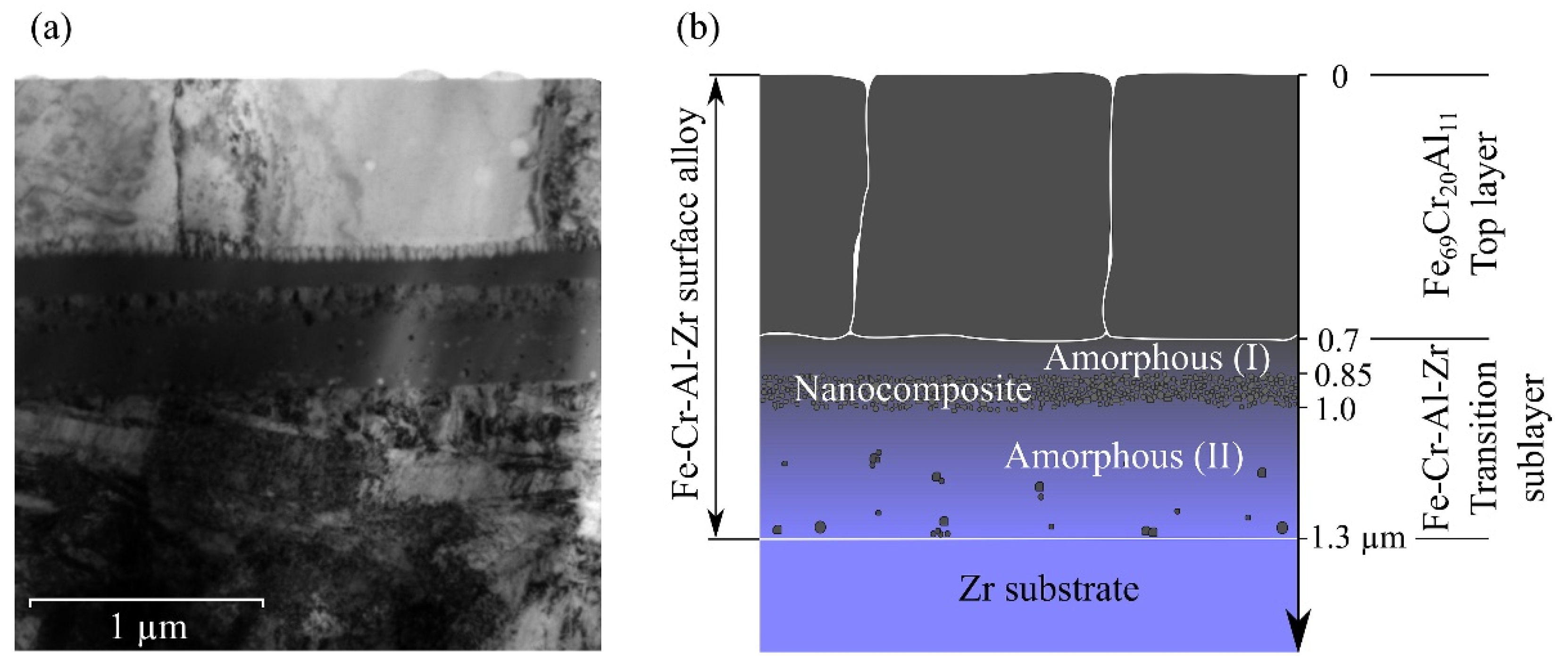
Figure 3 shows a bright-field TEM image and a scheme of the cross-section of the Fe-Cr-Al-Zr SA formed on the zirconium surface using mode (1). The top layer ≈0.7 µm thick consisted of rectangular grains with thicknesses of about 0.6 µm and widths of 0.5–0.8 µm, oriented perpendicular to the surface.
The second transition layer ≈0.6 μm thick was characterized by an inhomogeneous amorphous structure. It consisted of several sublayers with a different structure: the first amorphous one ≈0.15 µm thick, followed by a sublayer of nanosized particles with the same thickness of ≈0.15 µm, and another bottom amorphous sublayer ≈0.3 µm thick, in which single nanocrystals with dimensions of about 10 nm were observed. Thereby, the amorphous layer was divided by the sublayer of nanosized particles into two unequal parts. This sublayer consisted of particles with sizes of ~10 nm, corresponded to different phases (highly likely, it was a mixture of the bcc-Fe, hcp-Zr, Fe2Zr, and FeZr2 nanoparticles).
The formation of amorphous layers upon LEHCEB processing of various metallic materials was reported in a number of papers [
7,
8,
9,
10]. The studied case differed from the previous ones by the fact that the formed amorphous layer was located not on the top surface, but at the depths of 0.7–1.3 µm. The reason was chemical compositions of the layers. As mentioned earlier in [
8], the high cooling rates did not contribute necessarily to the amorphization of metallic materials, since it was required to fulfill a number of other conditions in each specific case. Obviously, in our case such a condition was the presence of zirconium, and the amorphous layer had formed in two ranges of its concentrations of 8–22 and 42–78 at.%. Comparing
Figure 1 and
Figure 3, it was possible to determine the compositions of the two synthesized amorphous sublayers as Fe
64–54Zr
8–22Cr
21–17Al
8–7 and Fe
40–16Zr
42–78Cr
12–4Al
6–2 at.%. The first one was located closer to the surface. In the zirconium concentration range of 22–42 at.%, an amorphous layer had not been formed, but finely dispersed phases with a nanocrystalline structure were found.
In terms of preventing intergranular diffusion of oxygen from the environment into the substrate and zirconium in the opposite direction, the Fe-Cr-Al-Zr SA synthesized using mode (1) was an ‘ideal’ coating. In the first crystalline layer, the number of grain boundaries was negligible compared to that of the pre-deposited film, while grain boundaries were absent in the second Fe-Cr-Al-Zr amorphous sublayer. In such a way, SA has to act as a diffusion barrier (or a protective coating resistant to high temperature oxidation) for a zirconium substrate.
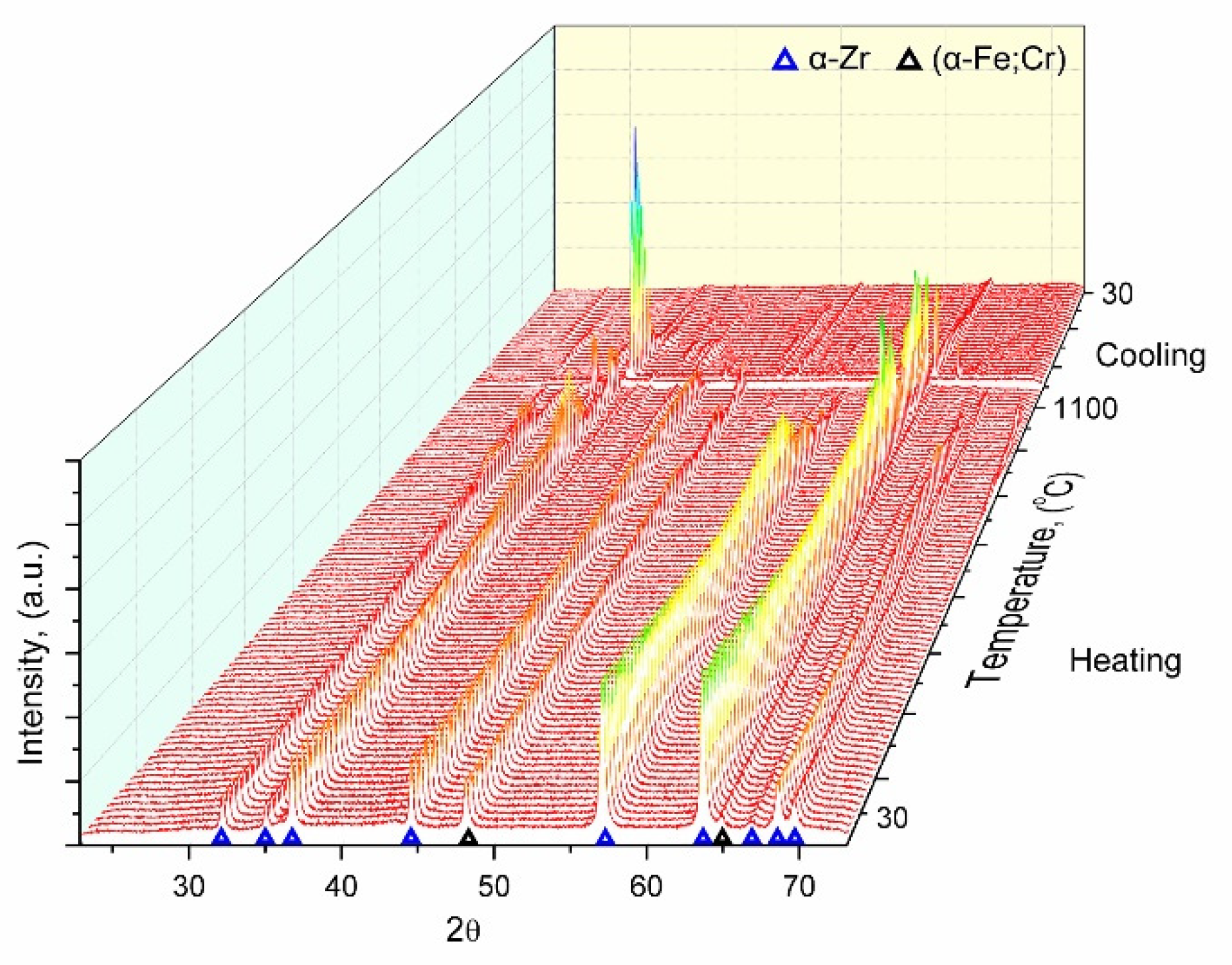
The in-situ study of the evolution of the phase composition was carried out for the Fe-Cr-Al-Zr SA formed using mode (1). X-ray patterns obtained upon the sample heating are presented in
Figure 4 as waterfall charts.
As followed from
Figure 4, no changes in the phase composition were observed up to 1173 K, i.e. the SA structure was thermally stable. The reflections of the main α-Zr and α-Fe phases were shifted towards lower angles due to an increase in the lattice parameters as a result of thermal expansion. In the range of 1173–1223 K, new phases were found, which could be attributed to the FeZr
2 compound with a cubic or tetragonal structure. Signs of the α-Zr→β-Zr phase transition were detected at ≈1253 K, which was about 100 K greater than the known reference data [
11]. The intensity of the new phases enhanced with rising temperature up to ≈1523°K, which indicated an increase in their contents. At a temperature of ≈1543 K, almost all reflections were negligible in the X-ray diffraction patterns, reflecting the SA amorphization. This phenomenon could be associated with melting of the surface layer. Concerning the thermal stability of the obtained amorphous transition layer, it has been expected that this structure is preserved upon heating by minimum of hundreds of degrees, since a similar pattern was observed for a Ti-Ta-Ni SA synthesized by the authors of [
12].
4. Conclusions
Two SA types had been formed by LEHCEB processing. The first type, after weak melting, was characterized by the chemical composition corresponding to that of the pre-deposited film. In the second SA, the film atoms had been mixed with the substrate ones, displaced to the surface in the liquid phase during intense melting.
As a result of LEHCEB processing of the initial (Fe-Cr-Al)/Zr film–substrate system, the two-layer SA of 1.3 μm in thick was synthesized. It included the surface Fe69Cr20Al11 at.% relatively large-grained (~1 µm) layer and another amorphous one below, consisted of two Fe64–54Zr8–22Cr21–17Al8–7 and Fe40–16Zr42–78Cr12–4Al6–2 (at.%) sublayers.
In the zirconium concentration range of 22–42 at.%, an amorphous layer had not been formed, but the finely dispersed phases with the nanocrystalline structure were observed.
In terms of preventing intergranular diffusion of oxygen from the environment into the substrate and zirconium in the opposite direction, the Fe-Cr-Al-Zr SA synthesized using mode (1) was an ‘ideal’ coating, because in the first crystalline layer, the number of grain boundaries was negligible compared to that of the pre-deposited film, while grain boundaries were absent in the second Fe-Cr-Al-Zr amorphous sublayer. Moreover, the structure of SA synthesized was thermally stable.
Author Contributions
Conceptualization, A.B.M.; methodology, A.B.M. and E.V.Y.; software, A.V.S.; validation, A.B.M., A.V.S. and M.S.S.; formal analysis, E.V.Y. and A.V.S.; investigation, E.V.Y.; writing—original draft preparation, A.B.M.; writing—review and editing, E.V.Y., M.S.S.; visualization, E.V.Y and A.V.S.; supervision, A.B.M. All authors have read and agreed to the published version of the manuscript.
Funding
The experimental part of the work was carried out with the financial support of Russian Federation represented by Ministry of Science and Higher Education (project No. 075-15-2021-1348). Whereas calculations were made with the support by the Ministry of Science and Higher Education of the Russian Federation (project No FWRF-2021-0001).
Institutional Review Board Statement
Not applicable.
Informed Consent Statement
Not applicable.
Data Availability Statement
Data used are available on request from the corresponding author.
Conflicts of Interest
The authors declare no conflict of interest.
References
- Zhang, C.; Guan, J.; Tian, S.; Sun, C.; Ma, C.; Kan, E.; Guan, Q.; Lu, J. The Surface Alloying of Aluminum with Sn and Pb for Enhancement Mechanism under High Current Pulsed Electron Beam. Surf. Coatings Technol. 2022, 444, 128640. [CrossRef]
- Markov, A.; Yakovlev, E.; Shepel’, D.; Bestetti, M. Synthesis of a Cr-Cu Surface Alloy Using a Low-Energy High-Current Electron Beam. Results Phys. 2019, 12, 1915–1924. [CrossRef]
- Rotshtein, V.; Ivanov, Y.; Markov, A. Surface Treatment of Materials with Low-Energy, High-Current Electron Beams. Mater. Surf. Process. by Dir. Energy Tech. 2006, 205–240. [CrossRef]
- Ivanov, Y.F.; Prokopenko, N.A.; Petrikova, E.A.; Shugurov, V. V.; Teresov, A.D. Multilayer Amorphous-Crystalline High-Entropy Metal Films. Izv. Ferr. Metall. 2023, 66, 191–196. [CrossRef]
- Brachet, J.C.; Rouesne, E.; Ribis, J.; Guilbert, T.; Urvoy, S.; Nony, G.; Toffolon-Masclet, C.; Le Saux, M.; Chaabane, N.; Palancher, H.; et al. High Temperature Steam Oxidation of Chromium-Coated Zirconium-Based Alloys: Kinetics and Process. Corros. Sci. 2020, 167, 108537. [CrossRef]
- Markov, A.; Solovyov, A.; Yakovlev, E.; Slobodyan, M. Prediction of the Composition of Surface Alloys Formed via Pulsed Melting of Preliminary Deposited Coatings. Mater. Chem. Phys. 2022, 292, 126821. [CrossRef]
- Li, C.L.; Murray, J.W.; Voisey, K.T.; Clare, A.T.; McCartney, D.G. Amorphous Layer Formation in Al86.0Co7.6Ce6.4 Glass-Forming Alloy by Large-Area Electron Beam Irradiation. Appl. Surf. Sci. 2013, 280, 431–438. [CrossRef]
- Guan, Q.F.; Zou, H.; Zou, G.T.; Wu, A.M.; Hao, S.Z.; Zou, J.X.; Qin, Y.; Dong, C.; Zhang, Q.Y. Surface Nanostructure and Amorphous State of a Low Carbon Steel Induced by High-Current Pulsed Electron Beam. Surf. Coatings Technol. 2005, 196, 145–149. [CrossRef]
- Mojaver, R.; Mojtahedi, F.; Shahverdi, H.R.; Torkamany, M.J. Study on Feasibility of Producing an Amorphous Surface Layer of Fe49Cr18Mo7B16C4Nb3 by Pulsed Nd:YAG Laser Surface Melting. Appl. Surf. Sci. 2013, 264, 176–183. [CrossRef]
- Audebert, F.; Colaço, R.; Vilar, R.; Sirkin, H. Production of Glassy Metallic Layers by Laser Surface Treatment. Scr. Mater. 2003, 48, 281–286. [CrossRef]
- Stein, F.; Sauthoff, G.; Palm, M. Experimental Determination of Intermetallic Phases, Phase Equilibria, and Invariant Reaction Temperatures in the Fe-Zr System. J. Phase Equilibria 2002, 23, 480–494. [CrossRef]
- Semin, V.O.; Gudimova, E.Y.; Neiman, A.A.; D’yachenko, F.A.; Meisner, L.L. Local Structure and Medium-Range Order in a Glassy Ti-Ta-Based Surface Alloy after Low-Temperature Annealing Studied by Electron Nano-Beam Diffraction. Mater. Charact. 2021, 174, 110967. [CrossRef]
|
Disclaimer/Publisher’s Note: The statements, opinions and data contained in all publications are solely those of the individual author(s) and contributor(s) and not of MDPI and/or the editor(s). MDPI and/or the editor(s) disclaim responsibility for any injury to people or property resulting from any ideas, methods, instructions or products referred to in the content. |
© 2023 by the authors. Licensee MDPI, Basel, Switzerland. This article is an open access article distributed under the terms and conditions of the Creative Commons Attribution (CC BY) license (http://creativecommons.org/licenses/by/4.0/).


