Submitted:
18 July 2023
Posted:
19 July 2023
You are already at the latest version
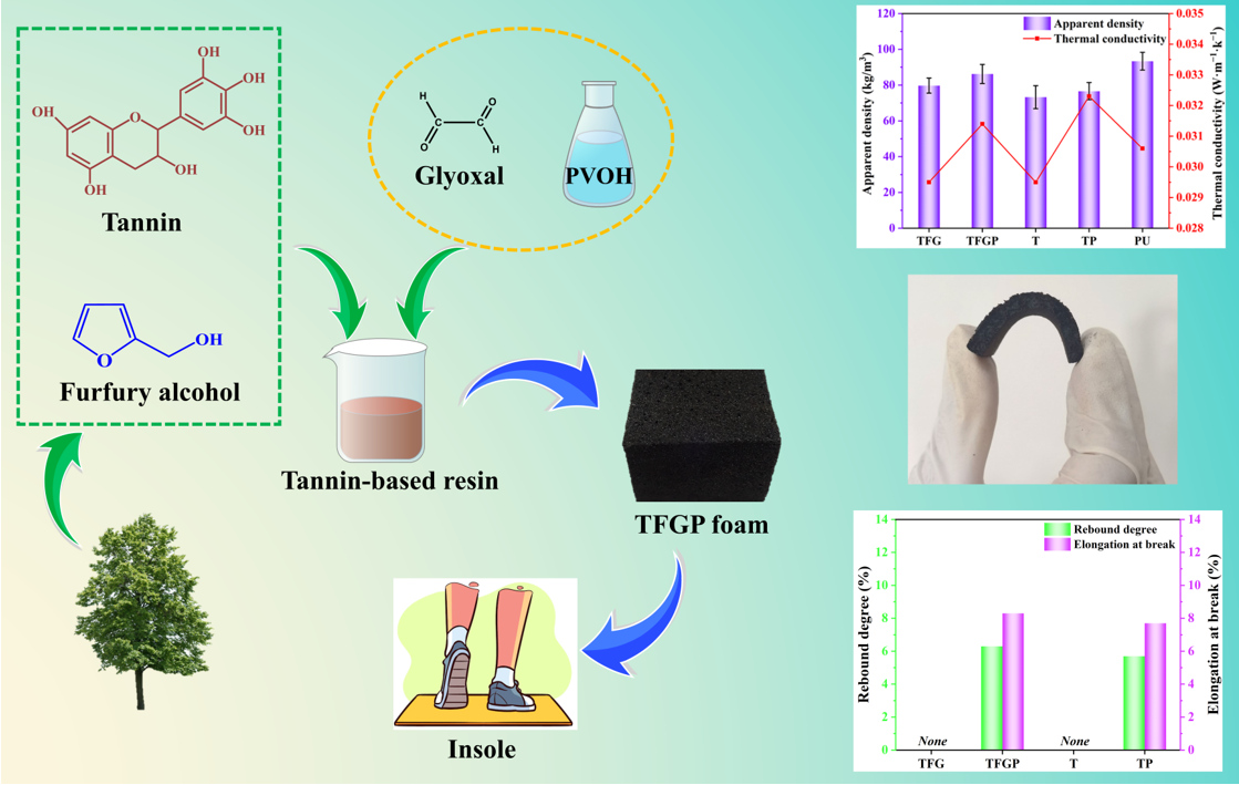
Abstract
Keywords:
1. Introduction
2. Materials and Methods
2.1. Materials
2.2. Preparation of flexible tannin-furanic resin-based foams
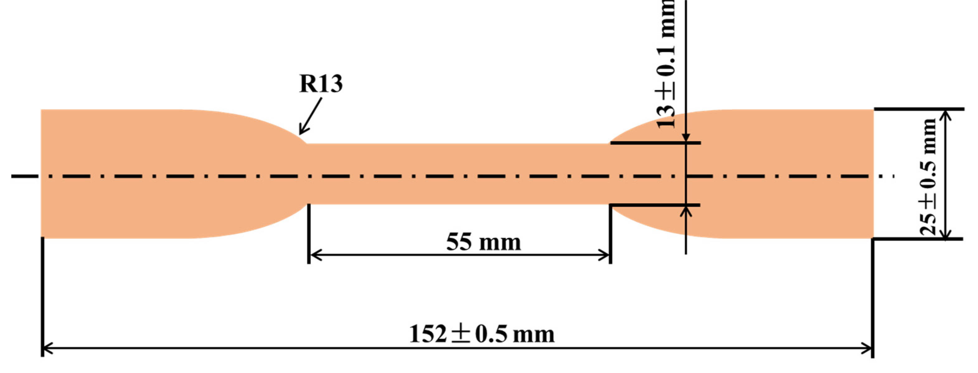
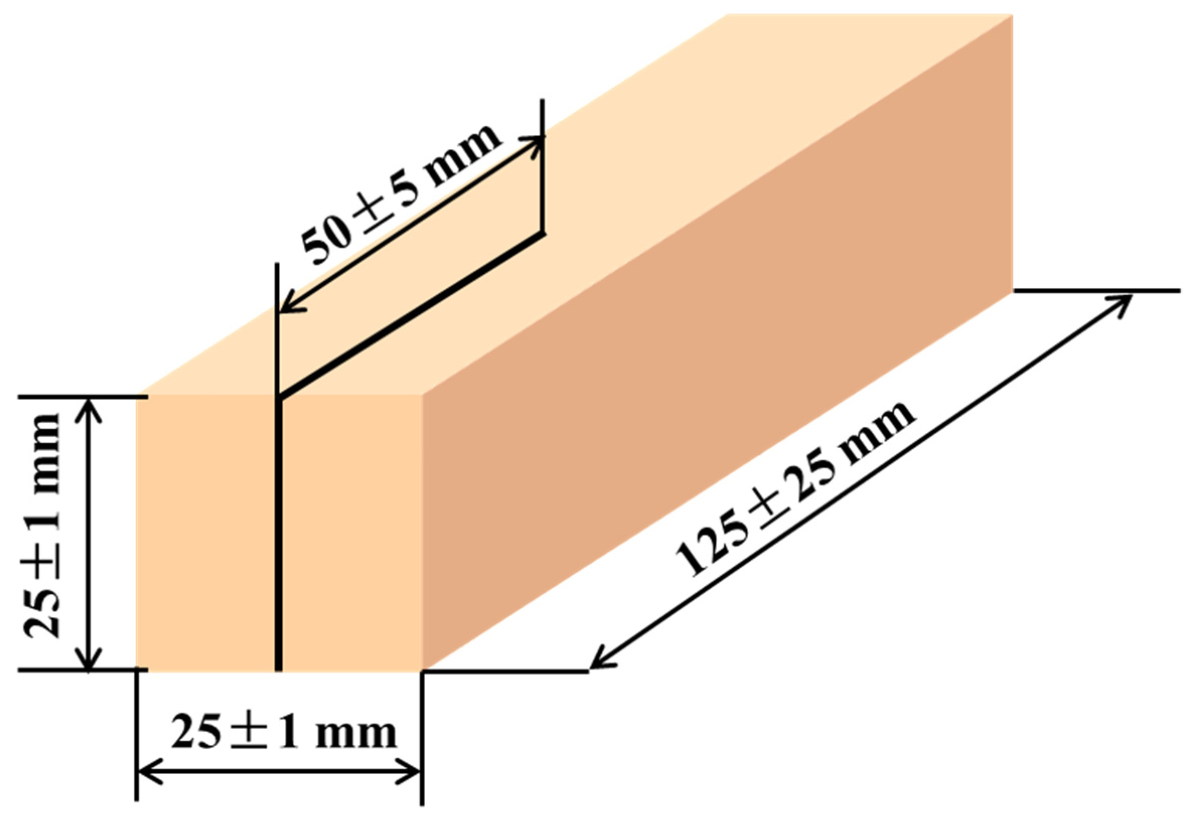
2.3. Characterizations
3. Results and discussion
4. Conclusions
Author Contributions
Acknowledgments
Conflicts of Interest
References
- www.worldfootwear.com/news/european-footwear-production-drops-in-the-last-4-decades/8723.html.
- Bernardini, J.; Anguillesi, I.; Coltelli, M.B.; Cinelli, P.; Lazzeri, A. Optimizing the lignin based synthesis of flexible polyurethane foams employing reactive liquefying agents. Polym. Int. 2015, 64, 1235–1244. [Google Scholar] [CrossRef]
- Kohan, L.; Martins, C.R.; Duarte, L.O.; Pinheiro, L.; Baruque-Ramos, J. Panorama of natural fibers applied in Brazilian footwear: materials and market. SN Applied Sciences 2019, 1, 895. [Google Scholar] [CrossRef]
- Morita, J.; Ando, Y.; Komatsu, S.; Matsumura, K.; Okazaki, T.; Asano, Y.; Nakatani, M.; Tanaka, H. Mechanical Properties and Reliability of Parametrically Designed Architected Materials Using Urethane Elastomers. Polymers 2021, 13, 842. [Google Scholar] [CrossRef] [PubMed]
- Zhang, Y.; Wang, Z.; Yu, P.; Yang, X.; Sun, Z.; Zhang, Y.; Wu, Y.; Jiang, C. Ultrasensitive and wide-range reduced graphene oxide/natural rubber foam sensors for multifunctional self-powered wireless wearable applications. Compos. Sci. Technol. 2022, 226, 109560. [Google Scholar] [CrossRef]
- Anggoro, P.W.; Bawono, B.; Jamari, J.; Tauviqirrahman, M.; Bayuseno, A.P. Advanced design and manufacturing of custom orthotics insoles based on hybrid Taguchi-response surface method. Heliyon. 2021, 7, e06481. [Google Scholar] [CrossRef]
- Li, N.; Yick, K.; Yu, A. Novel weft-knitted spacer structure with silicone tube and foam inlays for cushioning insoles. J. Ind. Text. 2022. [Google Scholar] [CrossRef]
- Aristri, M.A.; Lubis, M.A.R.; Yadav, S.M.; Antov, P.; Papadopoulos, A.N.; Pizzi, A.; Iswanto, A.H. Recent developments in lignin-and tannin-based non-isocyanate polyurethane resins for wood adhesives—A review. Appl. Sci. 2021, 11, 4242. [Google Scholar] [CrossRef]
- Chen, M.S.; Luo, J.; Shi, R.Q.; Zhang, J.Z.; Gao, Q.; Li, J. Improved adhesion performance of soy protein-based adhesives with a larch tannin-based resin. Polymers 2017, 9, 408. [Google Scholar] [CrossRef] [PubMed]
- Ghahri, S.; Chen, X.; Pizzi, A.; Hajihassani, R.; Papadopoulos, A.N. Natural tannins as new cross-linking materials for soy-based adhesives. Polymers 2021, 13, 595. [Google Scholar] [CrossRef] [PubMed]
- Esmaeili, N.; Salimi, A.; Zohuriaan-Mehr, M.J.; Vafayan, M.; Meyer, W. Bio-based thermosetting epoxy foam: Tannic acid valorization toward dye-decontaminating and thermo-protecting applications. J. Hazard. Mater. 2018, 357, 30–39. [Google Scholar] [CrossRef] [PubMed]
- Li, J.; Liao, J.; Essawy, H.; Zhang, J.; Zhou, X. Preparation and characterization of novel cellular/nonporous foam structures derived from tannin furanic resin. Ind. Crops Prod. 2021, 162, 113264. [Google Scholar] [CrossRef]
- Khundamri, N.; Aouf, C.; Fulcrand, H.; Dubreucq, E.; Tanrattanakul, V. Bio-based flexible epoxy foam synthesized from epoxidized soybean oil and epoxidized mangosteen tannin. Ind. Crops Prod. 2019, 128, 556–565. [Google Scholar] [CrossRef]
- Zhang, J.; Liu, B.; Zhou, Y.; Essawy, H.; Liang, J.; Zhou, X.; Du, G. Preparation and characterization of a bio-based rigid plastic based on gelatinized starch cross-linked with furfural and formaldehyde. Ind. Crops Prod. 2022, 186, 115246. [Google Scholar] [CrossRef]
- Lagel, M.C.; Pizzi, A.; Basso, M.C.; Abdalla, S. Development and characterization of abrasive grinding wheels with a tanninfuranic resins matrix. Ind. Crops Prod. 2015, 65, 343–348. [Google Scholar] [CrossRef]
- Liu, B.; Zhou, Y.; Essawy, H.; Feng, S.; Li, X.; Liao, J.; Zhou, X.; Zhang, J.; Xie, S. Formaldehyde Free Renewable Thermosetting Foam Based on Biomass Tannin with a Lignin Additive. JOURNAL OF RENEWABLE MATERIALS 2022, 10, 3009–3024. [Google Scholar] [CrossRef]
- Chen, X.; Guigo, N.; Pizzi, A.; Sbirrazzuoli, N.; Li, B.; Fredon, E.; Gerardin, C. Ambient Temperature Self-Blowing Tannin-Humins Biofoams. Polymers 2020, 12, 2732. [Google Scholar] [CrossRef] [PubMed]
- Li, X.; Nicollin, A.; Pizzi, A.; Zhou, X.; Sauget, A.; Delmotte, L. Natural tannin–furanic thermosetting moulding plastics. RSC Adv. 2013, 3, 17732–17740. [Google Scholar] [CrossRef]
- Zhang, J.; Xi, X.; Liang, J.; Pizzi, A.; Du, G.; Deng, S. Tannin-based adhesive cross-linked by furfuryl alcohol-glyoxal and epoxy resins. Int. J. Adhes. Adhes. 2019, 94, 47–52. [Google Scholar] [CrossRef]
- Li, Y.; Deng, J.; Zhang, J. Porous poly(vinyl formal) foam prepared using poly(vinyl alcohol) of low degree of polymerization. Polym. Int. 2018, 67, 1438–1444. [Google Scholar] [CrossRef]
- Xu, Y.; Liu, B.; Zheng, L.; Zhou, Y.; Essawy, H.; Chen, X.; Zhou, X.; Zhang, J. Facile Fabrication of High-Performance Composite Films Comprising Polyvinyl Alcohol as Matrix and Phenolic Tree Extracts. Polymers 2023, 15, 1424. [Google Scholar] [CrossRef]
- Wang, M.; Bai, J.; Shao, K.; Tang, W.; Zhao, X.; Lin, D.; Huang, S.; Chen, C.; Ding, Z.; Ye, J. Poly(vinyl alcohol) Hydrogels: The Old and New Functional Materials. Int. J. Polym. Sci. 2021. [Google Scholar] [CrossRef]
- Zhou, X.; Li, B.; Xu, Y.; Essawy, H.; Wu, Z.; Du, G. Tannin-furanic resin foam reinforced with cellulose nanofibers (CNF). Ind. Crops Prod. 2019, 134, 107–112. [Google Scholar] [CrossRef]
- Zhang, H.; Fang, W.; Li, Y.; Tao, W. Experimental study of the thermal conductivity of polyurethane foams. Appl. Therm. Eng. 2017, 115, 528–538. [Google Scholar] [CrossRef]
- Baltich, J.; Maurer, C.; Nigg, B.M. Increased vertical impact forces and altered running mechanics with softer midsole shoes. PLOS ONE 2015, 10, e0125196. [Google Scholar] [CrossRef] [PubMed]
- Anggoro, P.W.; Bawono, B.; Jamari, J.; Tauviqirrahman, M.; Bayuseno, A.P. Advanced design and manufacturing of custom orthotics insoles based on hybrid Taguchi-response surface method. Heliyon 2021, 7, e06481. [Google Scholar] [CrossRef] [PubMed]
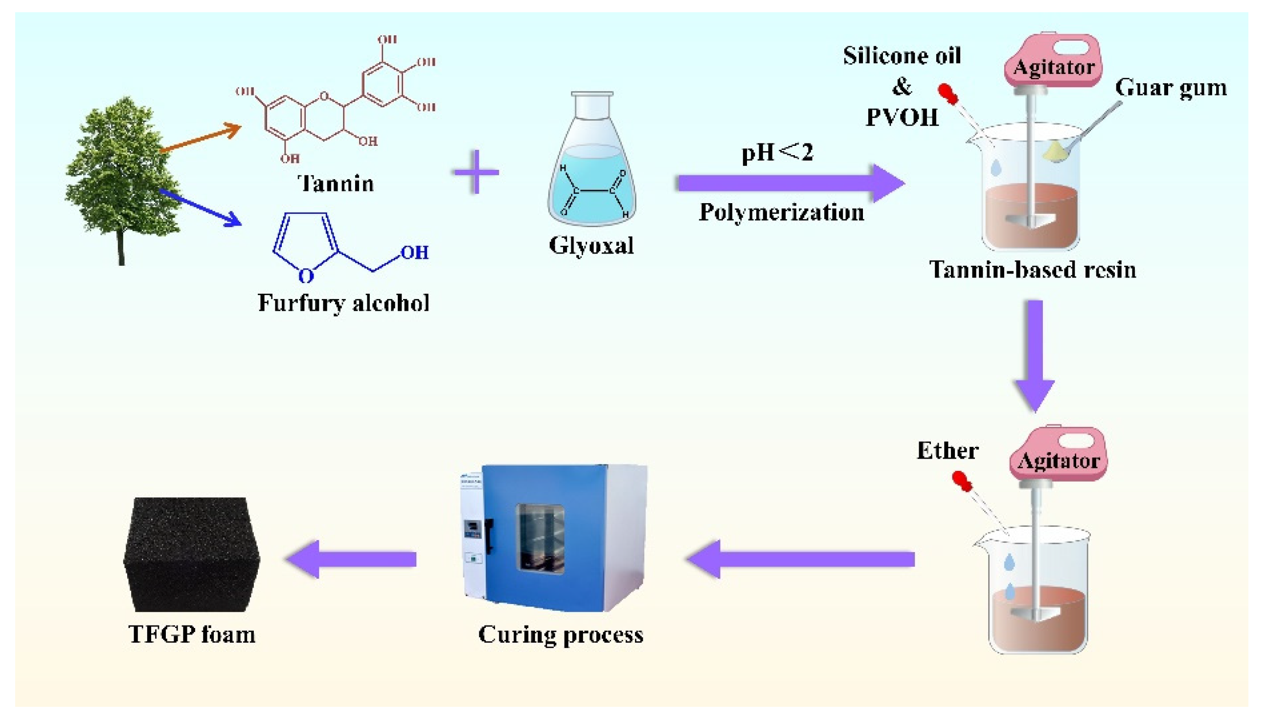
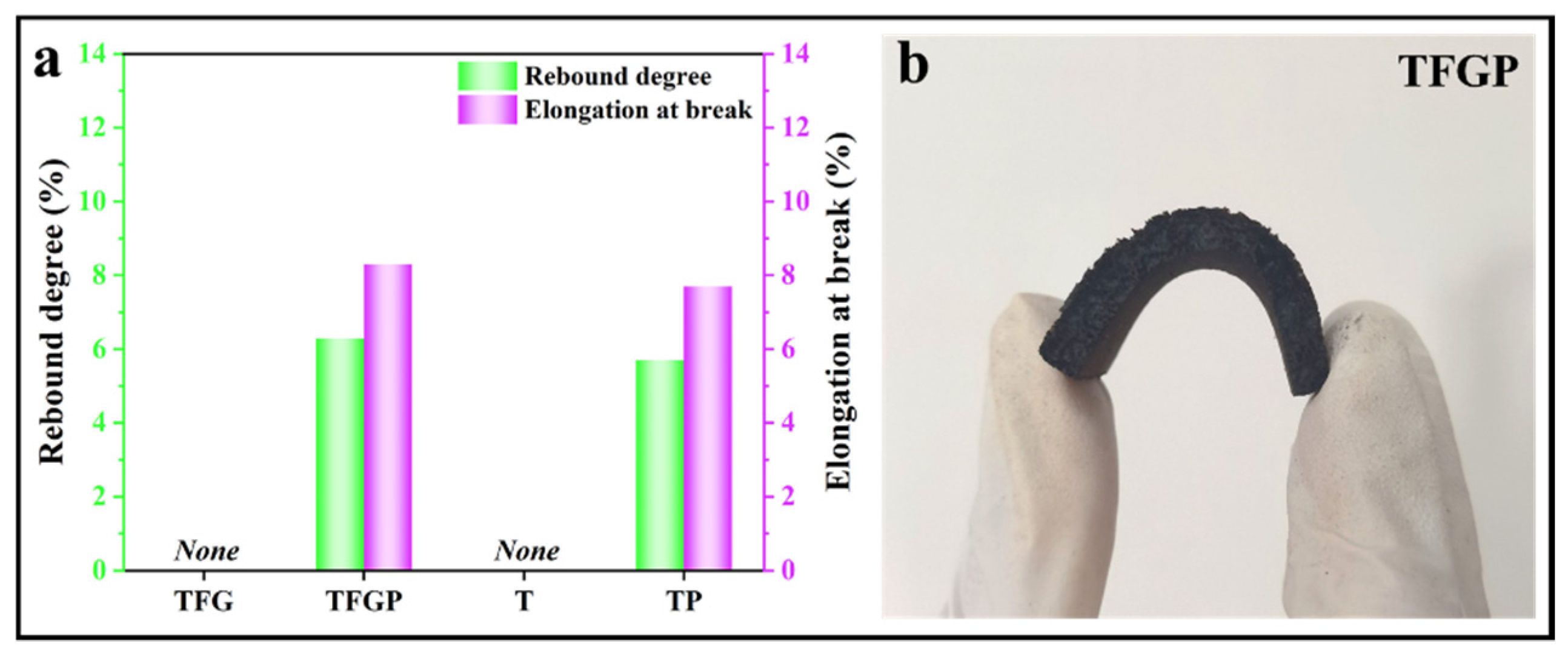
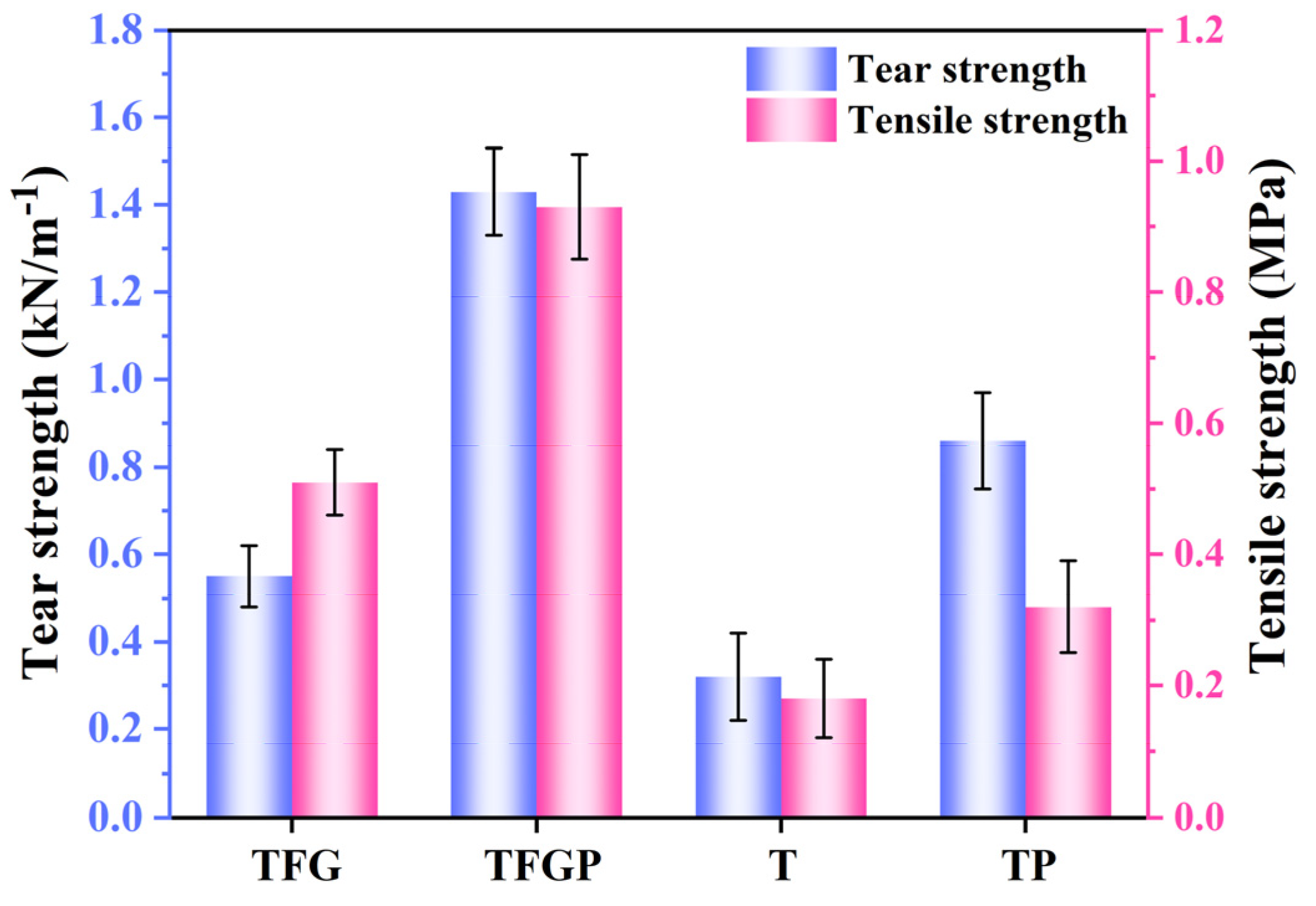
| Type | Tannin/g | Distilled Water/g | Furfuryl Alcohol/g | Glyoxal/g | Ether/g | Tween 80/g | Guar Gum/g | pTSA/g | PVOH/g |
|---|---|---|---|---|---|---|---|---|---|
| T | 20 | 10 | 0 | 0 | 0 | 4 | 2 | 0 | 0 |
| TP | 20 | 10 | 0 | 0 | 0 | 4 | 2 | 0 | 15 |
| TFG | 30 | 0 | 20 | 10 | 2 | 4 | 2 | 15 | 0 |
| TFGP | 30 | 0 | 20 | 10 | 2 | 4 | 2 | 15 | 15 |
Disclaimer/Publisher’s Note: The statements, opinions and data contained in all publications are solely those of the individual author(s) and contributor(s) and not of MDPI and/or the editor(s). MDPI and/or the editor(s) disclaim responsibility for any injury to people or property resulting from any ideas, methods, instructions or products referred to in the content. |
© 2023 by the authors. Licensee MDPI, Basel, Switzerland. This article is an open access article distributed under the terms and conditions of the Creative Commons Attribution (CC BY) license (https://creativecommons.org/licenses/by/4.0/).


