Introduction
Strabismic disease is a misalignment of the eyeballs and includes a heterogeneous group of eye movement disorders characterised by permanent or temporary deviation (1–4). Strabismus occurs in 4-6% of the population worldwide, with little geographic variation, in both children and adults, with equal frequency in both men and women (3, 5). Findings have shown that the strabismic disease occurs in 65% by the age of 3 and is one of the most common visual disorders in preschool children (6, 7). Proper measurement of the type and magnitude of eye deviation is essential for correct diagnosis, observation, and treatment of strabismus (8, 9).
Undetected and untreated strabismic disease leads to varying degrees of stereoscopic vision limitation and the development of amblyopia in the eye where strabismus is consistently present. It can also lead to postural abnormalities and torticollis, accompanied by spinal pain, mainly in the cervical region, which can lead to further long-term orthopaedic complications. The condition reduces the quality of life and impairs daily functioning (10). Adequate treatment by enabling stereoscopic vision, through prompt diagnosis and appropriate surgery, can prevent potentially fatal accidents such as falls from ladders or car accidents resulting from poor spatial judgment. In addition, by properly aligning the eyes, which is an important point in the aesthetics of the patient's appearance and has a significant impact on his or her well-being and self-esteem, among other things, depression and, in extreme cases, the resulting potential suicide attempts can be avoided.
Evaluation by conventional methods
The primary manual methods for diagnosing strabismic disease are the Hirschberg test, the Krimsky test, the cover-uncover test, and the Prismatic cover test (PCT). The Hirschberg test evaluates the parallel alignment of the eyeballs based on the location of reflections on the surface of the illuminated cornea. The Krimsky test is a modification of the Hirschberg test, adding prisms in the visual axis to quantitatively measure the amount of deviation for both near and far (11). Both tests are considered the gold standard for testing eye alignment in uncooperative individuals, i.e. infants or people with mental disabilities (12, 13). The results of both Hirschberg and Krimsky tests performed depend on the subjective judgment of the examiner and are much less accurate than the other available strabismus angle tests, even when performed by experienced strabologists (14, 15). Currently, the gold standard for assessing eye deviation is the cover-uncover test and the PCT in which prism bars are additionally used. These tests should be performed for both near and far. These tests are time-consuming, and differences in measurements by other researchers can be as high as 10PD (16, 17).
Prism bars are commonly used in ophthalmology and orthoptic offices to determine the strength of the corrective prism values by performing the PCT. When evaluating eye deviation to the distance, the patient fixes his or her gaze on an object at a distance of 6 meters, which requires a large space in the office (18). This test can be unreliable since it requires the examiner to simultaneously cover the patient's eye, hold the prism bar, visually observe eye movements, and correct the patient's posture. Detecting the moment when eye movement stops is another obstacle in PCT examination, which is particularly difficult when there are numerous reflections in refractive glasses and prism bars. Most often, this is due to the inadequate positioning of the exam chair in relation to the room lighting, over which the examiner has little influence. A manual occluder does not completely block the light that enters the eye, and partial perimeter of the field of view (FoV) may result in partial recovery of the binocular fusion. Strabismus examination requires the patient's cooperation, remaining in a stable and fixed position for an extended period, and in the case of complex vertical and horizontal or oblique strabismus or uncooperative patients, requires the assistance of additional people to stabilise the head or operate additional prism bars. The accuracy of the test drops significantly for large deviation values due to the variable resolution of the prism bars. The interval between prism power values is 1PD in the 1-10PD range, then 2PD in the 10-20PD range, and as much as 5PD at higher values. In the PCT test, the prism bars should be aligned perpendicular to the optical axis of the eye in all planes, which again requires the experience of the examiner and is not verified in any way. The bars have no indicators of correct alignment, and greater the deviation, the greater the measurement error. The skill and experience of the examiner play an important role, as well as factors such as the psychophysical state of the examiner and patient, the time of day or coexisting diseases, such as developmental disabilities (18). The difficulty of the performed tests, and the role of the examiner's experience is evidenced by the development of a virtual reality strabismus angle assessment training application, the use of which significantly improves the examiner's accuracy and efficiency (19).
An optical-mechanical synoptophore is also used to measure strabismic angles (20). This device consists of two rotating optical tubes that are attached to the patient's eyes and display two complementary static images. As a result of the appropriate adjustment of the tubes by the examiner or the patient himself, it is possible to combine the images into one image. At the same time, as the rotation of the tubes proceeds, the images are alternately extinguished, forcing the patient's eyes to adjust. The optometrist evaluates the strabismic angle at far and near fixation distance, based on the visual assessment of the adjustment movements and the actual angles of rotation of the tubes (read from the scale or digital encoders). The synoptophores are difficult to use and require a great deal of experience on the part of the examiner, and the results depend on the psychophysical condition and subjective vision of the patient. In addition, numerous reports have been made by doctors and optometrists that there are problems with the evaluation of the strabismic angles in distant vision, especially the overestimation of the angles in convergent strabismus, and the underestimation of the angles in divergent strabismus.
Advanced autorefractometers have implemented the strabismic angle measurement by measuring corneal reflectance on the pupil area (e.g., PlusOptix). In a simplified form, this measurement is performed manually by optometrists using a point light source held at a distance from the patient's head, called the Hirshberg test (21). The location of the glare allows only a preliminary diagnosis of the type of strabismus and the value of the deviation.
Scientific articles
Researchers around the world are working to develop new devices for more accurate and prompt diagnosis of strabismic disease (7, 22–29). Numerous scientific articles report methods for estimating strabismus angles based on analysis of reflections on the pupil area, reflections from the cornea and deeper layers, and those based on the shape of the pupil in camera images.
Yehezkel O et al. developed a test station to examine the type and magnitude of ocular deviation, based on an off-the-shelf system for corneal reflection analysis (25). The tests were performed only for nearsightedness.
Huang X et al. proposed a method for quick diagnosis of strabismus based on analysis of facial peculiarities and detection of the position of the corneal reflex relative to the iris contour. The method is mainly based on the analysis and processing of camera images and, according to the authors, can be used as a screening method outside of doctors' offices, but is not used to determine strabismus angles (30).
Yang Z et al. presented a device that automates a standard cover-uncover test, recording eye movement on video while observing the fixation point on the screen (31, 32). The article does not adequately explain how to determine strabismus angles, which the authors determine by converting changes in pupil position in pixels directly into prism diopters, using a dpMM constant chosen in an unknown way. In our opinion, this approach will result in large errors and cannot be used for accurate strabismus diagnosis, given the fact that eye movements are observed at low resolution with a single camera.
Mao K et al. developed artificial intelligence methods based on neural networks for suggesting the extent of surgery. The system is based solely on pairs of corneal reflection images of patients with exotropia, and no other data, such as postoperative strabismus measurements in the same patients or standard surgical guidelines, were used to train the network (33).
Chen ZH et al. developed a system exclusively for detecting the presence and tendency of strabismus, resembling the standard Hess test in principle. Infrared illumination was used to analyse pupil movement. The same authors, in another article, proposed the use of convolutional neural networks to detect the presence of strabismus (34).
Similarly, Weber KP et al. developed goggles with integrated infrared cameras for observing pupil movement and LCD screens for alternating eye covering. This device was used in a prototype simulating the standard Hess test, but, as the authors point out, the device is not directly used to determine strabismus angles (22).
Mestre C et al. designed and developed an automated system for measuring heterophoria, which is based on the EyeLink 1000 Plus commercial eye-tracking system and a regular and constant fixation pattern (35). The presented technique was compared with the traditional cover-uncover test and the modified Thorington test (36). Better repeatability and accuracy were obtained, and according to the authors, the measurements were objective. However, the mathematical principles of eye tracker calibration are not known, particularly how and how accurately the eye axis position is determined. Although patients are asked to wear habitual lens correction for the test, the system measures heterophoria only at a close distance of 40 cm, which requires accommodation and induces convergence.
Miao et al. published the results of a strabismus angle study using a modern device based on virtual reality technology, in which the strabismus angle is estimated based on eye movement tracking (37). The developers of the above device noted that VR users perceive space and motion poorly due to the mismatch between the patients' pupillary distance (PD) and the device's fixed PD of 63.5 mm, as well as the compression of all distances in the virtual environment.
However, in our opinion, these methods are unreliable as they do not take into account the actual path of light from the observed object to the macula on the retina, often far from the ideal anatomy of the eye, even despite the estimation of the Kappa angle. Both methods can only provide a preliminary estimate of the diagnosis indicating the presence and type of strabismus.
Yehezkel O et al. developed an automatic strabismus measurement device with an eye tracking system, video goggles for performing the Hess test, and binaural optical coherence tomography (8). Among the limitations of the system, it should be noted that the device is designed to measure the full range of deviation in 1PD increments. Researchers of the aforementioned solution point out that poor head positioning in the device adopted by the participant during the automated test may have contributed to the failure to detect ocular deviation.
Chopra R et al. also used common optical coherence tomography to study strabismus angles (23). The results of the study suggest that binocular anterior OCT can provide clinicians with an accurate measurement of strabismus. The prototype provides quantitative data and will facilitate the diagnosis and monitoring of ocular misalignment. However, the device may not be reliable for diagnosing small deviations (< 2PD), especially vertical deviations.
Patent applications
Devices and methods for observing and measuring eye movements are the subject of numerous patent applications, e.g., a digital synoptophore for type and degree diagnosis, consisting of cameras, LCD screens and eye movement detection (38). Such a solution does not allow automatic mapping of the intensity of adjustable eye movement to the angle of the optical modules for optotype projection.
The spotlight reflex observations described in patents are commonly used to assess strabismus (39–43). Moreover, one patent considers corneal reflectors in combination with a theoretical model of the eyeball to assess the position of the eye axis in space and determine the angle of strabismus (44).
Other patents present solutions for measuring the strabismus angles, which are based on displaying stereoscopic images e.g., in VR goggles and recording eye movements with a camera system (45, 46). The computer controls the position of the optotypes, evaluates the range of movement of both pupils and determines the new optotype shift until the pupil movements stop. However, both solutions do not disclose methods of FoV calibration with respect to the individual patient characteristics, in particular PD and refractive errors, which together can influence the convergence and the final measurements.
Solutions can be found that demonstrate goggles with integrated IR cameras for pupil tracking and LCD screens for alternating eye covering. They enable an automated Hess test, which is the evaluation of eye movement only (47, 48).
A different solution presents a device based on VR goggles that corrects the view of the actual surrounding (49). Two cameras are mounted to the front of the goggles, and an integrated computer transforms the images so that the vision of the strabismic patient is not disturbed. The image transformations are based on separate medical examinations and recorded eye movements. However, the solution does not disclose details of the FoV calibration and method of images transformation.
A different solution presents a device for diagnosing the presence and direction of the strabismus, performing automatic eyes covering using a mechanical occluder, and recording eye movements in images with cameras (50). Graphic patterns are displayed on two screens placed in front of the patient. Additional prisms are mounted on the head support, the size of which is selected after a preliminary study in a qualitative experiment. The solution performs the test at near and distance fixation but does not reveal how the strabismus angle is determined or the degree of automation of these measurements.
To the best of our knowledge, the state of the art does not know of any means or devices functionally and technically similar to the solution presented in this study.
Results
Characterization of the collected patient features was carried out using descriptive statistics such as mean, standard deviation (SD), minimum and maximum values, as well as counts and percentages. Compliance with the normal distribution of continuous variables was checked using the Shapiro-Wilk W test. Comparisons of test values, separately at near and far fixation, between devices and comparisons of test teasing between them were made using the Mann-Whitney U test. A Receiver Operating Characteristic (ROC) curve was calculated based on the near and far examination results from each device to compare the diagnostic capabilities of the devices. Parameters such as sensitivity, specificity, and area under the ROC curve – AUC (area under the curve) – were calculated. In addition, the concordance of results from the two devices was compared using Cochran's Q test. Results were considered statistically significant at p<0.05.
Basic patient demographics are shown in
Table 1. The study group included 30 patients with manifest strabismus, while the second group included 30 healthy subjects without manifest strabismus. The measurements taken were compared to the traditionally used PCT, and a 55% concordance of positive results and a 45% concordance of negative results for distance were obtained. At near fixation, the percentage of positive results was concordant at 38.3% and negative at 61.7%. The device correctly detected strabismus in all subjects, as well as detecting small angles of hidden strabismus <2PD that were not detected by PCT (in 11 patients). The described difference is related to the difficulty of capturing with the "naked" eye the small adjusting movements of the eyes during the PCT test, which are easily detected by the Strabiscan device. Due to the described difficulties in the PCT test, we suggest that the values read from the Strabiscan device might be characterised by higher measurement accuracy. In the control group, using the Strabiscan device, small-angle latent strabismus ≤3PD was diagnosed in 25/30 patients (83%) and >3PD in 4/30 patients (13%). In contrast, using the PCT test, latent strabismus ≤3PD was diagnosed in only 4/30 13% of patients, and latent strabismus with an angle of >3PD in 4/30 (13%) patients.
Strabismus at near fixation using the PCT test was diagnosed among 23 patients from the healthy group (76%) and in 28 patients with the strabismic disease (93%). Using Strabiscan, strabismus to nearsightedness was observed among 28 patients from the healthy group (93%) and 30 patients with the strabismic disease (100%).
Table 2 shows detailed features on the diagnosis and treatment of strabismic disease in the study group.
The comparative results of the PCT method and the Strabiscan device are shown in
Table 3. No statistically significant differences were noted in the measurements of strabismus angles performed by the different methods. Comparing the inconvenience of performing the tests for the patient, less inconvenience was noted in the test performed with the Strabiscan device than with the PCT method, but the difference was not statistically significant.
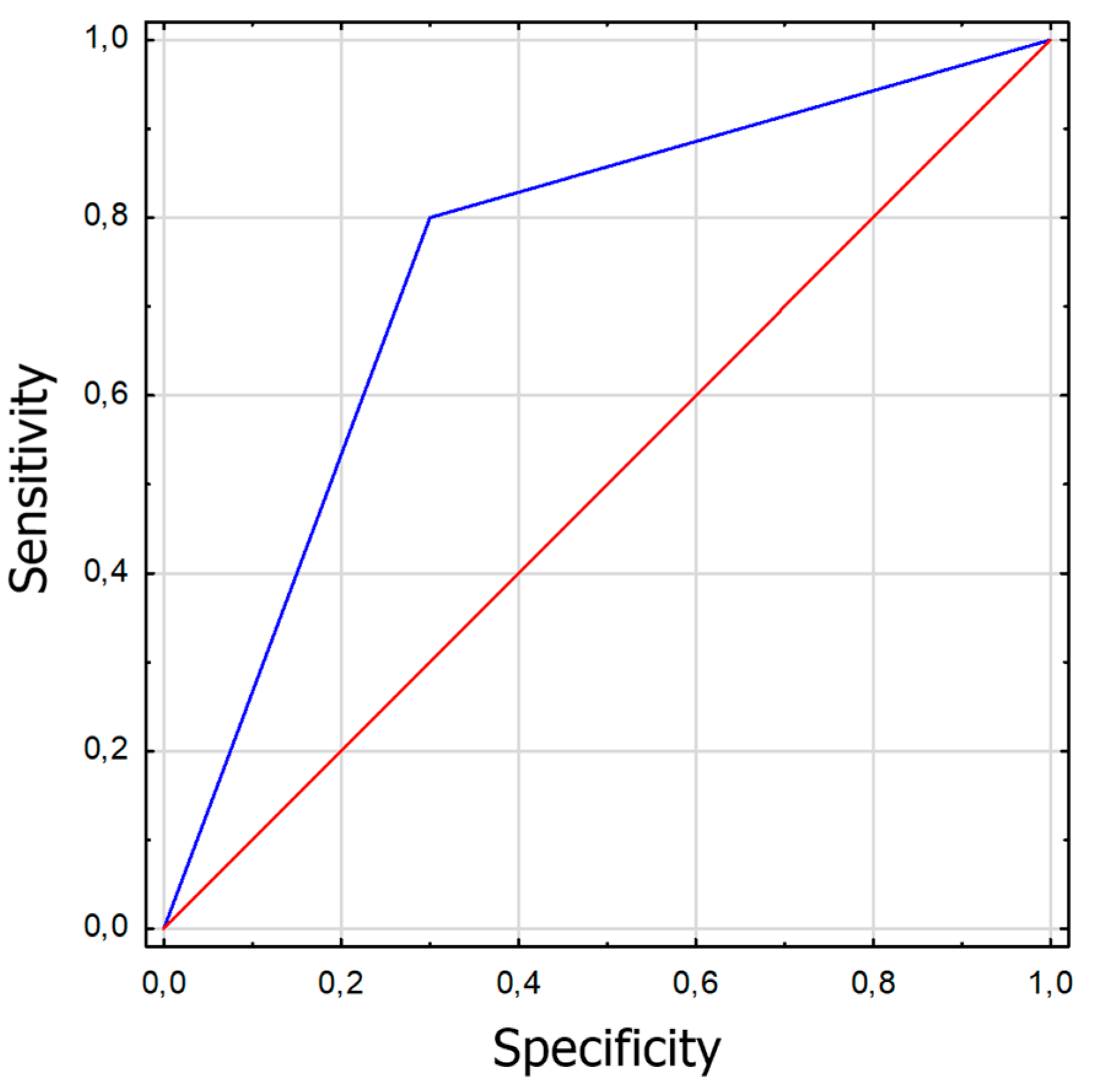
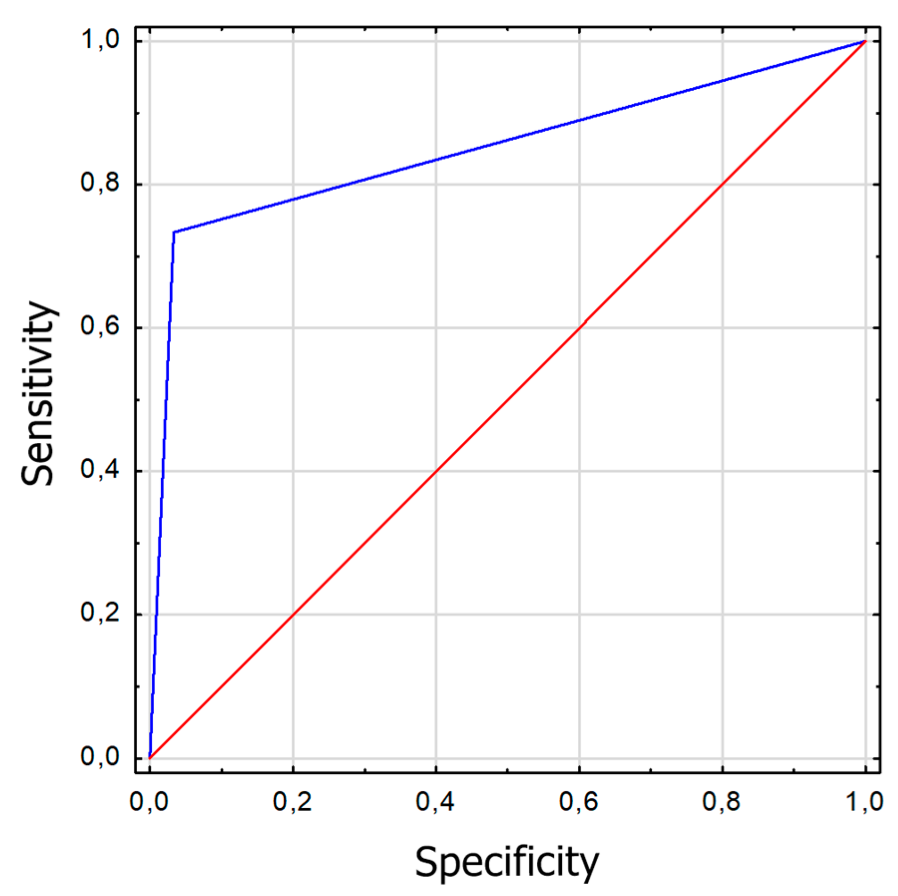
The sensitivity and specificity of strabismus detection were analyzed using the Strabiscan device. A Receiver Operating Characteristic (ROC) curve was calculated along with the Area Under Curve (AUC) (
Figure 1 and
Figure 2).
Discussion
Currently, there is no ideal method for measuring the strabismic angle, although the PCT is the gold standard for the diagnosis of strabismic disease, it is known that the result depends on the examiner's experience and subjective judgment. Obtaining precise results, independent of the experience and skills of the examiner, could lead to better results of surgery on the extraocular muscles since measurements of the strabismus angle are the basis not only for the diagnosis of the type of strabismus, the degree of deviation of the eyeballs, the extent of this deviation, but also on the basis of these measurements the type and extent of surgery on the extraocular muscles is planned.
In our study, we used an innovative demonstration equipment called the Strabiscan. This device has no prism bars, but a precisely adjusted optical system that takes into account refractive correction and the resulting prismatic effect, as well as fully controlled LCD shutters and fixation point (FP) displayed in positions tailored to the individual anatomical features of the patient, and therefore does not have the disadvantages of traditionally used methods and allows standardization of the examination in each patient. Better stabilization of the head on the device in relation to the PCT improves the accuracy and repeatability of the measurement. The fixed measurement resolution of 0.1PD is much higher in contrast to PCT, where stepped prism power resolution is available. In addition, the result of the study is not affected by the psychophysical state of the examiner, and the patient is only limited by the shorter test time. The magnitude of the deviation is observed by the software, not by the operator, so it cannot be affected by the individual operator's experience level and perceptiveness. Another advantage of the Strabiscan device is a fixed obscuration time of 1.5 seconds, and the covered eye is almost fully isolated from ambient light, allowing for more effective fusion breaking than in a standard PCT test using a simple manual occluder. This effect is comparable to the use of one-eye occlusion prior to PCT testing.
The most debatable issue may be the accuracy of the measurements. The PCT itself is the gold standard of testing, but there is no reference method for measuring strabismus angle to which new devices can be compared. As a new device, the Strabiscan does not have a specific measurement accuracy, but this will be the subject of future studies. In our opinion, the best indicator of the accuracy of the Strabiscan would be a study of a large group of patients conducted before and after surgery, planned on the basis of the results from the PCT. The final postoperative result should then be confronted with the difference in strabismus angle readings between the Strabiscan and the PCT, and recalculated whether, hypothetically, a surgery performed according to the strabismus angle readings measured by the Strabiscan would also cover the postoperative strabismus angle.
We presumed that convergence caused by the proximity of the camera may hinder the test, resulting in an overestimation of convergent strabismus and an underestimation of divergent strabismus. Nevertheless, the Strabiscan device successfully attempted to eliminate psychological convergence and the associated distance compression in a virtual environment by displaying a correctly prepared and slightly blurred background image of a landscape with far-field objects on the test screen. Technological difficulties may be encountered if the patient has a large refractive error, i.e., > +/- 10 Diopters (D), or if the patient has nystagmus. Underestimation of the strabismus angle may be encountered in the case of visual field deficits.
A minor technological risk is the imperfect pupil movement detection algorithm, which relies on very accurate detection of the pupil’s position in the image. The exact behavior of the algorithm in the case of very irregular pupils or pupils strongly obstructed by the eyelid during oblique gaze is not known. It should be emphasized that all of the analyzed publications show eye examinations under near ideal conditions, i.e., an accurately visible entire pupil, no shadows, looking at a small angle, while the device we propose should work properly in contact with a variety of individual patients. The answer to these doubts requires further research.
Referring to PCT method, we put forward the thesis that the standard PCT test, in which the patient additionally wears his habitual correction lenses, results in an incorrect reading of the prism bar because, when looking at an angle, the lens border acts as a prismatic element and causes an additional deflection of light rays. We conducted a laboratory experiment indicating that when looking at a FP at a certain large angle, the eyeball angle is noticeably different before and after wearing an additional correction lens. For example, the concave lenses cause an apparent angular narrowing of the FoV of the patient, which in the general case is the result of keeping the lens approximately 10 mm from the corneal front. The PCT method does not determine the correction of the viewing angles of the FP according to the magnitude of the refractive defect. Large values of astigmatism or aberrations of the corrective lenses further complicate the problem. This thesis requires further analysis of the results of strabismic angle measurements of patients wearing corrective lenses. The most relevant may be the results of strabismus surgeries based on traditional diagnostic methods, especially whether there is a statistically significant correlation between the type of refractive defect and the magnitude of surgical strabismic undercorrection.
Currently, the lack of devices such as Strabiscan on the market constitutes a strabismus measurement niche in public and private facilities that treat strabismus, both with behavioral and surgical methods. The proposed device is distinguished by high reliability of the strabismus angle assessment, which may be easily used by ophthalmologists and orthoptists without specialized training courses, which may favor its widespread use in the healthcare system. In the current epidemiological situation related to COVID-19, an additional undoubted advantage of the device is the reduction of close contact with the patient and the possibility of using full personal protective equipment during examinations. Limitations of the current study include the small study group and the inclusion of only Caucasians. So far, results for horizontal strabismus only have been analyzed. It is uncertain when the test can be performed on patients with severe mental disabilities.
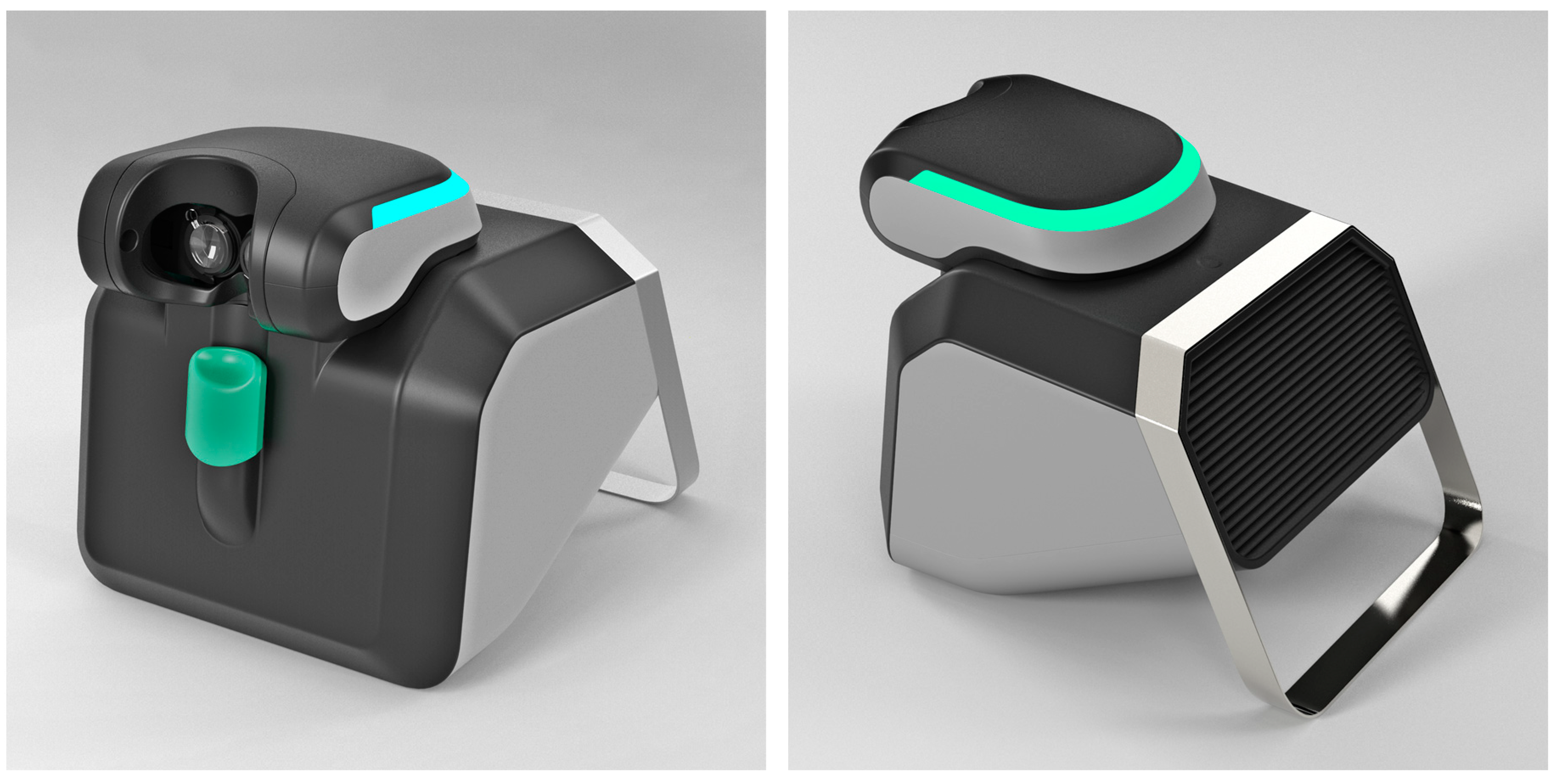
It is worth mentioning that, based on our experience, a project is currently underway to build a commercial version of the Strabiscan device, with a far more advanced optomechanical system and software, which will form the basis for clinical trials and further experimentation (
Figure 3). The project is funded and developed entirely by CX Engineering Ltd. (Balice, Poland) and medical certification of the device and clinical testing is scheduled for the year 2023.
In conclusion, the Strabiscan is a valuable and safe demonstration device that allows quick and objective evaluation of the strabismus angle and as the first in the world able to automatically diagnose strabismic disease by performing a standard cover-uncover test with comparable results to a PCT test. Although the PCT is considered the gold standard it has a significant number of disadvantages and, under certain specific conditions, its indications may be biased within a certain measurement error range. Compared to the PCT, it has a higher sensitivity in detecting low-angle latent strabismus. The use of the Strabiscan device may allow accurate diagnosis of strabismus even in eye-care practices that have not previously specialized in the detection and treatment of strabismic disease, as highly qualified staff are not required to operate it. In addition, it can improve the results of surgical treatment through accurate and reproducible measurement of strabismus angles.
Methods
The proposed device, called Strabiscan, was developed as a technology demonstrator at the 2nd Department of Ophthalmology of the Pomeranian Medical University, Szczecin, Poland. The device performs fully automatic measurements of strabismus angles with a resolution of 0.1 PD of the vertical and horizontal deviation of the eyeballs at near and far fixation. The Strabiscan device uses an advanced mathematical model of FoV and a very accurate eye tracking system to determine strabismus angles, taking into account individual characteristics of a patient, i.e., PD as well as distortions of the FoV, caused by correction lenses. The device was developed as part of the mini-grant Innovation Incubator 4.0, funded by the European Union. The study received a positive opinion from the Bioethics Committee at the Pomeranian Medical University (KB-0012/199/2020). The study protocol was in accordance with the tenets of the Declaration of Helsinki. Each participant in the study gave written consent to participate in the study.
Construction of the device
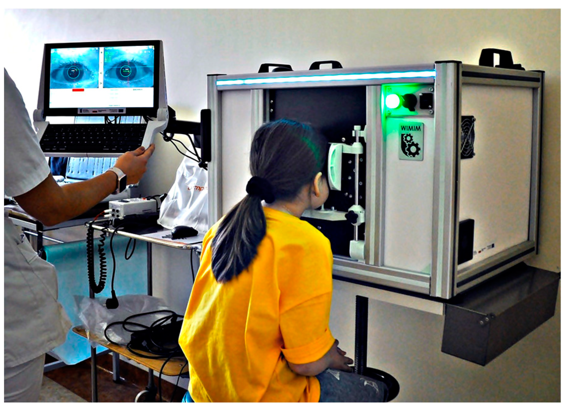
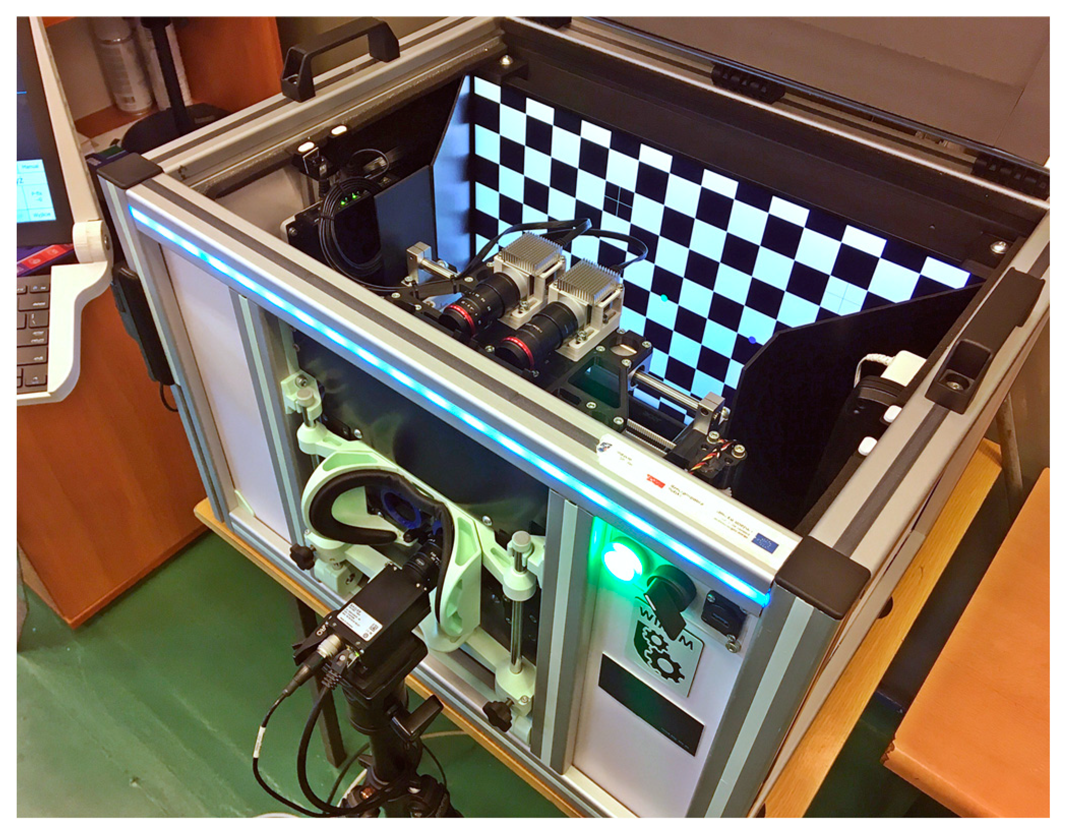
The Strabiscan device, like many other ophthalmic devices, is stationary and integrated into a single housing. When seated, the patient rests his head and chin on a suitably contoured and permanently fixed frame (
Figure 4). In addition, the design of the frame minimizes the amount of scattered ambient light falling on the retina, making it easier to break up binocular fusion.
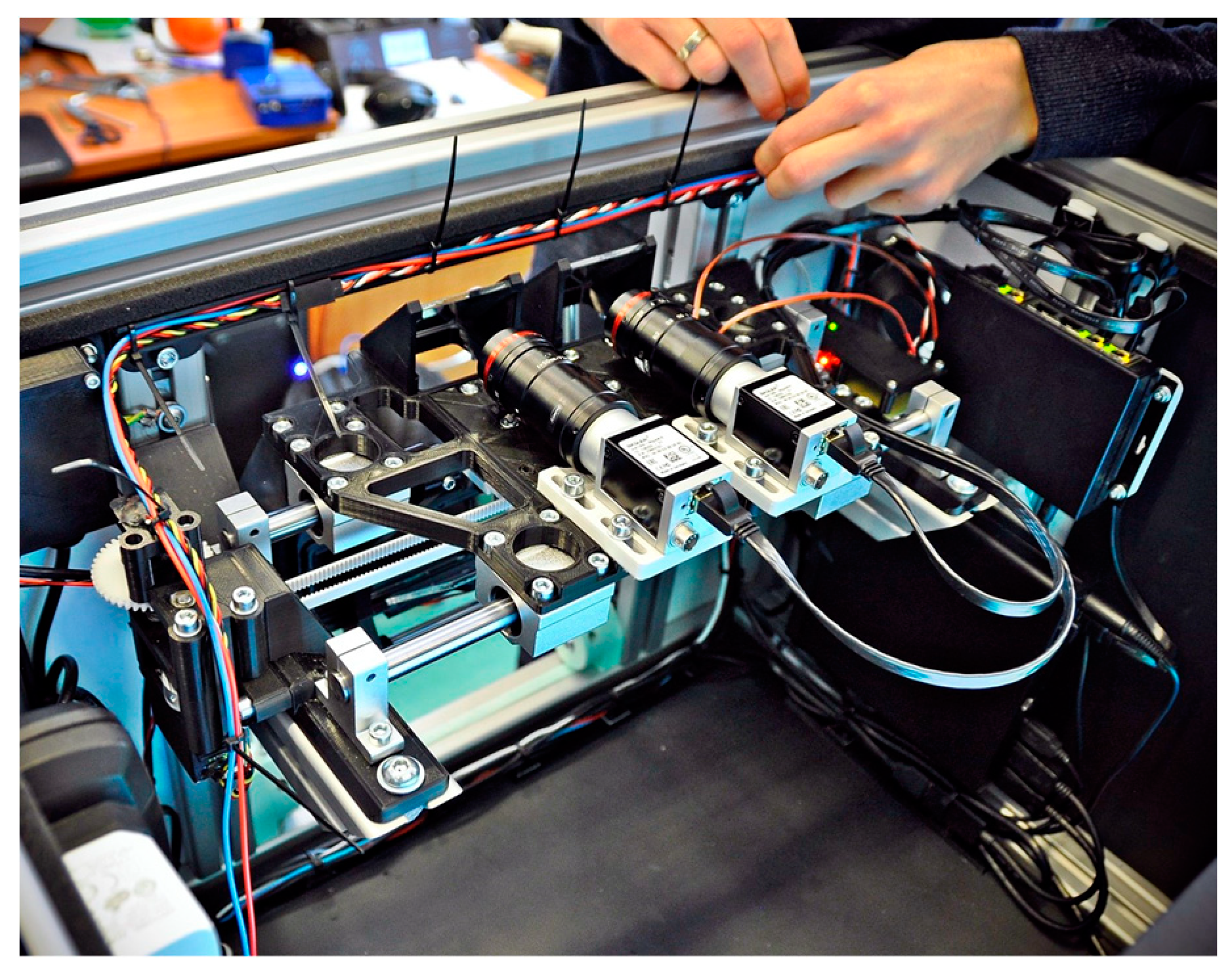
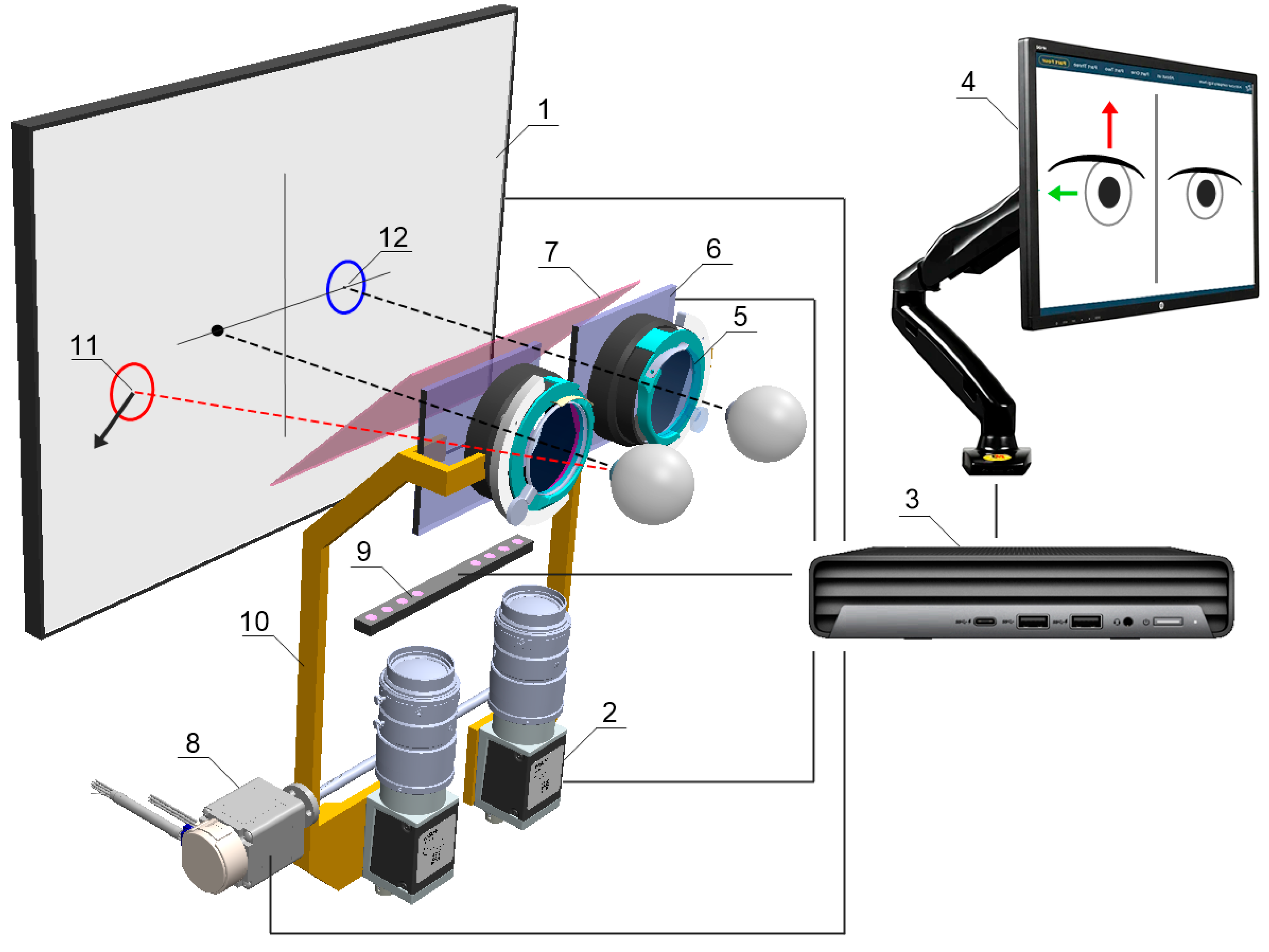
The device is integrated with an operator panel in the form of an additional touchscreen, allowing the operator to control the device, including, i.a. selecting the type of examination, previewing camera images, observing the examination process, or recording and reading records. Internally, the device contains several key components (
Figure 5 and
Figure 6.), including:
24-inch inner test screen for displaying FPs,
two monochromatic cameras Basler acA1300-60gmNIR with dedicated lenses KOWA LM50JC3M2 for NIR spectrum,
trial lens adapter to compensate for spherical defects and enable near and far vision,
a module with two controllable LCD blinds, allowing the selected eye to be covered,
a drive system comprising the Hitec HS-635MG servo motor and an additional reduction gear and transmission belt, allowing the optics to be adjusted to the patient's PD,
glass filter called „hot mirror” measuring 130×80mm, allowing simultaneous observation of the test screen by a patient and observation of pupil movements by the cameras,
linear pupil illuminators based on NIR LEDs.
The cameras, together with the lenses and LCD shutters, form two optomechanical modules, moving oppositely on linear guides by means of the drive system. Such arrangement automatically adjusts the optical axes to the patient's PD prior to the actual examination and allows comfortable observation of the examination screen. The PD can be set from 53 to 82 mm and is taken into account when setting the following FPs positions on the test screen, increasing the reliability of the results in both children and adults. The test screen was installed behind the optomechanical modules and in front of the patient's eyes at a distance of 400 mm.
The physical size of the screen’s working area allows a large part of the patient's FoV (70° horizontally and 40° vertically) to be covered during the examination. The hot mirror is placed close to the patient's eyes at a 45° angle, just behind the LCD shutters, so that its edge is not visible, and the screen image is consistent. A patient looking straight through the hot mirror receives an image of the examination screen in the visible band, while the image of the eye illuminated by infrared LEDs is reflected by the mirror toward the cameras. In addition, the alignment of the left or right camera axis coincides exactly with the left or right eyeball axis, respectively, but the cameras remain invisible to the patient. A highly detailed image of the pupil is obtained, enabling the algorithm to detect setting movements of less than 0.2 mm, difficult to observe during a traditional PCT examination.
NIR illuminators were placed at the periphery of the FoV so that they do not distract the patient during examination, but the iris and pupil are fully illuminated. Standard ring illuminators were rejected due to the numerous round formed reflections making pupil detection more complex.
The cameras, screen, and operator panel are connected to a single mini desktop computer. The servo drive, NIR illuminators, and LCD shutters are controlled from the main application via an Atmega 328p microcontroller, using the UART standard. The LCD shutter switching time is less than 2 ms and remains imperceptible to the patient. The frequency of the PWM signals establishing the shutter state was chosen to avoid flickering during visual observation of the test screen.
Device calibration
Two-stage calibration was carried out before the device was first used.
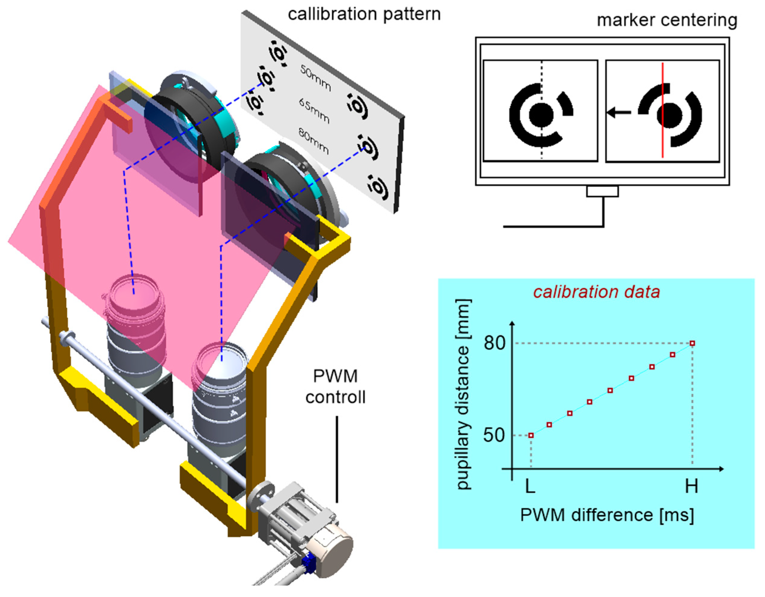
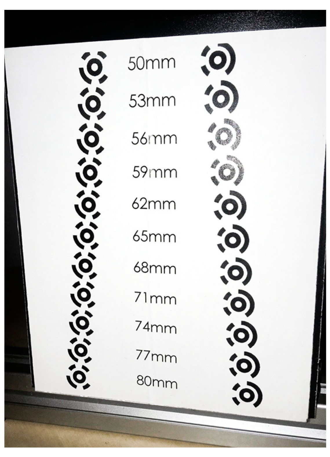
Stage one consisted of determining the relationship between the distance of the optical modules with cameras and the position of the servo drive expressed by PWM signal in the range of 0.9–2.1ms. For calibration purposes, a calibration pattern was designed (
Figure 8), containing an array of eleven optical distance standards for an assumed range of 50–80 mm, which corresponds to the most common PD in humans.
Figure 7.
The idea of centering mechanism calibration for PD adjustments.
Figure 7.
The idea of centering mechanism calibration for PD adjustments.
Figure 8.
Calibration pattern.
Figure 8.
Calibration pattern.
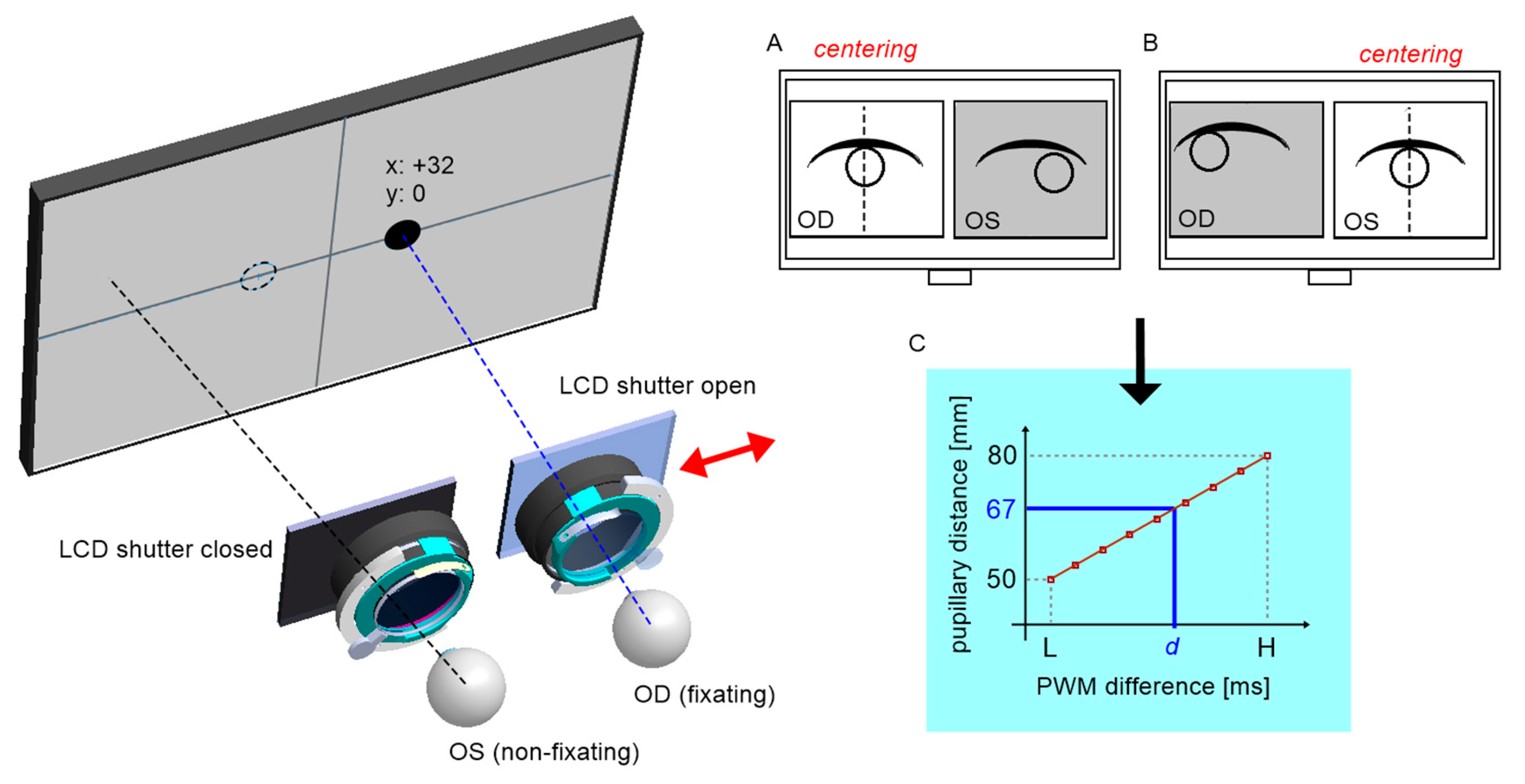
Each pattern is formed by two defined circular coded points. Each camera's axis was pre-aligned mechanically relative to the crosshair target inserted in the trial lens adapter. The procedure then consisted of centring the two markers successively on the left and right camera images and calculating the difference of two servo positions as a function of the pattern distance (
Figure 7). The centring mechanism is based on image feedback, where the deviation for the control system is the horizontal distance from the tracked marker to the image center. Accordingly, the algorithm executes the operation of the proportional controller, where the value of the deviation defines the direction of incrementation of the servo position, and for deviation values close to zero the servo is permanently stopped. The procedure was repeated for each pair of coded points. Aside from slight positioning errors of the servo itself, the determined relationship is approximately linear.
The PD measurement is performed similarly by centring the left and then the right pupil on the images. Using the inverse model obtained from calibration, it is possible to calculate the patient's PD by reading the servo positions.
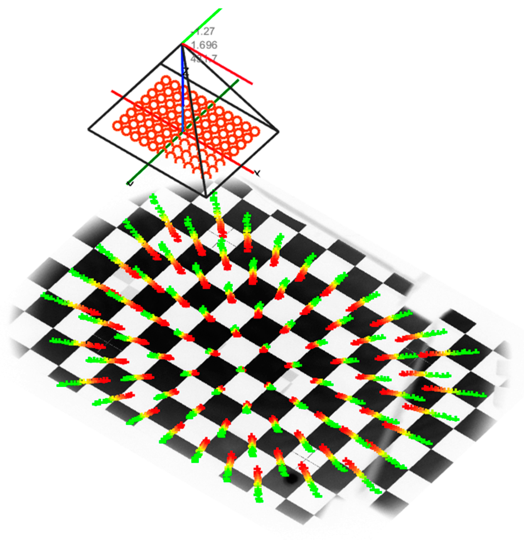
Stage two consisted of building a complex mathematical model to determine the corrections for the vertical and horizontal viewing angles of the FP, depending on the individual spherical defect and the trial lens used for its correction. To determine the model, an external camera was used to observe the test screen from a position normal to the eye. The test screen displayed the calibration pattern in the form of a well-defined regular cheese board. The camera was calibrated internally, and thereafter the extrinsic parameters of the camera in relation to the calibration pattern were established, according to Zhang’s approach which is shown in
Figure 10 (51, 52). Then, for a series of different trial lenses inserted in front of the camera lens, the geometric distortion of the chessboard corners was detected in the captured camera images. Based on the camera model, these corners were inversely projected onto a single normalized Z = 0 plane, as shown in
Figure 9.
By tracking the translations of all corners in the plane, it was possible to determine a series of polynomial radial distortion models. Due to the complexity of this process, workspace modeling for different ocular corrections will be the subject of our original research work.
Fundamentals of measurement techniques
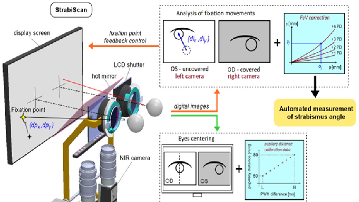
The Strabiscan device performs an automated measurement simulating PCT. During the measurement, the LCD shutters alternate and cycle and display the FP for the left or right eye only, so that binocular vision is permanently disabled. In place of traditional prism bars that deflect the visual path, the device uses algorithms that simulate their operation and move the FP on the test screen surface. Patient’s cooperation is reduced to following and focusing the eye on the FP, which changes its position each cycle. The cameras record and the computer analyses the intensity of the adjusting movements of the uncovered eyeballs.
Each examination is preceded by the automatic centring of the cameras with respect to the axis of the eyeballs (
Figure 11). The patient observes the appearing FP, however, due to the presence of strabismus, the centring must take place for each eye separately. The FP is initially positioned in front of the left eye at a distance of 32 mm from the center of the test screen, and then symmetrically in front of the right eye, which in total corresponds to a typical horizontal PD of 64mm. At the same time, the centring adjustment mechanism is activated. From this point, the viewing path coincides with the optic module axis, and the FP in front of each eye is determined by the centering results.
Within the chosen test, one eye always fixates straight ahead on the static FP. The examined eye observes the FP in a variable position, which is calculated at each switching cycle by the intensity and the direction of the eye adjusting movements in the previous cycle. Thus, the device will automatically attempt to stabilise the position of the FP on the natural optical axis of the strabismic eye, resulting in the stopping of adjusting movements of both eyes.
Figure 12 shows schematically how the strabismic angle is determined vertically and horizontally. Each cycle, the FP position (
ox, oy) is incremented by adding a vector (
dpx, dpy) proportional to the adjusting movement of the eye (
dix, diy) by the determined
Kx and Ky:
The last recorded FP, for which adjusting movements are no longer observed, is corrected by a vector (
cx, cy) determined from the correction model. The resulting apparent FP
p can be described as:
and produces the intersection point of the eye optical axis and the display screen.
As shown in
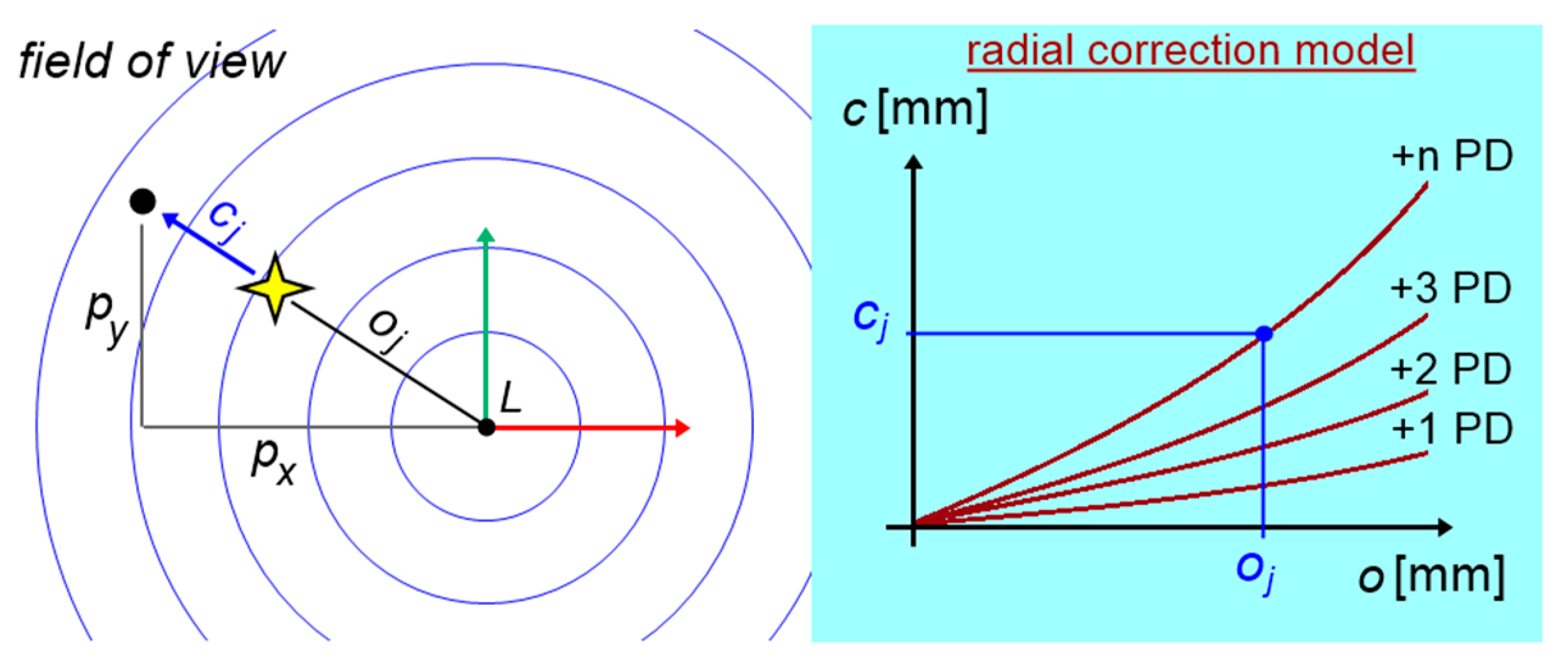
Figure 13, the FoV distortion can be described as a vector
c rotating by a known angle around the focal point
L (or
P), hence a ratio for radial correction:
is always fulfilled. The known eye distance
m from the test screen and the known mm/pixel scale factor of the test screen allow the determination of horizontal and vertical strabismus angles in prismatic diopters, according to the following equations:
When additional +2.5D trial lenses are placed in the device, accommodation is disabled and the strabismic angles can be determined when looking freely at a far distance. The positions and corrections of the FPs are determined relative to the FP L or P straight ahead. By removing the trial lenses, on the other hand, the test can be carried out at a near fixation distance of 40 cm. The positions and corrections of the FPs are determined relative to the center of the screen.
Course of the examination
To evaluate the usefulness of the Strabiscan device, 30 patients aged 5–52 with the manifest strabismic disease were tested with the Strabiscan device and the PCT. The second study group consisted of 30 healthy subjects (aged 5–25). Inclusion criteria for the study were overt horizontal strabismus and age 5-75 years. On the other hand, exclusion criteria were: mental or physical impairment preventing cooperation during the study, age <5 years, age >75 years, refractive defect > ±10D, other eye disease preventing fixation, systemic disease hindering the study, and low visual acuity (<0.1Sn).
A detailed history was taken in all patients and routine ophthalmic examinations were performed, including best-corrected visual acuity to the distance on Snellen charts (optotypes with numbers or pictures, depending on age). Each patient then underwent the PCT. The next test was the evaluation of the strabismus angle using the Strabiscan device. The final examinations were refractive defect evaluation with an autorefractometer (Topcon KR-800, Tokyo, Japan, or Retinomax Righton) after cycloplegia with a drop of 1% cyclopentolate, and biomicroscopic evaluation of the anterior segment of the eye and evaluation of the fundus by indirect ophthalmoscopy using a Volk90D lens or with a Fison ophthalmoscope and a Volk20D lens.
In the device an appropriate set of trial lenses was installed, and the patient was asked to observe the FP on the screen. The device calculated the trial lens for the far distance test according to the results entered into the system from the previous refraction measurement, adding a correction to compensate for the distance between the screen and the patient's eyes (typically +2.5D for a distance of 0.4m). Since the head was placed on the device and until the first test started, the patient could observe the background image monocularly on the screen. By doing so, the patient's interruption of binaural fusion, crucial for relaxing vision and obtaining a correct measurement result, was induced.
Initially, the device performed an automatic pupil-distance test, which involved the patient observing FPs displayed sequentially exactly in front of the left eye and then in front of the right eye. During this time, the optical system adjusted its position so that the central point of the pupil was exactly halfway across the width of the images obtained from the cameras. Then, a strabismus angle test was performed at far fixation and then at near fixation distance, involving the patient's observation of FPs moving automatically on the screen in the vertical and horizontal directions. The system analyzed the fixation movements of both eyes during the alternating covering-uncovering of the eyes. For the near test, this correction (+2.5D) was not applied. Three to five measurements per type of test were taken at a time, depending on the patient's ability to cooperate with the device. A single measurement typically takes between 10 and 30 seconds.
During the examination, the patient was asked to remain in as stable a position when possible. Any slight movement of the patient's head could have been interpreted by the device as an adjustment movement of the eye and could have prevented automatic completion of the examination. This condition was particularly important in pediatric patients. Between measurements, the patient was also asked to hold his or her head against the device, except when changing trial lenses.
Author Contributions
Ewa Grudzińska: Conceptualization, Methodology, Writing – original draft, Data curation, Investigation, Statistical analysis, Magdalena Durajczyk: Investigation, Data curation, Writing – original draft, Marek Grudziński: Software, Validation, Writing – original draft, Visualization, Łukasz Marchewka: Software, Validation, Writing – original draft, Visualization, Monika Modrzejewska: Supervision, Project administration, Conceptualization, Methodology, Writing – review & editing, Formal analysis, Funding acquisition - obtained through a competition – minigrant “Innovation Incubator 4.0”.
Funding
obtained through a competition – minigrant “Innovation Incubator 4.0”.
Institutional Review Board Statement
The study was conducted according to the guidelines of the Declaration of Helsinki. Ethical review and approval were waived, due to complete anonymization of the obtained data.
Informed Consent Statement
Informed consent was obtained from all subjects involved in the study.
Data Availability Statement
The data used to support the findings of this study are available from the corresponding author upon request.
Acknowledgments
The research conducted as part of project: "Innovation Incubator 4.0" in consortium with the Innovation Center of the Maritime University of Szczecin Ltd. under the name MareMed, co-financed by the European Union funds for science, implemented under the Inteligent Development Operational Program (Section 4.4).
Conflicts of Interest
The authors declare that there are no conflicts of interest regarding the publication of this paper.
References
- Pundlik, S.; Tomasi, M.; Liu, R.; Houston, K.; Luo, G. Development and preliminary evaluation of a smartphone app for measuring eye alignment [Internet]. Transl Vis Sci Technol 2019, 8. [Google Scholar] [CrossRef]
- Robaei, D. Factors Associated with Childhood Strabismus. Findings from a Population-Based Study [Internet]. Ophthalmology 2006, 113, 1146–1153. [Google Scholar] [CrossRef] [PubMed]
- von Bartheld CS, Croes SA, Johnson LA. Chapter 59 - Strabismus [Internet]. In: Levin LA, Albert DM eds. Ocular Disease. Edinburgh: W.B. Saunders; 2010:454–460. Saunders; 2010.
- Michaelides, M.; Moore, A.T. The genetics of strabismus [Internet]. J Med Genet 2004, 41, 641–646. [Google Scholar] [CrossRef]
- Jrbashyan, N. et al. Pattern and prevalence of eye disorders and diseases in school-aged children: Findings from the Nationwide School Sight Sampling Survey in Armenia [Internet]. BMJ Open Ophthalmol 2022, 7, 899. [Google Scholar] [CrossRef]
- Valente, T.L.A.; de Almeida, J.D.S.; Silva, A.C.; Teixeira, J.A.M.; Gattass, M. Automatic diagnosis of strabismus in digital videos through cover test [Internet]. Comput Methods Programs Biomed 2017, 140, 295–305. [Google Scholar] [CrossRef] [PubMed]
- Chen, Z.H.; Fu, H.; Lo, W.L.; Chi, Z.; Xu, B. Eye-tracking-aided digital system for strabismus diagnosis [Internet]. Healthc Technol Lett 2018, 5, 1–6. [Google Scholar] [CrossRef] [PubMed]
- Yehezkel, O.; Belkin, M.; Wygnanski-Jaffe, T. Automated Diagnosis and Measurement of Strabismus in Children [Internet]. Am J Ophthalmol 2020, 213, 226–234. [Google Scholar] [CrossRef]
- Schutte, S.; Polling, J.R.; van der Helm, F.C.T.; Simonsz, H.J. Human error in strabismus surgery: Quantification with a sensitivity analysis [Internet]. Graefe’s Archive for Clinical and Experimental Ophthalmology 2009, 247, 399–409. [Google Scholar] [CrossRef]
- Schuster, AK. et al. Health-related quality of life and mental health in children and adolescents with strabismus - Results of the representative population-based survey KiGGS [Internet]. Health Qual Life Outcomes 2019, 17. [Google Scholar] [CrossRef]
- Joo, K.S.; Koo, H.; Moon, N.J. Measurement of strabismic angle using the distance Krimsky test. [Internet]. Korean J Ophthalmol 2013, 27, 276–281. [Google Scholar] [CrossRef]
- Rosenbaum AL, Santiago APauline. Clinical strabismus management : principles and surgical techniques1999, 569.
- Yang, HK. et al. Assessment of binocular alignment using the three-dimensional Strabismus Photo Analyzer [Internet]. British Journal of Ophthalmology 2012, 96, 78–82. [Google Scholar] [CrossRef] [PubMed]
- Choi, R.Y.; Kushner, B.J. The accuracy of experienced strabismologists using the Hirschberg and Krimsky tests [Internet]. Ophthalmology 1998, 105, 1301–1306. [Google Scholar] [CrossRef] [PubMed]
- Rainey, B.B.; Schroeder, T.L.; Goss, D.A.; Grosvenor, T.P. Reliability of and comparisons among three variations of the alternating cover test [Internet]. Ophthalmic and Physiological Optics 1998, 18, 430–437. [Google Scholar] [CrossRef]
- Wright KW, Spiegel PH, Hengst TC. Pediatric ophthalmology and strabismus.. Springer; 2013:.
- De Jongh, E.; Leach, C.; Tjon-Fo-Sang, M.J.; Bjerre, A. Inter-examiner variability and agreement of the alternate prism cover test (APCT) measurements of strabismus performed by 4 examiners [Internet]. Strabismus 2014, 22, 158–166. [Google Scholar] [CrossRef] [PubMed]
- Yeh, P.H.; Liu, C.H.; Sun, M.H.; Chi, S.C.; Hwang, Y.S. To measure the amount of ocular deviation in strabismus patients with an eye-tracking virtual reality headset [Internet]. BMC Ophthalmol 2021, 21. [Google Scholar] [CrossRef]
- Moon HS. et al. Usefulness of virtual reality-based training to diagnose strabismus [Internet]. Sci Rep 2021, 11. [CrossRef]
- Pateras, E.S.; Pateras, E. Technique for Measuring Strabismus with Synoptophore-Review Eye Accommodation-Binocular vision View project Myopia-Corneal topography View project Technique for Measuring Strabismus with Synoptophore-Review [Internet]. Asian Journal of Research and Reports in Ophthalmology 2020, 3, 6–12. [Google Scholar]
- Dallyson Sousa de Almeida, J.; Corrĉa Silva, A.; Cardoso de Paiva, A.; Antonio Meireles Teixeira, J. Computational methodology for automatic detection of strabismus in digital images through Hirschberg test. Comput Biol Med 2012, 42, 135–146. [Google Scholar] [CrossRef]
- Weber, KP. et al. Strabismus Measurements with Novel Video Goggles [Internet]. Ophthalmology 2017, 124, 1849–1856. [Google Scholar] [CrossRef]
- Chopra, R.; Mulholland, P.J.; Tailor, V.K.; Anderson, R.S.; Keane, P.A. Use of a binocular optical coherence tomography system to evaluate strabismus in primary position [Internet]. JAMA Ophthalmol 2018, 136, 811–817. [Google Scholar] [CrossRef]
- Yang, H.K.; Seo, J.M.; Hwang, J.M.; Kim, K.G. Automated analysis of binocular alignment using an infrared camera and selective wavelength filter [Internet]. Invest Ophthalmol Vis Sci 2013, 54, 2733–2737. [Google Scholar] [CrossRef] [PubMed]
- Zou, L. et al. Effectiveness and repeatability of eye-tracking-based test in strabismus measurement of children [Internet]. Semin Ophthalmol 2022, 37, 502–508. [Google Scholar] [CrossRef] [PubMed]
- Bindiganavale, M.; Buickians, D.; Lambert, S.R.; Bodnar, Z.M.; Moss, H.E. Development and Preliminary Validation of a Virtual Reality Approach for Measurement of Torsional Strabismus [Internet]. Journal of Neuro-Ophthalmology 2022, 42, E248–E253. [Google Scholar] [CrossRef] [PubMed]
- Cheng, W. et al. A smartphone ocular alignment measurement app in school screening for strabismus [Internet]. BMC Ophthalmol, 2021; 21. [Google Scholar] [CrossRef]
- Oltrup, T. et al. A new digitised screen test for strabismus measurement. Z Med Phys [published online ahead of print: August 10, 2022]. [CrossRef]
- Ping Liang; Feng Pan; Qiwei Gu. Intelligent type digital type synoptophore2010.
- Huang, X.; Lee, S.J.; Kim, C.Z.; Choi, S.H. An automatic screening method for strabismus detection based on image processing [Internet]. PLoS One 2021, 16, 642–650. [Google Scholar]
- Zheng, Y. Intelligent evaluation of strabismus in videos based on an automated cover test [Internet]. Applied Sciences (Switzerland) 2019, 9, 731. [Google Scholar] [CrossRef]
- Zheng, Y.; Fu, H.; Li, B.; Lo, W.L.; Wen, D. An Automatic Stimulus and Synchronous Tracking System for Strabismus Assessment based on Cover Test. 2018 International Conference on Intelligent Informatics and Biomedical Sciences, ICIIBMS 2018 2018, 123–127.
- Mao, K. et al. An artificial intelligence platform for the diagnosis and surgical planning of strabismus using corneal light-reflection photos [Internet]. Ann Transl Med 2021, 9, 374–374. [Google Scholar] [CrossRef]
- Chen, Z.; Fu, H.; Lo, W.L.; Chi, Z. Strabismus Recognition Using Eye-Tracking Data and Convolutional Neural Networks [Internet]. J Healthc Eng 2018, 2018, 7692198. [Google Scholar] [CrossRef]
- Mestre, C.; Otero, C.; Díaz-Doutón, F.; Gautier, J.; Pujol, J. An automated and objective cover test to measure heterophoria [Internet]. PLoS One 2018, 13, e0206674. [Google Scholar] [CrossRef]
- Metsing, T.I.; Mathebula, S.D. Comparative analysis of Modified Thorington to the prism cover, von Graefe and Maddox rod tests. African Vision and Eye Health 2022, 81. [Google Scholar] [CrossRef]
- Miao, Y.; Jeon, J.Y.; Park, G.; Park, S.W.; Heo, H. Virtual reality-based measurement of ocular deviation in strabismus [Internet]. Comput Methods Programs Biomed 2020, 185. [Google Scholar] [CrossRef] [PubMed]
- Qiwei Gu; Ping Liang; Feng Pan. Intelligent type digital type synoptophore2009.
- Schutte Sander; Geukers Elisabeth Bouwina Margaretha; Simonsz Huibert Jan; Van Der Helm Franciscus Cornelis Theodorus. APPARATUS AND METHOD FOR AUTOMATICALLY DETERMINING A STRABISMUS ANGLE2011.
- Ziyu Tglbhyczlsl. Strabismus degree calculation method based on eccentric photography2019.
- Maor Ron Uriel; Barnard Nigel Andrew Simon; Yashiv Yuval. STRABISMUS DETECTION2014.
- Yu, D. Strabismus training device2021.
- Du Yu; Hu Feiyang. Strabismus measurement equipment2021.
- Wilhelm Vdb. METHOD, SYSTEM AND COMPUTER READABLE MEDIUM TO DETERMINE A STRABISMUS ANGLE BETWEEN THE EYES OF AN INDIVIDUAL2017.
- Juntao Wtfqyzz. Human eye strabismus direction and strabismus degree measurement deviceNo Title2020.
- Heo Hwan; Park Gyu Hae; Yinan Miao; Jeon Jun Young. DEVICE AND METHOD FOR MEASURING STRABISMUS ANGLE2020.
- Hamish M. HEAD MOUNTABLE DEVICE FOR MEASURING EYE MOVEMENT HAVING VISIBLE PROJECTION MEANS2016.
- Macdougall Hamish; Weber Konrad P; Andersen Anders Thøsing; Kopilewicz Izaak. Head mountable device for measuring eye movement2017.
- Wenchao Wywmg. Strabismus correction vision imaging device based on VR technology202.
- Weilin Fhlslbl. Digital strabismus diagnosis method, device and system2019.
- Zhang, Z. Flexible camera calibration by viewing a plane from unknown orientations. Proceedings of the IEEE International Conference on Computer Vision 1999, 1, 666–673. [Google Scholar]
- Zhang, Z. A flexible new technique for camera calibration. IEEE Trans Pattern Anal Mach Intell 2000, 22, 1330–1334. [Google Scholar] [CrossRef]
Figure 1.
ROC graph for Strabiscan at near fixation. Sensitivity = 0,8; Specificity = 0,7; AUC = 0,75 (p<0,001).
Figure 1.
ROC graph for Strabiscan at near fixation. Sensitivity = 0,8; Specificity = 0,7; AUC = 0,75 (p<0,001).
Figure 2.
ROC graph for Strabiscan at far fixation. Sensitivity = 0,73; Specificity = 0,97; AUC = 0,85 (p<0,001).
Figure 2.
ROC graph for Strabiscan at far fixation. Sensitivity = 0,73; Specificity = 0,97; AUC = 0,85 (p<0,001).
Figure 3.
Rendered model of a commercial version of Strabiscan device.
Figure 3.
Rendered model of a commercial version of Strabiscan device.
Figure 4.
Strabiscan in the phase of pilot testing in clinical conditions involving pediatric patients.
Figure 4.
Strabiscan in the phase of pilot testing in clinical conditions involving pediatric patients.
Figure 5.
Strabiscan device during assembly; the transmission drive components, camera system and ethernet switch are visible.
Figure 5.
Strabiscan device during assembly; the transmission drive components, camera system and ethernet switch are visible.
Figure 6.
Schematic concept of the Strabiscan device. The numbers are labeled consecutively: 1) fixation points display screen, 2) NIR camera, 3) PC, 4) operator’s control panel, 5) adapter for trial lenses, 6) LCD shutters, 7) hot mirror, 8) drive system allowing the optics to be adjusted to the patient's PD, 9) NIR LED illuminator, 10) movable fixing element for optical components, 11) FP for the non-fixing eye, 12) FP for the fixing eye.
Figure 9.
FoV distortion model, normalized to the plane of the calibration standard, obtained in Matlab software.
Figure 9.
FoV distortion model, normalized to the plane of the calibration standard, obtained in Matlab software.
Figure 10.
Calibration procedure on the device using an external camera to observe FoV changes.
Figure 10.
Calibration procedure on the device using an external camera to observe FoV changes.
Figure 11.
Idea of the PD calculation, by centering alternately the uncovered right eye (A) and the left eye (B) and using the calibration model (C).
Figure 11.
Idea of the PD calculation, by centering alternately the uncovered right eye (A) and the left eye (B) and using the calibration model (C).
Figure 12.
Idea of the strabismus angle calculation for ceasing of eye adjusting movements. A) The right eye (OD) fixates on the immovable FP, while the left eye (OS) is covered and the camera records its position in the image. The FP coordinates for OS are initially predefined (it can be either center of the FoV or any given point on the display screen). B) The OS is uncovered and makes an adjusting move towards appearing FP, while the left camera records the amount and direction {dix, diy} of this move. The first cycle ends. C) The OS is covered, and the OD fixates on the immovable FP again. At the same time, the system calculates a new displacement {dpx, dpy} of the FP for the OS in proportion to the adjusting move, recorded in the previous cycle. D) The FP for the OS appears in the screen in the new position {Ox, Oy}. The OS is uncovered and makes an adjusting move, recorded again by the left camera. The second cycle ends. The sequence repeats until FPs reach stable positions in the natural visual axes for both eyes, i.e. vector of adjusting movement is sufficiently small (<4 pixels). Based on the distortion model of the FoV, the corrected position {px, py} of the apparent FP is determined, and the strabismus angle is calculated.
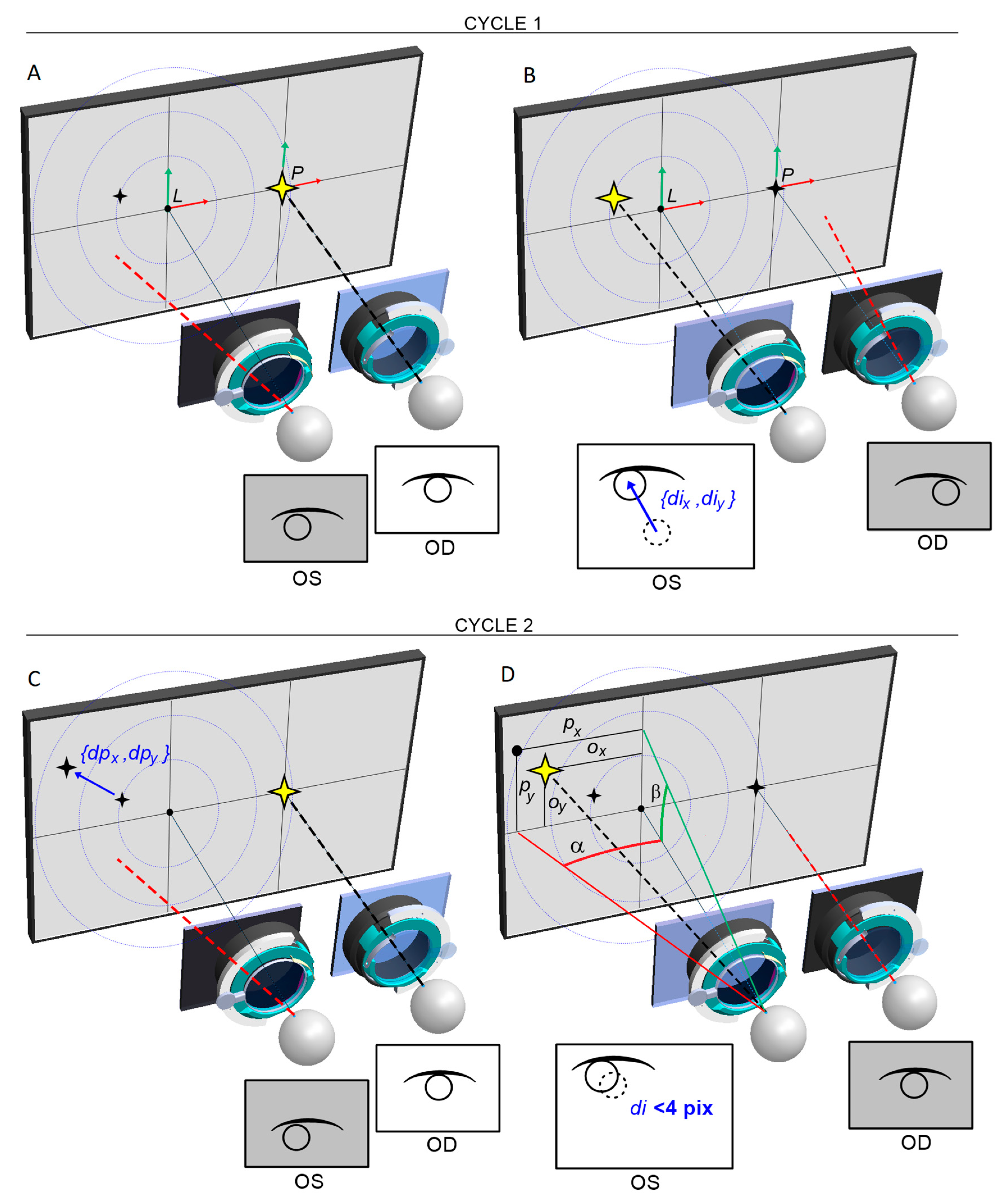
Figure 13.
Determination of apparent FP based on the radial correction model for spherical lenses.
Figure 13.
Determination of apparent FP based on the radial correction model for spherical lenses.
Table 1.
Characteristics of the study groups.
Table 1.
Characteristics of the study groups.
| |
Study group n=30 |
Group of healthy subjects n=30 |
| Age |
16,65 ± 11,47 |
10,20 ± 3,84 |
| Gender (F:M) |
14: 16 |
17: 13 |
| Body height |
1,56 ± 0,19 |
1,41 ± 0,14 |
| Body weight |
53,98 ± 22,32 |
37,37 ± 12,55 |
| Prematurity |
4 (13,3%) |
1 (3,3%) |
| Burdened perinatal history |
5 (16,7%) |
0 (0%) |
| Systemic diseases |
9 (30%) |
1 (3,3%) |
Table 2.
Features regarding diagnosis and treatment of strabismus in the study group.
Table 2.
Features regarding diagnosis and treatment of strabismus in the study group.
| Feature |
Mean |
SD |
Min |
Max |
| Age of diagnosis of strabismus |
3,35 |
3,11 |
0,00 |
12,00 |
| Time since diagnosis of strabismus |
13,33 |
13,24 |
1,00 |
52,00 |
| Treatment time for strabismus |
10,80 |
11,78 |
1,00 |
45,00 |
| |
n |
% |
|
|
| Satisfaction with eyeglass treatment |
17/30 |
60,7 |
|
|
| Willingness to have faster strabismus surgery |
17/30 |
60,7 |
|
|
| Use of orthoptic rehabilitation |
24/30 |
80,0 |
|
|
| Satisfaction with orthoptic rehabilitation |
18/30 |
69,2 |
|
|
| Undergoing eye surgery |
15/30 |
50,0 |
|
|
| Strabismus surgery performed |
14/30 |
46,7 |
|
|
| Strabismus in the family |
9/30 |
30,0 |
|
|
| Ophthalmic disease in the family |
8/30 |
26,7 |
|
|
Table 3.
Comparison of eyes deviations and inconvenience of the examination for the patient performed with the listed methods.
Table 3.
Comparison of eyes deviations and inconvenience of the examination for the patient performed with the listed methods.
| |
Mean ±SD |
Min - Max |
Median |
Quartiles 25% - 75% |
p |
| Eye deviation in the PCT test at far fixation [PD] |
-5,9 ±13,1 |
-40,0 - 30,0 |
0,0 |
-11,0 - 0,0 |
0,218 |
| Eye deviation in the Strabiscan test at far fixation [PD] |
-4,2 ±14,3 |
-44,3 - 39,8 |
-0,6 |
-10,4 - 2,2 |
| Eye deviation in the PCT test at near fixation [PD] |
-7,2 ±14,9 |
-51,0 - 35,0 |
-4,0 |
-12,0 - 0,0 |
0,923 |
| Eye deviation in the Strabiscan test at near fixation [PD] |
-6,9 ±14,6 |
-49,1 - 33,8 |
-3,9 |
-11,4 - 1,2 |
| Inconvenience of examination PCT |
2,28 ±1,95 |
1,00 - 10,00 |
1,00 |
1,00 - 3,00 |
0,531 |
| Inconvenience of examination Strabiscan |
2,04 ±1,82 |
1,00 - 8,00 |
1,00 |
1,00 - 2,00 |
|
Disclaimer/Publisher’s Note: The statements, opinions and data contained in all publications are solely those of the individual author(s) and contributor(s) and not of MDPI and/or the editor(s). MDPI and/or the editor(s) disclaim responsibility for any injury to people or property resulting from any ideas, methods, instructions or products referred to in the content. |
© 2023 by the authors. Licensee MDPI, Basel, Switzerland. This article is an open access article distributed under the terms and conditions of the Creative Commons Attribution (CC BY) license (http://creativecommons.org/licenses/by/4.0/).
