1. Introduction
There is a great interest in the usage of ultrasonic guided waves (UGW)-based Structural Health Monitoring (SHM) techniques in the aeronautics industry for detecting, locating, and evaluating damages in composite structures [
1,
2,
3]. These SHM techniques offer real-time monitoring capabilities, improving safety, accuracy, and significantly reducing maintenance time and costs compared to traditional non-destructive techniques (NDT) such as visual inspection, ultrasonic A-/C-scans, X-ray, thermography, and infrared techniques [
4,
5,
6].
UGW propagation is advantageous for SHM due to its ability to travel long distances with minimal attenuation and its sensitivity to small structural defects [
7,
8]. Lead zirconate titanate (PZT) transducers are commonly used in active sensing SHM techniques because of their durability, lightweight nature, relatively low cost, and low power consumption [
9]. These PZT transducers can be surface-mounted or embedded within composite structures [
10]. However, surface-mounted transducers may be susceptible to damage from external loading, and the thickness and external environments can affect measurement results [
11,
12]. Additionally, the anisotropic properties of composite structures make it challenging to predict their structural behaviour under complex multi-directional loading conditions using surface-mounted PZT transducers [
13]. Embedded PZT transducers offer improved durability and reliability, especially in thick composite structures [
14].
Various methods have been proposed for embedding PZT transducers, including conventional insertion and cut-out techniques [
15,
16], as well as the use of SMART LayersTM [
17,
18] and circuit-printing techniques [
19,
20,
21]. However, limited research has focused on studying the effects of embedded PZT transducers within different layers of thick composites.
Some studies have investigated the detection of low-energy impact damage using surface-mounted or embedded PZT transducers, showing that closer proximity to the surface improves the sensitivity [
22]. Analytical approaches have also been proposed to investigate the deformation of composite laminates actuated by surface-mounted and embedded PZT transducers, demonstrating reduced deflection with increased embedded depth of the transducers [
23]
. Additionally, the deformation induced by surface-mounted transducers was found to be larger than that of embedded transducers.
The objective of this paper is to study guided waves through different layers of composites using surface-mounted and embedded PZT transducers. Numerical simulations will be conducted to study the guided wave behaviour first. The peak amplitude of the first wave packet and the time-of-flight (ToF) activated/received by PZT transducers at different placing positions will be investigated. After that, UGW propagation through different layers of composite coupons will be experimentally studied.
2. Finite-element Modelling
2.1. Numerical Simulation
To investigate the thickness effect of different embedded positions on ultrasonic guided waves (UGW), numerical simulations were conducted. The focus was on understanding the relationship between the peak amplitude of the first wave packet and the time-of-flight (ToF) of UGW for composites with different thicknesses (2 mm, 4 mm, and 9 mm). In numerical calculations, direct time-integration methods employing explicit and implicit algorithms were utilized [
24]. The explicit algorithm, which is conditionally stable, relies entirely on the results of the previous time step (t) to determine the equilibrium state at the subsequent time step (t + ∆t) [
24]. It should be noted that the explicit algorithm is more computationally efficient for larger models compared to the implicit algorithm [
25].
However, the explicit time integration algorithm described in [
26] is specifically designed for surface-mounted PZT transducers, and there is no analytical solution available for embedded PZT transducers using the explicit algorithm within the context of Abaqus/Explicit dynamic analysis. Additionally, the Abaqus/Explicit dynamic analysis lacks a piezoelectric element, further limiting its applicability for simulating UGW propagation in composite laminates with embedded PZT transducers. Consequently, the implicit dynamic analysis (Abaqus/Standard) becomes the sole viable approach for simulating UGW propagation in composite laminates with embedded PZT transducers. To utilize this approach effectively, the piezoelectric matrix and the dielectric parameters (permittivity) for the PZT transducer need to be validated in advance.
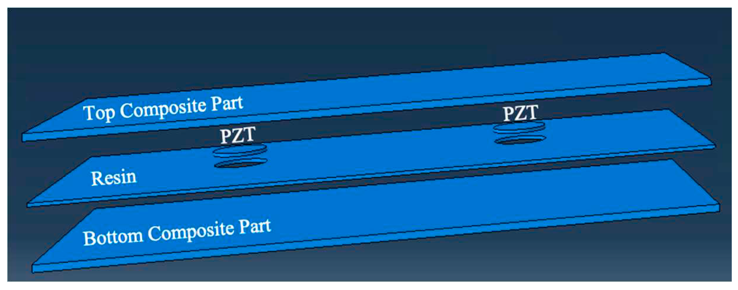
Figure 1 illustrates the assembly relationships of the composite structures with embedded PZT transducers using the commercial software ABAQUS. In each model, two PZT transducers were either surface-mounted or embedded into the composite panels, positioned from the first layer to the middle layer.
To achieve different thicknesses in the composite parts, the overall size of the part was set to 0.22 m × 0.17 m. The depths of each model were defined as 0.002 m, 0.004 m, and 0.009 m, respectively. The PZT transducer had a diameter of 0.01 m and a thickness of 0.0002 m. To fill the gap in the middle section, a resin part with the same dimensions as the composite part was included. The thickness of the resin part was set to 0.0002 m. The distance between the two PZT transducers was 0.11 m, and their distances from the centre to the edges were 0.055 m in the x-direction and 0.085 m in the y-direction. For the definition of the composite lay-up, the element type was chosen as continuum shell. The stacking sequences and the single thickness of each ply were [(0°/+45°/-45°/+90°)n]s, where n represents the number of plies (2, 4, or 9), and the single ply thickness was set to 0.000125 m.
In summary, due to limitations in the explicit algorithm and the absence of piezoelectric elements in Abaqus/Explicit, the implicit dynamic analysis (Abaqus/Standard) is the preferred numerical method for simulating UGW propagation in composite laminates with embedded PZT transducers. The assembly relationships of the composite structures with embedded PZT transducers were defined in ABAQUS, including the sizes and positions of the transducers, the thicknesses of the composite and resin parts, and the stacking sequences and thicknesses of the plies. These parameters provide the basis for further analysis and simulation of the UGW behaviour in the composite structures.
Material properties for unidirectional carbon fibre prepregs, the PZT actuator and the resin are listed in
Table 1. The piezoelectric and the dielectric parameters used for the implicit dynamic analysis can be found in
Table 1. For meshing the composite part, an element size of 0.001 m was used in the x-y plane, and only one element was employed in the z-direction. The family type was set as a continuum shell, and the element type chosen was SC8R in the mesh control. The diameter of the PZT transducer was 0.01 m, and the thickness was 0.0002 m. For meshing the PZT actuator, an element size of 0.0005 m was used in all directions. The family type was set as piezoelectric, and the element type chosen was an 8-node linear piezoelectric brick (C3D8E). For meshing the resin, the setups for the element size and mesh control were the same as those used for the composite part and 3D stress, C3D8R.
To verify the time step of the signal, the increment size of the period was set to 2e-8 by selecting the "fixed" type and "unlimited" by choosing the "automatic" type under the incrementation window in the STEP procedure. It was observed that there was no difference in the results between these two different settings. For the implicit dynamic procedure, the frequency was set to every n increments (n=10). This means that the analysis would capture data and update the results every 10 time steps. The input signal of the electrical potential used for the implicit dynamic analysis (Abaqus/Standard) was a chirp signal, which is a signal that sweeps through a frequency range [
27]. The frequency range of the chirp signal was set from 25 kHz to 500 kHz. The time duration of the signal was 200 μs, and the input amplitude was 6 V.
2.2. Results
2.2.1. Envelop Signals
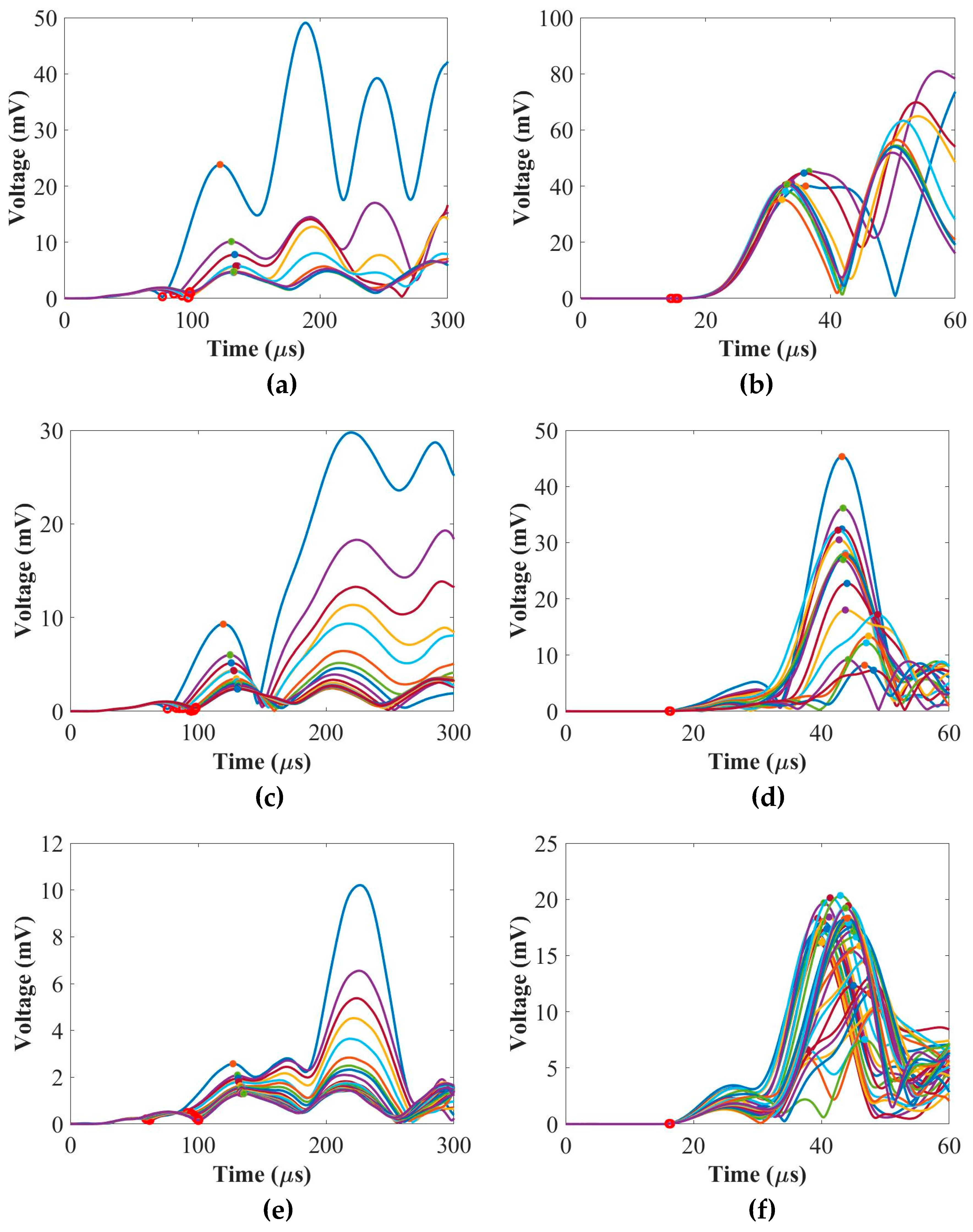
The chirp signals obtained were reconstructed into five-cycle Hanning-windowed toneburst signals at 50 kHz and 250 kHz. These toneburst signals were used to analyze the envelope signals of the ultrasonic guided waves (UGW) through the composite panels. The envelope signals were computed using the Hilbert transform, a mathematical tool commonly used for signal processing and envelope detection.
Figure 2 provides a summary of the numerical envelope signals of UGW for the composite panels with thicknesses of 2 mm, 4 mm, and 9 mm, placed in different positions. The envelope signals were generated at 50 kHz and 250 kHz. From these signals, the time-of-flight (ToF) and the peak amplitude of the envelope signals (corresponding to the first wave packet of UGW) were calculated for each signal. The results presented in
Figure 2 offer insights into the behaviour of the UGW through the composite panels of varying thicknesses and different placements. The ToF provides information about the time it takes for the UGW to travel through the panel, while the peak amplitude of the envelope signals indicates the strength or intensity of the UGW at the first wave packet.
2.2.2. Time-of-Flight (ToF)
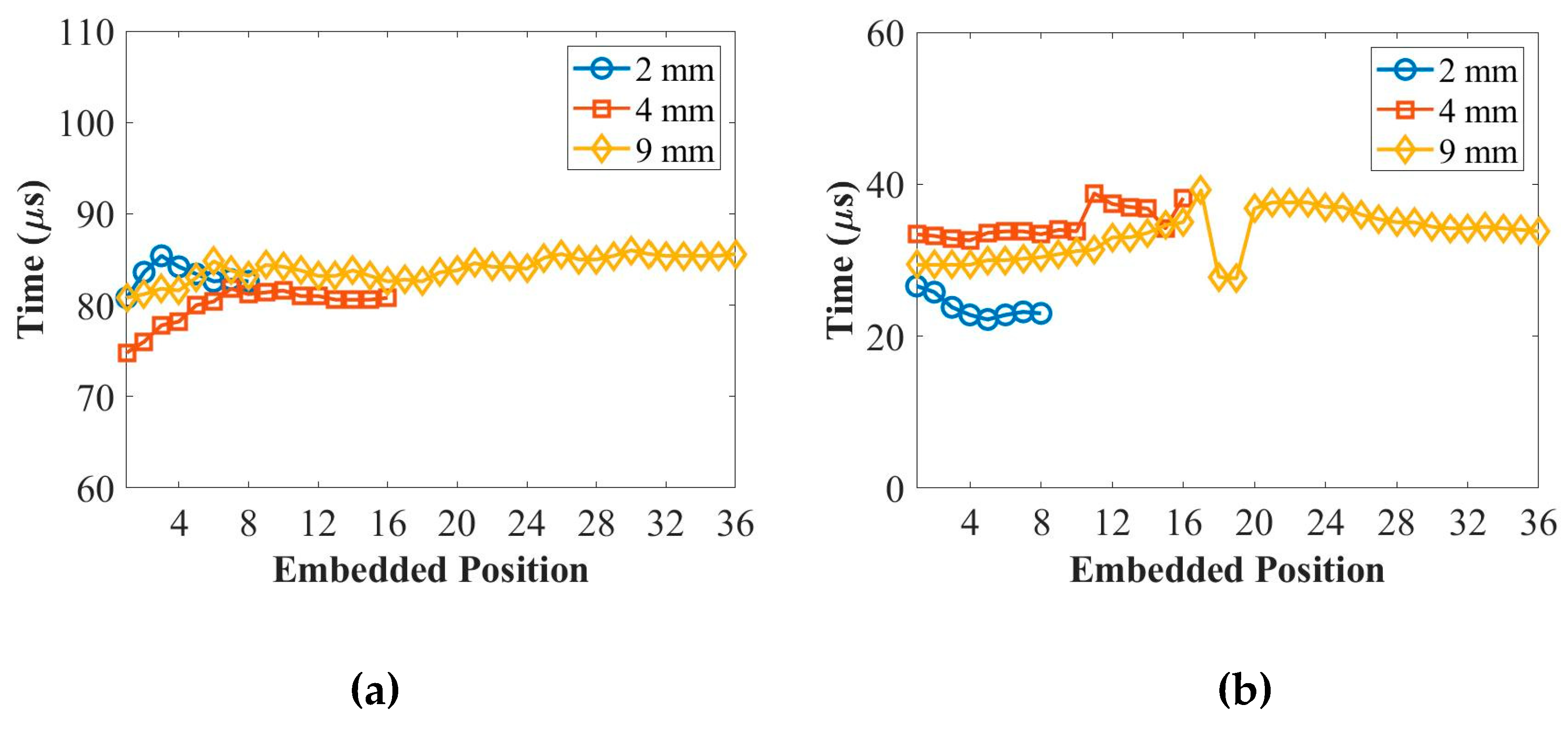
Figure 3 displays the relationship between the time-of-flight (ToF) and different placing positions for the thicknesses of 2 mm, 4 mm, and 9 mm panels at 50 kHz and 250 kHz. In the context of the composite stacking sequences during modeling, position 0 on the x-axis in
Figure 3 corresponds to the scenario where the PZT transducers are surface-mounted on top of the composite panel. Moving along the x-axis from position 1 to the end position (e.g., from the 1st to 8th layer for the 2 mm panel in
Figure 3) represents the embedding of PZT transducers from the 1st layer to the middle layer of the composite panel.
Observing
Figure 3, it can be seen that the ToF values appear random or show no clear trend with the increase in placing positions of the PZT transducers. This indicates that the placing positions of the PZT transducers have no significant effect on the ToF of the ultrasonic guided waves. Based on these findings, it can be concluded that the placement of the PZT transducers in different layers of the composite panels does not significantly impact the time it takes for the ultrasonic guided waves to propagate through the material, as indicated by the ToF results.
2.2.3. Peak Amplitude
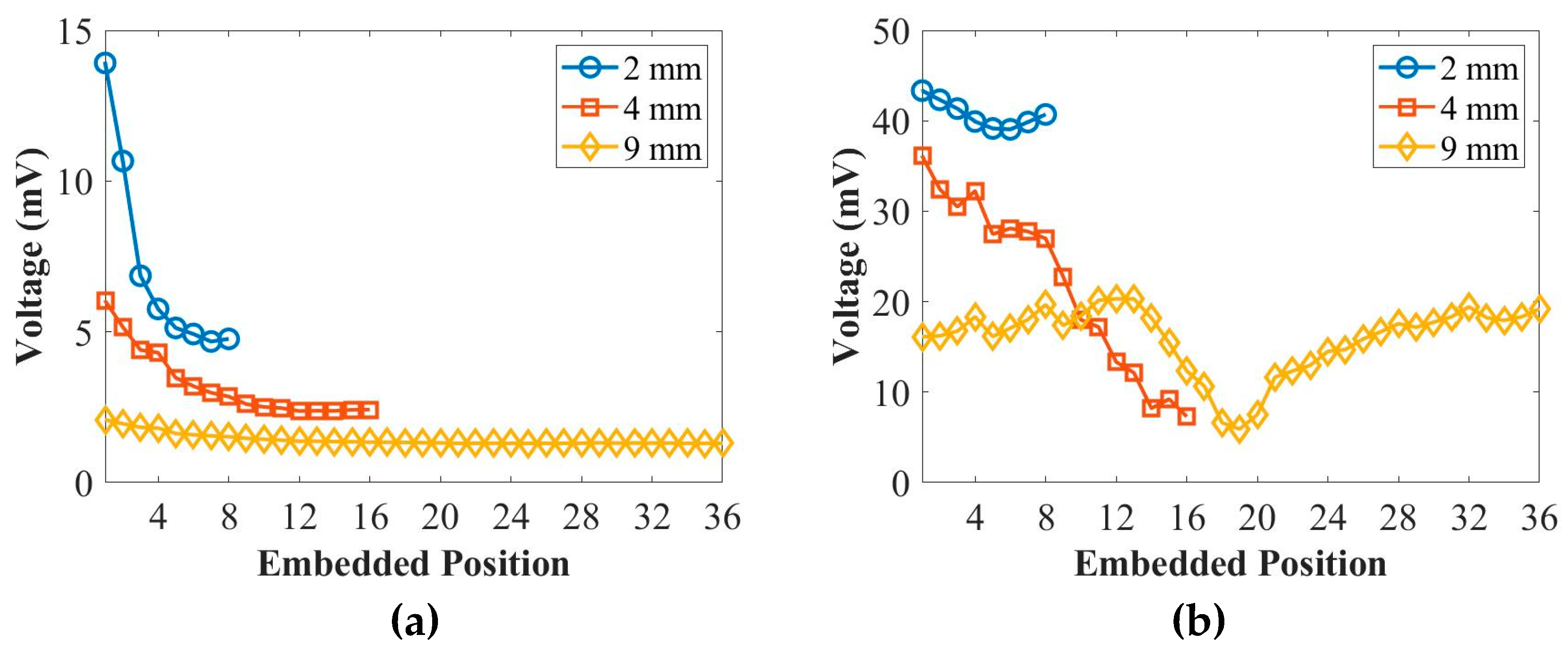
Figure 4 illustrates the relationship between the peak amplitude of the first wave packet and different placing positions for the thicknesses of 2 mm, 4 mm, and 9 mm panels at 50 kHz and 250 kHz. According to
Figure 4, it is observed that the peak amplitude of the first wave packet decreases as the transducers are placed in a deeper position within the composite panels. This behaviour is observed for the thicknesses of 2 mm, 4 mm, and 9 mm panels at 50 kHz. However, for the S
0 mode at 250 kHz, there is no significant change in the peak amplitude of the first wave packet with respect to the placing positions. Therefore, based on the findings from
Figure 4, it can be stated that the peak amplitude of the first wave packet for the A
0 mode at 50 kHz reduces as the placing positions of the transducers are moved to deeper positions within the composite panels. On the other hand, the peak amplitude of the first wave packet for the S
0 mode at 250 kHz does not exhibit a significant variation with the changing placing positions.
3. Experimental Setup
The coupons consisted of unidirectional carbon fibre prepregs, specifically Hexply® IM7/8552, with stacking sequences of [(0°/+45°/-45°/+90°)n]s, where n represented the number of plies (2, 4, or 9) corresponding to the thicknesses of 2 mm, 4 mm, and 9 mm panels, respectively. The size of the composite coupon was 260 mm × 45 mm, and the distance between the two PZT transducers was set to 180 mm to avoid any overlap between crosstalk and the first wave packet of the embedded signals at 50 kHz. The distances from the centre of the PZT transducers to the edges were 40 mm in the x-direction and 22.5 mm in the y-direction. For embedding and surface-mounting, DuraActTM (P-876.K025) PZT transducers were used during the manufacturing process. The preparation of the diagnostic film, which connected to the PZT transducers using a Dimatix material printer (DMP-2580), and the embedding and surface-mounting techniques can be referred to in the author's previous work [
10].
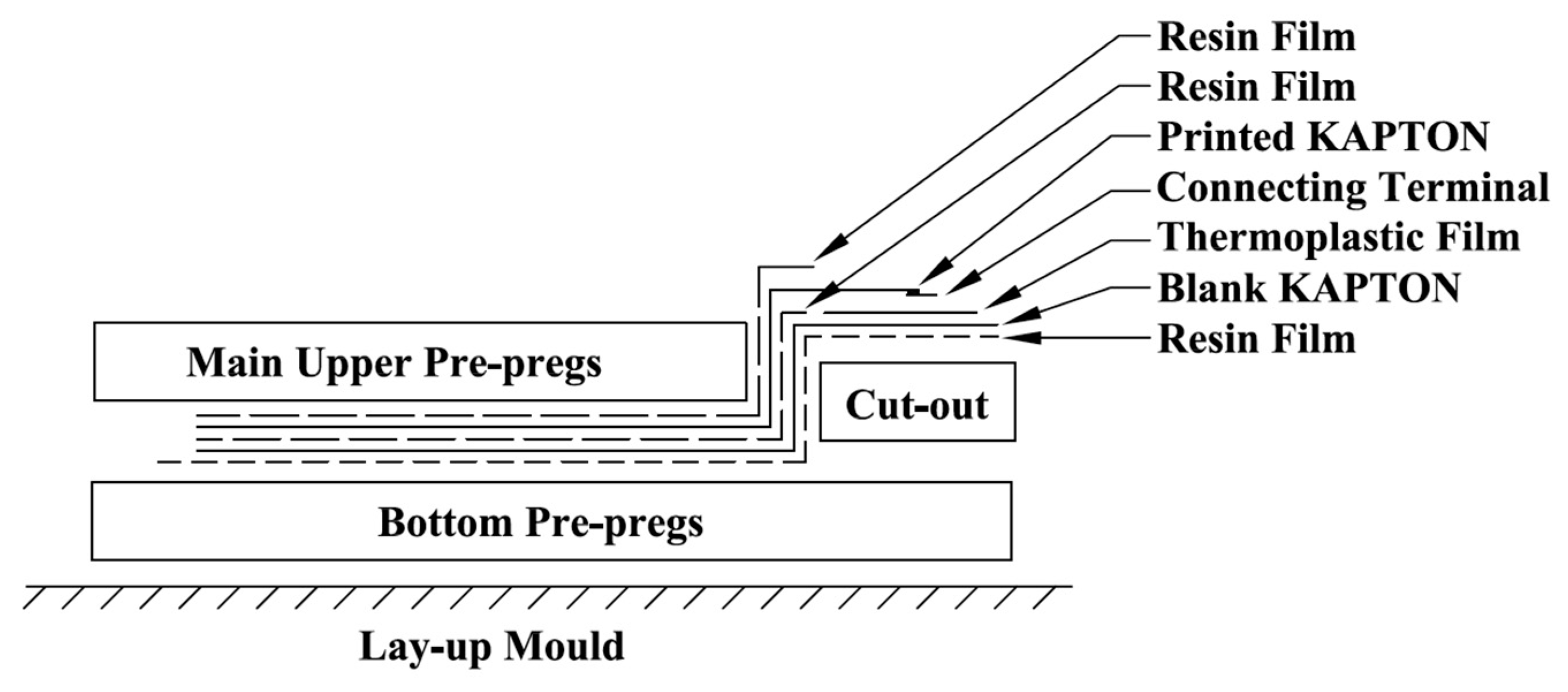
Figure 5 provides a schematic of a cut-out embedding technique that allowed for edge trimming after curing.
Figure 6 shows the schematic of the placing positions of the PZT transducers within the composite coupons.
Figure 7 displays examples of the lay-up for middle embedding, as well as a trimming coupon after curing, with middle-embedded ending terminals and connectors. Lastly,
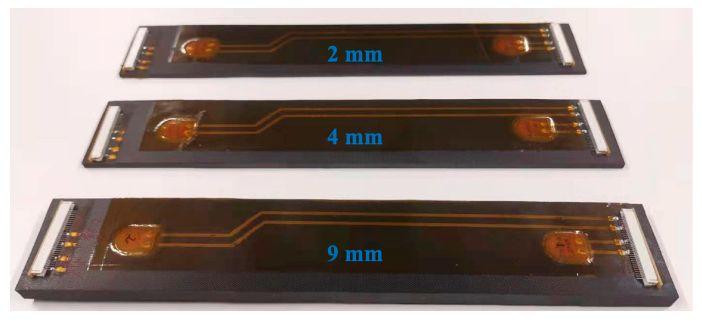
Figure 8 shows all three composite coupons with surface-mounted diagnostic films and PZT transducers, as well as the quarter-embedded ending terminals and connectors for the thicknesses of 2 mm, 4 mm, and 9 mm, respectively. These figures provide visual representations of the experimental setup, including the composite coupons with their respective embedded and surface-mounted PZT transducers, the diagnostic films, and the placing positions of the transducers within the coupons.
4. Results and Discussions
In this section, the amplitude of ultrasonic guided waves (UGW) based on active sensing will be investigated to compare the actuation behaviours using different placing positions of PZT transducers across the different thicknesses of composites.
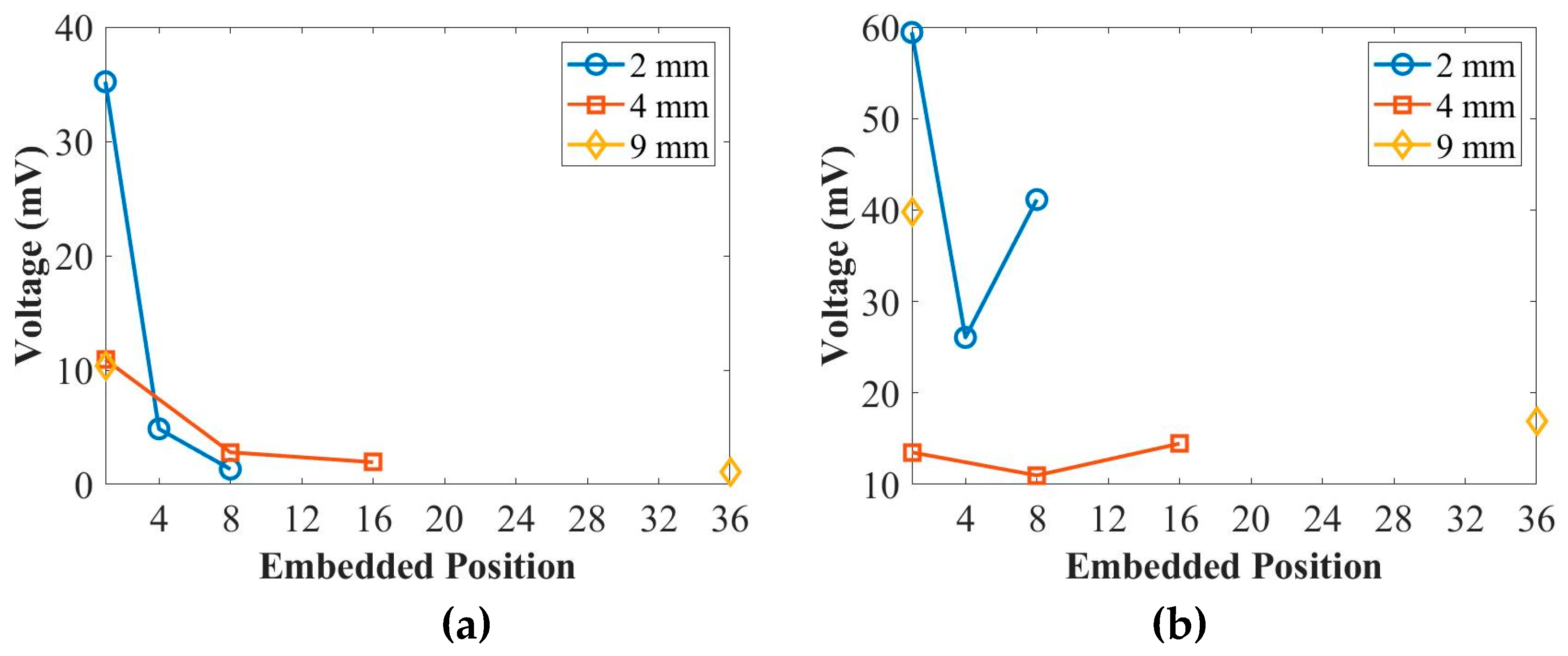
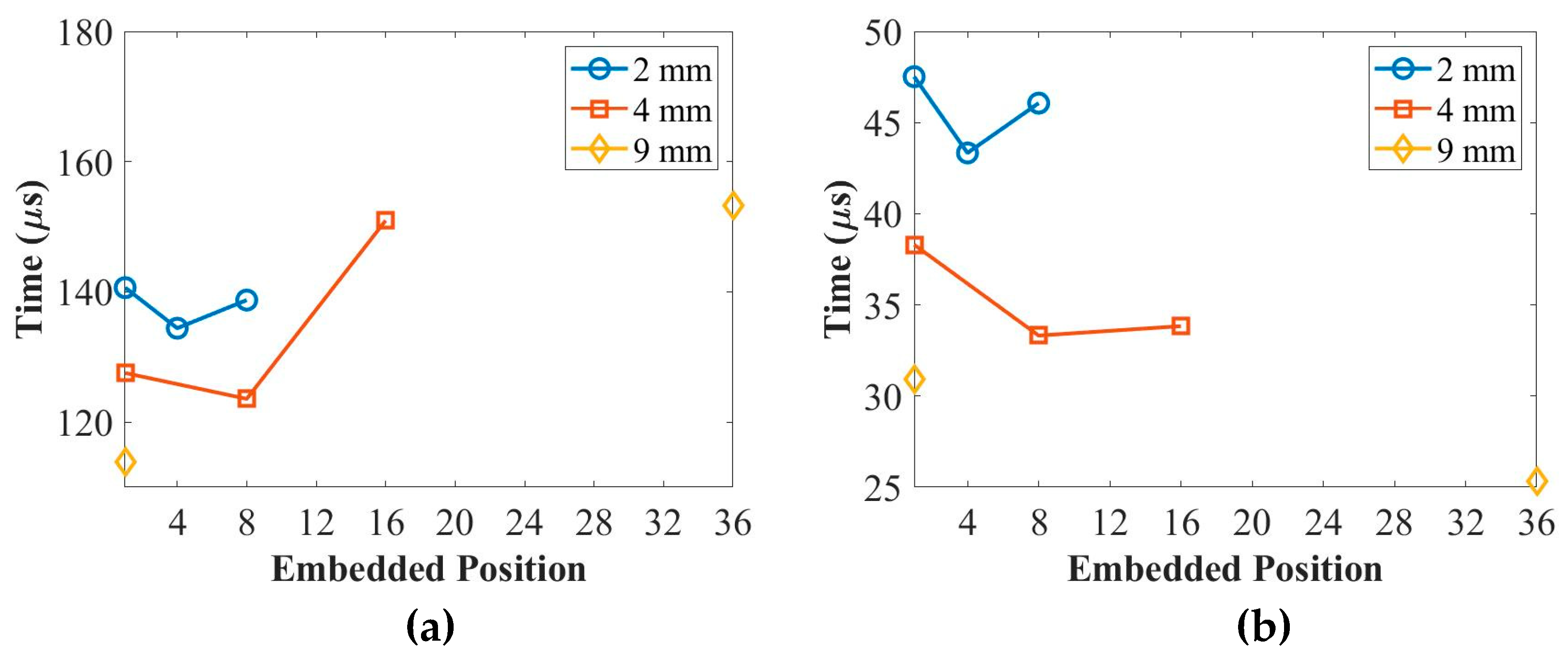
Figure 9 and
Figure 10 present the peak amplitude and time-of-flight (ToF) of the first wave packet of UGW actuated by PZT transducers in different placing positions for the 2 mm, 4 mm, and 9 mm thick coupons at 50 kHz and 250 kHz, respectively. In
Figure 9, it can be observed that the peak amplitude of the first wave packet for the surface-mounted signal is higher compared to the quarter- and middle-embedded signals at 50 kHz. However, the placing positions do not significantly affect the peak amplitude at 250 kHz.
Figure 10 demonstrates that the ToF of the UGW is not influenced by the placing positions of the PZT transducers at both 50 kHz and 250 kHz.
As it can be seen the experimental and numerical simulations results are in good agreement. These experimental results provide insights into the actuation behaviours of UGW using different placing positions of PZT transducers across various thicknesses of composites. The peak amplitude of the first wave packet is influenced by the placing positions at 50 kHz but remains unaffected at 250 kHz. Meanwhile, the ToF of the UGW is independent of the placing positions at both frequencies.
5. Conclusions
In this paper, the effect of ultrasonic guided waves (UGW) through different layers of composite plates was investigated using both numerical and experimental approaches.
The numerical analysis involved finite-element modeling to simulate the UGW actuated by PZT transducers placed at different positions, ranging from the surface to the middle layers of the composite plates. The time-of-flight (ToF) and peak amplitude of the first wave packet of UGW through different layers were studied. The numerical results revealed that the ToF did not exhibit significant changes at 250 kHz. However, at 50 kHz, the peak amplitude of the first wave packet decreased with deeper embedding positions for the 2 mm, 4 mm, and 9 mm composite plates. This suggests that the depth of the embedding position has an influence on the peak amplitude of the UGW, particularly at lower frequencies.
The experimental studies involved the fabrication of composite coupons with different thicknesses (2 mm, 4 mm, and 9 mm). PZT transducers were mounted on the surface and embedded in the quarter and middle positions of each composite coupon. UGW actuated by PZT transducers in different placing positions were compared. It was observed that at 50 kHz, the peak amplitude of the first wave packet for the surface-mounted signal was higher than that of the quarter- and middle-embedded signals. This indicates that the A0 mode, which dominates at 50 kHz, is affected by the placing positions of the PZT transducers. These experimental results were found to be in agreement with the numerical simulation results.
In summary, both the numerical and experimental investigations provided insights into the behaviour of UGW through different layers of composite plates. The results demonstrated that the peak amplitude of the UGW is influenced by the depth of embedding position and the A0 mode is particularly sensitive to the placing positions of the PZT transducers.
Acknowledgments
The first author wishes to acknowledge the funding from the Aviation Industry Corporation of China, Ltd. (AVIC), AVIC General Huanan Aircraft Industry Co., Ltd. and the China Scholarship Council (No. [2017] 5082).
References
- Giurgiutiu, V. Structural Health Monitoring with Piezoelectric Wafer Active Sensors; Academic Press, 2014. [Google Scholar]
- Yuan, F.-G. Structural health monitoring (SHM) in aerospace structures; Woodhead Publishing, 2016. [Google Scholar]
- Dafydd, I.; Sharif Khodaei, Z. Analysis of barely visible impact damage severity with ultrasonic guided Lamb waves. Structural Health Monitoring 2020, 19, 1104–1122. [Google Scholar] [CrossRef]
- Zou, F.; Aliabadi, M. On modelling three-dimensional piezoelectric smart structures with boundary spectral element method. Smart Materials and Structures 2017, 26, 055015. [Google Scholar] [CrossRef]
- Si, L.; Li, Z. Online structural state assessment for aerospace composite structures using an acousto-ultrasonics-based multi-damage index identification approach. Structural Health Monitoring 2020, 19, 1790–1807. [Google Scholar] [CrossRef]
- El Mountassir, M.; Yaacoubi, S.; Mourot, G.; Maquin, D. An adaptive PCA-based method for more reliable ultrasonic guided waves SHM: Data-driven modeling and experimental validation in high attenuating medium. Structural Control and Health Monitoring 2021, 28, e2634. [Google Scholar] [CrossRef]
- Yue, N.; Aliabadi, M. A scalable data-driven approach to temperature baseline reconstruction for guided wave structural health monitoring of anisotropic carbon-fibre-reinforced polymer structures. Structural Health Monitoring 2020, 19, 1487–1506. [Google Scholar] [CrossRef]
- Haq, M.; Naqvi, T. Numerical assessment of induced damages of RC frames using PZT patch in embedded configurations with and without bond layer. Materials Today: Proceedings 2021, 43, 1977–1982. [Google Scholar] [CrossRef]
- De Luca, A.; Caputo, F.; Khodaei, Z.S.; Aliabadi, M. Damage characterization of composite plates under low velocity impact using ultrasonic guided waves. Composites Part B: Engineering 2018, 138, 168–180. [Google Scholar] [CrossRef]
- Feng, T.; Bekas, D.; Aliabadi, M. Active Health Monitoring of Thick Composite Structures by Embedded and Surface-Mounted Piezo Diagnostic Layer. Sensors 2020, 20, 3410. [Google Scholar] [CrossRef] [PubMed]
- Dziendzikowski, M.; Kurnyta, A.; Dragan, K.; Klysz, S.; Leski, A. In situ Barely Visible Impact Damage detection and localization for composite structures using surface mounted and embedded PZT transducers: A comparative study. Mechanical Systems and Signal Processing 2016, 78, 91–106. [Google Scholar] [CrossRef]
- Lampani, L.; Sarasini, F.; Tirillò, J.; Gaudenzi, P. Analysis of damage in composite laminates with embedded piezoelectric patches subjected to bending action. Composite Structures 2018, 202, 935–942. [Google Scholar] [CrossRef]
- Kahandawa, G.C.; Epaarachchi, J.; Wang, H.; Lau, K. Use of FBG sensors for SHM in aerospace structures. Photonic Sensors 2012, 2, 203–214. [Google Scholar] [CrossRef]
- Yang, B.; Xuan, F.Z.; Jin, P.; Hu, C.; Xiao, B.; Li, D.; Xiang, Y.; Lei, H. Damage Localization in Composite Laminates by Building in PZT Wafer Transducers: A Comparative Study with Surface-Bonded PZT Strategy. Advanced Engineering Materials 2019, 21, 1801040. [Google Scholar] [CrossRef]
- Mall, S.; Hsu, T. Electromechanical fatigue behavior of graphite/epoxy laminate embedded with piezoelectric actuator. Smart Materials and Structures 2000, 9, 78. [Google Scholar] [CrossRef]
- Yocum, M.; Abramovich, H.; Grunwald, A.; Mall, S. Fully reversed electromechanical fatigue behavior of composite laminate with embedded piezoelectric actuator/sensor. Smart materials and structures 2003, 12, 556. [Google Scholar] [CrossRef]
- Su, Z.; Wang, X.; Chen, Z.; Ye, L.; Wang, D. A built-in active sensor network for health monitoring of composite structures. Smart Materials and Structures 2006, 15, 1939. [Google Scholar] [CrossRef]
- Giurgiutiu, V. Academic PressStructural health monitoring of aerospace composites; 2015. [Google Scholar]
- Feng, T.; Aliabadi, M.H.F. Structural Integrity Assessment of Composites Plates with Embedded PZT Transducers for Structural Health Monitoring. Materials 2021, 14, 6148. [Google Scholar] [CrossRef] [PubMed]
- Feng, T.; Aliabadi, M.H.F. Smart Patch for Structural Health Monitoring of Composite Repair. Applied Sciences 2022, 12, 4916. [Google Scholar] [CrossRef]
- Feng, T.; Sharif Khodaei, Z.; Aliabadi, M.H.F. Influence of Composite Thickness on Ultrasonic Guided Wave Propagation for Damage Detection. Sensors 2022, 22, 7799. [Google Scholar] [CrossRef] [PubMed]
- Cenek, S.; Mudit, R.; Radek, H. Structural health monitoring of composite structures using embedded pzt sensors in space application. In Proceedings of the PHM Society European Conference.
- Her, S.-C.; Chen, H.-Y. Deformation of Composite Laminates Induced by Surface Bonded and Embedded Piezoelectric Actuators. Materials 2020, 13, 3201. [Google Scholar] [CrossRef] [PubMed]
- Lammering, R.; Gabbert, U.; Sinapius, M.; Schuster, T.; Wierach, P. Lamb-wave based structural health monitoring in polymer composites; Springer, 2017. [Google Scholar]
- Systems, D. ABAQUS/CAE user’s guide. Dassault Systemes Simulia. Providence, RI: 2014.
- Su, Z.; Ye, L. Identification of damage using Lamb waves: From fundamentals to applications; Springer Science & Business Media, 2009; Volume 48. [Google Scholar]
- Yue, N.; Aliabadi, M. A scalable data-driven approach to temperature baseline reconstruction for guided wave structural health monitoring of anisotropic carbon-fibre-reinforced polymer structures. Structural Health Monitoring 2019, 1475921719887109. [Google Scholar] [CrossRef]
|
Disclaimer/Publisher’s Note: The statements, opinions and data contained in all publications are solely those of the individual author(s) and contributor(s) and not of MDPI and/or the editor(s). MDPI and/or the editor(s) disclaim responsibility for any injury to people or property resulting from any ideas, methods, instructions or products referred to in the content. |
© 2023 by the authors. Licensee MDPI, Basel, Switzerland. This article is an open access article distributed under the terms and conditions of the Creative Commons Attribution (CC BY) license (http://creativecommons.org/licenses/by/4.0/).
