Preprint
Article

Numerical Simulation and Field Test of PDC Bit with Mixed Cutter Arrangement to Break Non-Homogeneous Granite

Altmetrics

Downloads

94

Views

22

Comments

0

A peer-reviewed article of this preprint also exists.

This version is not peer-reviewed

Submitted:

21 July 2023

Posted:

25 July 2023

You are already at the latest version

Alerts
Abstract
The cutter structure and layout scheme of PDC (Polycrystalline Diamond Compact) bits are important factors in improving efficiency. To further improve the drilling efficiency of PDC bits, axe, triangular prism, and cylindrical PDC cutters were used as research objects. Based on the measured granite data, a finite element model of non-homogeneous granite was established and verified by uniaxial compression simulation. The rock-breaking process of different cutter combination schemes was compared using the finite element method, and the parameters in the best scheme were optimized using the Box-Behnken response surface method. The results show that the constructed model of non-homogeneous granite is consistent with the stress-strain relationship of real granite and is reliable. The axe PDC cutter is more aggressive than the other two cutters and is more suitable for the front row of the bit blade tooth arrangement, while the triangular prism cutter is the second most aggressive and is suitable for the rear row of tooth arrangement, and the best combination scheme is the front row of axe cutter and the rear row of triangular prism cutter arranged alternately with the axe cutter. The optimal transverse and longitudinal distances of the optimized triangular prism cutter from the front axe cutter are 10mm and 7mm, and the optimal transverse and longitudinal distances of the rear axe cutter from the front cutter are 10.06mm and 7mm. The drilling speed is more stable during drilling and the PDC bit with mixed tooth arrangement has 16.8% and 16.6% higher rate of penetration(ROP) compared with the bit with single axe cutter and triangular prism cutter, and the drilling speed is more stable during working, which can effectively improve the rock breaking efficiency of the PDC bit. The field application proves that the bit with mixed cutter arrangement is easier to break the complex formations, with more stable ROP and better efficiency. The study can provide theoretical support for the cutter layout of the PDC bit.
Keywords: 
Subject: Engineering  -   Mechanical Engineering

1. Introduction

China's domestic shallow oil and gas resources have been exploited, and the development of unconventional oil and gas resources will be the future focus. According to a survey and study, China ranks second in the world in terms of unconventional oil and gas resources reserves, but the external dependence on oil and natural gas is as high as 73% and 43% respectively, and it is urgent to increase the exploitation of unconventional oil and gas resources [1]. However, unconventional oil and gas resources are located in complex formations and are difficult to extract [2], which puts higher requirements on the performance of drill bits. It is well known that PDC (Polycrystalline Diamond Compact) bits have higher wear resistance and efficiency compared with roller cone bits, especially in hard formations [3,4], which has led to a higher market share of PDC bits, which was investigated to be as high as 75%-80% in 2018 [5,6]. However, the current common PDC bits mainly rely on the mounted cutters to break the rock by shearing, which is weak in aggressiveness, and it is difficult to penetrate hard rocks (such as granite) during drilling, and the PDC cutter needs to constantly rub against the rock and wait for the drill string to accumulate enough energy to break the rock, which leads to a serious decrease in bit life and efficiency and increases the drilling cost, so the performance of PDC bits needs to be improved, and the structure of PDC cutter is closely related to the performance of the bit.
The study or optimization of the performance of PDC cutters with different structures is an effective way to improve the overall drill bit life and efficiency [7]. Therefore, many scholars have conducted a lot of research on the rock-breaking characteristics of PDC cutters under different structures and their formation suitability, especially for non-planar cutters [8]. Dong et al [9] conducted a study on the rock-breaking characteristics and efficiency of circular cutters, axe-shaped cutters, angled cutters, wedge-shaped cutters, and triangular prism cutters through experiments combined with numerical simulation methods. Their results showed that the axe cutters have better drilling ability in hard formations and are suitable for the front row of the cutter blade of the PDC bit, while the angled cutters are more suitable for auxiliary rock breaking and should be installed in the back row of the cutter blade of the PDC bit. Conical PDC cutters are mostly used for auxiliary rock breaking in PDC bits [10,11]. Li et al [12] used the finite element method to numerically simulate the rock-breaking process of conventional PDC cutters, conical PDC cutters, and the overall rock-breaking process of the drill bit, and the results of the study showed that the conical cutters as auxiliary cutting structures could well produce pre-breaking of rocks at 100 MPa compressive strength, thus improving the overall drilling ability of the bit in hard rocks, while this approach was not effective for rocks with 50 MPa compressive strength. The axe PDC cutter not only has the characteristics of conventional cutter’s shear breaking in the rock-breaking process but also has a crushing effect on the rock, which can significantly improve the ROP and mechanical specific energy (MSE) of the drill bit [13,14]. The unique ridged structure of the axe-shaped PDC cutter not only reduces the weight of the bit but also maximizes the rock-breaking efficiency. It has been studied that a drill bit with an axe cutter can provide up to 35% higher instantaneous ROP for the same input energy [15].
Because the axe-shaped PDC cutter has a high ROP during rock breaking, it is easier to penetrate hard rock, which can prevent the bit from sticking and sliding [16], keep the weight on the bit (WOB) stable during drilling, and keep the bit drilling at high ROP, and its simple structure, easy processing, and relatively mature technology make it a preferable choice for drilling into hard rock.
In addition to axe-shaped cutters, new cutter structures have been proposed by some scholars and verified by experiments or numerical simulations. For example, Wang et al [17] designed a wavy PDC cutter using the mole paw toe as a bionic prototype, and it was found by field experiments that the life and efficiency of PDC bits could be improved by 54% and 230%, respectively, using this cutter, which provided new ideas and methods for the performance improvement of PDC bits. Zeng et al [18] designed a triangular non-planar PDC cutter, numerically simulated its rock-breaking process, and compared it with conventional PDC cutters, and found that the designed cutter was subject to less rock-breaking resistance, easier to break the rock, and had both good wear resistance and efficiency. Liu et al [19] studied the rock-breaking characteristics of the triangular PDC cutter by numerical simulation and found that this cutter not only has a shearing effect on the rock, but also has a crushing effect, and the results of field experiments showed that the PDC bit using this cutter requires less torque and penetrates the rock more easily, which helps the stable drilling of the bit. The change or optimization of the cutter structure is a more intuitive way to improve the performance of the bit. In addition, the reasonable arrangement of the cutter position on the PDC bit blade can also improve the performance of the drill bit to a great extent.
To rationalize the cutter layout, Chen et al [20] changed the cutter layout by extracting the characteristic curve of the Siberian sheep's horn, which will be applied to the design of the cutter blade of the PDC drill bit, and after the study, the probability of load concentration of the changed cutter was greatly reduced and the utilization rate of the cutter was increased to 90%, and this study helped to improve the overall life and efficiency of the PDC drill bit. Previous PDC cutters were often arranged in one row on the cutter blade [21], which would lead to wasted space on the cutter blade, and gradually, the cutter layout of some drill bits began to be changed to two or even more rows on one cutter blade [22], which not only rationalized the use of space on the cutter blade but also improved the efficiency and lifetime of PDC drill bits. Even if the cutter structure is not changed, changing the cutter space layout can greatly improve the performance of the whole drill bit[12], and these studies mentioned above provide theoretical support for the cutter space layout.
A rational approach is important in the study of the rock-breaking process of PDC bits. Most of the current related studies, using experiments combined with numerical simulations [23], have greatly improved the accuracy of the simulations while reducing the research cost. However, most of the studies treat the rock as a homogeneous model during the numerical simulation, which does not reflect the real scenario of the actual drilling process. In addition, the current studies on PDC cutting tool-related parameters, such as back rake angle [24], depth of cut [25], and speed [26], are conducted in an interval-modified parameter study, which yields experimental results that do not necessarily reflect the true relationship between the parameters and the target variables, and thus may lead to inaccurate conclusions.
Box-Behnken is a method for constructing multi-factor orthogonal rotating combination experiments [27], which considers the random error in the experimental process and allows for continuous analysis of each level in the process of finding the optimal test conditions, while the method can fit unknown complex functional relationships with simple primary or quadratic polynomials in a small area, which is computationally simple and can solve practical problems. The above method simplifies the optimization process, and at the same time can obtain more reliable results [28], which provides ideas and ways to solve optimization problems in engineering.
It is not difficult to find that although the performance of axe cutters and triangular prism cutters has been fully verified, most of the relevant research is focused on the rock-breaking characteristics of single cutters, and there are still gaps in the research related to the mixed cutter laying of both, and there is still a very large research space about the parameters, effects and rock-breaking characteristics of mixed cutter arrangement, and the numerical simulation process does not reflect the real formation is also a problem of the current research. Given this, this paper constructs a non-homogeneous granite model using Python script in ABAQUS software based on the measured granite data in the field and investigates the rock-breaking process of the mixed tooth arrangement scheme of the axe, triangular prism, and cylindrical PDC cutters using the finite element method, and after determining the best scheme, the cutters arrangement spacing is optimized using the Box-Behnken response surface method, based on the obtained parameters, a hybrid cutter arrangement PDC bit was constructed and compared with one type cutter arrangement bit for rock breaking numerical simulation. The study is of guiding significance for the rational layout of cutters to improve the performance of PDC bits.

2. Modeling and Validation of Non-Homogeneous Granites

2.1. Modeling of Non-Homogeneous Granites

As shown in Figure 1, microscopic observations were made by examining the actual granite samples. As can be seen from the figure, the actual granite is not homogeneous and contains many different mineral crystals. All of these crystal structures have distinctive dimensional and mechanical characteristics and vary widely and differently [29].
To reflect the condition of the granite formation during actual drilling, the material properties of each component crystal in the granite, based on the actual measurements obtained in the literature [30,31,32], are shown in Table 1.
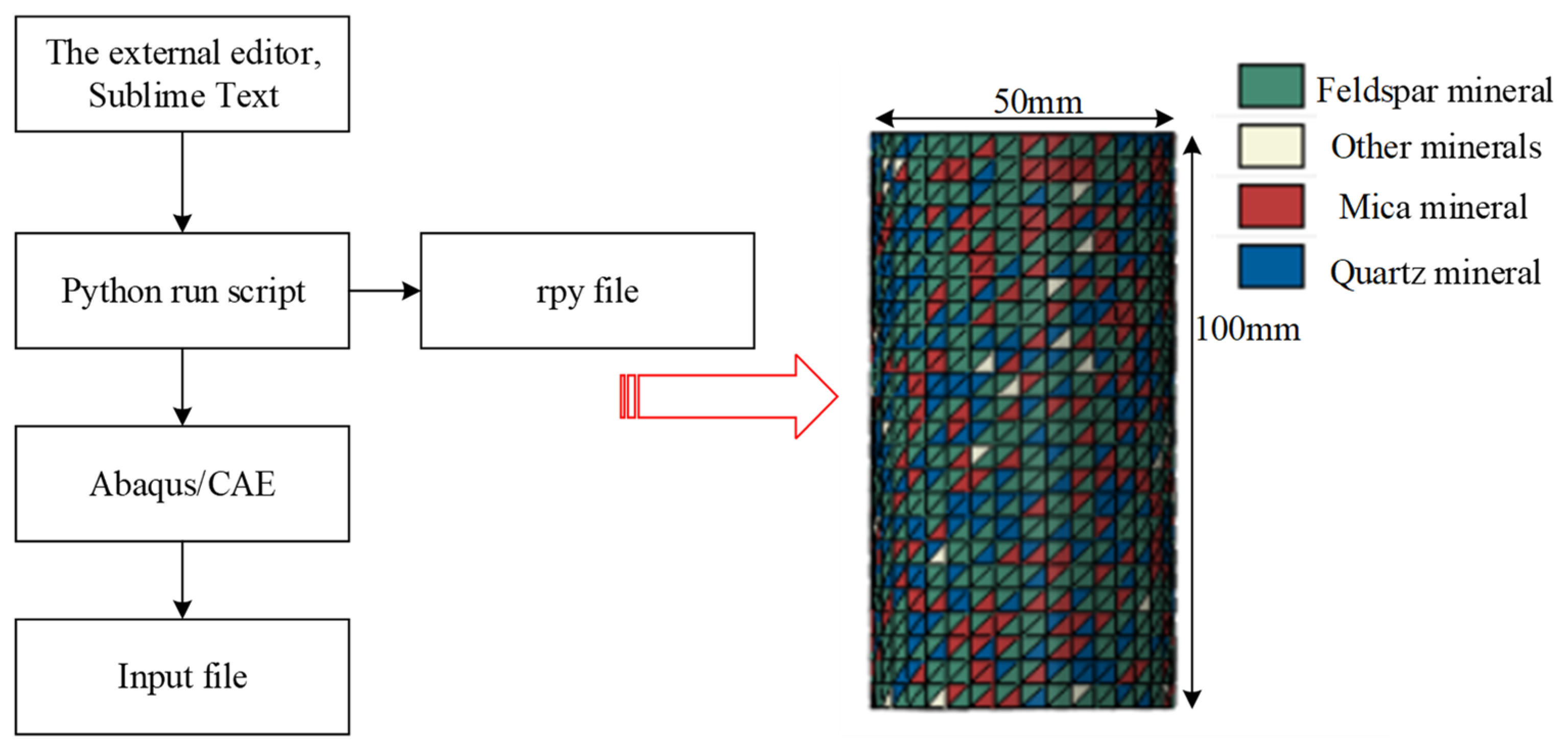
Using the parameters in Table 1 above, the external compiler Sublime Text was used to write Python scripts, and the corresponding Python scripts were saved in rpy file format and then imported into the ABAQUS CAE module to first generate the material parameters of each part of the minerals, and then the minerals were formed into their respective sets, and the sets and materials were correlated with the finite element mesh model by generating random numbers to finally obtain the rock model as shown in Figure 2.

2.2. Granite Model Validation

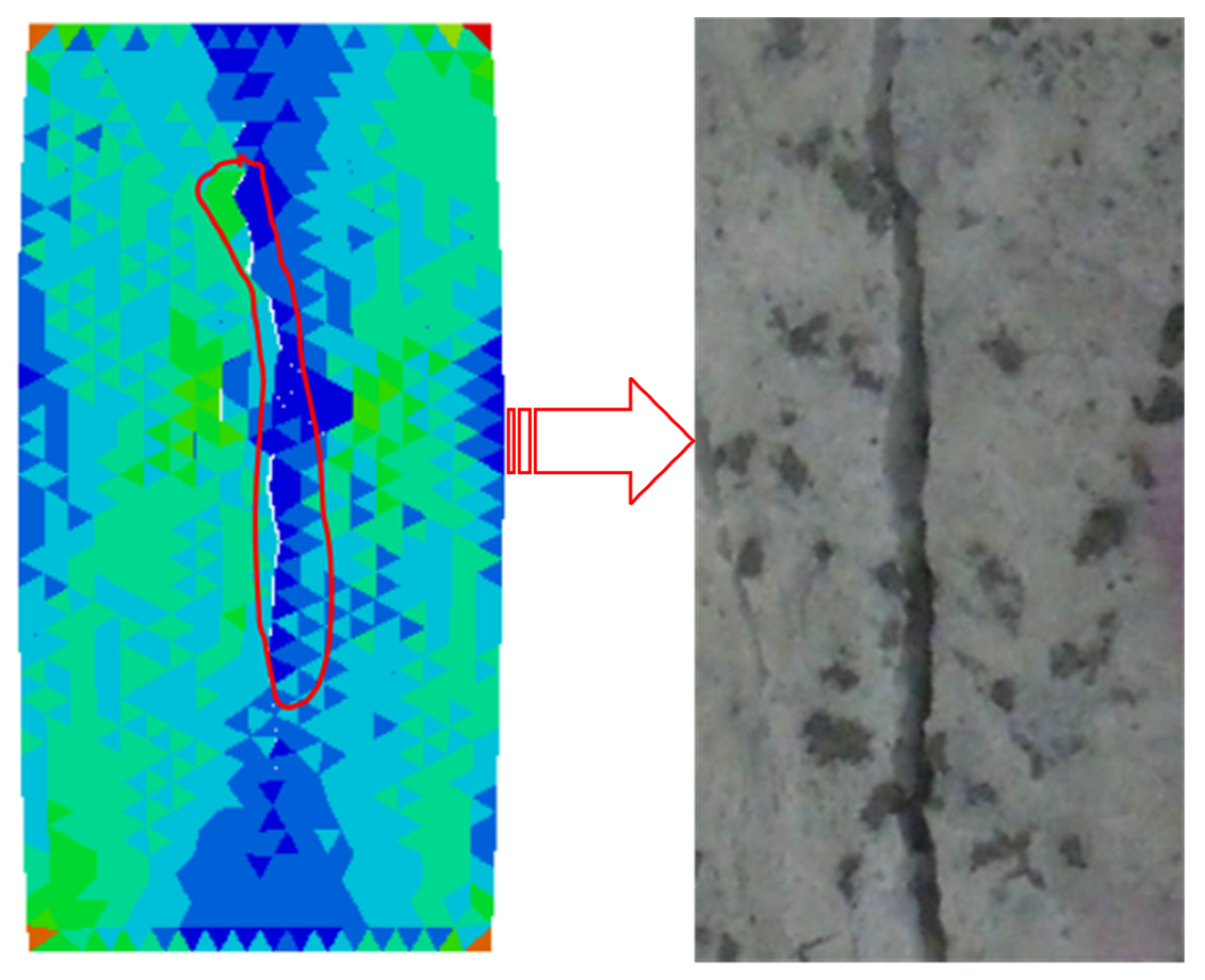
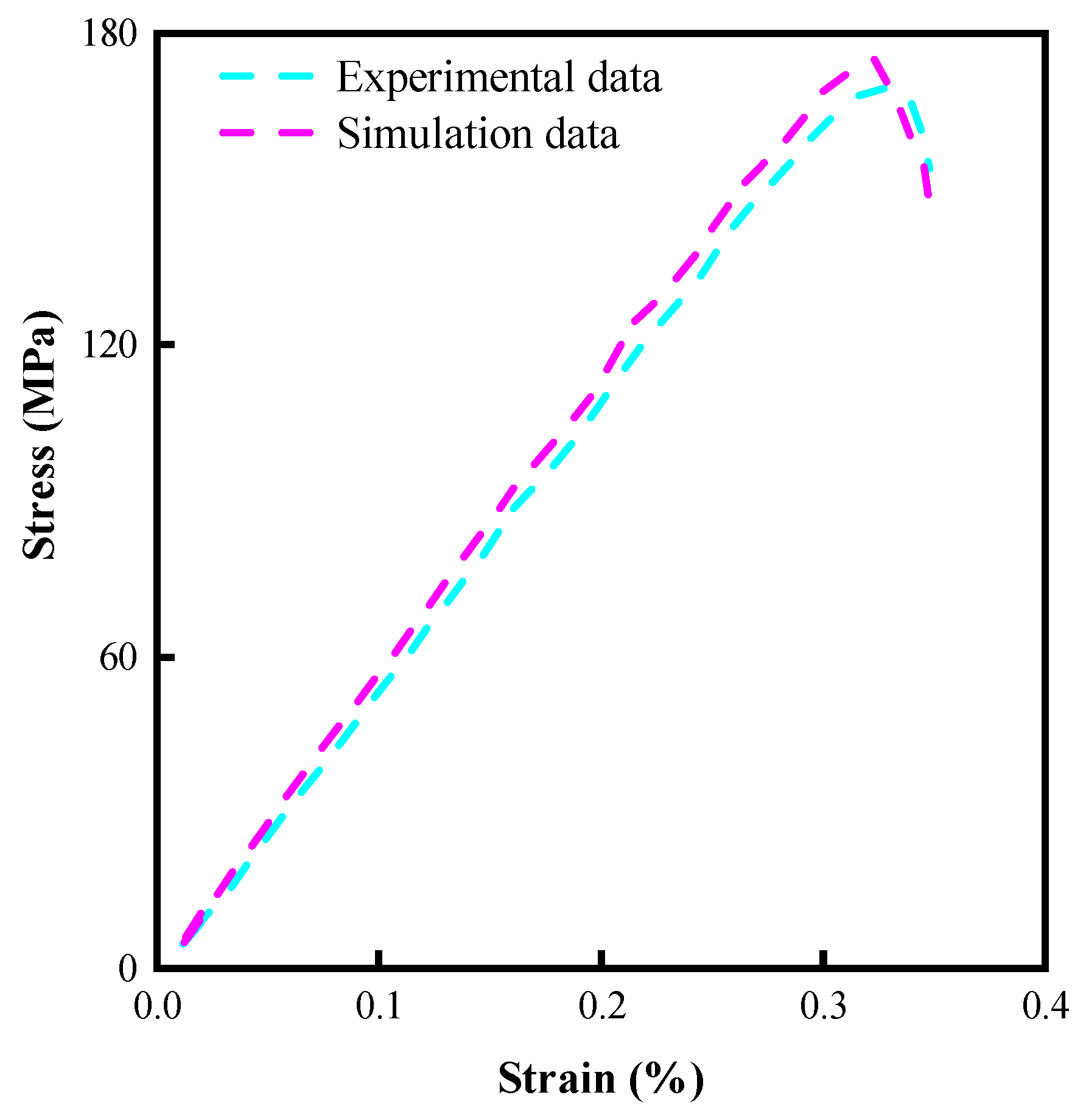
To ensure the accuracy of the numerical simulation, uniaxial compression numerical simulation tests were performed on the established inhomogeneous granite model, during the simulation, the lower end of the rock model was fixed and a downward velocity of 0.001 mm/s was applied to the upper end, and the results of the comparison between the simulation and experimental results [31] are shown in Figure 3, and the obtained rock stress-strain data were compared with the experimental results in the literature [33], as shown in Figure 4.
As can be seen from Figure 3 and Figure 4, the crack and stress-strain curves after uniaxial compression are consistent with the experiments, which verifies the accuracy of the constructed model of non-homogeneous granite. Rock models are very important for the numerical simulation of rock breaking, and the most commonly used ones are the M-C (Mohr-Coulomb) and D-P (Drucker-Prager) models, respectively, where the D-P model takes into account the hydrostatic pressure on the rock and can better explain the yielding phenomenon of the rock, so the D-P model is used in the study [34], and its mathematical equation is:
ρ I 1 + J 2 K = 0
I 1 = σ 1 + σ 2 + σ 3
J 2 = 1 6 σ 1 σ 2 2 + σ 2 σ 3 2 + σ 3 σ 1 2
ρ = 2 sin α 3 3 sin α
K = 6 e cos α 3 3 sin α
where ρ and K are experimental constants related only to the rock friction angle α and cohesion e.
PDC cutters break the rock mainly in shear, and the damage starts when the plastic stress of the rock exceeds its critical value. Neglecting the effect of the broken unit on the broken rock, the plastic strain criterion of the rock is:
ε r ε r l f
where εr is the equivalent plastic strain of the rock and εrlf is the equivalent plastic strain of the rock when damage occurs. I1 is the amount of stress in the first invariant and J2 is the stress bias in the second invariant.σ1σ2σ3 are the first, second, and third principal stresses, respectively.

3. Construction of the Model

3.1. Simplification and Creation of 3D Models

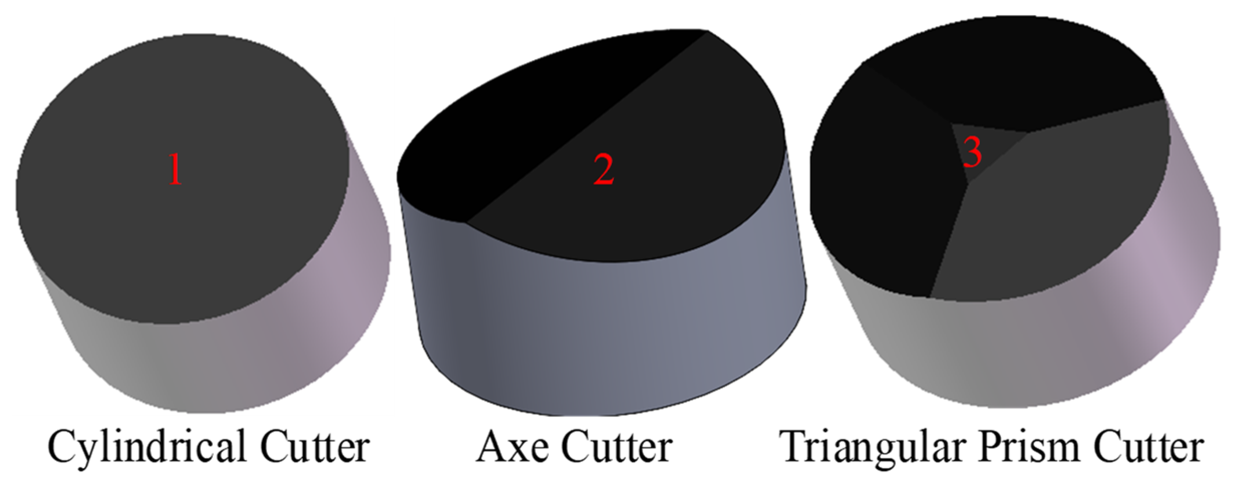
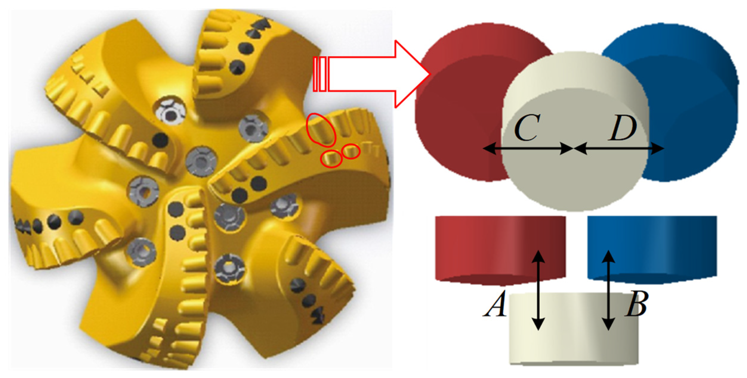
To study the effect of a double-blade hybrid cutter arrangement of PDC drill bit, cylindrical, axe, and triangular prism PDC cutters with a diameter of 13 mm and a height of 8 mm were constructed using SOLIDWORKS2021 software and numbered as shown in Figure 5, with cylindrical cutter number 1, axe cutter 2, and triangular prism cutter 3. The cutter parameters can be found in the literature [14,18]. The model of the PDC drill bit with double-blade tooth arrangement was simplified, and only some of the cutters in the front and back rows were retained for the subsequent study of the cutter layout scheme as well as the parameters, and the model changes before and after the simplification are shown in Figure 6, where A and B are the longitudinal distance of the back row of cutters from the front row of cutters with a value of 10 mm, C and D is the transverse distance of the back row of cutters from the front row of cutters with a value of 8 mm.

3.2. Finite Element Model Assumptions and Evaluation Guidelines

PDC cutter rock breaking is a very complex nonlinear process, and the study of this model focuses on the rock-breaking effect of the cutter under different schemes and parameter combinations. To improve the computational efficiency, it is necessary to omit secondary factors and make the following assumptions [16,23]:(1) Due to the difference in hardness between the PDC cutter and the rock material, the wear of the cutter during rock breaking is ignored and considered as a rigid body. (2) The rock is removed immediately upon breaking, and repeated cutting is not considered. (3) The rotational motion of the cutter at the bottom of the well is considered a linear motion.
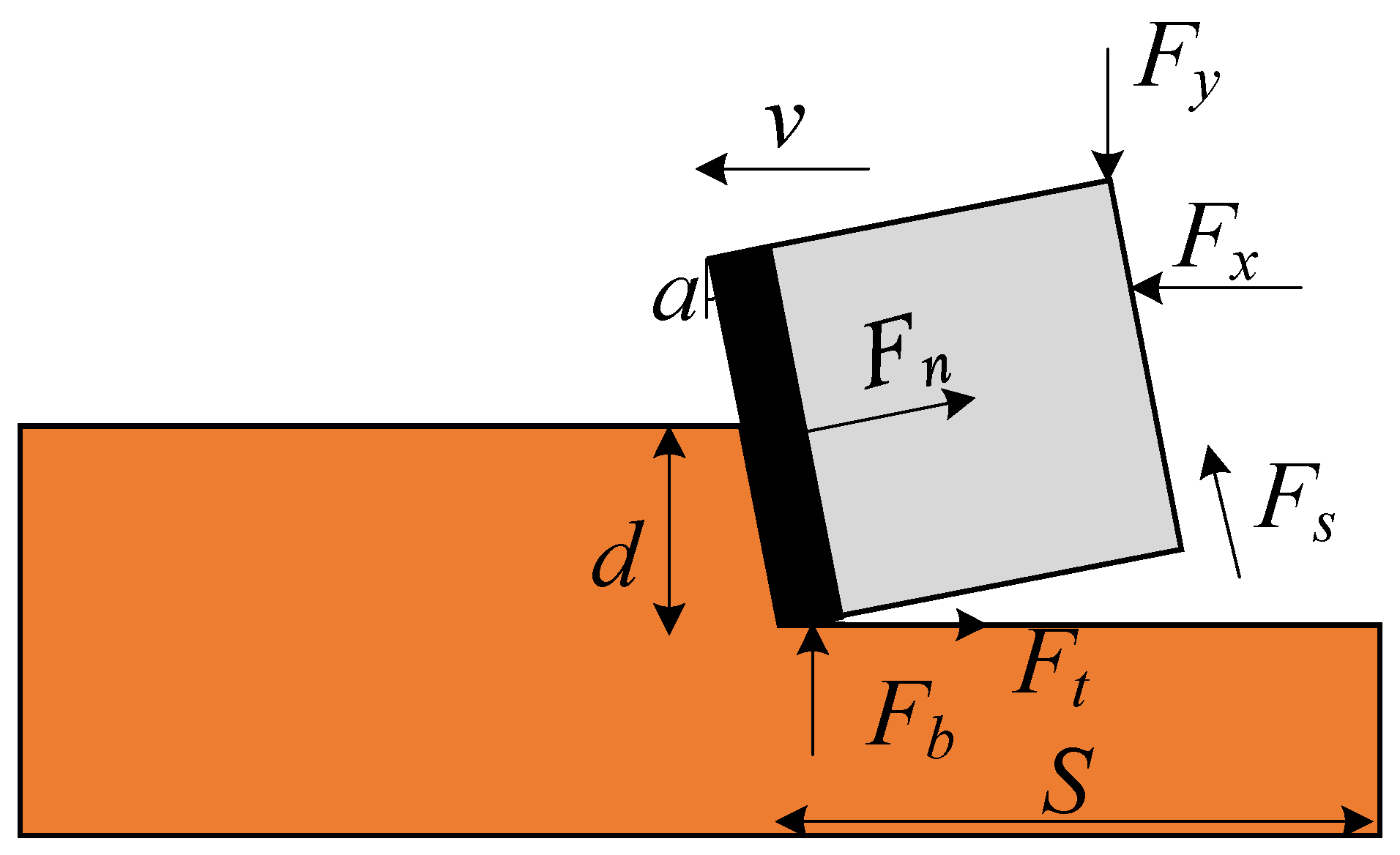
The interaction between the PDC cutter and the rock in the process of rock breaking can be represented in Figure 7, assuming that the lateral and axial forces on the drill bit are Fx and Fy, respectively, and the PDC cutter is penetrated into the rock by the action of the pressure of Fy in the process of rock breaking and destroyed by the rotation of Fx. In addition, its cutting surface is subjected to rock friction Fs and cutting reaction force Ft and reaction force Fn along the axial direction, the bottom is subjected to rock reaction force Fb, α is the angle of inclination after cutting, d is the cutting depth, S is the stroke of PDC cutter breaking rock, then the force balance equation is:
F x = F t + F n cos α + F s sin α
F y = F b + F n sin α + F s cos α
The cutting force and the mechanical specific energy of the PDC cutter in the process of rock crushing are important criteria for judging its performance [14,19]. The cutting force is the resistance of the PDC cutter in the direction of cutting the rock, and when the cutting force is lower, it means that the resistance of the cutting cutter in the process of breaking the rock is smaller, and the rock is easier to be broken, and the wear resistance of the cutting cutter is stronger. The mechanical specific energy represents the energy consumed by the PDC cutter to crush the rock, the smaller the value, the higher the efficiency of the PDC cutter, combined with Figure 7, the calculation formula of mechanical specific energy is:
M S E = W V = F t S l d S = F t l d
where MSE is the mechanical specific energy, unit J/cm3, W is the energy consumed by breaking rock, unit J, V is the volume of broken rock, unit cm3, l is the width of cutter, unit mm.
For the whole PDC bit, the ROP and the footage during rock breaking are effective criteria to measure its performance [26], and the higher drilling speed of the bit in a certain time means a greater feed rate and higher efficiency.

3.3. Finite Element Modeling

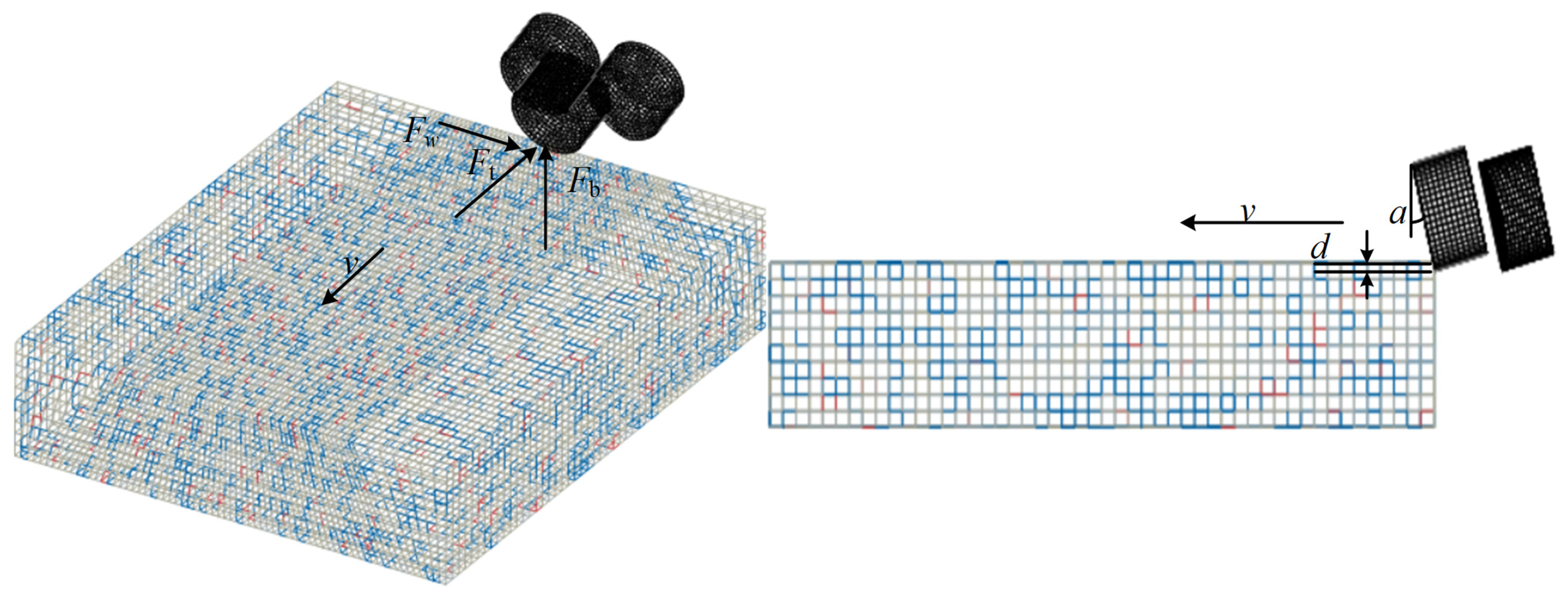
A finite element model of the mutual contact between the hybrid PDC cutter and the rock was constructed in ABAQUS2021 software, as shown in Figure 8, in which the preset back rake angle of each cutter is 15° and the depth of cut d is 1 mm, and the mesh size at the contact between the rock and the cutter is 0.8 mm and the size of the rest is 2 mm to take into account the calculation accuracy and efficiency. According to St. Venant's principle, the cutting-rock contact size should be 5 to 10 times the cutter size, therefore, the size of the rock is 100 mm × 80 mm × 20 mm. Set the speed of the PDC cutter along the cutting direction is 1 m/s, except for the rock surface and upper surface along the cutting direction of the cutter, the rest of the rock surface is fixed, to prevent the non-convergence phenomenon in the simulation process, the frictional contact relationship between the tool surface and the rock node is established in advance, and the friction factor is set to 0.25. The material parameters of the cutter during the simulation are: density 3600 kg/m3, modulus of elasticity 750 GPa, Poisson's ratio 0.07, and the materials used in the rock are shown in Table 1 above.

4. Results and Discussion

4.1. Rock-Breaking Characteristics Analysis

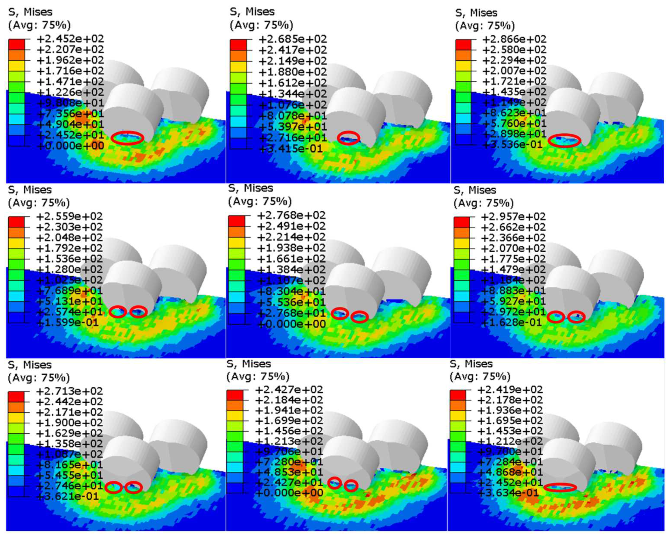
Figure 9 shows the stress contours during rock breaking when the cylindrical, axe, and triangular prism cutter are used as the front row, respectively, corresponding to the first, second, and third rows in the figure, unit MPa. As can be seen from Figure 9, the cylindrical cutter mainly uses the edge to shear the rock, while the axe and triangular prism cutters have a convex ridge-like structure that not only shears the rock but also crushes the center of the rock.
As can be seen from the red circle in Figure 9, the cylindrical cutter, due to shearing, contacts a larger volume of rock compared to the remaining two cutters, which may lead to a change in the damage mode of the rock from plastic small block damage to large block shedding, causing the cutter to repeatedly cut the rock chips, resulting in a decrease in the efficiency of the bit and an increase in the probability of vibration. The axe cutter has a convex ridge-like structure, and when it comes in contact with the rock, it splits the rock and distributes it on both sides of the cutter, effectively solving the problem of rock balling, which can make the rock break in a smaller volume compared to the cylindrical cutter and improve the rock breaking efficiency. Comparing the maximum stress in the contour, it is found that the stress on the rock is significantly greater when the axe cutter is used as the front row, indicating that the contact between the axe cutter and the rock is more likely to reach the yield stress of the rock, which can solve the problem that the cylindrical cutter is not easy to penetrate into the hard rock. The rock-breaking mode of the triangular prism cutter is similar to that of the axe cutter, but the crushing effect on the rock is not as strong as that of the axe cutter. From the comparison of the red circle position in the figure, it can be found that the rock separation effect under the action of the triangular prism cutter is not as obvious as that of the axe cutter, but the shape of the triangular prism cutter is symmetrical, and the efficiency should be more stable when the bit breaks the rock as a whole.
A comprehensive analysis of the rock-breaking characteristics of the cutters mentioned above reveals that axe cutters are suitable for the front row of the cutter blades of the PDC drill bit, and cylindrical and triangular prism cutters may be more suitable for the back row.

4.2. Cutting Force Analysis

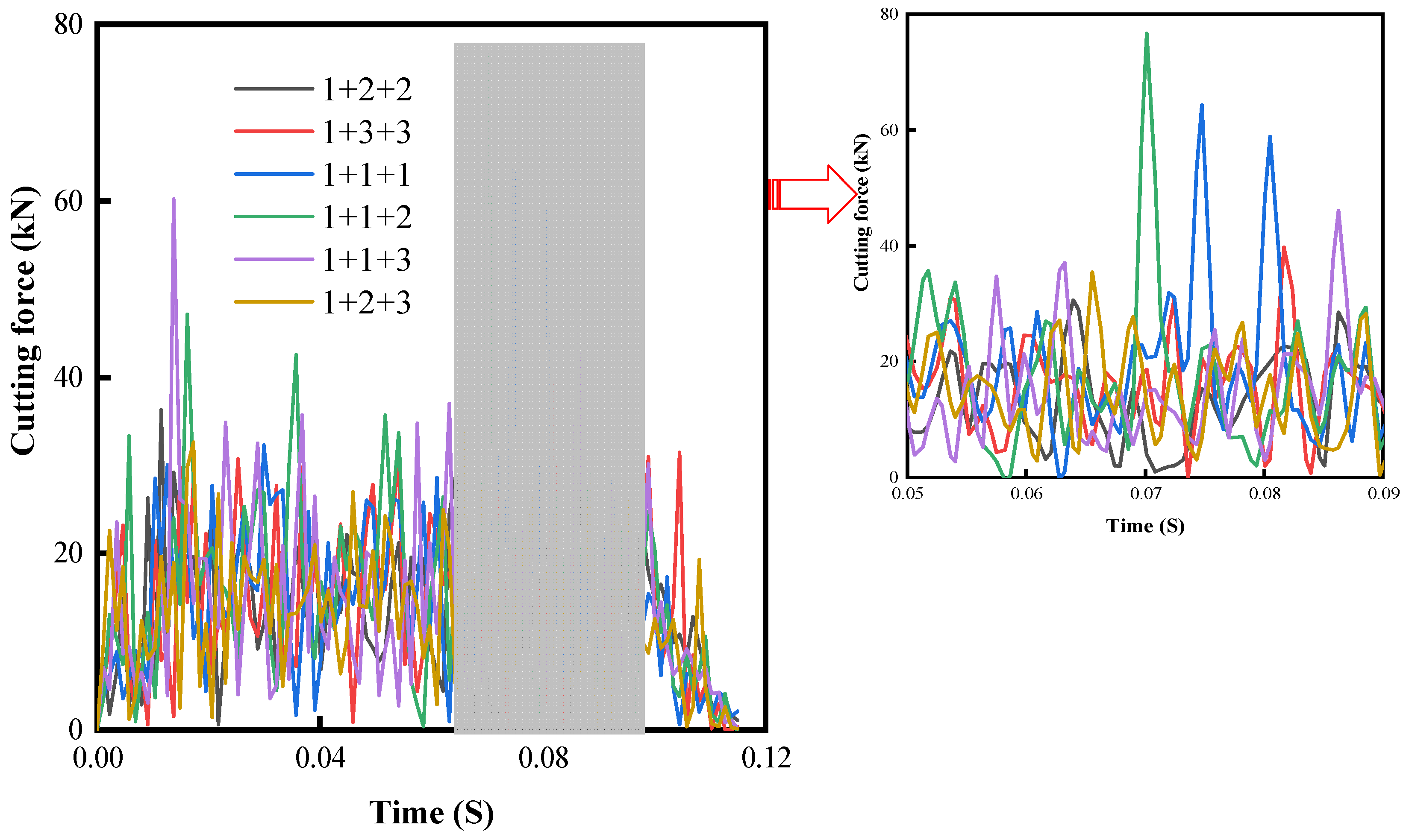
To find the best cutter arrangement scheme, 18 different combination schemes of cylindrical(No. 1), axe (No. 2), and triangular prism cutters (No. 3) were numerically simulated, among which the cutting force curves obtained for the six schemes with cylindrical cutters as the front row are shown in Figure. 10. Figure 10 shows that when the cylindrical cutter is used as the front row, the overall cutting force is greatly influenced by the different schemes of rear row arrangement, and the peak and fluctuation of cutting force are significantly larger than the rest of the schemes when the rear row is equipped with a cylindrical cutter.
The reason for this phenomenon has a lot to do with the rock-breaking characteristics of the cutter. The cutting surface of the cylindrical cutter is flat, and it mainly relies on the shear of the edge to break the rock, which is difficult to break when it encounters a hard rock, and if there are too many cylindrical cutters in the program, it will make it difficult to drill, resulting in an increase in resistance, which is very unfavorable to the overall efficiency and life of the drill bit.
It can also be seen from Figure 10 that when the cylindrical cutter is used as the front row and the axe cutter is used in the back row, the overall cutting force fluctuation is the smallest and the peak is lower. The reason is that the cylindrical cutter produces pre-crushing on the rock in the front row first, while the axe cutter itself has not only a shearing effect on the rock, but also a crushing effect, which is easier to penetrate into the granite compared to the cylindrical cutter, and the resistance is smaller.
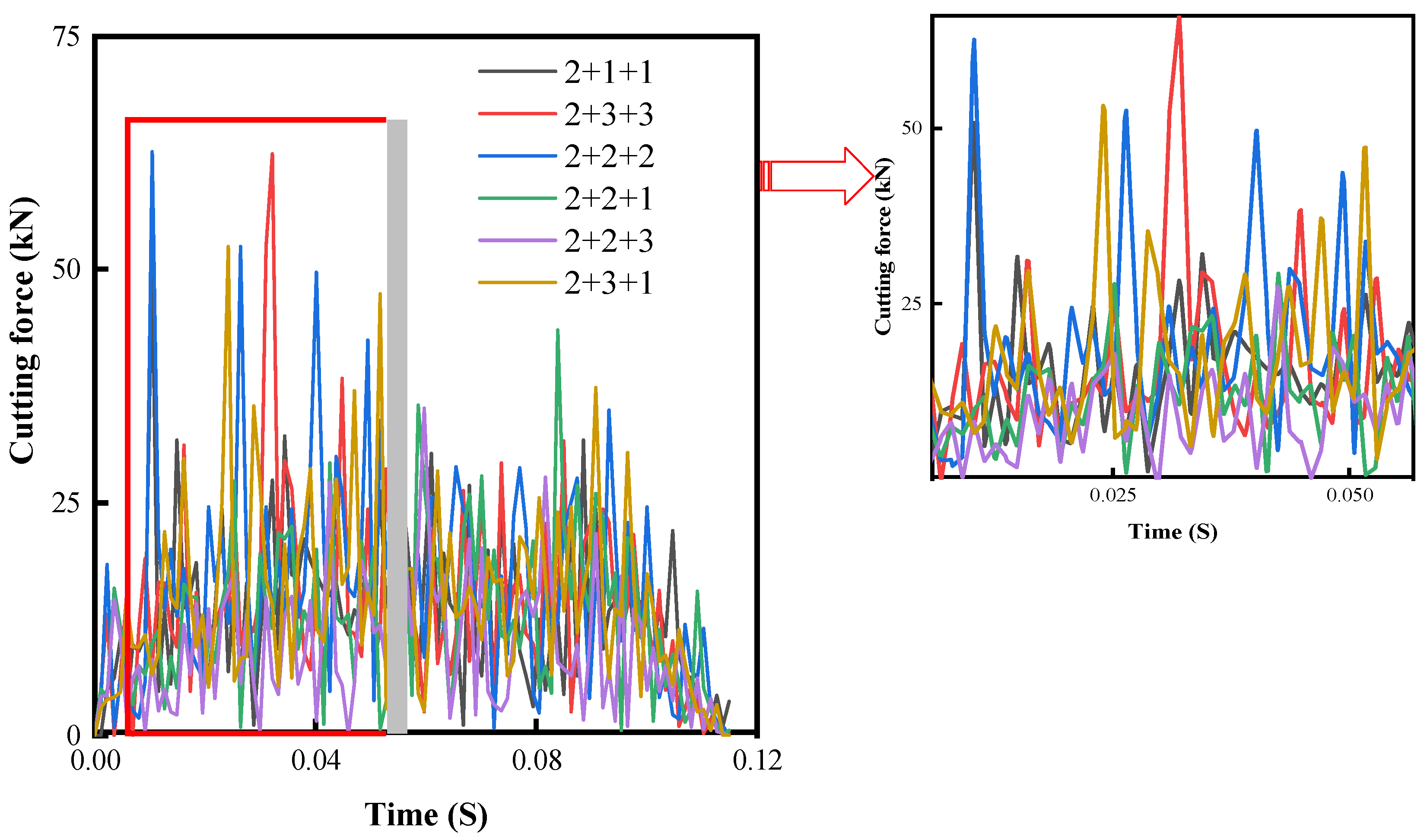
Figure 11 shows the cutting force curves for the axe cutter in the front row for six different scenarios. Figure 11 compares the data in Figure 10 and finds that when the axe cutter is used as the front row, the stress peaks of all scenarios are reduced compared to when the cylindrical cutter is the front row. The reason is that the axe cutter has a crushing effect on the rock compared to the cylindrical cutter, making it easier to penetrate into the granite overall at the beginning, producing a better pre-crushing effect and releasing the formation stress, allowing the back row of cutters to crush the rock more easily.
The data in Figure 11 also show that the effect of the front and rear rows of axe cutters is not ideal, because after the front row of axe cutters crush the rock, the back row of axe cutters crush the rock and interferes with the force of the front row of cutters so that the overall cutting force fluctuates and does not produce the desired effect. The peak and fluctuation of cutting forces are at a lower level when the front row is axe cutter and the back row is a triangular prism cutter and axe cutter, because the crushing effect of the triangular prism cutter on the rock is not as strong as the axe cutter, and the influence on the front row is small, and the cooperation between the two is better and the effect is ideal.
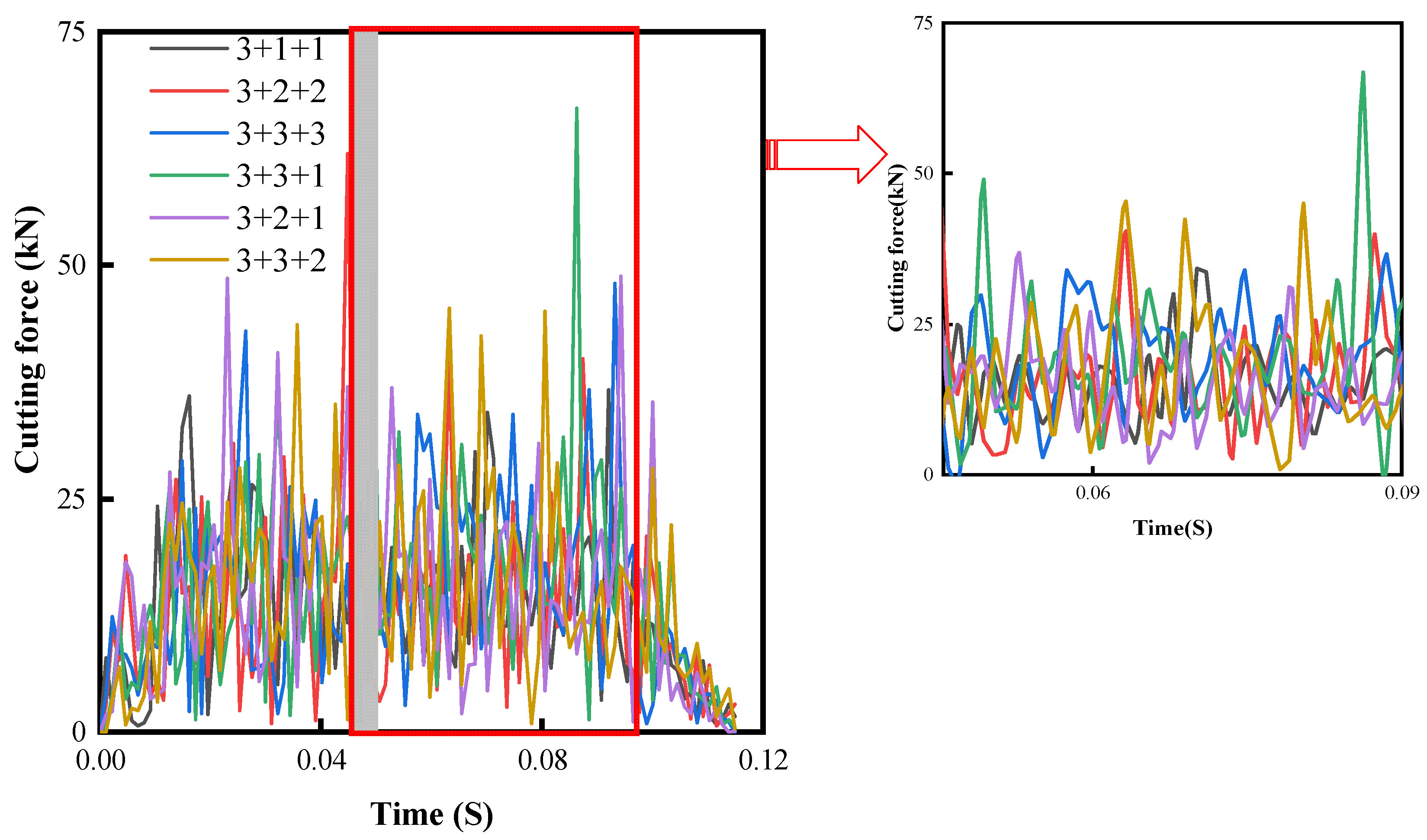
Figure 12 shows the cutting force curves for six different schemes with the triangular prism cutter as the front row. The data in Figure 12 shows that the overall cutting force fluctuation and the peak are at a lower level when the triangular prism cutter is used as the front row and the axe cutter is used in the back row. Compared with the scheme of cylindrical and axe cutter, the cutting force suffered by this scheme is smaller because the triangular prism cutter has a certain crushing effect on the rock and it is easier to break the granite. However, when the front row is axe cutter, the overall cutting force is the smallest, which also confirms the analysis in Figure 9 about the rock-breaking characteristics of the cutter.

4.3. Mechanical-Specific Energy Analysis

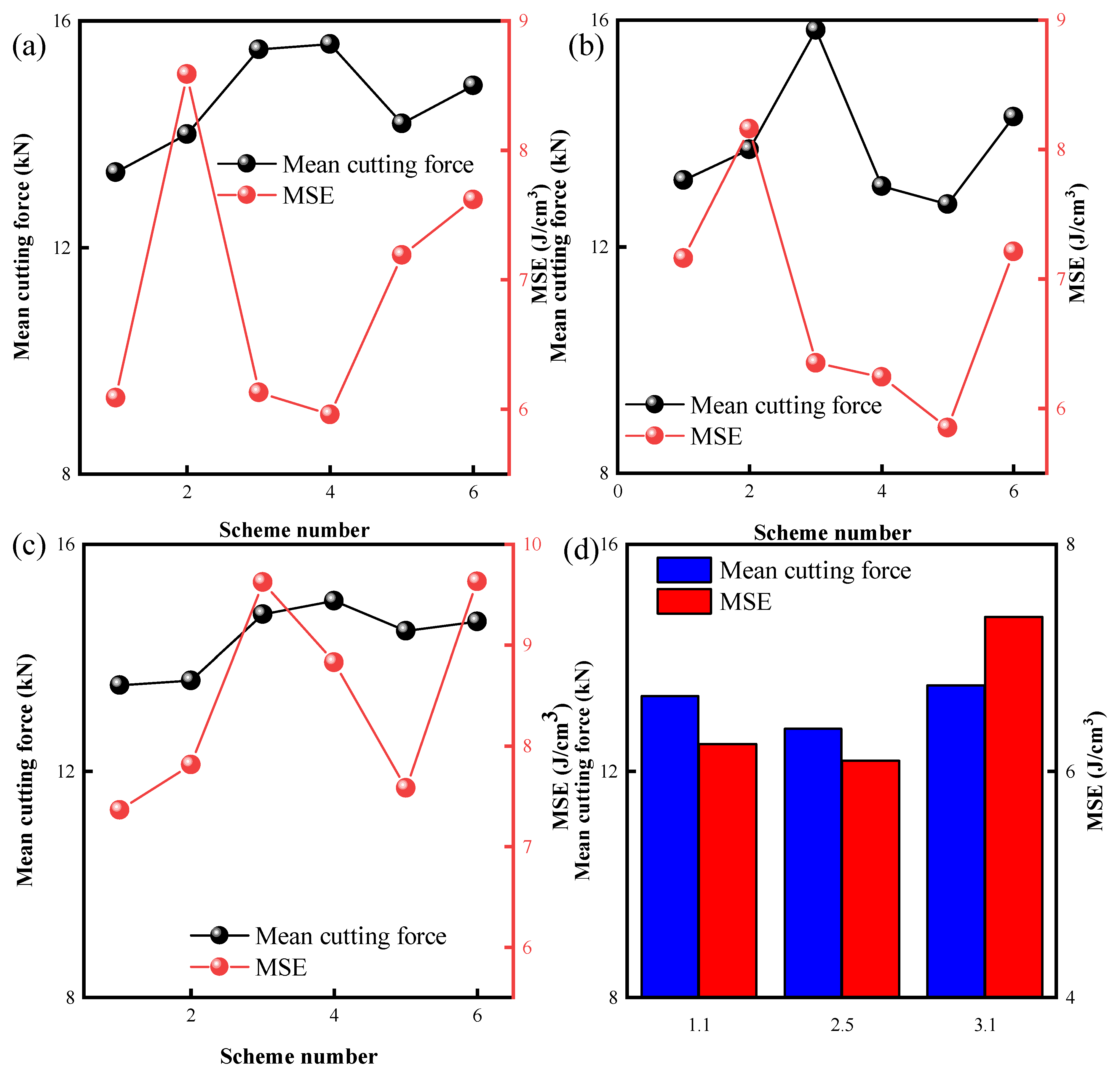
Figure 13a,b, and c show the mechanical specific energy(MSE) and cutting force averages for different scenarios with circular, axe, and triangular prism cutters as the front row, respectively, where the order of the scenario labels is the same as the order in the cutting force legend. Figure 13d shows the average value of cutting force and MSE for the best solution with three different cutters in the front row.
The data in Figure 13a shows that the overall average value of cutting force and MSE is minimum when the front row is a cylindrical cutter and the back row is arranged with all axe cutters, and the same reason the data in Figure 13b can be obtained that the axe cutter is the front row and the best combination with the triangular prism and axe cutter, and the data in Figure 13c shows that the triangular prism cutter is the front row and the best combination with the axe cutter. From the data in Figure 13d comparing the above three options, it is found that the overall best option is the axe cutter as the front row and the triangular prism axe cutter as the back row.
Figure 14a–c show the contact stress contours for the best scenarios with the cylindrical cutter as the front row, the axe cutter as the front row, and the triangular prism cutter as the front row, respectively. The data in the contours show that the overall stress on the cutter is the lowest when the axe cutter is in the front row, the second highest when the triangular prism cutter is in the front row, and the highest stress on the cutter when the cylindrical cutter is in the front row. The reason for the above phenomenon is that the axe cutter is the most aggressive, and after contact with the rock, it quickly releases the stratigraphic stress, making the back row of cutters able to break the rock with relative ease, while the maximum stress on the cutter as a whole tends to appear in the back row, so the maximum stress on the cutter as a whole is the smallest when the axe cutter is the front row.

5. Cutter Spacing Optimization and Bit Rock Breaking Simulation

To take full advantage of the hybrid cutter layout, it is necessary to make a reasonable choice of the spacing between the front and back rows of cutters. The cutter spacing parameters shown in Figure 6 have four parameters, and if the simulation is performed using manually modified parameters, there are too many options and, likely, the desired results will not be obtained. Because of this, the Box-Behnken response surface method [35] was used to optimize the cutter spacing to maximize the rock-breaking advantage of the hybrid cutter arrangement.

5.1. Analysis of Sampling Results

The front row of the axe cutter and the rear row of the triangular prism axe cutter were used as the study scenarios, and the longitudinal distances 1(A) and 2(B) and the transverse distances 1(C) and 2(D) of the front and rear rows of the cutter were the design variables (Figure 6), and the mean value of the cutting force applied to the cutter as a whole (E) was the target variable, and 17 sets of numerical simulations were performed using the Box-Behnken method sampling, and the results are shown in Table 2.
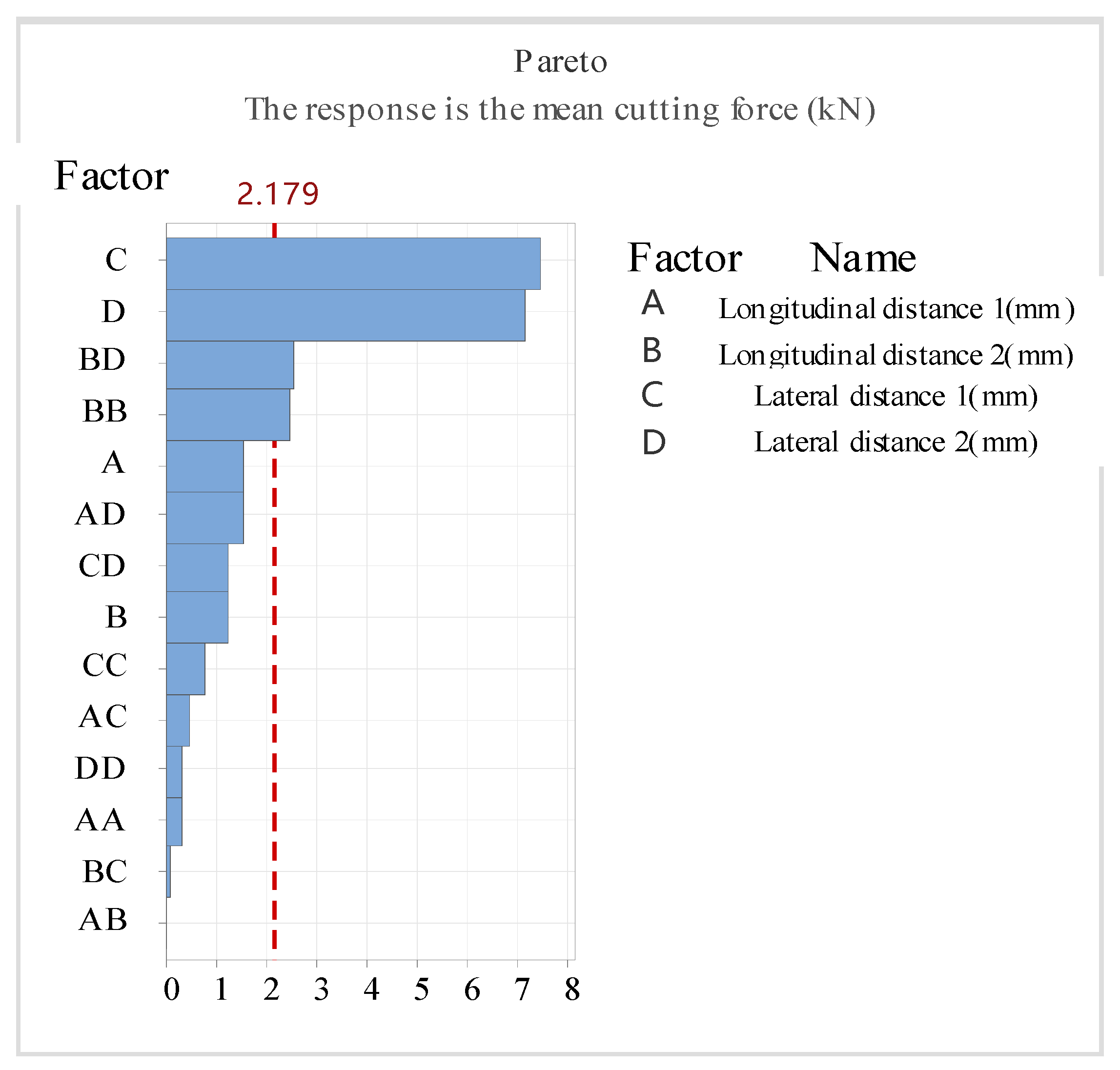
As can be seen from Table 2, the cutting force values of the cutter fluctuate considerably for different spacing cases, proving the importance of optimization. The results obtained were analyzed using MINITAB software to obtain a Pareto weight plot of the influence of each design variable on the target, as shown in Figure 15, where the factors exceeding the red line have a significant influence on the design target, which means that the interaction between transverse distance 1 and 2 and longitudinal distance 2 and transverse distance 2 has a greater influence on the overall mean value of the cutting force of the cutter.
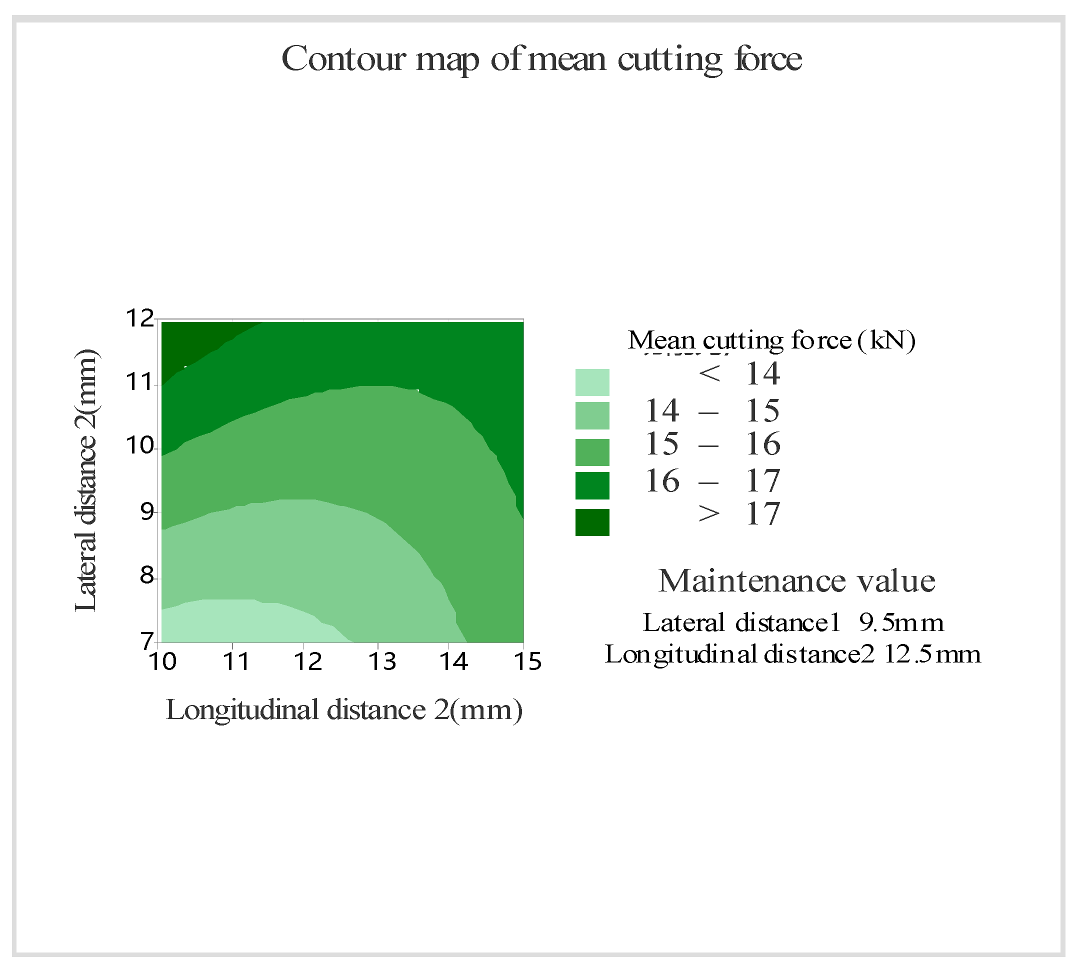
To facilitate the analysis of the interaction of factors B and D, the contour plot between the two and the mean value of the cutting force is drawn, as shown in Figure 16. The data in Figure 16 shows that the cutting force on the cutter increases with the increase of the transverse distance2 and the longitudinal distance2.To minimize the cutting force on the cutter, the transverse distance between the front and rear rows of cutters should be kept at 7 mm to 7.5 mm and the longitudinal distance should be kept at 10 mm to 12.5 mm. According to the weight of the influence of the factors on the target value, the MINITAB software was used to fit the design variables and The expression between the target values is:
E = 0.7 + 1.52 A 1.44 B 0.5 C + 2.35 D 0.0139 A 2 + 0.114 B 2 + 0.0374 C 2 + 0.0145 D 2 0.0018 A B 0.0264 A C 0.082 A D + 0.0051 B C 0.1347 B D + 0.0654 C D

5.2. Analysis of Optimization Results

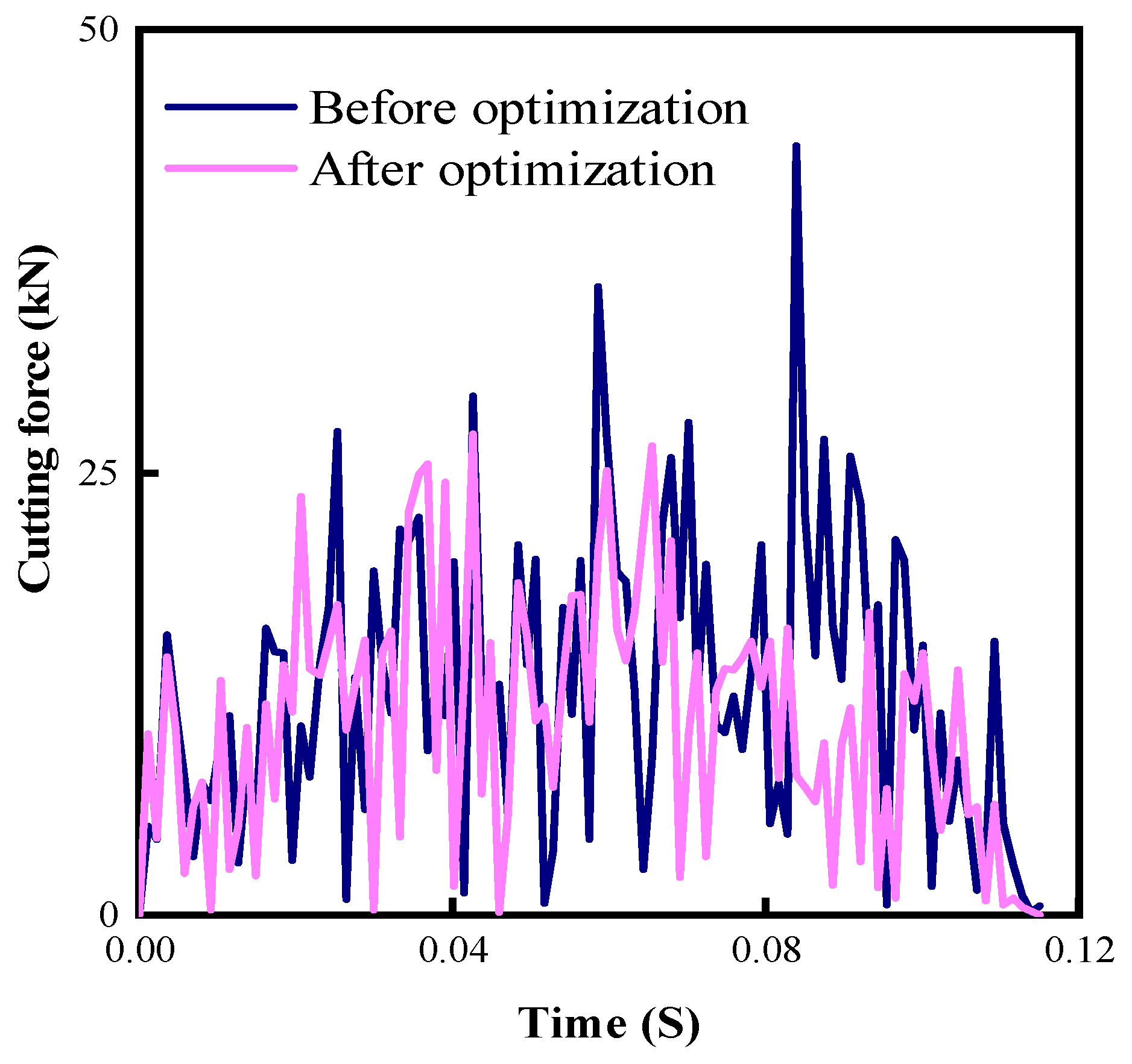
According to the expression between the obtained design variables and the target quantity, with the minimum mean cutting force as the optimization objective, the minimum mean cutting force of 11.68 kN is obtained when the resultant longitudinal distance 1 is 10 mm, longitudinal distance 2 is 10.06 mm, and transverse distances 1 and 2 are both 7 mm. numerical simulation of the tool for breaking rock based on the above parameters and comparison with the cutting force of the pre-optimization scheme As shown in Figure 17.
The data in Figure 17 shows that the peak and fluctuation of cutting force applied to the optimized cutter during rock breaking are significantly smaller than those before optimization, indicating that the optimized cutter solution is less resistant and more effective in the rock breaking process. The average value of cutting force applied to the optimized cutter is calculated to be 10.96 kN, which is about 13.7% less than the 12.7 kN before optimization. In addition, the error between the optimized predicted value and the simulated value is only 6.2%, which indicates that the obtained mathematical model is more reliable.

5.3. Full-Size Bit Rock Breaking Simulation

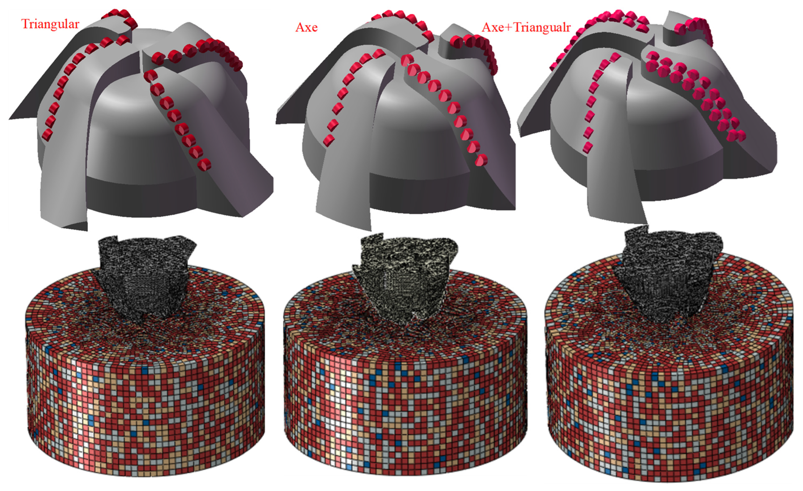
To fully understand the rock-breaking effect of the obtained optimal solution, the cutting structure of the PDC bit embedded by a triangular prism cutter, axe cutter, and mixed triangular prism and axe cutter with a diameter of 215.9 mm was established respectively, and the related finite element model was constructed in ABAQUS software as shown in Figure 18, with a formation diameter of 600 mm and a height of 300 mm. The layout of the cutter on the bit follows the principle of equal cutting volume, the grid size of the cutting structure of the bit is 4 mm, the size of the contact with the rock is 4 mm, and the grid size of the rest of the rock is 12 mm. The wear of the cutting structure of the bit is ignored in the simulation process, and it is considered as a rigid body, and the cutter is arranged with a back rake angle of 15° and a side rotation angle of 0°. Its rotation and vertical motion in the well are considered. The WOB is 80 kN and the RPM is 210 r/min. The rock is fixed except for the upper surface, and the simulation time is 15 s.
The contact between the simulated bit and the rock is a highly nonlinear process, which includes: (1) Material nonlinearity: the rock begins to deform plastically when it is subjected to more than the maximum stress it can withstand. (2) Geometric nonlinearity: The position of the bit is constantly changing during the interaction between rock and bit contact. (3) Contact nonlinearity: The contact surface between the bit and the rock is constantly changing as the rock disappears after breaking during the simulation. The above nonlinear process can cause the simulation to be difficult to converge. Based on D'Alembert's principle, the mechanical model of the contact process between the drill bit and the rock is established as follows:
T Q 0 0 T Y A t Q A t Y + C Q 0 0 C Y V t Q V t Y + K Q 0 0 K Y U t Q U t Y = S t Q F t Q S t Y F t Y
where T is the overall mass matrix of the finite element model; C is the overall damping matrix of the finite element model; K is the overall stiffness matrix; A is acceleration, V is velocity, and U is displacement; St is the WOB vector, and Ft is the contact force vector; the subscript Q represents the PDC cutter, and Y represents the rock.
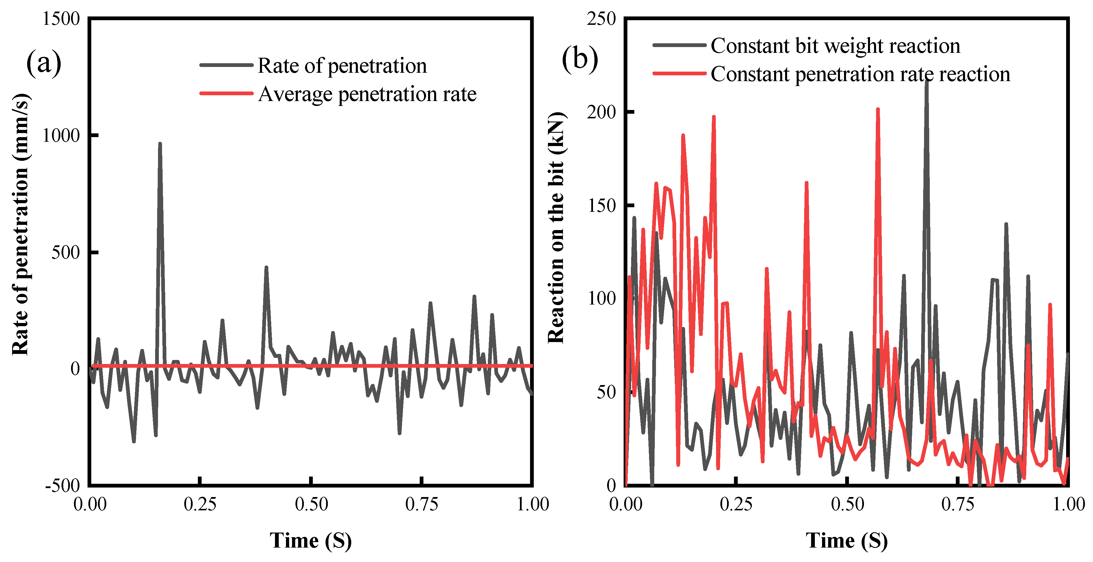
To verify the reliability of the simulation results of the full-size drill bit, a PDC bit with an axe cutter was applied with 60 kN WOB, 90 r/min RPM, and 1 s simulation time, and the mechanical ROP curve was obtained as shown in Figure 19a, and its average ROP was calculated to be 11.615 mm/s. Then a constant mechanical ROP of 11.615 mm/s was applied to the bit, and the reaction force is shown in Figure 19b. The mean value of the reaction force applied to the bit under constant WOB was calculated to be 47.65 kN, and the mean value of the reaction force under constant ROP was 51.92 kN, with an incorrectness of 8.9% between the two, which verified the accuracy of the numerical simulation to some extent.
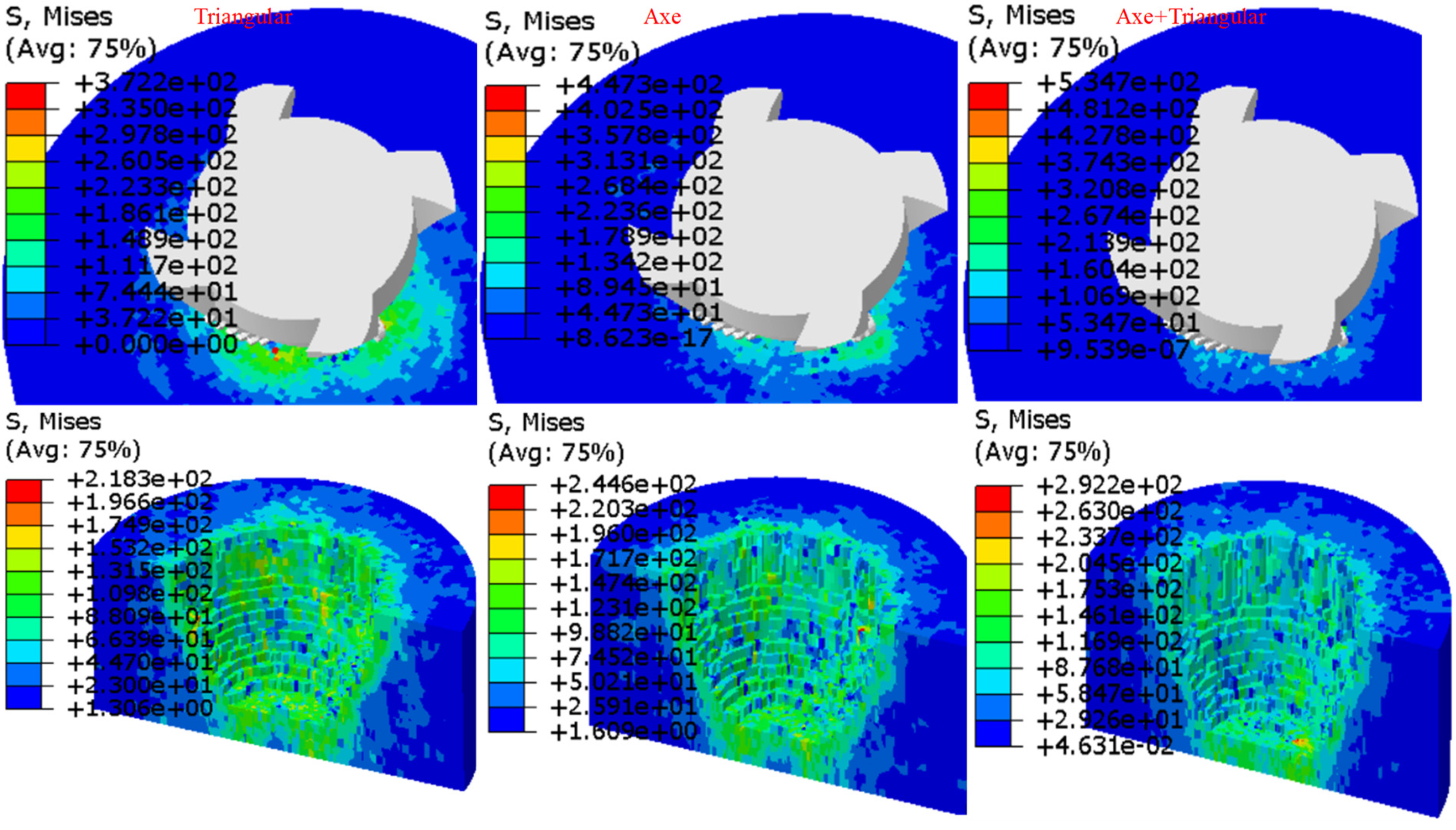
Figure 20 shows the rock stress contour during and after the completion of rock breaking for the three bits. From the contour, it can be seen that the bit with mixed cutters has the largest stress on the rock action, which means that the PDC bit with mixed cutters can more easily reach the yield stress of the rock when drilling, breaking it and penetrating into the granite more easily, which can avoid the phenomenon of stick-slip to a certain extent. In addition, according to the pictures, it is obvious to observe that the PDC bit with mixed cutter layout has the biggest displacement in feed, and the difference in feed between the bit with triangular prism cutter layout and the bit with axe cutter layout is not much, which means that the bit with mixed cutter layout can play a better effect.
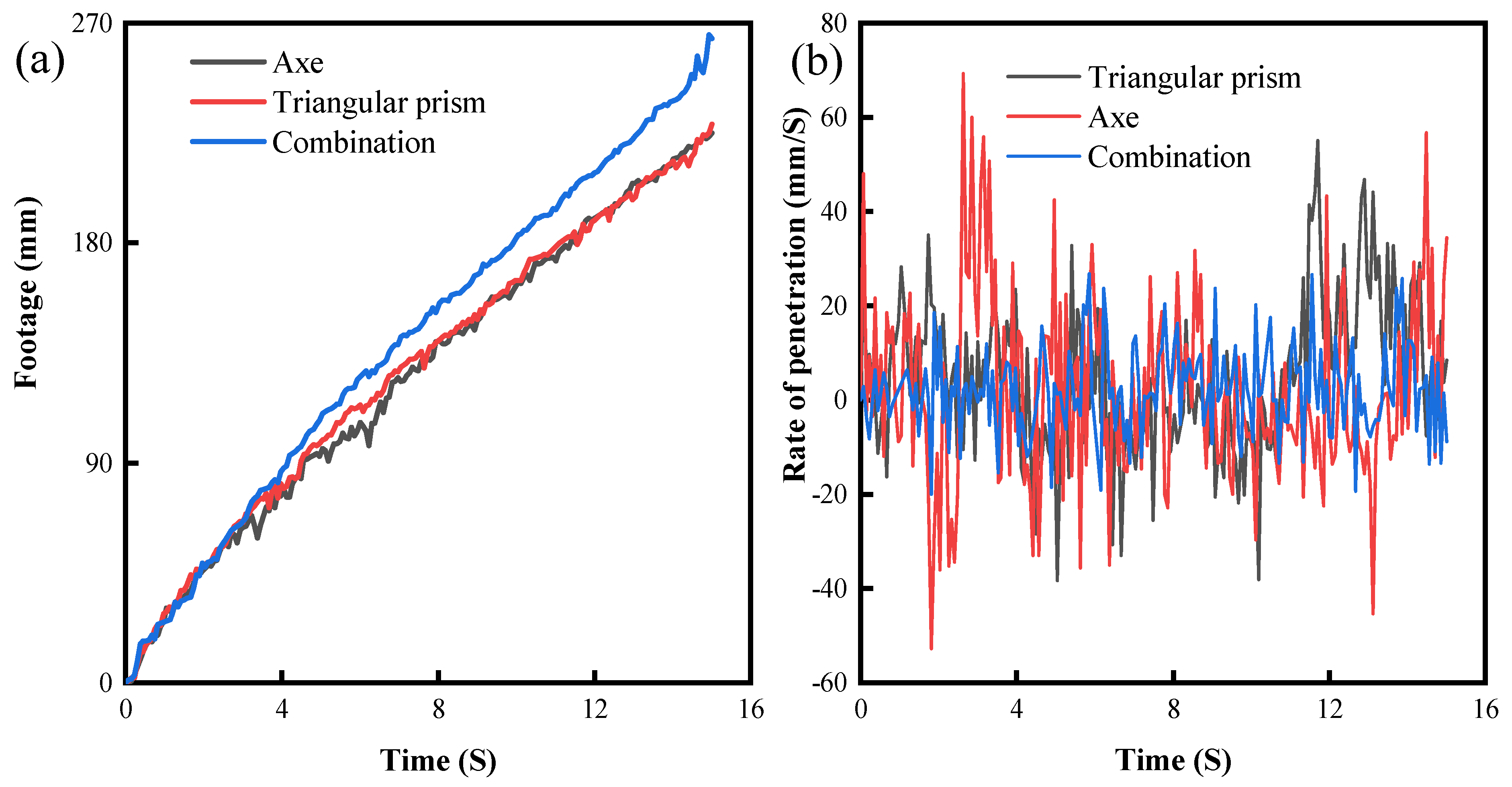
Figure 21a shows the bit footage curves of the three PDC bits in the rock-breaking process. The data in the figure show that the PDC bit with mixed cutters arrangement has a significantly greater bit footage, followed by the bit with triangular prism cutters arrangement, and finally the bit with axe cutters arrangement. Although the axe cutters are more aggressive, the triangular prism cutters’ structure is symmetrical, and the force during rock breaking is more balanced, which can maintain the stability of the drill bit drilling, so its efficiency is higher. The data in Figure 21a also show that due to the hardness of granite, the bit will produce displacement in the opposite direction of the applied WOB during rock breaking due to the inability to drill, which is very unfavorable for drilling, but it can be seen that the PDC bit with mixed cutter arrangement shows less displacement fluctuation, which indicates that it is less likely to bounce during drilling and can maintain the stability of WOB and ROP. It is calculated that the drilling displacement of the PDC bit with mixed cutter arrangement is 16.6% and 16.8% higher than that of the PDC bit with triangular prism and axe cutter, respectively.
Figure 21b shows the instantaneous ROP variation curve during the drilling process of the bit. The data show that the drill bit with mixed cutter has the smallest velocity fluctuation during the drilling process, indicating that the bit with mixed cutter penetrates into the granite more easily during the drilling process, which can reduce the occurrence of the sticky sliding phenomenon of the drill bit and improve the overall efficiency and life of the bit. This corresponds to the above analysis of the drill bit feed displacement. It is calculated that the ROP of the PDC bit with mixed cutter arrangement is 16.6% and 16.8% higher than that of the axe and triangular prism PDC bits, respectively.

5.4. Field Applications.

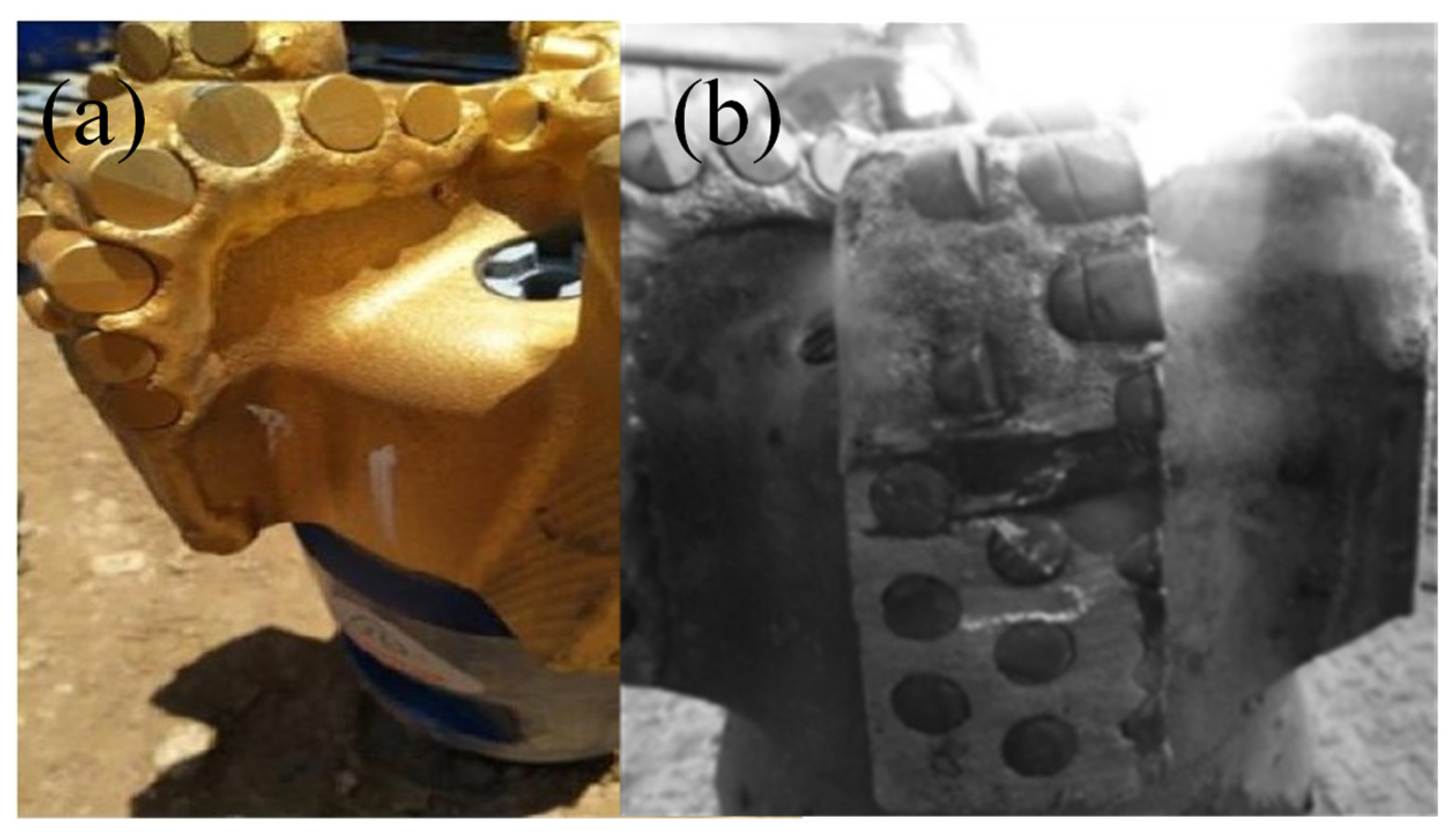
To verify the effect of the study, fieldwork was carried out in the Tahe oilfield in China using a bit with a triangular prism PDC cutter and a PDC bit with a mixed arrangement of cutters, and the effect of using a bit with a triangular prism cutter and a bit with a mixed arrangement of cutters was compared, provided that the drilling parameters and the nature of the formation and other conditions were almost identical.
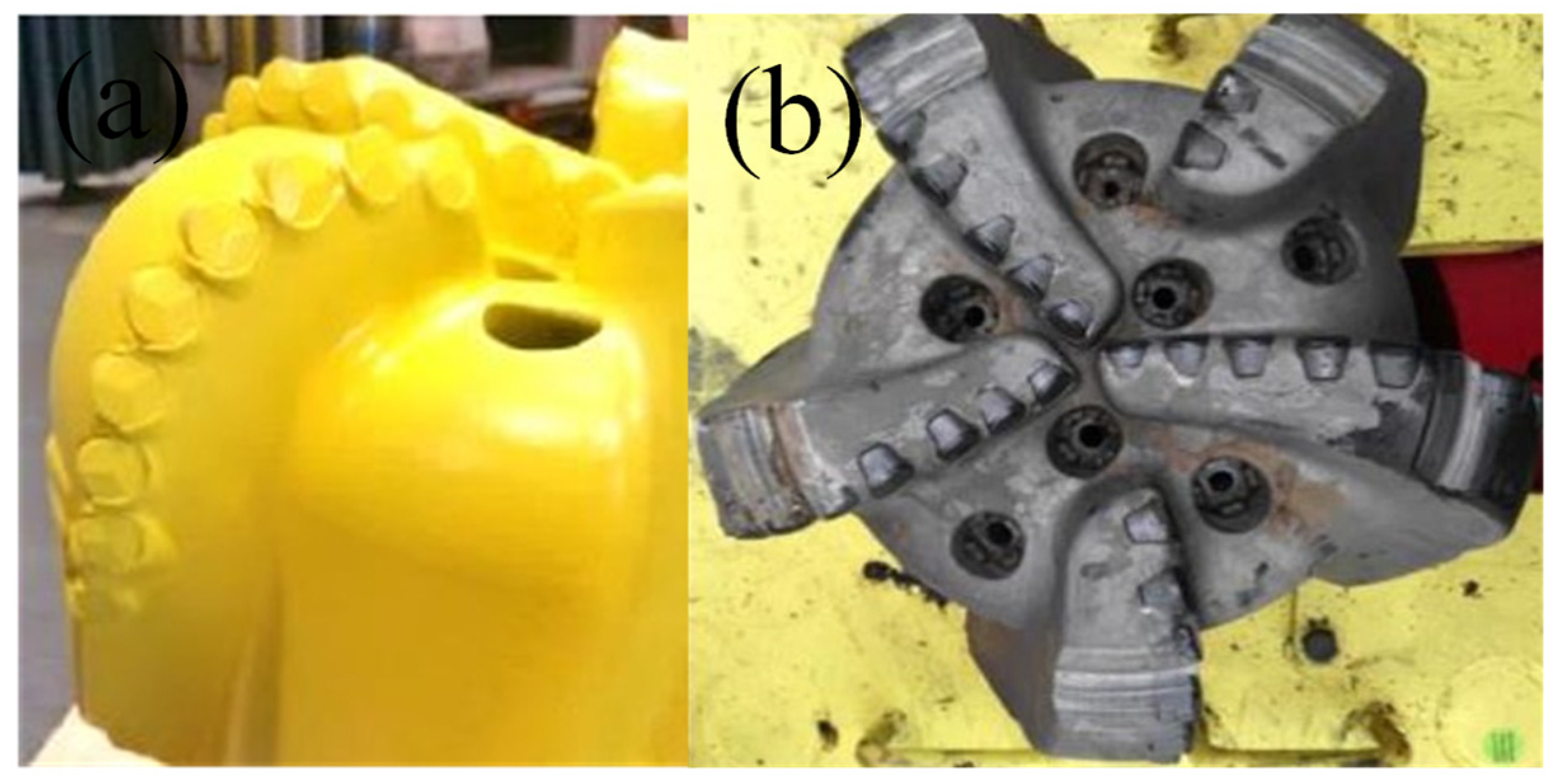
Figure 22 shows a comparison before and after the use of a bit with a triangular prism PDC cutter, and Figure 23 shows a comparison before and after the use of a bit with a mixed arrangement cutter. Both types of bits have a high degree of freshness of 85% or more after completion of drilling, and no chipping or bad cutter has occurred.
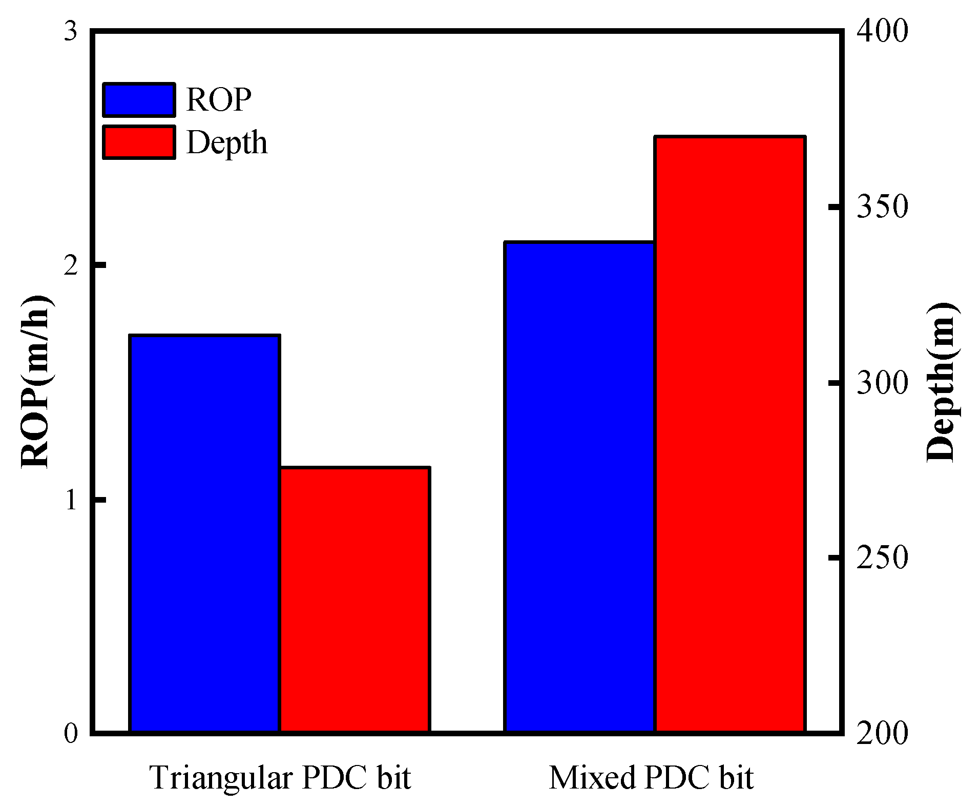
To compare the actual use of the two bits, the depth and ROP of both were recorded as shown in Figure 24. The data in Figure 24 shows that the ROP of the PDC bit with the mixed arrangement of cutters is 2.1 m/h, which is about a 23.5% improvement in ROP compared to the ROP of the PDC bit with triangular prism cutters of 1.7 m/h, which is closer to the numerical simulation results. The drilling depth of the PDC bit with a triangular prism cutter is 275.1 m, while the drilling depth of the PDC bit with a mixed cutter arrangement is 370.1 m, which is 34.5% higher than the drilling depth of the PDC bit.

6. Conclusions

In this study, three-dimensional finite element analysis was performed for different combination schemes of the axe, triangular prism, and cylindrical PDC cutters, and full-size drill bits to break inhomogeneous granite. A finite element model of the non-homogeneous granite was constructed, and the rock failure criterion was adopted by Drucker-Prager. uniaxial compression simulations of the rock model were used to verify the accuracy. The effect of different cutter type combination schemes on rock-breaking performance was studied, and the location parameters were optimized for the best scheme. The rock-breaking performance of PDC bits with the best scheme of cutter placement was investigated with single triangular prism cutter and single axe cutter bits. The following conclusions were drawn:
(1)
Compared with the cylindrical cutter, axe and triangular prism PDC cutters have not only a shear crushing effect on the rock but also a crushing effect, which is easier to penetrate into the hard rock. The crushing effect of the axe cutter is more obvious and aggressive, which is suitable for the front row of the blade, and the triangular prism cutter is more stable in drilling, which is suitable for the back row of the blade.
(2)
The axe cutter is in the front row, and the rear row arrangement of the triangular prism cutter and the axe cutter is the best solution. The optimal spacing is 10 mm transverse spacing and 7 mm longitudinal spacing between the rear row of the triangular prism cutter and the front row of the axe cutter, and 10.06 mm transverse spacing and 7 mm longitudinal spacing between the rear row of the axe cutter and the front row of cutters.
(3)
Compared with the PDC bit with axe cutter and triangular prism cutter, the PDC bit with the best combination for cutter placement has 16.8% and 16.6% higher footage respectively. The instantaneous ROP change during drilling is significantly less volatile and in a more stable state, which can effectively reduce the occurrence of stick-slip phenomenon, make it easier to penetrate into hard rock, maintain stable WOB, and keep efficient drilling.
(4)
The field application of the bit shows that the ROP and footage of the PDC drill bit with the mixed arrangement of cutters are significantly improved compared with the PDC bit with triangular prism cutters, which can effectively reduce the drilling cost in complex formations.

Author Contributions

Conceptualization, R.Y. and B.W.; methodology, W.Z.; software, R.Y.; validation, S.H and W.J.; formal analysis, R.Y.; investigation, W.Z.; resources, B.W.; data curation, R.Y.; writing—original draft preparation, R.Y.; writing—review and editing, B.W.; visualization, S.H.; supervision, B.W.; project administration, R.Y.; funding acquisition, B.W. All authors have read and agreed to the published version of the manuscript.

Funding

This research was funded by the China Oil and gas drilling equipment engineering technology Research Center fund project (Grant No. Z20257).

Conflicts of Interest

The authors declare no conflict of interest.

References

  1. Gao, D. Some research advances in well-engineering technology for unconventional hydrocarbon. Nat. Gas Ind. B 2022, 9, 41–50. [Google Scholar] [CrossRef]
  2. Zou, C.; Yang, Z.; He, D.; Wei, Y.; Li, J.; Jia, A.; Chen, J.; Zhao, Q.; Li, Y.; Li, J.; et al. Theory, technology, and prospects of conventional and unconventional natural gas. Pet. Explor. Dev. 2018, 45, 604–618. [Google Scholar] [CrossRef]
  3. Gu, J.; Huang, K. Role of Cobalt of Polycrystalline Diamond Compact (PDC) in Drilling Process. Diam. Relat. Mater. 2016, 66, 98–101. [Google Scholar] [CrossRef]
  4. Shao, F.; Liu, W.; Gao, D.; Zhao, X. Development and Verification of Triple-Ridge-Shaped Cutter for PDC Bits. SPE J. 2022, 27, 3849–3863. [Google Scholar] [CrossRef]
  5. Cheng, Z.; Li, G.; Huang, Z.; Sheng, M.; Wu, X.; Yang, J. Analytical Modelling of Rock Cutting Force and Failure Surface in Linear Cutting Test by Single PDC Cutter. J. Pet. Sci. Eng. 2019, 177, 306–316. [Google Scholar] [CrossRef]
  6. Ma, Y.; Huang, Z.; Li, Q.; Zhou, Y.; Peng, S. Cutter Layout Optimization for Reduction of Lateral Force on PDC Bit Using Kriging and Particle Swarm Optimization Methods. J. Pet. Sci. Eng. 2018, 163, 359–370. [Google Scholar] [CrossRef]
  7. Xi, Y.; Wang, W.; Fan, L.; Zha, C.; Li, J.; Liu, G. Experimental and Numerical Investigations on Rock-Breaking Mechanism of Rotary Percussion Drilling with a Single PDC Cutter. J. Pet. Sci. Eng. 2022, 208, 109227. [Google Scholar] [CrossRef]
  8. Zhang, Z.; Zhao, D.; Zhao, Y.; Gao, K.; Zhang, C.; Lü, X. 3D Numerical Simulation Study of Rock Breaking of the Wavy PDC Cutter and Field Verification. J. Pet. Sci. Eng. 2021, 203, 108578. [Google Scholar] [CrossRef]
  9. Dong, Z.; Zhang, H.; Li, J.; Zhang, K.; Ou, Y.; Lu, Z.; Shi, J. A Method for Evaluating the Rock Breaking Efficiency of Cutters and Optimizing the PDC Cutter Profile—A Study of Igneous Rock Formations in Shunbei Oilfield. Energies 2022, 15, 6686. [Google Scholar] [CrossRef]
  10. Xiong, C.; Huang, Z.; Yang, R.; Sheng, M.; Shi, H.; Dai, X.; Wu, X.; Zhang, S. Comparative Analysis Cutting Characteristics of Stinger PDC Cutter and Conventional PDC Cutter. J. Pet. Sci. Eng. 2020, 189, 106792. [Google Scholar] [CrossRef]
  11. Ayop, A.Z.; Bahruddin, A.Z.; Maulianda, B.; Prakasan, A.; Dovletov, S.; Atdayev, E.; Rani, A.M.A.; Elraies, K.A.; Ganat, T.A.; Barati, R.; et al. Numerical Modeling on Drilling Fluid and Cutter Design Effect on Drilling Bit Cutter Thermal Wear and Breakdown. J. Pet. Explor. Prod. Technol. 2020, 10, 959–968. [Google Scholar] [CrossRef]
  12. Li, S.; Zhu, X.; Liang, K.; Deng, Y.; Liu, H. Numerical Simulation Study on Optimizing the Conical Cutter Bit to Break Deep Strata. Recent Pat. Eng. 2023, 18. [Google Scholar] [CrossRef]
  13. Crane, D.; Zhang, Y.; Douglas, C.; Song, H.; Gan, X.; Lin, Z.; Mueller, L.; Skoff, G.; Self, J.; Krough, B. Innovative PDC Cutter with Elongated Ridge Combines Shear and Crush Action to Improve PDC Bit Performance. In Proceedings of the Day 3 Wed, March 08, 2017; SPE: Manama, Kingdom of Bahrain, 2017; p. D031S014R004. [Google Scholar]
  14. Shao, F.; Liu, W.; Gao, D.; Ye, Y. Study on Rock-Breaking Mechanism of Axe-Shaped PDC Cutter. J. Pet. Sci. Eng. 2021, 205, 108922. [Google Scholar] [CrossRef]
  15. Yoan Mardiana, R.; Pasaribu, S. The Effects of PDC Cutter Geometries to the Drilling Dynamics in Various Geothermal Rocks: A Comprehensive Study Using Advanced Drilling Dynamics Simulation. IOP Conf. Ser. Earth Environ. Sci. 2022, 1014, 012006. [Google Scholar] [CrossRef]
  16. Kunshin, A.A.; Buslaev, G.V.; Reich, M.; Ulyanov, D.S.; Sidorkin, D.I. Numerical Simulation of Nonlinear Processes in the “Thruster—Downhole Motor—Bit” System While Extended Reach Well Drilling. Energies 2023, 16, 3759. [Google Scholar] [CrossRef]
  17. Wang, C.; Li, S.; Zhang, L. Evaluation of Rock Abrasiveness Class Based on the Wear Mechanisms of PDC Cutters. J. Pet. Sci. Eng. 2019, 174, 959–967. [Google Scholar] [CrossRef]
  18. Zeng, Y.; He, W.; Zhang, Z.; Shi, H.; Zhou, J.; Ding, S.; Ma, G. Rock-Breaking Performances of Innovative Triangular-Shaped Polycrystalline Diamond Compact Cutter. Rev. Sci. Instrum. 2021, 92, 035115. [Google Scholar] [CrossRef]
  19. Liu, J.; Zheng, H.; Kuang, Y.; Xie, H.; Qin, C. 3D Numerical Simulation of Rock Cutting of an Innovative Non-Planar Face PDC Cutter and Experimental Verification. Appl. Sci. 2019, 9, 4372. [Google Scholar] [CrossRef]
  20. Chen, C.; Yan, J.; Zou, Y.; Luo, H. Geometric Evolvement, Simulation, and Test of a Bionic Lateral PDC Reamer Bit Inspired by Capra Sibirica Horn. Appl. Bionics Biomech. 2022, 2022, 1–11. [Google Scholar] [CrossRef]
  21. Huang, Z.; Xie, D.; Xie, B.; Zhang, W.; Zhang, F.; He, L. Investigation of PDC Bit Failure Base on Stick-Slip Vibration Analysis of Drilling String System plus Drill Bit. J. Sound Vib. 2018, 417, 97–109. [Google Scholar] [CrossRef]
  22. Tian, K.; Detournay, E. Influence of PDC Bit Cutter Layout on Stick–Slip Vibrations of Deep Drilling Systems. J. Pet. Sci. Eng. 2021, 206, 109005. [Google Scholar] [CrossRef]
  23. Wang, Y.; Ni, H.; Wang, R.; Huang, B.; Liu, S.; Zhang, H. Numerical Simulation Research on Cutting Rock with a PDC Cutter Assisted by an Impact Force. Adv. Civ. Eng. 2022, 2022, 1–9. [Google Scholar] [CrossRef]
  24. Akbari, B.; Miska, S. The Effects of Chamfer and Back Rake Angle on PDC Cutters Friction. J. Nat. Gas Sci. Eng. 2016, 35, 347–353. [Google Scholar] [CrossRef]
  25. Zhu, X.; Dan, Z. Numerical Simulation of Rock Breaking by PDC Bit in Hot Dry Rocks. Nat. Gas Ind. B 2019, 6, 619–628. [Google Scholar] [CrossRef]
  26. Jamaludin, A.A.; Mehat, N.M.; Kamaruddin, S. Investigating the Effects of PDC Cutters Geometry on ROP Using the Taguchi Technique. J. Phys. Conf. Ser. 2017, 908, 012041. [Google Scholar] [CrossRef]
  27. Lam, K.Y.; Nélieu, S.; Benoit, P.; Passeport, E. Optimizing Constructed Wetlands for Safe Removal of Triclosan: A Box–Behnken Approach. Environ. Sci. Technol. 2020, 54, 225–234. [Google Scholar] [CrossRef] [PubMed]
  28. Silva, T.P.; Ferreira, A.N.; De Albuquerque, F.S.; De Almeida Barros, A.C.; Da Luz, J.M.R.; Gomes, F.S.; Pereira, H.J.V. Box–Behnken Experimental Design for the Optimization of Enzymatic Saccharification of Wheat Bran. Biomass Convers. Biorefinery 2022, 12, 5597–5604. [Google Scholar] [CrossRef]
  29. Bass, J.D. Elasticity of Minerals, Glasses, and Melts. In AGU Reference Shelf; Ahrens, T.J., Ed.; American Geophysical Union: Washington, DC, USA, 2013; ISBN 978-1-118-66819-1. [Google Scholar]
  30. Zhang, Y.; Wong, L.N.Y.; Chan, K.K. An Extended Grain-Based Model Accounting for Microstructures in Rock Deformation. J. Geophys. Res. Solid Earth 2019, 124, 125–148. [Google Scholar] [CrossRef]
  31. Peng, J.; Wong, L.N.Y.; Teh, C.I.; Li, Z. Modeling Micro-Cracking Behavior of Bukit Timah Granite Using Grain-Based Model. Rock Mech. Rock Eng. 2018, 51, 135–154. [Google Scholar] [CrossRef]
  32. Hofmann, H.; Babadagli, T.; Zimmermann, G. A Grain Based Modeling Study of Fracture Branching during Compression Tests in Granites. Int. J. Rock Mech. Min. Sci. 2015, 77, 152–162. [Google Scholar] [CrossRef]
  33. Wang, L, Bo L, Feng L. Mechanical properties of heterogeneous rock under uniaxial compression based on mineral crystal model. Chinese Journal of Geotechnical Engineering 2020, 42, 542–550. (In Chinese) [CrossRef]
  34. Zhang, Z.; Zhao, D.; Zhao, Y.; Zhou, Y.; Tang, Q.; Han, J. Simulation and Experimental Study on Temperature and Stress Field of Full-Sized PDC Bits in Rock Breaking Process. J. Pet. Sci. Eng. 2020, 186, 106679. [Google Scholar] [CrossRef]
  35. El-Sheikh, S.M.; Barhoum, A.; El-Sherbiny, S.; Morsy, F.; El-Midany, A.A.-H.; Rahier, H. Preparation of Superhydrophobic Nanocalcite Crystals Using Box–Behnken Design. Arab. J. Chem. 2019, 12, 1479–1486. [Google Scholar] [CrossRef]
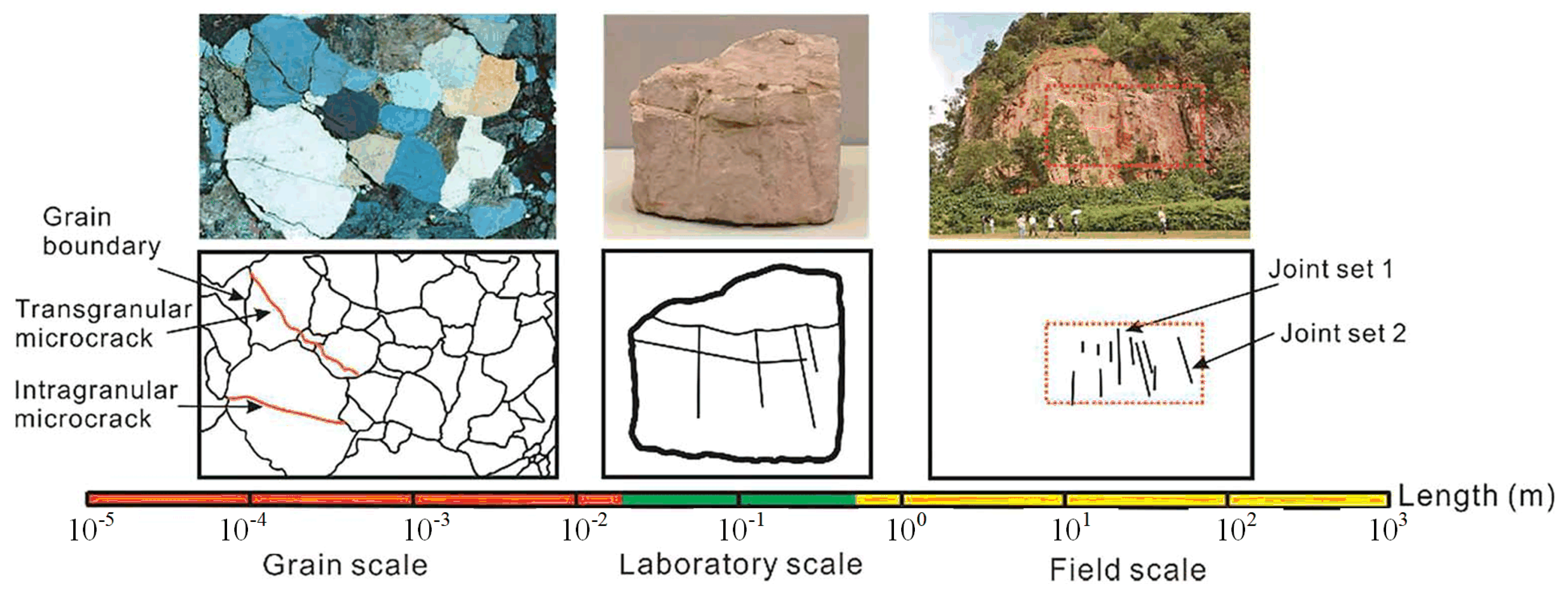
Figure 1. Composition of heterogeneous granite [30].
Preprints 80228 g001
Figure 2. Rock model.
Preprints 80228 g002
Figure 3. Crack comparison.
Preprints 80228 g003
Figure 4. Comparison of stress-strain curves.
Preprints 80228 g004
Figure 5. PDC cutters with different shapes.
Preprints 80228 g005
Figure 6. Model simplification.
Preprints 80228 g006
Figure 7. Interaction between PDC cutters and rocks.
Preprints 80228 g007
Figure 8. Finite element model.
Preprints 80228 g008
Figure 9. Stress contour of the PDC cutter during the rock-breaking process.
Preprints 80228 g009
Figure 10. Different cutting forces with cylindrical cutter in the front row.
Preprints 80228 g010
Figure 11. Axe cutter with different cutting forces for the front row.
Preprints 80228 g011
Figure 12. Different cutting forces with triangular prism cutters in the front row.
Preprints 80228 g012
Figure 13. Comparison of Mechanical Specific Energy and Mean Cutting Force.
Preprints 80228 g013
Figure 14. Contact stress contour: (a) Circular cutter as front row; (b) Axe cutter as front row;(c) Triangular-shaped cutter as front row.
Preprints 80228 g014
Figure 15. The picture of Pareto.
Preprints 80228 g015
Figure 16. Contour map.
Preprints 80228 g016
Figure 17. Comparison of cutting forces before and after optimization.
Preprints 80228 g017
Figure 18. Drill cutting structure and finite element model.
Preprints 80228 g018
Figure 19. Bit numerical simulation verification.
Preprints 80228 g019
Figure 20. Stress contour of rock broken by a bit.
Preprints 80228 g020
Figure 21. Bit penetration rate and displacement comparison.
Preprints 80228 g021
Figure 22. Effect of using bit: (a) Before using the triangular prism bit; (b) After use of the triangular prism PDC bit.
Preprints 80228 g022
Figure 23. Effect of using bit: (a) Before using the bit with mixed arrangement cutter; (b) After use of bit with mixed arrangement cutter.
Preprints 80228 g023
Figure 24. Data from the actual drilling process of the bit.
Preprints 80228 g024
Table 1. Material parameters of each component in granite.
Parameters Quartz Mineral Feldspar Mineral Mica Mineral Other Mineral
Volume content /(%) 24 49 24 3
Density /(kg/m3) 2650 2600 3050 1650
Elastic /(GPa) 51 42 33 24
Linear stiffness ratio 1.1 1.3 1.7 3.7
Parallel modulus of elasticity 51 42 33 24
Bonding stiffness ratio 1.1 1.3 1.7 3.7
Tensile strength /(MPa) 126±16 105±16 98±13 77±9
Bonding strength /(MPa) 196±42 162±28 146±22 105±0
Friction angle /(°) 19.5 22.4 17.3 23.7
Table 2. Sampling points.
Serial Number Factors Cutting Force break//Average Value E/kN
A/mm B/mm C/mm D/mm
1 15.0 12.5 12.0 9.5 16.7153
2 12.5 15.0 7.0 9.5 14.4970
3 12.5 12.5 12.0 12.0 18.6900
4 15.0 12.5 9.5 12.0 15.7510
5 10.0 10.0 9.5 9.5 14.5990
6 12.5 12.5 9.5 9.5 15.1812
7 15.0 12.5 9.5 7.0 14.7283
8 10.0 12.5 12.0 9.5 16.0326
9 15.0 12.5 7.0 9.5 14.6482
10 10.0 12.5 9.5 7.0 13.7766
11 15.0 10.0 9.5 9.5 15.4635
12 12.5 10.0 7.0 9.5 14.6482
13 12.5 12.5 9.5 9.5 15.1812
14 10.0 12.5 7.0 9.5 14.2570
15 12.5 12.5 7.0 7.0 13.2620
16 12.5 12.5 9.5 9.5 15.1812
17 12.5 15.0 12.0 9.5 18.2124
Disclaimer/Publisher’s Note: The statements, opinions and data contained in all publications are solely those of the individual author(s) and contributor(s) and not of MDPI and/or the editor(s). MDPI and/or the editor(s) disclaim responsibility for any injury to people or property resulting from any ideas, methods, instructions or products referred to in the content.
Copyright: This open access article is published under a Creative Commons CC BY 4.0 license, which permit the free download, distribution, and reuse, provided that the author and preprint are cited in any reuse.
Prerpints.org logo

Preprints.org is a free preprint server supported by MDPI in Basel, Switzerland.

Subscribe

© 2024 MDPI (Basel, Switzerland) unless otherwise stated