Submitted:
22 July 2023
Posted:
26 July 2023
You are already at the latest version
Abstract
Keywords:
1. Introduction
2. Material and Methods
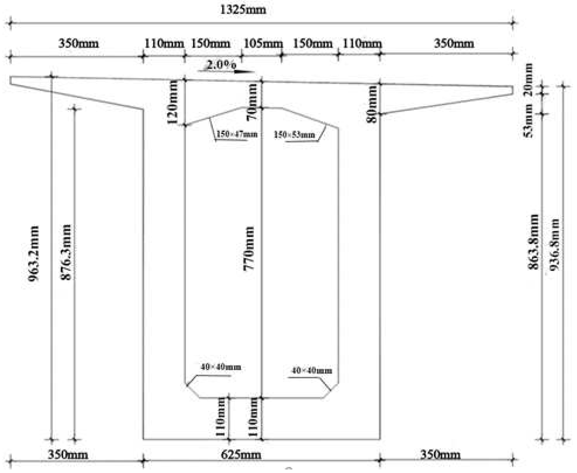
2.1. Project Profile
2.2. Structure of Rhombus Rraveling Track of Hanging Basket
2.2.1. Structure of Walking Track
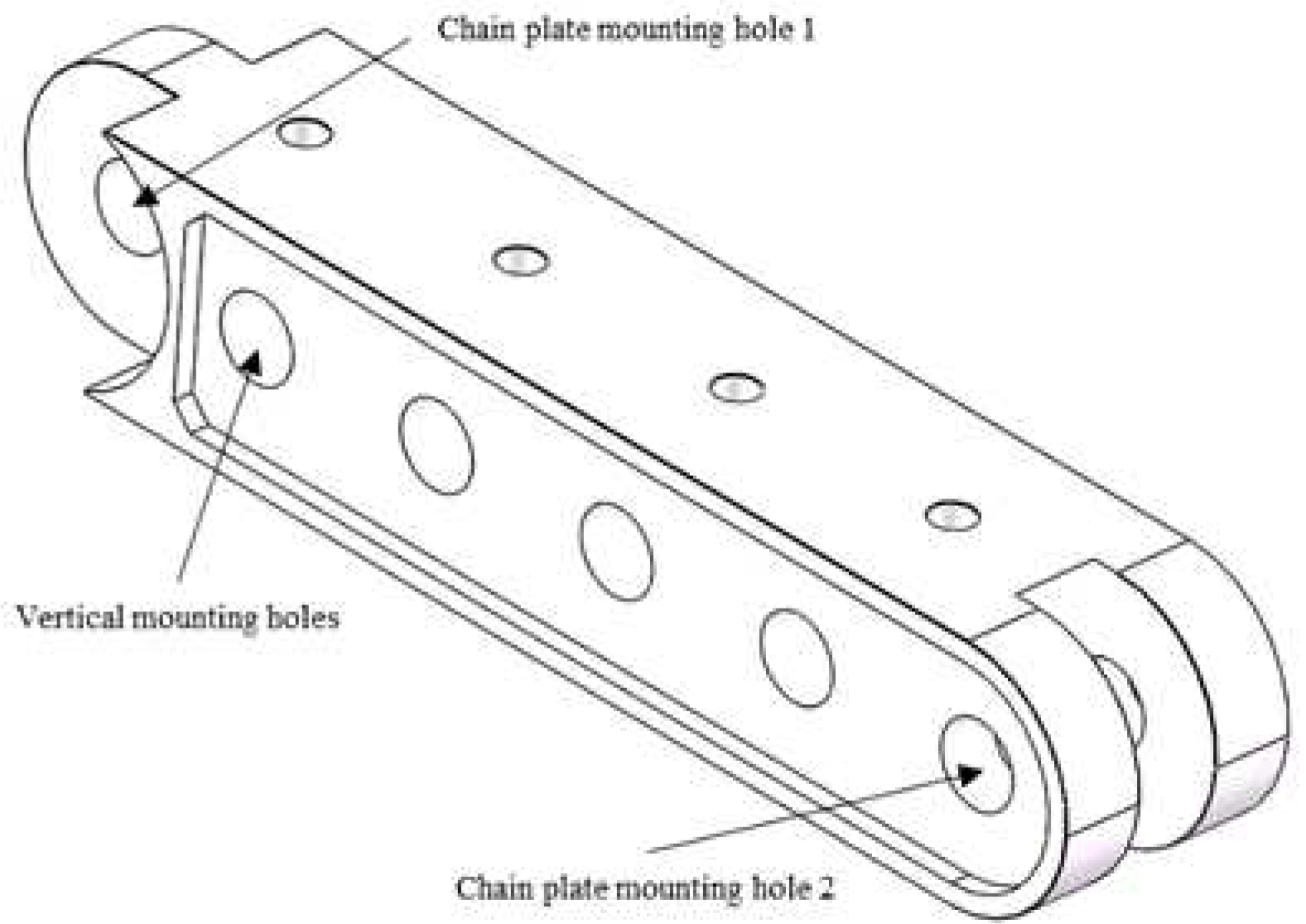
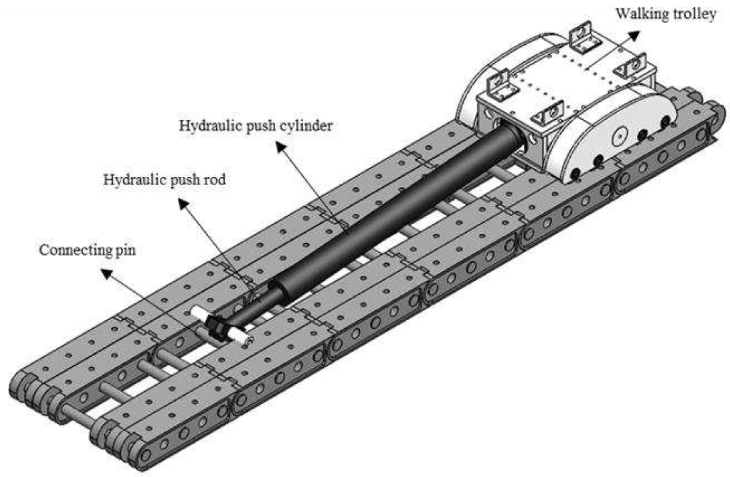
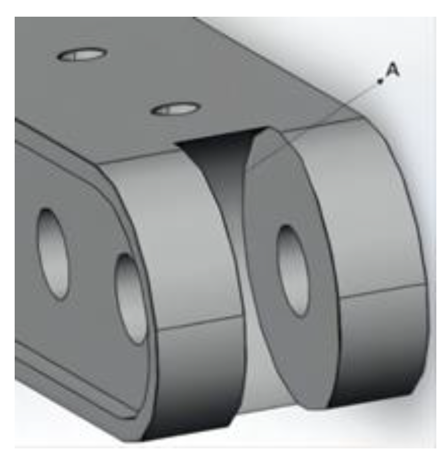
- A. Introduction to the Structure of Walking Track
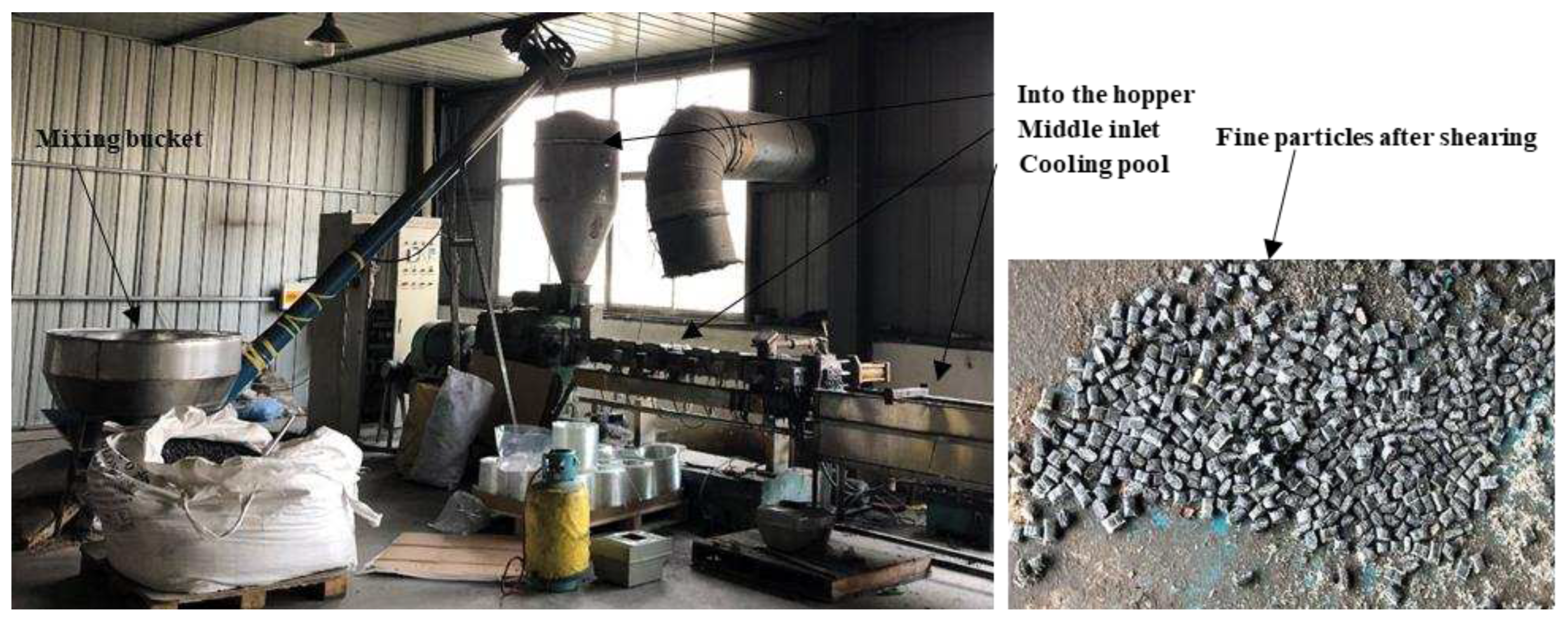
- B. Preparation of Walking Track
- C. Material performance test of Walking Track
- 1. Tensile Property Test
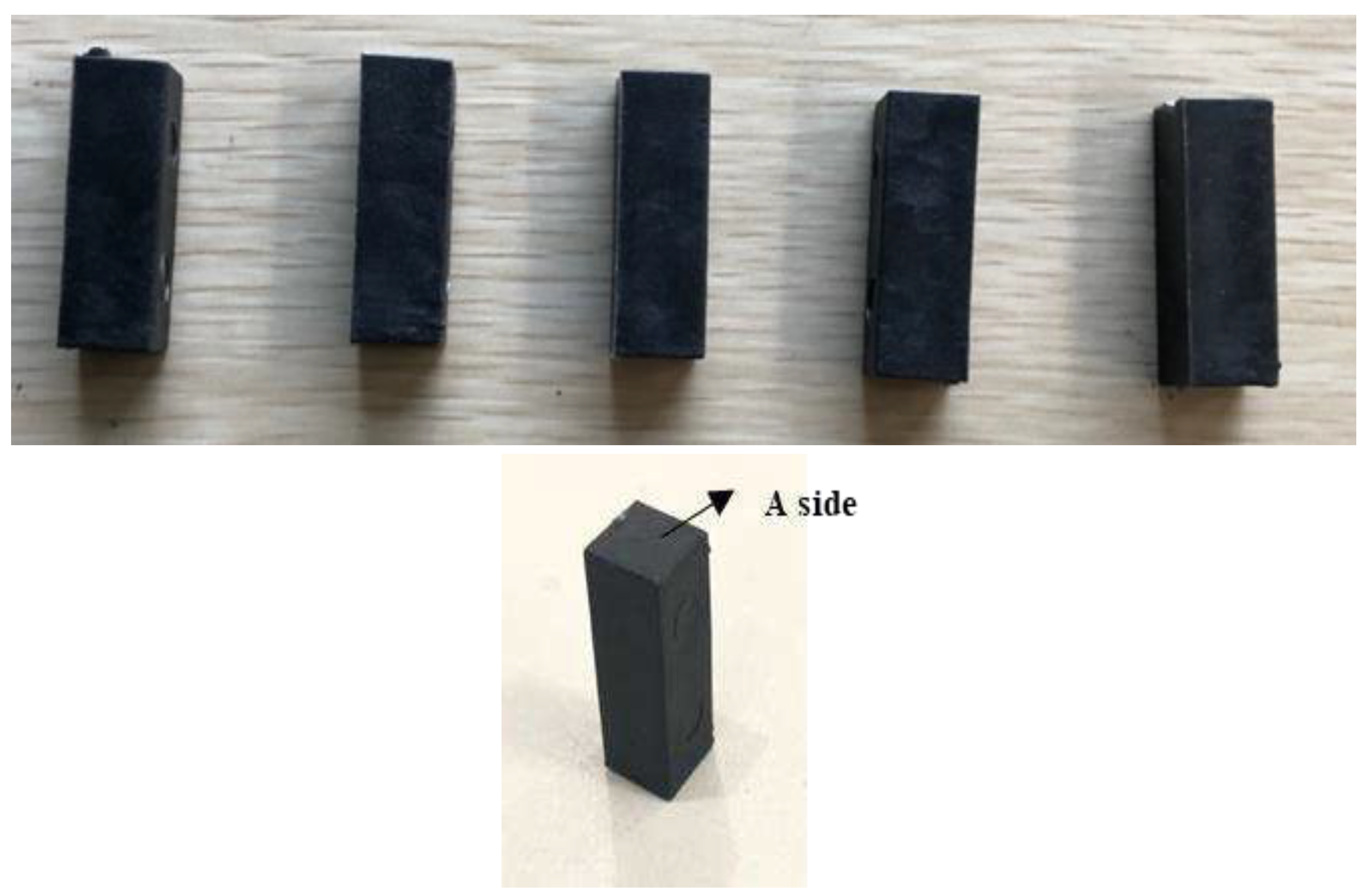
- 2. Compressive Performance Test
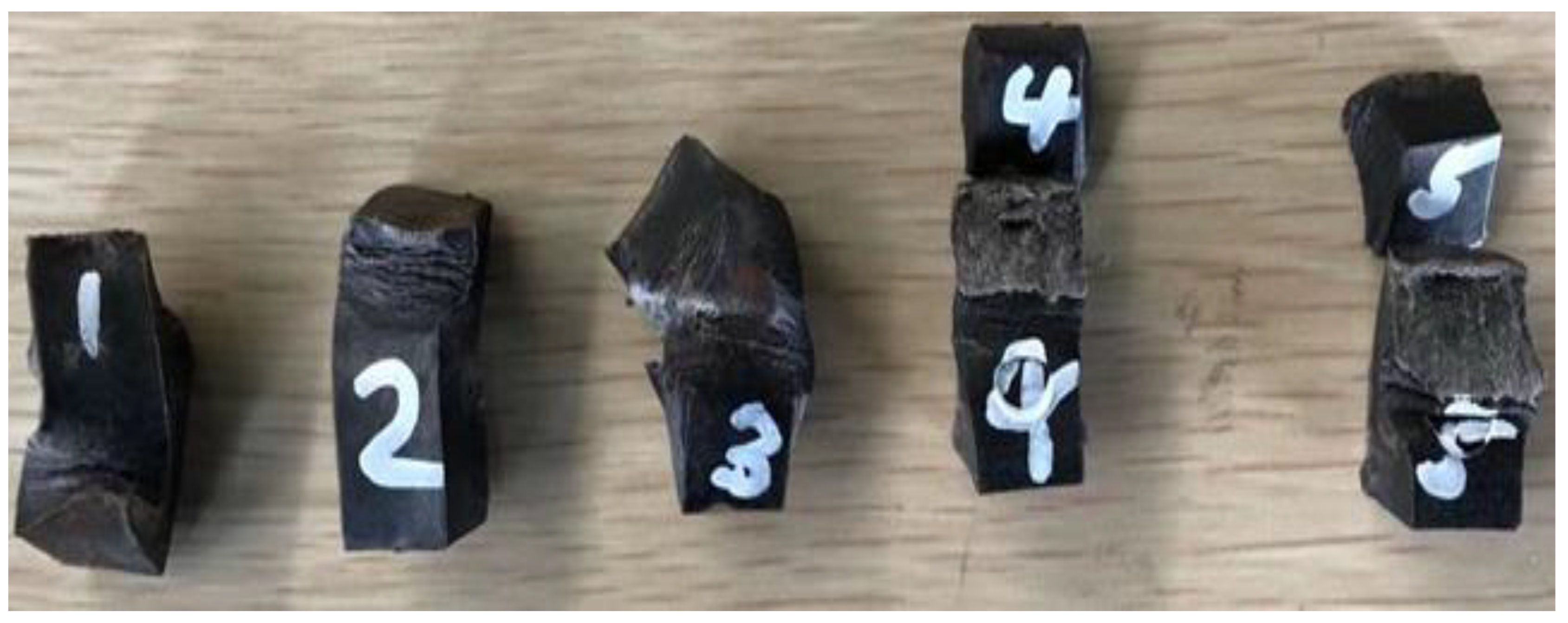
- 3. Impact Resistance Test
2.2.2. Structure of Hanging Basket
- A. Introduction to the structure of the Hanging Basket
- B. The construction of Finite Element Model of the Hanging Basket
- C. Working condition of the Hanging Basket
2.3. Simulation of the Walking Track and the Hanging Basket
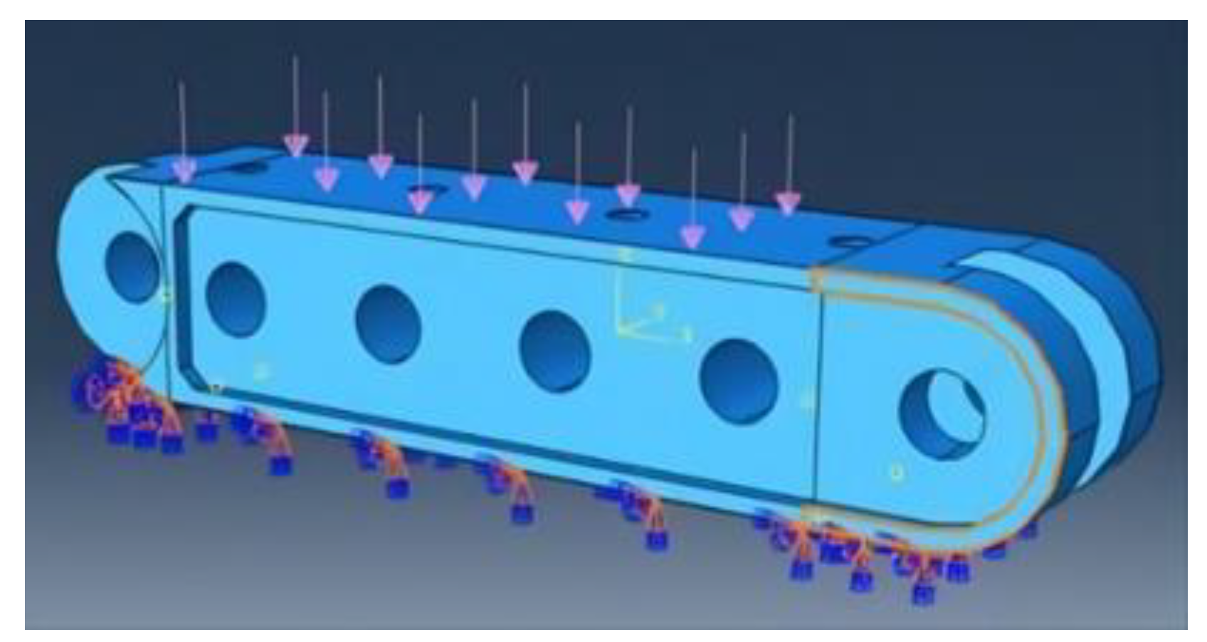
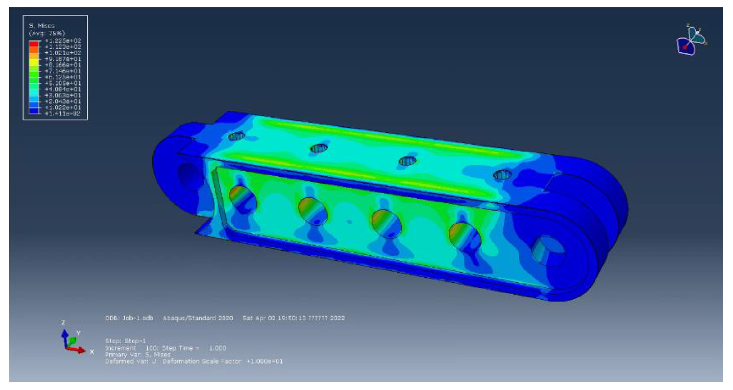
2.3.1. Finite Element Simulation of New Material for Walking Track
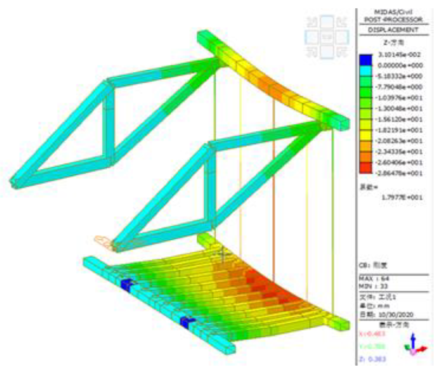
2.3.2. Finite Element Simulation of the Hanging Basket Structure Based on Midas/Civil
- A. Analysis on Mechanical Performance of the Hanging Basket under Condition 1
- 1.
- Main Truss
- 2.
- Front Upper Crossbeam
- 3.
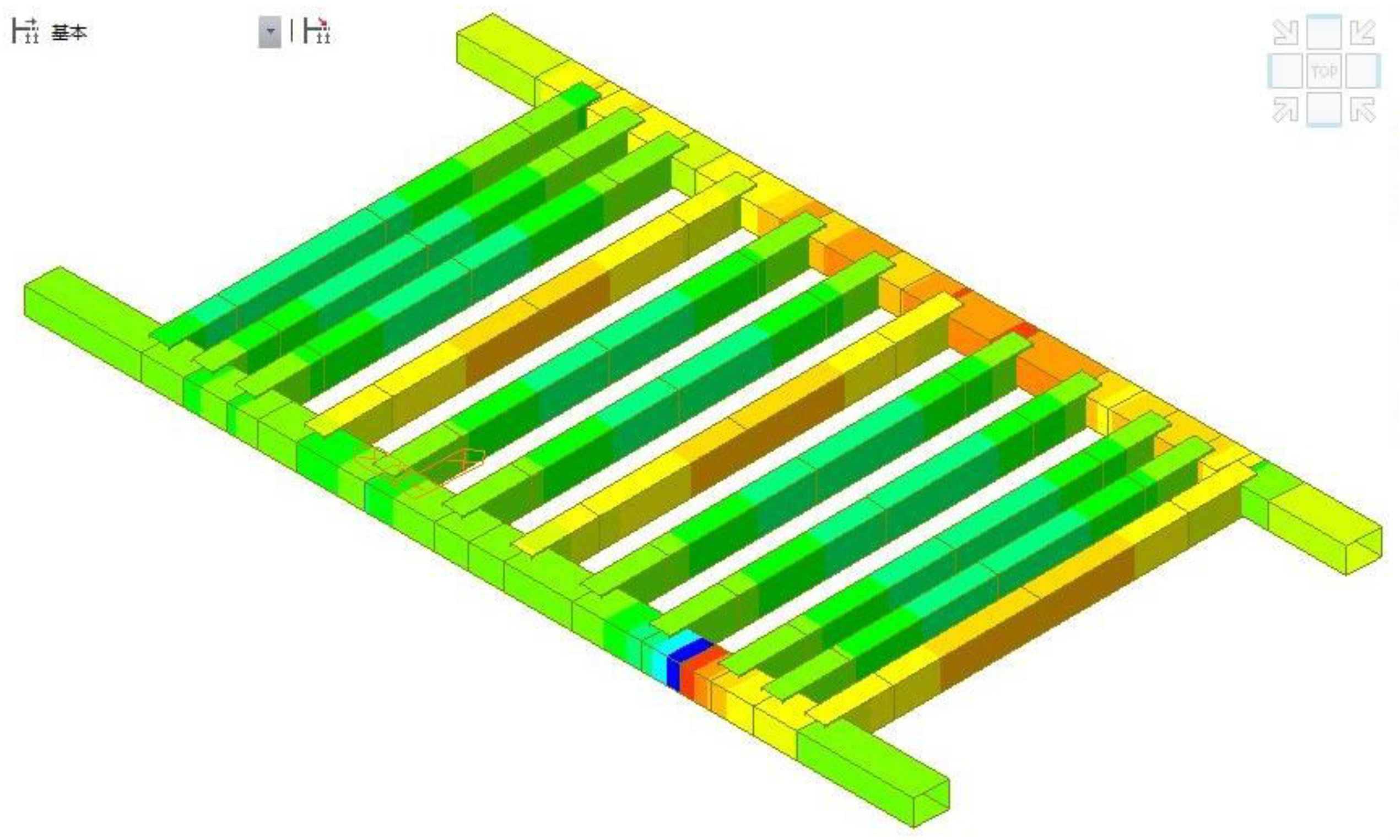
- Bottom Basket
- 4.
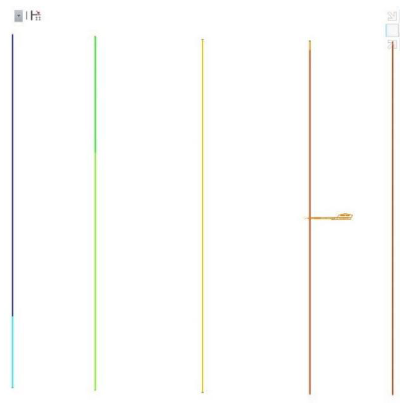
- Hanger Rod
- B. Analysis on Mechanical Performance of the Hanging Basket under Condition 2
- 1. Main truss
- 2. Front upper beam
- 3. Bottom basket
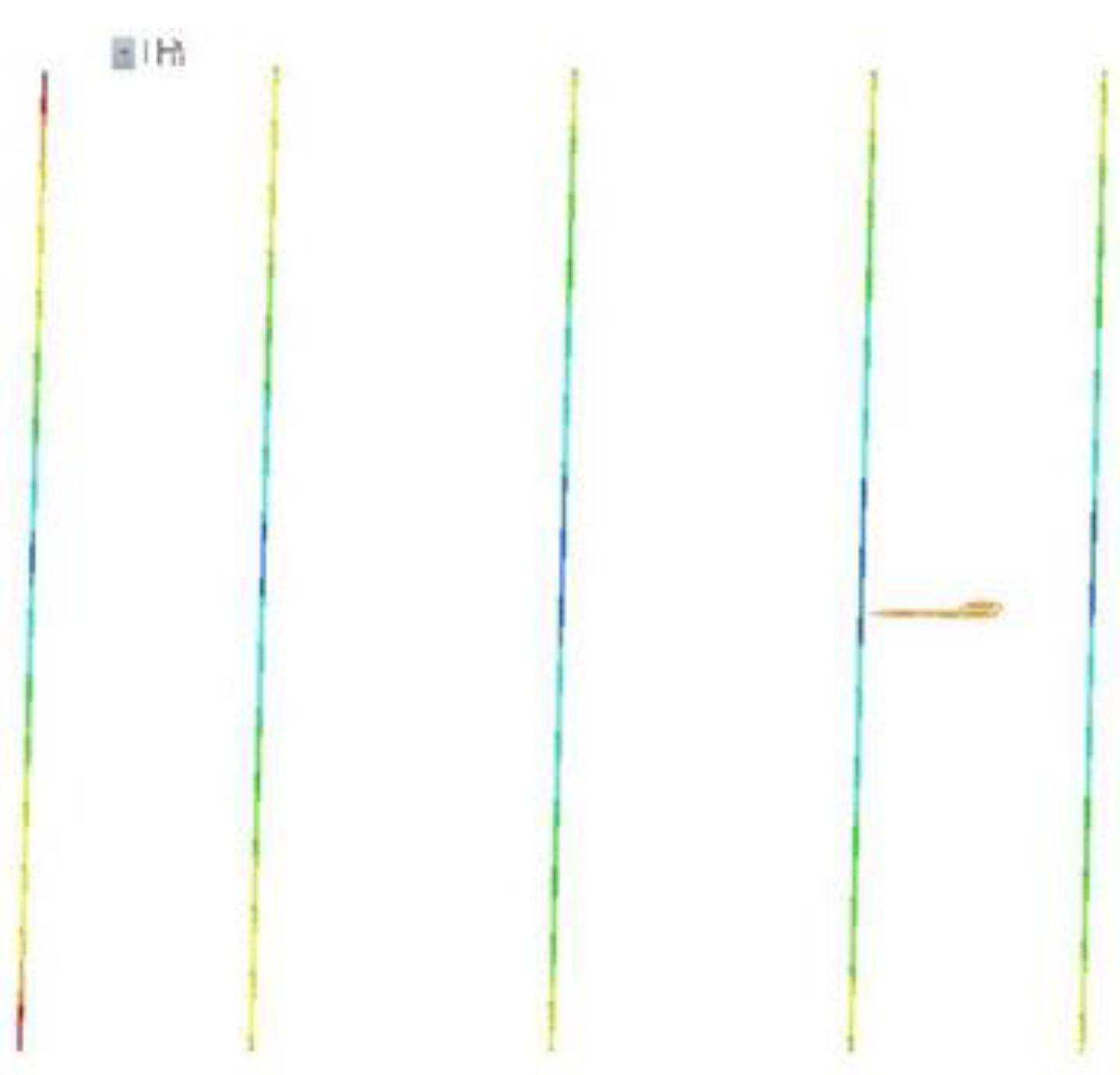
- 4. Suspender
- C. Analysis on Mechanical Performance of the Hanging Basket under Condition 3
2.4. Verification of Key Components and Analysis of the Weak Structures
2.4.1. Member Calculation
- A. Bottom Longitudinal Beam of Web
- B. Bottom Longitudinal Beam under Bottom Plate
2.4.2. Analysis of the Weak Structure
3. Results
3.1. Main Truss Optimization
- A. Front elevation of Main Truss
- B. Main Truss Beam structure
3.2. Optimization of Pouring Section
4. Discussion
Author Contributions
Funding
Data Availability Statement
Conflicts of Interest
Nomenclature
| acU | The impact strength of the specimen(kJ/m2) |
| hcU | The thickness of the specimen (mm) |
| EcU | The energy absorbed by the measured pattern (J) |
| bcU | The width of the specimen (mm) |
| Wd | The wind load |
| The air density(kg/m3) | |
| Vw | The wind speed (m/s) |
| g | The acceleration of gravity |
| MQ | The overturning moment of the hanging basket equipment(N·m) |
| G | The dead weight load(kg) |
| X | The arm of force(mm) |
| q | The load of structure |
| s | The cross-sectional area of structure(m2) |
| The concrete bulk density(t/m3) | |
| k | The load coefficient |
References
- Hyo, G. K. and Je, K.S.: Span ratios in bridges constructed using a balanced cantilever method , The construction and Building Materials, vol.18, no.10, pp.767-779, 2004. [CrossRef]
- Won, J. H., Cho, K. I., Yoon, J. H. et al.,: Innovative key-segment closing method using thermal pre-stressing technique for partially earth-anchored cable-stayed bridges, Advances in Structural Engineering, vol.11, no.5, pp.549–564, 2008. [CrossRef]
- Liu, Z. W., Zhou, J.T., Ma, H. et al.,: Key technology of hanging basket suspension casting construction of yelanghu super large bridge, World bridge, vol.47, no.5, pp.22-26, 2019. [CrossRef]
- Zhao, X. J., He, S. H., Li, Y. et al.,: Simulation analysis of the construction process of front fulcrum han-ging basket of cable-stayed bridge, Journal of Shenzhen University(Science and Engineering Edition),vol.34, no.2, pp. 138-146, 2017. [CrossRef]
- Mashal, M. and Palermo, A.: Low-damage seismic design for accelerated bridge the construction, Journal of Bridge Engineering, vol.24, no.7, Article ID 04019066, 2019. [CrossRef]
- Li, Q. F., Qian, H. J., Pei, J. J. et al.,: Safety risk analysis of bridge rhombic hanging basket construction based on WBS-RBS and rough set theory ,Materials Science and Engineering, vol.780, 2020. [CrossRef]
- Li, L.: Research on key technology of suspension casting the construction of long-span continuous beam bridge, M.S. dissertation, Mar. Elect. China., Anhui University of technology, Huainan City, Anhui Province, China, 2018. [CrossRef]
- Gao, J.: Guyed Traveler Composite of the Central Cable Plane PC Cable-stayed Bridge with Wide Girder Application Technology, M.S. dissertation, Mar. Elect. China., Changan Univ., Xi'an City, Sh-aanxi Province, China, 2016. [CrossRef]
- Chen, L. Y.: Using Midas software to design the main truss of triangular hanging basket for contin-uous beam the construction, National Defense Transportation Engineering and technology, vol.11, no.3,pp.75-77, 2013. [CrossRef]
- An, D. Q.: Research on Structural Analysis and Optimization of Rhombus Hanging Basket for the Up and Down Double Chamber Continuous Rigid-framed Aqueduct, M.S. dissertation, Mar. Elect. China., Zhengzhou Univ., Zhengzhou City, Henan Province, China, doi:CNKI:CDMD:2.1018.088893, 2018.
- Gu, S. F.: Research on Key The construction Technique of Long-span and Broad-width PC Box GirderBridge with Corrugated Steel Webs, Railway The construction Technology, vol.12, no.12, pp.49-53, 2019. [CrossRef]
- He, J., Li, X., Li, X. et al.,: A novel asynchronous-pouring-the construction technology for prestressed concrete box girder bridges with corrugated steel webs, Structures, vol.27, pp.1940-1950, 2020. [CrossRef]
- Zhou, M., Liu, Y. Y. and Wang, K.: New Asynchronous-Pouring Rapid-The construction Method for Long-Span Prestressed Concrete Box Girder Bridges with Corrugated Steel Webs, Journal of The construction Engineering and Management, vol.146, no.2, Article ID 05019021, 2020. [CrossRef]
- Xie, W., Zhao, T. and Tang, J.:Arch first and beam later: arch-rib integral installation the constructiontechnology for large-span tied-arch bridge, Journal of The construction Engineering and Management,vol.143, no.8, Article ID 04017059, 2017. [CrossRef]
- Somaini, D. and Furst, A.: The new bridge over the Saane: modern steel girder for the historic railwayviaduct, Stahlbau, vol.89, no.7, pp.622-627, 2020. [CrossRef]
- Li, R. C., Gui T. J., Cong, W. W. et al.,: Synthesis and performance characterization of fluorin-econtaining silane coupling agent oligomer, Material Guide, vol.35, no.12, pp.2199-2206, 2021. [CrossRef]
- Kosobokov, M. D., Zubkov, M. O. and Levin, V. et al.,: Fluoroalkyl sulfides as photoredox-active coupling reagents for alkene difunctionalization, Chemical Communications, vol.56, no.66, pp.9453 -9456, 2020. [CrossRef]
- Ying, J. Q., Qiu, H. and Zhang, H. J.: Effect of Different Types of Toughening Agent on Properties of Polycarbonate, China Plastics, vol.34, no.7, pp.30-35, 2020. [CrossRef]
- Wolk, A., Rosenthal, M., Weiss, J. et al.,: Graphene oxide as flexibilizer for epoxy amine resins, Progress in Organic Coatings, vol.122, pp.280-289, 2018. [CrossRef]
- Hu, Y., Weng, Z. and Qi, Y.: Self-curing triphenol A-based phthalonitrile resin precursor acts as a flexibilizer and curing agent for phthalonitrile resin, RSC advances, vol.8, no.57, pp.32899-32908, 2018. [CrossRef]
- Wu, X., Wu, T. T., Chen, W. Z. et al.,: Analysis of height difference between three trusses of a steel truss bridge during incremental launching, Stahlbau, vol.87, no.9, pp.910-922, 2018. [CrossRef]
- Zhou, X. H., Qin, F. J. and Di, J.: Continuity analysis method of plate-truss combined stiffening beam based on energy principle, Journal of China Highway, vol.27, no.6, pp.34-43, 2014. [CrossRef]

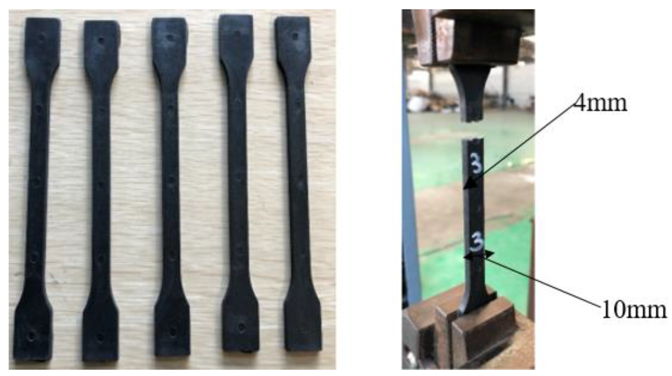

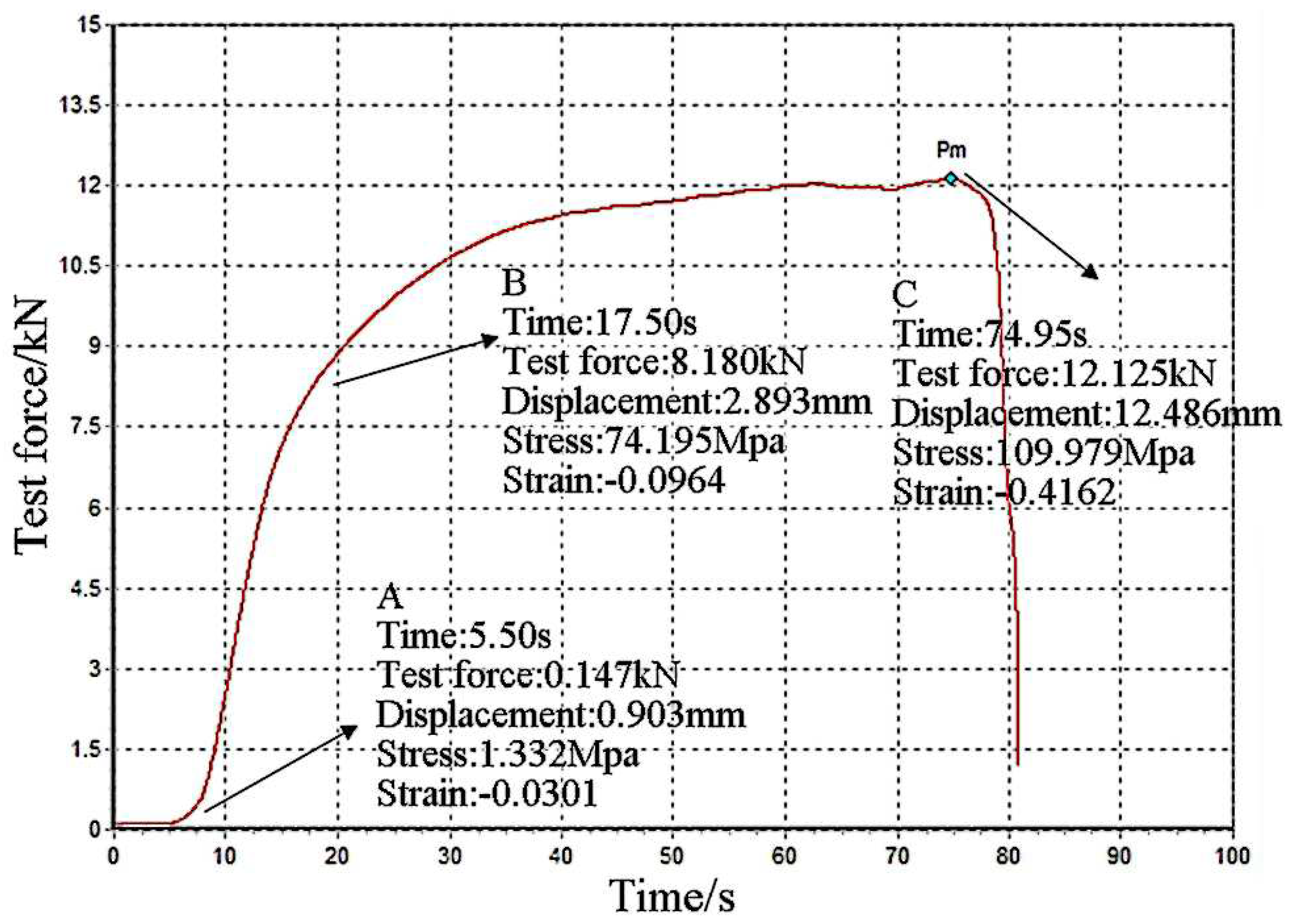
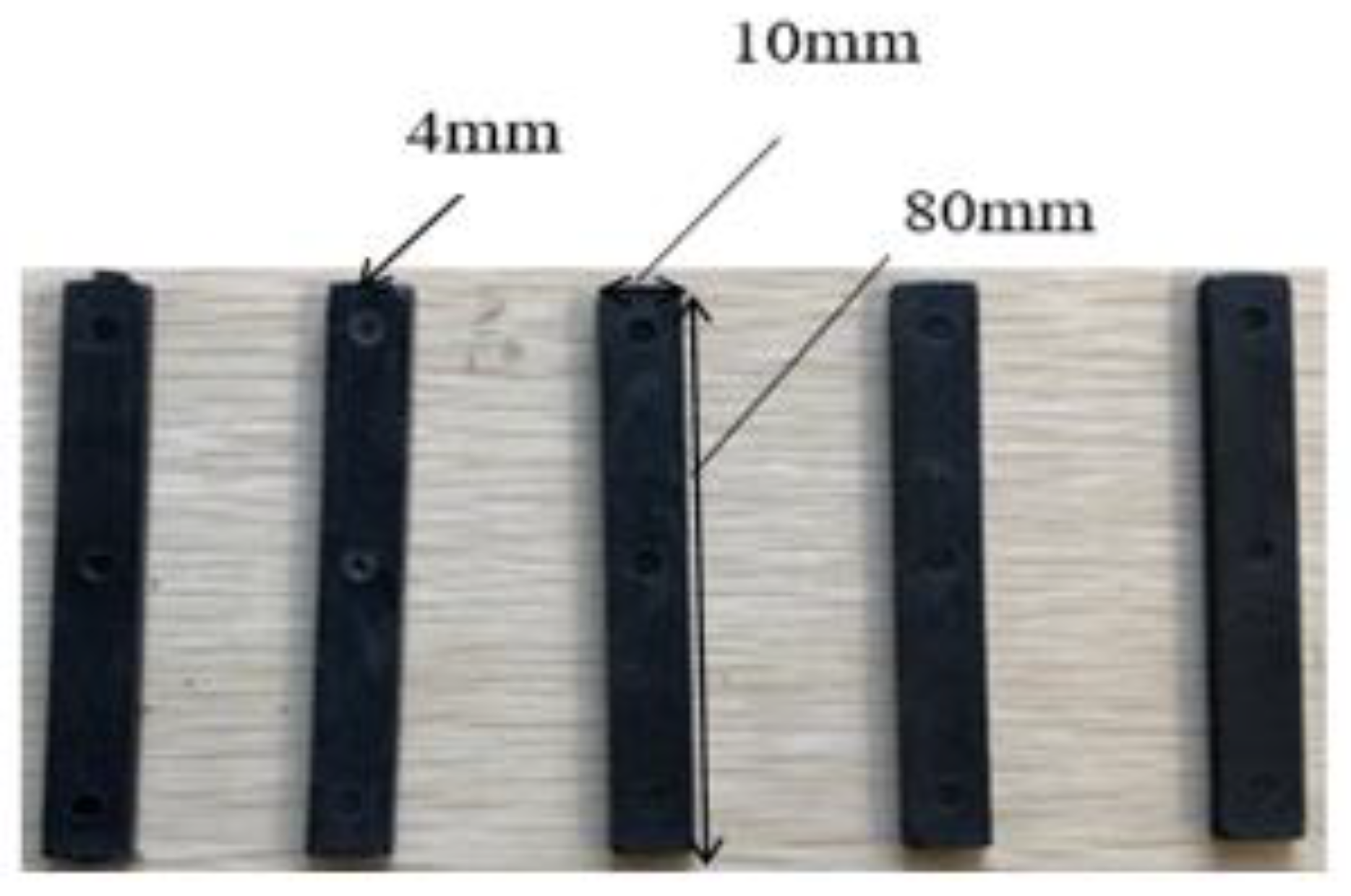
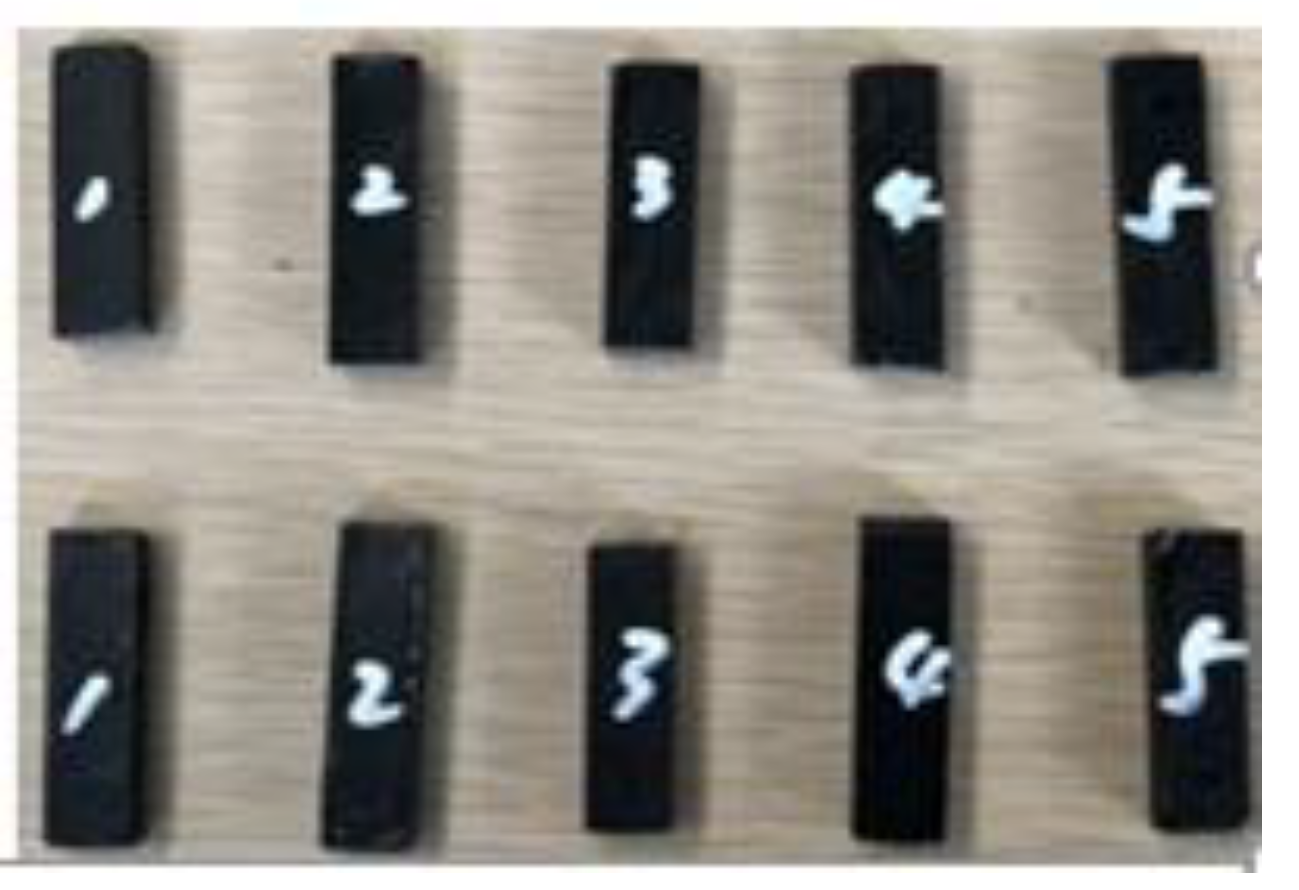
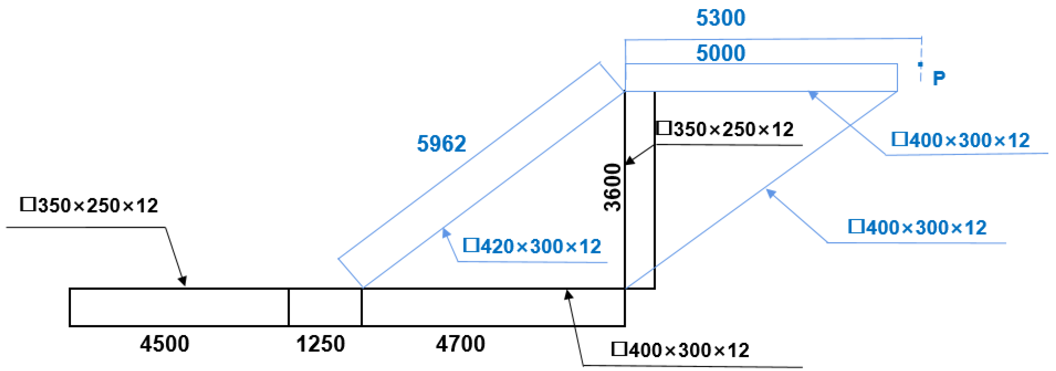
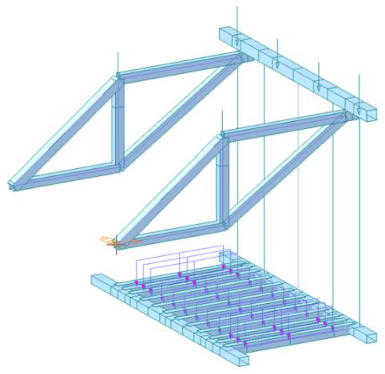


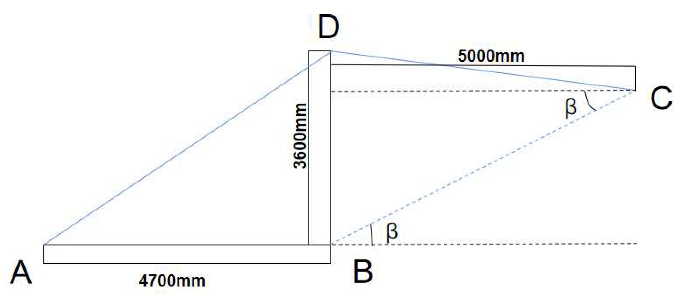

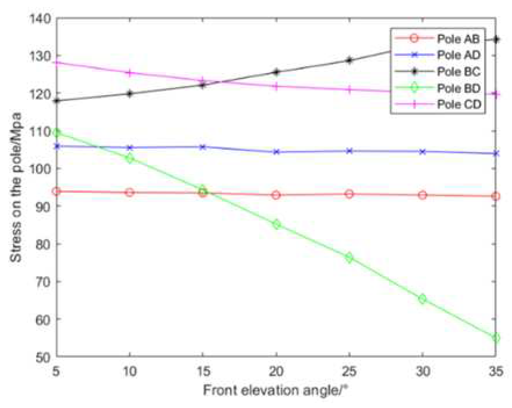
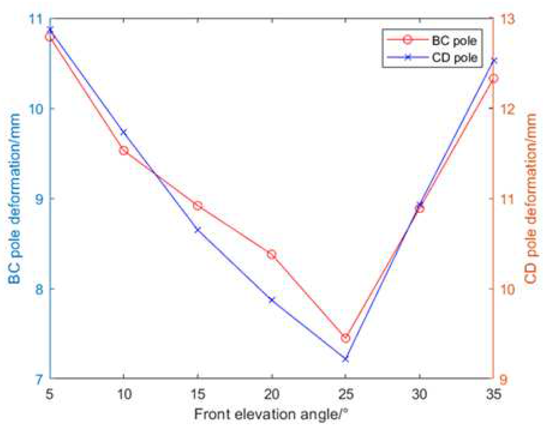
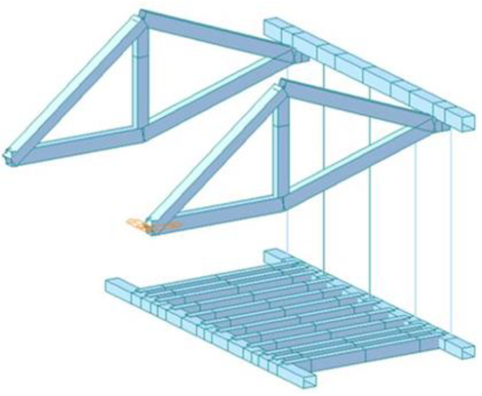
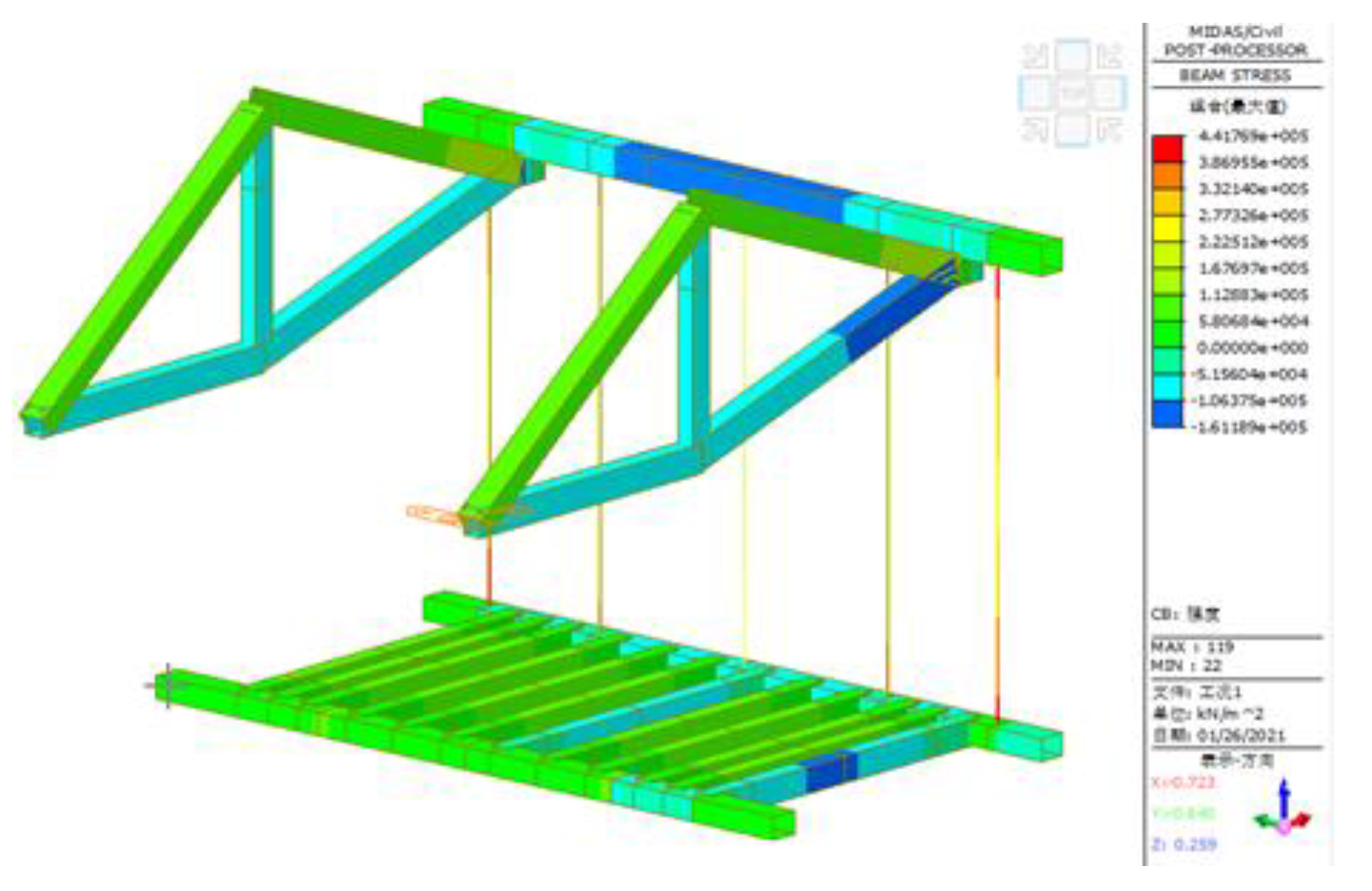
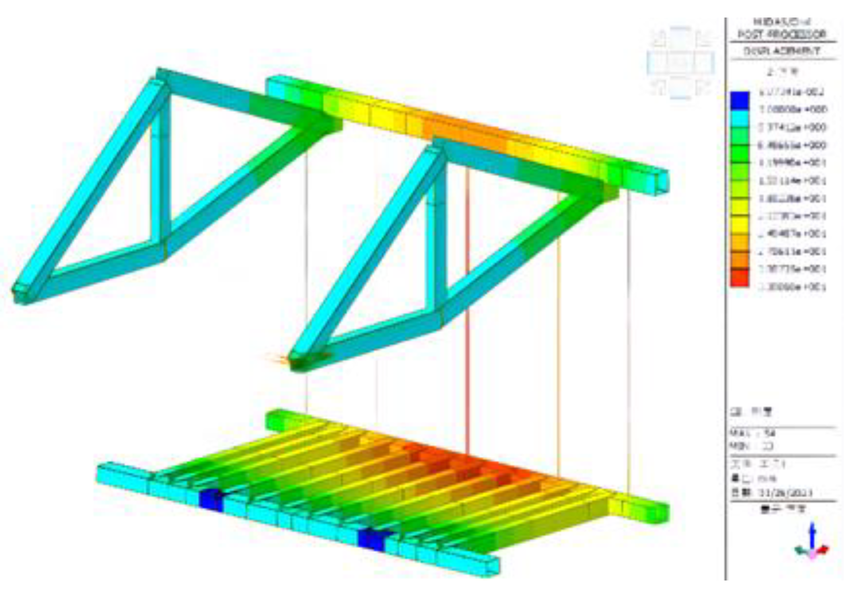
| Experimental instrument | Electronic universal testing machine |
| Experimental temperature | 20℃ |
| Stretching speed | 50mm/min |
| Test repetition times | 5 |
| Number of test samples | 5 |
| Experimental instrument | Electronic universal testing machine |
| Experimental temperature | 20℃ |
| Compression speed | 10mm/min |
| Test repetition times | 5 |
| Number of test samples | 5 |
| Experimental instrument | Impact testing machine |
| Experimental temperature | 20℃ |
| Pendulum energy | 7.5J |
| Impact speed | 3.8m/s |
| Test repetition times | 5 |
| Number of test samples | 5 |
| Experiment | Elevation [°] |
Air attack angle[°] | Impact angle[°] | Absorbed energy[J] |
Impact strength [kJ/m2] |
|---|---|---|---|---|---|
| 1 | 160 | 158.40 | 101.92 | 2.797 | 69.92 |
| 2 | 160 | 158.40 | 103.63 | 2.685 | 67.12 |
| 3 | 160 | 158.40 | 107.23 | 2.452 | 61.30 |
| 4 | 160 | 158.40 | 98.55 | 3.022 | 75.55 |
| 5 | 160 | 158.40 | 105.36 | 2.575 | 64.37 |
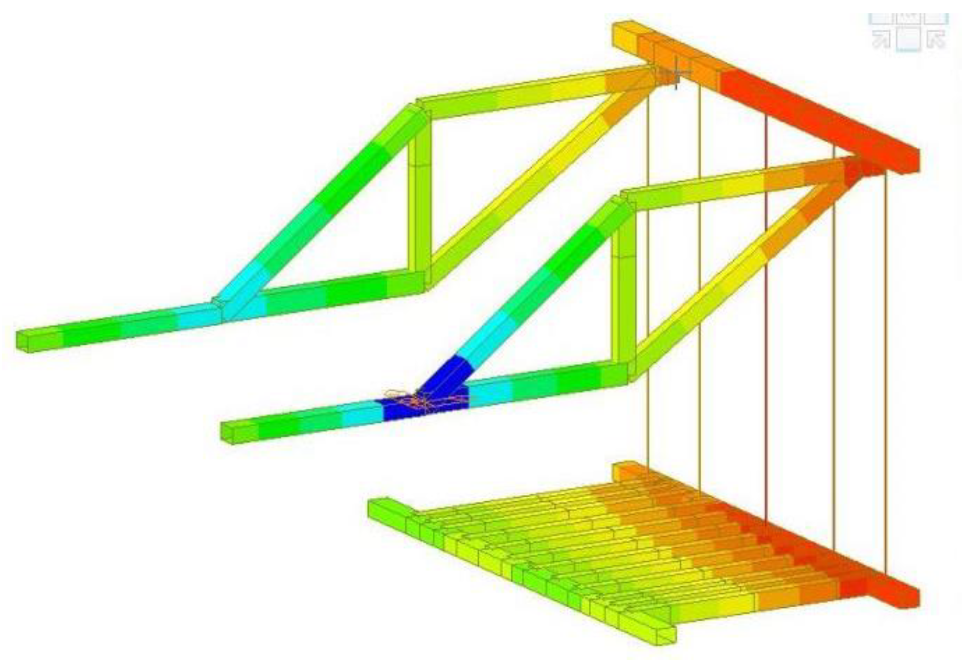
| Member name | Max stress [Mpa] | Max vertical distortion [mm] | Allowable stress [Mpa] | Allowable distortion [mm] |
|---|---|---|---|---|
| AB | 92.6 | 0.25 | 175 | 11.75 |
| CD | 149.7 | 12.53 | 175 | 13.25 |
| BD | 55.0 | 0.41 | 175 | 9.00 |
| AD | 103.9 | 0.60 | 175 | 14.91 |
| BC | 134.2 | 10.33 | 175 | 15.25 |
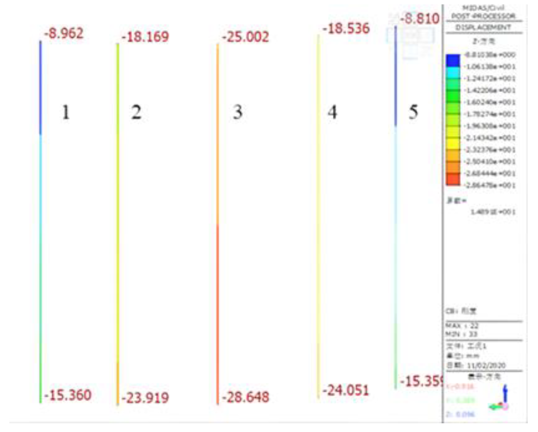
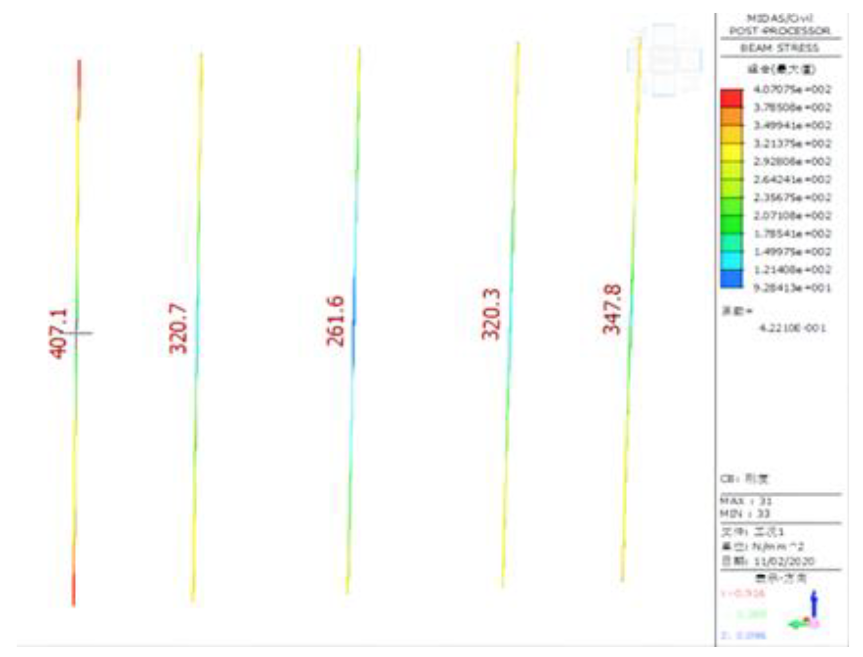
| Suspender name | Max distortion [mm] | Max stress [Mpa] | Allowable stress[Mpa] |
|---|---|---|---|
| 1 | 2.83 | 470.1 | 650 |
| 2 | 11.39 | 320.7 | 650 |
| 3 | 16.11 | 261.6 | 650 |
| 4 | 11.52 | 320.3 | 650 |
| 5 | 2.83 | 347.8 | 650 |
| Member name | Maximum stress | Maximum vertical distortion/mm | Allowable stress/Mpa | Allowable distortion/mm |
|---|---|---|---|---|
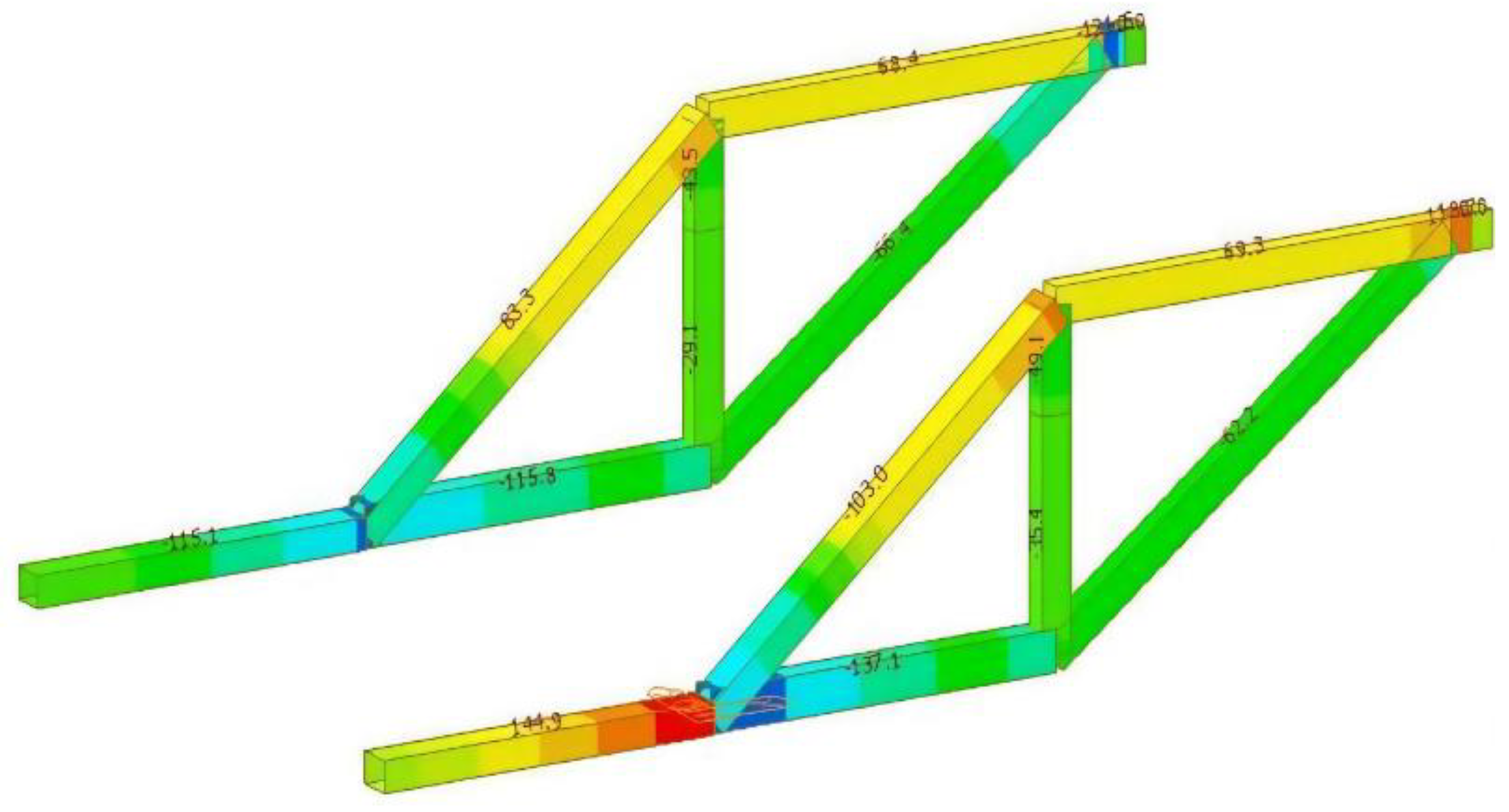
| AB | 137.1 | 16.9 | 175 | 11.75 |
| CD | 118.7 | 9.9 | 175 | 13.25 |
| BD | 49.1 | 0.12 | 175 | 9.00 |
| AD | 103.0 | 7.0 | 175 | 14.91 |
| BC | 62.2 | 9.7 | 175 | 15.25 |
| AE | 114.9 | 7.1 | 175 | 11.25 |
| Suspender name | Maximum distortion/mm | Maximum stress/Mpa | Allowable stress/Mpa |
|---|---|---|---|
| 1 | 17.13 | 295.4 | 650 |
| 2 | 19.37 | 218.8 | 650 |
| 3 | 21.76 | 260.1 | 650 |
| 4 | 22.94 | 162.3 | 650 |
| 5 | 23.18 | 167.9 | 650 |
| Member | Finite element analysis results | Allowable value | Performance redundancy | ||||
| Stress [Mpa] |
Distortion [mm] |
Stress [Mpa] | Distortion [mm] | Stress [%] |
Distortion [%] | ||
| Main Trusses | AB | 92.6 | 0.21 | 175 | 11.75 | 47.09 | 98.21 |
| AD | 103.9 | 0.60 | 175 | 14.91 | 40.63 | 95.98 | |
| BC | 134.2 | 10.33 | 175 | 15.25 | 23.31 | 32.26 | |
| BD | 55.0 | 0.41 | 175 | 9.00 | 68.57 | 95.44 | |
| CD | 119.7 | 12.53 | 175 | 13.25 | 31.60 | 5.43 | |
| Front upper crossbeam | 113.8 | 12.47 | 175 | 18.13 | 34.97 | 31.22 | |
| Bottom longitudinal beam | Under the Web | 71.32 | 9.05 | 175 | 15.25 | 59.25 | 40.66 |
| Under the floor | 57.99 | 13.67 | 175 | 15.25 | 66.86 | 10.36 | |
| Lower cross beam |
Front lower beam | 52.93 | 16.12 | 175 | 18.00 | 69.75 | 10.44 |
| Lower rear beam | 48.59 | 9.80 | 175 | 18.00 | 72.23 | 45.56 | |
| Front elevation angle | 35° | 30° | 25° | 20° | 15° | 10° | 5° |
| BC+BD Pole length[m] |
11.161 | 10.824 | 10.675 | 10.628 | 10.664 | 10.768 | 10.935 |
| BC+BD Rod steel amount[kg] |
1421.5 | 1378.5 | 1359.6 | 1353.6 | 1358.1 | 1371.4 | 1392.7 |
| Original dimension of pole /mm | Optimized pole size /mm | Reduced steel consumption /kg | |
|---|---|---|---|
| AB pole | □400×300×12mm | □380×280×12mm | 3.744 |
| AD pole | □420×300×12mm | □400×280×12mm | 7.488 |
| BD pole | □350×250×12mm | □330×230×12mm | 3.744 |
Disclaimer/Publisher’s Note: The statements, opinions and data contained in all publications are solely those of the individual author(s) and contributor(s) and not of MDPI and/or the editor(s). MDPI and/or the editor(s) disclaim responsibility for any injury to people or property resulting from any ideas, methods, instructions or products referred to in the content. |
© 2023 by the authors. Licensee MDPI, Basel, Switzerland. This article is an open access article distributed under the terms and conditions of the Creative Commons Attribution (CC BY) license (http://creativecommons.org/licenses/by/4.0/).


