1. Introduction
Structural walls are frequently incorporated into the design of earthquake and wind-resistant reinforced concrete structures. Their presence is vital in minimizing inter-story drifts by providing rigidity to the building system under horizontal loads. However, the efficient transfer of loads between these wall elements is crucial for achieving coupled wall action, thereby further enhancing the structure’s lateral stiffness and ductility properties. This is where coupling beams come into play.
Coupling beams serve as critical components that facilitate load transfer between structural walls. Their primary function is to ensure that the coupled wall system functions cohesively, with the ability to effectively distribute forces and absorb energies during seismic events. Consequently, the load and deformation capacities of coupling beams significantly impact the energy dissipation behavior of the entire coupled wall system.
In summary, coupling beams play a crucial role in connecting structural walls, promoting coupled wall action, and improving the overall lateral stiffness and ductility characteristics of earthquake and wind-resistant buildings. By prioritizing ductility in their design and detailing, coupling beams can effectively contribute to the energy dissipation behavior of coupled wall systems, ultimately enhancing the safety and resilience of these structures during seismic events.
Achieving ductile behavior in coupling beams with low aspect ratios (span to depth) is commonly accomplished through the implementation of diagonal reinforcement bundles, a detailing technique initially proposed by Paulay and Binney [
1]. Subsequent tests have consistently validated that coupling beams with diagonal reinforcement exhibit significantly more ductile behavior compared to conventionally reinforced beams using longitudinal and transverse reinforcement details. This finding is particularly pronounced in the case of short beams with aspect ratios below 2, as demonstrated in studies conducted by Galano and Vignoli [
2], Gonzalez [
3], Wallace [
4], and Han et al. [
5].
In the research conducted by Eser et. al. [
6], a series of tests were carried out on coupling beams designed with consideration of various detailing layouts. The characteristics of these specimens were thoroughly described in the dedicated specimens’ section. The test results demonstrated that certain detailing variations, such as reducing stirrups, using regional stirrups, omitting transverse reinforcement in the middle span, restraining axial elongation, and anchoring the longitudinal reinforcements into the shear walls, had a significant impact on the coupling beams’ performance. The study emphasized the importance of adhering to especially sufficient confinement conditions in the design of coupling beams to ensure their proper functionality and performance during dynamic events such as earthquakes and winds.
In previous studies, the approach often involved strengthening undamaged specimens before testing. However, the present study adopted a different perspective by focusing on strengthening coupling beams that had already experienced damage. This choice was motivated by the practical scenarios commonly encountered in real-life building structures, where damage and collapse mechanisms may occur, necessitating immediate retrofitting measures.
The literature offers limited studies on the strengthening of coupling beams. Riyazi et al. [
7] conducted tests on 6 specimens and strengthened 2 of them by strip-wrapping with CFRP after sustaining damage. The results indicated an increase in shear strength with strip wrapping, but there was a decrease in stiffness.
In another study, Honarparast, El-Saikaly, and Chaallal [
8] investigated the reinforcement of coupling beams with CFRP using 2 samples. The first sample, serving as a control, was tested without any reinforcement. The second sample was tested with diagonal CFRP placement on both sides. The strengthened sample exhibited improved strength, energy dissipation capacity, hysteretic behavior, and ductility compared to the control sample.
Additionally, Xian et al. [
9] studied 4 specimens, one of which was tested without any reinforcement as a control. The remaining three specimens underwent U-type CFRP wrapping. Among them, one had only U-type wrapping, while the other received diagonal CFRP placement in addition to the U-type wrapping. An anchor was added to the last specimen after U-type and diagonal wrapping. The strengthening process enhanced the deformability, strength, ductility, and energy dissipation capacity of the specimens, with the sample featuring diagonal CFRP showing the best performance. Furthermore, the addition of anchoring to the strengthening method extended the deterioration time of CFRP.
Overall, the studies mentioned above demonstrate the effectiveness of CFRP (Carbon Fiber Reinforced Polymer) strengthening in enhancing the performance of undamaged coupling beams. The findings highlight the potential of using CFRP materials as a viable solution for retrofitting and improving the seismic behavior of these critical undamaged structural elements.
Building upon the insights gained from the coupling beam studies, this article focuses on examining the seismic behavior of damaged coupling beams strengthening with GFRP (Glass Fiber Reinforced Polymer) wrapping. Additionally, the article delves into the subsequent retrofitting of test specimens, considering the implications of the findings from the coupling beam studies. By investigating the performance of damaged coupling beams and the effectiveness of GFRP wrapping as an urgent strengthening technique, the research aims to contribute valuable knowledge and practical guidelines for strengthening coupling beams in real-life structural applications. Ultimately, the study seeks to enhance our understanding of seismic response mechanisms in diagonally reinforced coupling beams and advance the development of effective and rapid strengthening strategies to enhance the seismic resilience of high-rise buildings constructed with structural walls.
Given the significance of coupling beams as vital structural elements, they are typically designed with the foresight of potential damage. However, the aftermath of major earthquakes necessitates immediate remedial measures. Surprisingly, there is a lack of existing studies that address emergency response measures for such critical scenarios in the literature. Our research is primarily motivated by the urgent need to address such critical retrofitting scenarios. By focusing on the retrofitting of coupling beams that have already experienced damage, our study aims to explore effective and timely measures to enhance their structural integrity and resilience. By examining and developing retrofitting techniques for coupling beams facing potential collapse, we hope to contribute valuable insights and practical solutions for emergency response and the improvement of seismic performance in high-rise buildings with structural walls. The research seeks to address the challenges posed by the aftermath of severe seismic events, thereby enhancing the safety and stability of these structures during future earthquakes or other extreme conditions.
2. Experimental Investigation
The tested coupling beams in this study were scaled down to a 1:2 scale, making them suitable for use in mid-height buildings and high-rise structures. The aspect ratio of these prototype coupling beams was chosen as 2, representing the ratio of span to section depth. The cross-sectional dimensions of the coupling beams measure 600 mm x 900 mm [23.62 in x 35.43 in]. For diagonal reinforcement, 2 bundles were planned, each consisting of 8-Φ32 bars.
The shear strength of the prototype coupling beams was determined based on the provisions specified in the TSDC -2018 (Turkish Seismic Design Code) [
10]. The material properties used for the calculations are as follows: the yield strength of longitudinal reinforcement (fyd) is 420 MPa (60915 psi), and the compressive strength of concrete (fc’) is 40 MPa (5800 psi). These parameters are critical in determining the structural capacity and performance of the coupling beams during seismic loading.
2.1. Specimens
The tests were conducted using prototype beams produced at a 1:2 scale due to limitations in the capacity of the test equipment. In order to ensure similarity between the prototype beams and the full-scale beams, similarity theory requirements were meticulously met. To achieve this, various parameters such as the volumetric stirrup ratio, reinforcement spacing, and diameter in each prototype tie beam were carefully adjusted to be similar to those in the full-scale beams.
Consequently, the test specimens were constructed with dimensions of 300 mm x 450 mm (11.81 in x 17.72 in). The diagonal reinforcements used in the specimens were selected as 4-Φ22 (4-0.866 in), aligning with the scaling requirements to maintain similarity between the prototype and full-scale coupling beams.
In this study, a total of 3 prototype coupling beams were designed, each featuring diagonal reinforcement bundles. Among them, one beam was designed in accordance with the provisions outlined in ACI 318 [
11], Eurocode [
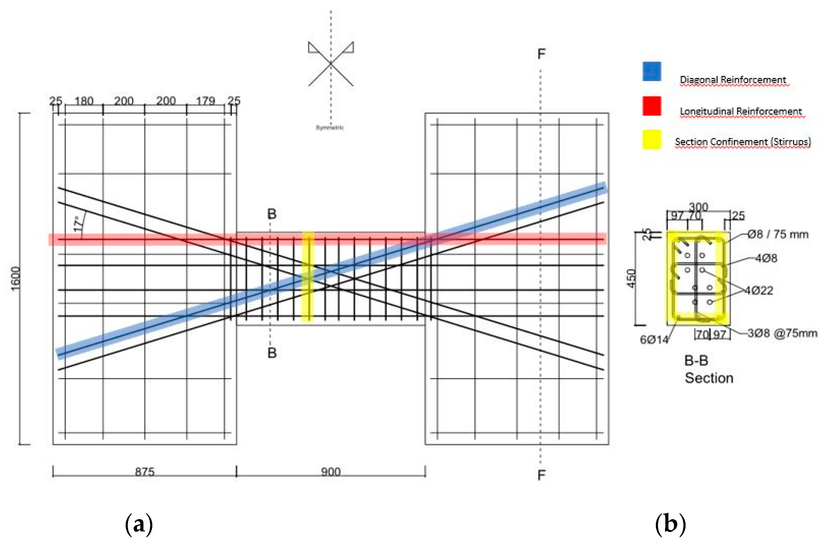
12], and TSDC (Turkish Seismic Design Code). Notably, TSDC requires diagonal bundles to extend into the curtains up to 1.5 times the development length, which was carefully adhered to in the test samples. The longitudinal reinforcement was placed with the required anchorage length, aligning precisely with TSDC specifications. These beams were labeled with the prefix “CB2” to indicate their aspect ratio of 2, where “CB” stands for “Confined Bundle.”
For the other two samples, a more flexible approach was taken in the reinforcement detailing, differing from the strict adherence to regulations. In line with the study’s purpose, a novel and safer reinforcement detailing process was explored by stretching the stirrup wrapping. This design flexibility was incorporated to investigate the effectiveness of alternative reinforcement configurations in enhancing the seismic performance of the coupling beams.
In the first example, we designed a coupling beam without wrapping stirrups around the diagonal bundles, and we named it CB2-UCB, where “UCB” stands for “Unconfined Bundle.” This sample adheres to the detailing described in the regulations for coupling beams with unwrapped diagonal bundles.
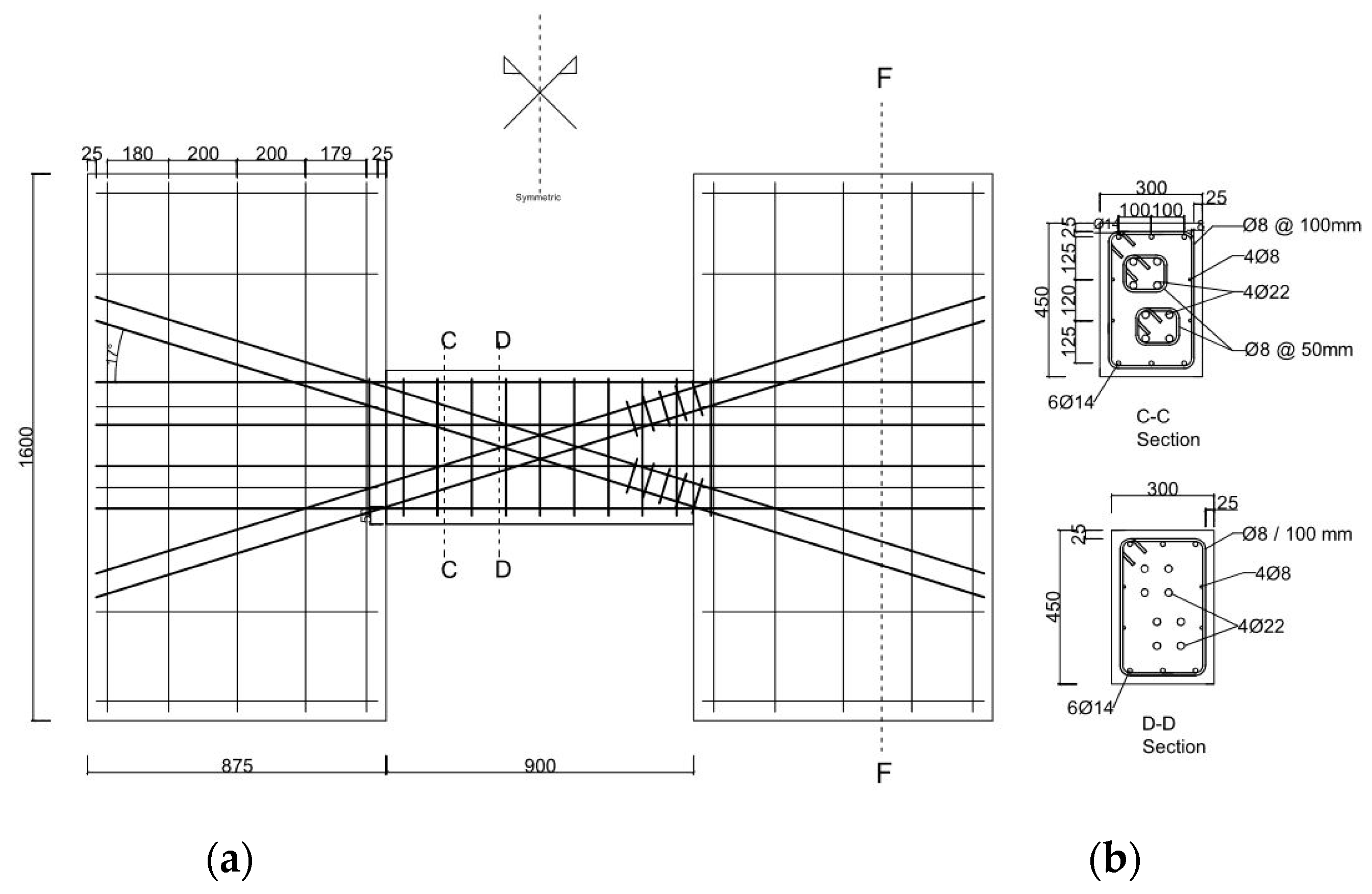
In the second example, the diagonal bundles were constructed with a partial wrapping application, which differs from the standard regulations. The wrapping process was specifically applied to the tightening regions of the tie beams, located at a distance of d/2 from the effective beam depth (where d is the depth of the beam). We designated this sample as CB2-PCB, with “PCB” representing “Partially Confined Bundle.”
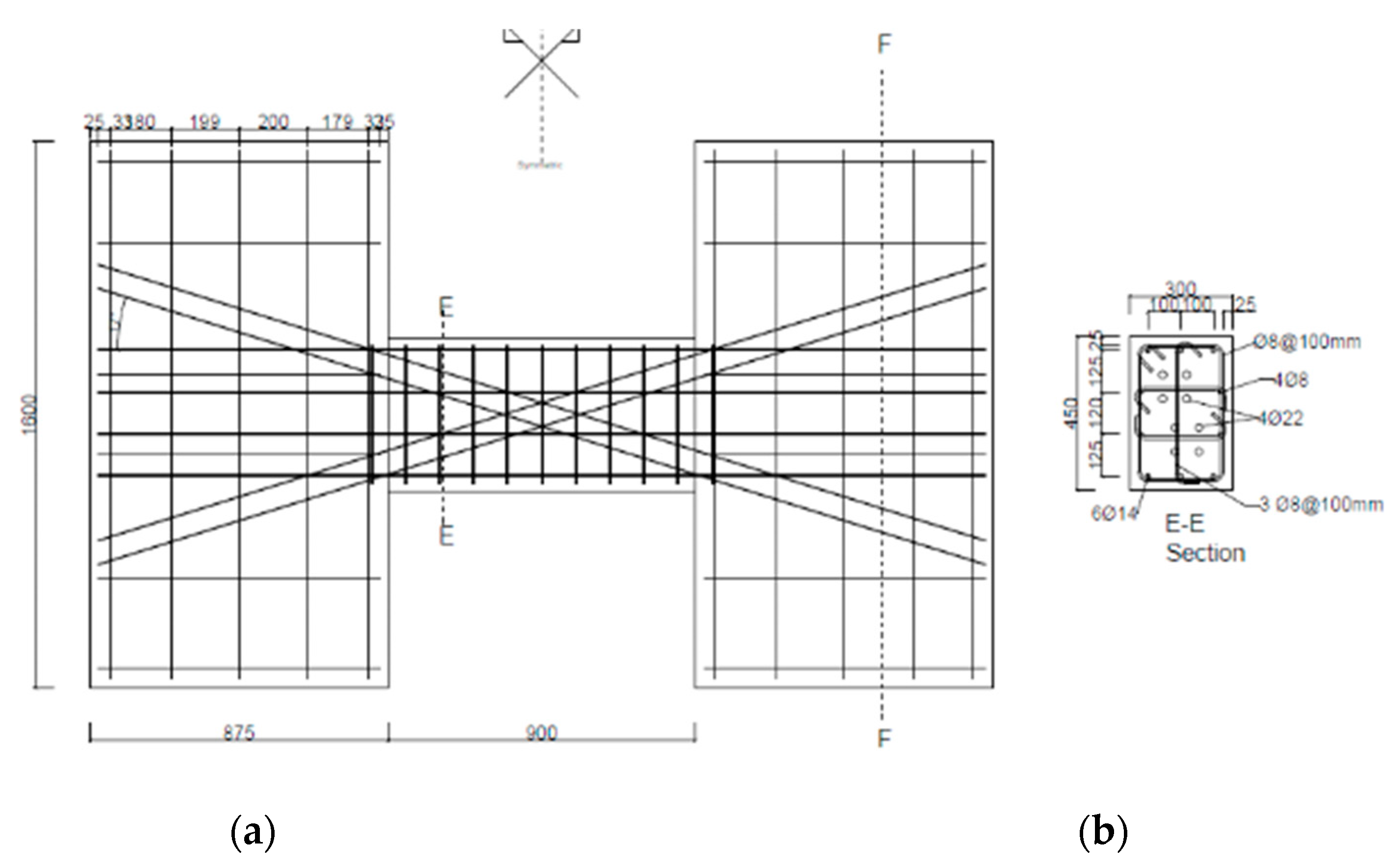
In the third example, we completed the construction of the diagonal bundles without any wrapping around them. Generally, ACI 318, Eurocode, and TSDC recommend increased stirrup wrapping for unwrapped diagonal bundles. However, for this study, we chose to stretch the wrapping application while adhering to the regulations. We named this sample CB2-RCR, with “RCR” indicating “Reduced Section Confinement Ratio.”
In CB2-RCR, the reduction in the wrapping ratio implies that the tie beam is fully wrapped, but with a decreased stirrup ratio, while the diagonal bundles remain unwrapped. This unique configuration allowed us to assess the effectiveness of reducing the stirrup confinement on the seismic behavior of the coupling beam, providing valuable insights for potential retrofitting strategies.
The geometry and reinforcement detailing of the tested specimens are summarized in
Figure 1,
Figure 2 and
Figure 3 below.
2.2. Materials
Material samples were carefully obtained to determine the mechanical properties of both the reinforcement and concrete used in the study. Concrete samples were subjected to examinations at 7-day, 28-day, and test-day intervals. Likewise, the yield and maximum tensile strengths of the reinforcements were thoroughly tested.
For the CB2-UCB specimen, the concrete strengths at 7-day, 28-day, and test-day evaluations were measured as 31.9 MPa, 40 MPa, and 50.5 MPa (46.2 ksi, 58.0 ksi, and 73.2 ksi), respectively. Similarly, the concrete strengths of the CB2-PCB sample were determined as 35.7 MPa, 40.2 MPa, and 51.9 MPa (51.8 ksi, 58.4 ksi, and 75.3 ksi) at the corresponding time intervals.
Regarding the last example, CB2-RCR, the concrete strengths at 7-day, 28-day, and test-day assessments were recorded as 41.4 MPa, 48.1 MPa, and 51.4 MPa (60.1 ksi, 69.7 ksi, and 74.5 ksi), respectively.
Furthermore, for the CB2-UCB example, the yield strength of the Φ22 diameter reinforcement was measured as 466 MPa (67.6 ksi), and the maximum strength was observed to be 570 MPa (82.7 ksi). In the case of the Φ14 diameter reinforcement used in the CB2-PCB sample, the yield strength was found to be 464 MPa (67.3 ksi), while the maximum strength reached 579 MPa (83.98 ksi). Finally, for the Φ8 diameter reinforcement employed in the CB2-RCR sample, the yield strength was determined to be 461 MPa (66.86 ksi), and the maximum strength was measured at 592 MPa (85.86 ksi).
Tyfo SEH-25A FRP [
13] material was used to strengthen the damaged samples. Typical test results of the manufacturer for material properties are listed in
Table 1. Before the reinforcement process, Teknorep 300 ex repair mortar [
14] and Mapewrap 31 T/A epoxy [
15] were used for the damaged samples during preparation. Manufacturer typical test results for material properties of these products are shared in
Table 2 and
Table 3a,3b,3c.
Table 1.
Typical dry fiber properties.
Table 1.
Typical dry fiber properties.
| Property |
Typical Test Value |
| Tensile Strength |
3.24 Gpa (470,000 psi) |
| Tensile Modulus |
72.4 Gpa (10.5 x 10⁶ psi) |
| Ultimate Elongation |
4.5% |
| Density |
2.55 g/cm2 (0.092 lbs/in2
|
| Weight per sq. yd. |
505 g/cm2 14.9 oz |
Table 2.
Epoxy material properties.
Table 2.
Epoxy material properties.
| Property |
ASTM Method |
Typical Test Value |
| Post Cure (24 hours) |
ASTM D-4065 |
85ºC (180ºF) |
| Tensile Strength |
ASTM D-638 Type 1 |
72.4 Mpa (10,500 psi) |
| Tensile Modulus |
ASTM D-638 Type 1 |
3.18 Gpa (461,000 psi) |
| Elongation Percent |
ASTM D-638 Type 1 |
5.0% |
| Flexural Strength |
ASTM D-790 |
123.4 Mpa (173900 psi) |
| Flexural Modulus |
ASTM D-790 |
3.12 Gpa (452,000 psi) |
Table 3.
a. Repair mortar properties.
Table 3.
a. Repair mortar properties.
| Color |
Application Thickness |
Compression Strength |
| Grey |
5-50 mm |
55MPa (28 Days) |
Table 3.
b. Repair mortar properties.
Table 3.
b. Repair mortar properties.
| Tensile Strength in Bending |
Usage Period |
Floor Temperature to be Applied |
| 9 MPa (28 Gays) |
30 min. |
+5 - (+)30ºC |
Table 3.
c. Repair mortar properties.
Table 3.
c. Repair mortar properties.
| Dry Powder Density |
Wet Mortar Density |
Consumption for 1 cm thickness |
| 1.55 kg/lt |
2.10 kg/lt |
21 kg/m2
|
2.3. Test Setup
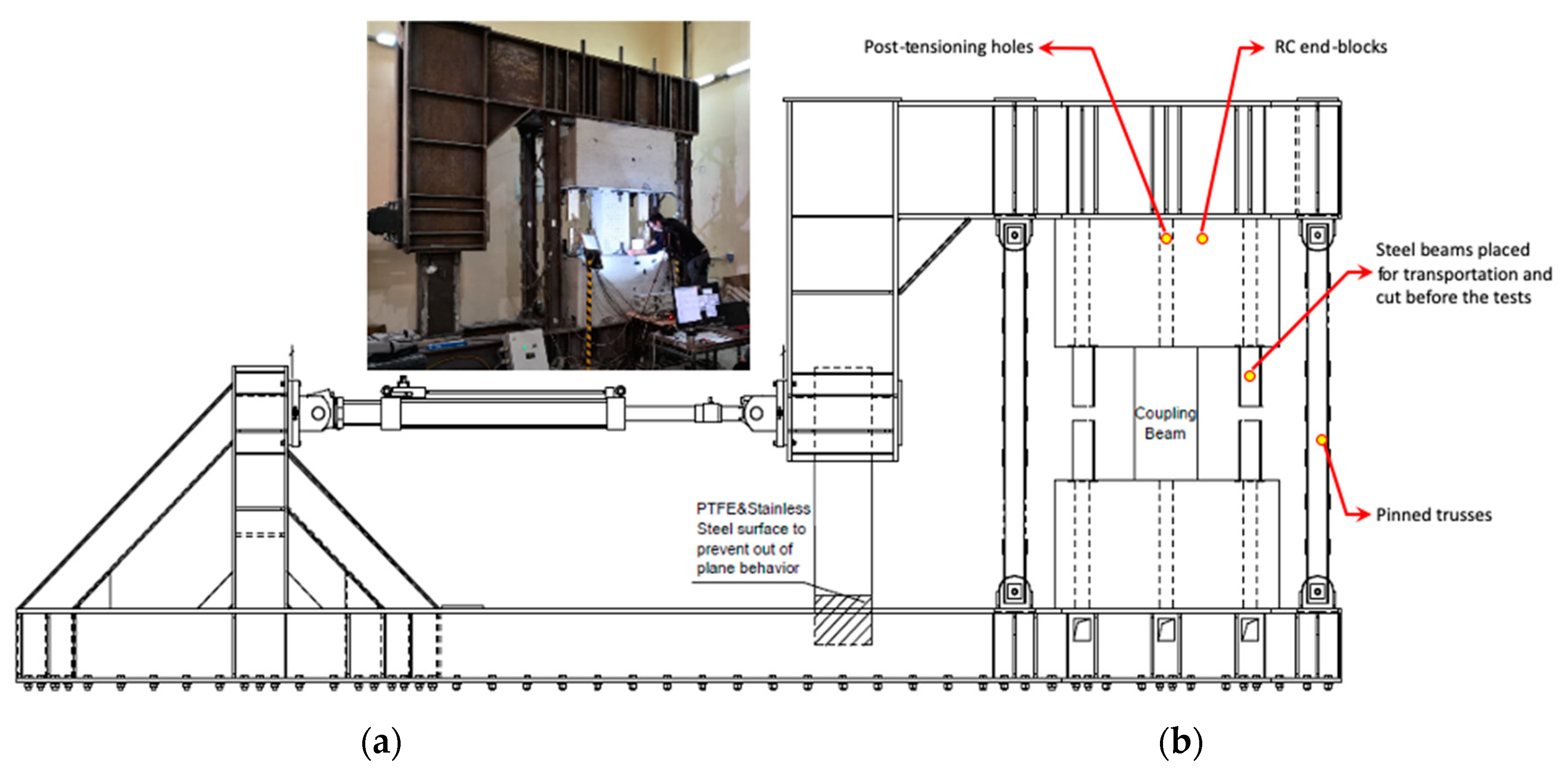
All samples were tested by the experimental tester. The image of the test device was shared in
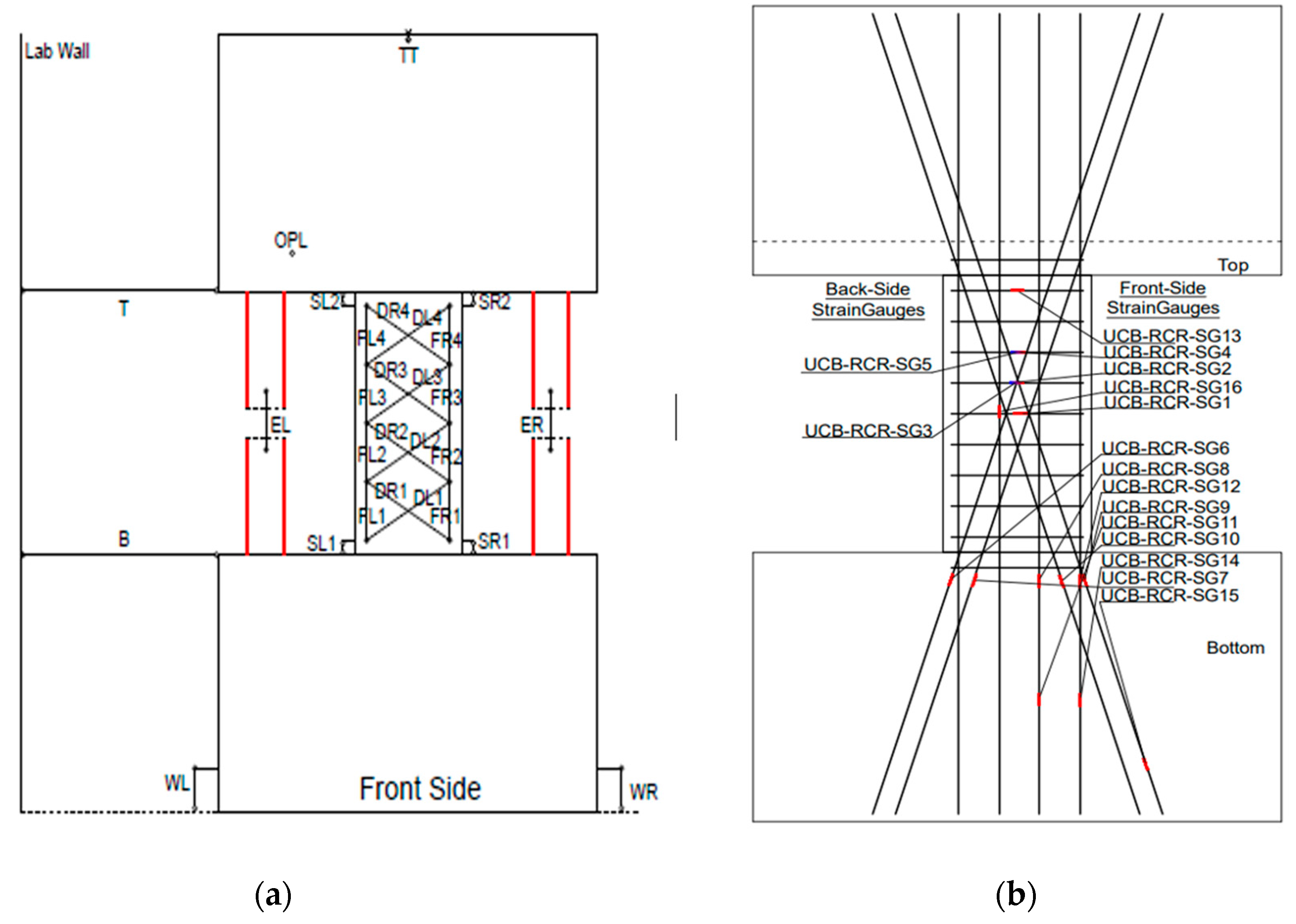
Figure 4. As the tester is a self-contained closed system, it does not need a rigid reaction wall. Samples were placed perpendicular to the instrument. Post-tension is applied so that the upper and lower blocks have a rigid connection. In this way, it is guaranteed that the tester has built-in node grades. Differential displacements between the steel frame and blocks were monitored throughout the test. 4 vertical pin-connected steel columns are attached to both sides of the coupling beam. This is because the coupling beam prevents any rotation at the top block joint during testing. A rigid box fitted under the L-shaped loading frame is designed to prevent out-of-plane rotation and torsion behavior of the frame and to slide between the lower H profiles. Used polytetrafluoroethylene (PTFE), stainless steel surface, and grease lubricated to minimize friction and provide adequate pressure resistance. The lateral load was applied via three horizontal actuators. The lateral load passing through the mid-span (mid-height) of the test specimen provided zero moments at the mid-span of the beam.
2.4. Loading Protocol
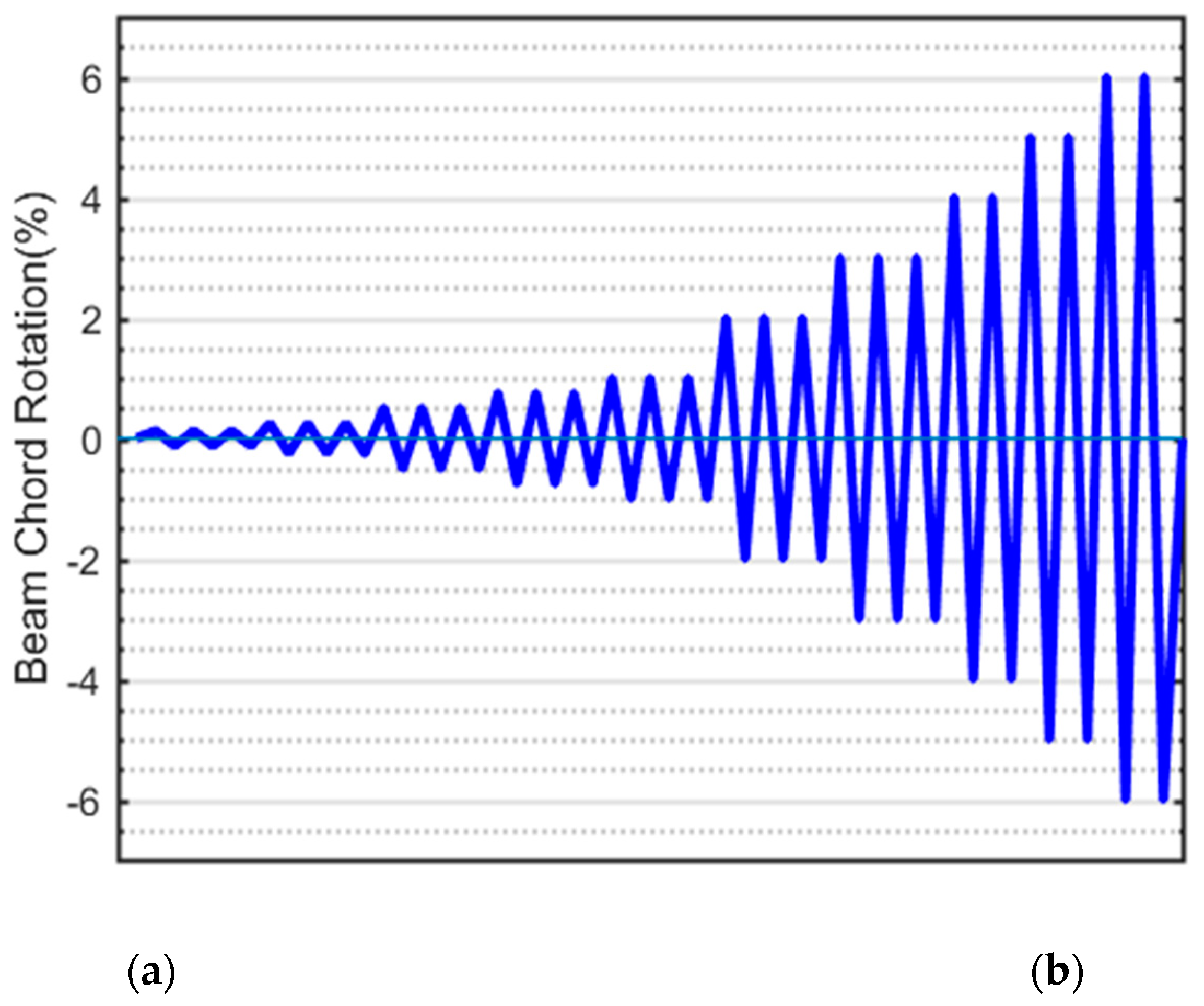
The testing procedure for all samples followed a displacement-controlled reversal test method. The displacement control was achieved by steadily increasing the beam chord rotation. The beam chord rotations were calculated as the ratio of the relative displacement perpendicular to the beam axis at the ends to the clear beam span.
For each increment of 3% beam rotation, three cycles were applied to the samples. However, beyond 3% beam rotation, two cycles were conducted for each subsequent increment (as illustrated in
Figure 5).
This displacement-controlled reversal test approach allowed for a thorough assessment of the coupling beams’ performance under cyclic loading conditions, capturing valuable data on their behavior and response to seismic forces.
2.5. Instrumentation
Strain gauges played a crucial role in our experimental setup, providing valuable data on the behavior of the coupling beams during testing. We strategically placed strain gauges on longitudinal, diagonal, and transverse reinforcements to monitor their respective stress and deformation responses. Additionally, some strain gauges were affixed to the stirrups of the diagonal bundles and the section stirrups in the middle position.
To gain insights into the stress penetration within the wall, we carefully positioned strain gauges along the development length of the diagonal and longitudinal bars. TML – YFLA-5-3L type strain gauges were utilized in our study due to their reliability and precision.
Moreover, we placed sixteen strain gauges at the midpoints of the pin-tipped columns to observe the deformation and resulting stresses arising from the elongation of the connecting beam. These measurements were crucial in understanding the interaction between the coupling beam and the surrounding test setup.
In addition to the strain gauges, we employed potentiometers to measure bending, shear, shear-elongation, shear, and axial deformations along the beam (as depicted in
Figure 6). However, it should be noted that data could not be obtained from the specimens after the strengthening process for 16 strain gauges placed following damage, which rendered them unusable for further testing. Nevertheless, potentiometers positioned on pendulums and on the sample were successfully employed to capture important data during the experiments.
3. Strengthening
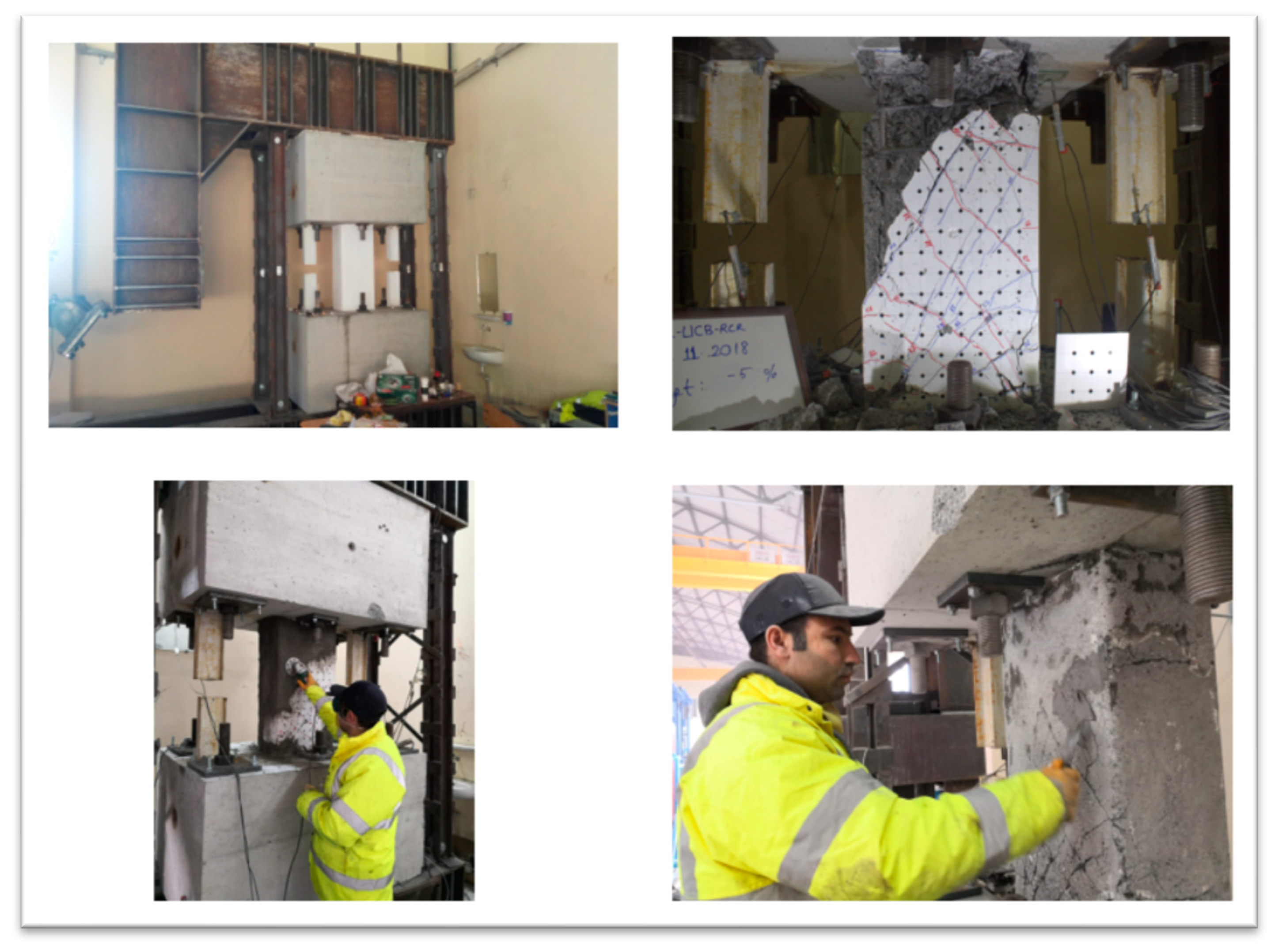
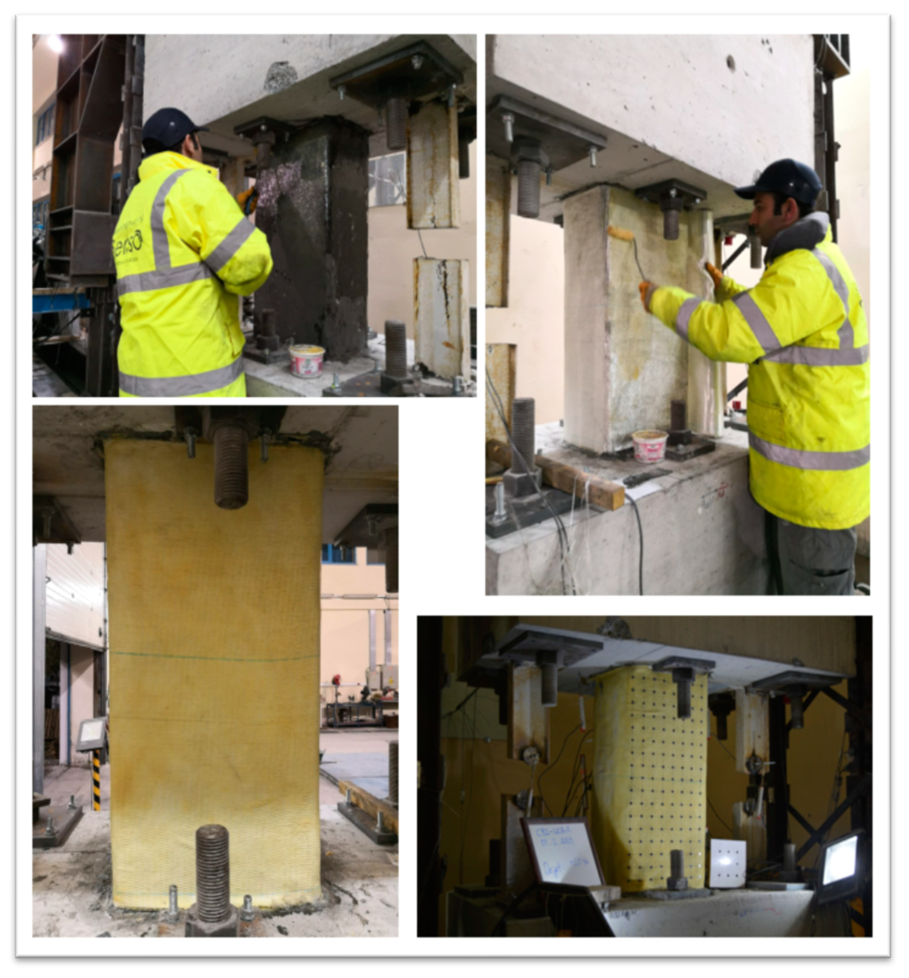
The damaged specimens resulting from the experiments were initially repaired using Teknorep 300-ex repair mortar. Once the rough surface of the mortar dried, it was cleaned by using sandpaper. Subsequently, the sample edges were rounded to a diameter of 3 cm in preparation for wrapping. Any bird’s eye gaps and capillary cracks that formed in other damaged areas of the samples were closed using Mapei Adesilex metered mixture (an epoxy repair solution). The surfaces where Mapewrap 31 T/A epoxy was applied were then wrapped with 2 layers of Tyfo SEH-25A FRP, completing the retrofitting process. The preparation stages are illustrated with images in
Figure 7 and
Figure 8 below.
4. Experimental Results and Discussion
In this section, the test results will be presented and discussed. The variations in shear vs. chord rotation, axial elongation, and effective stiffness will be discussed to gain insights into the findings. Although a substantial amount of data was collected, only the most significant results will be highlighted here, as previously mentioned in the preceding section. All experimental studies have been uploaded to an online platform and will be made freely available upon request [
16].
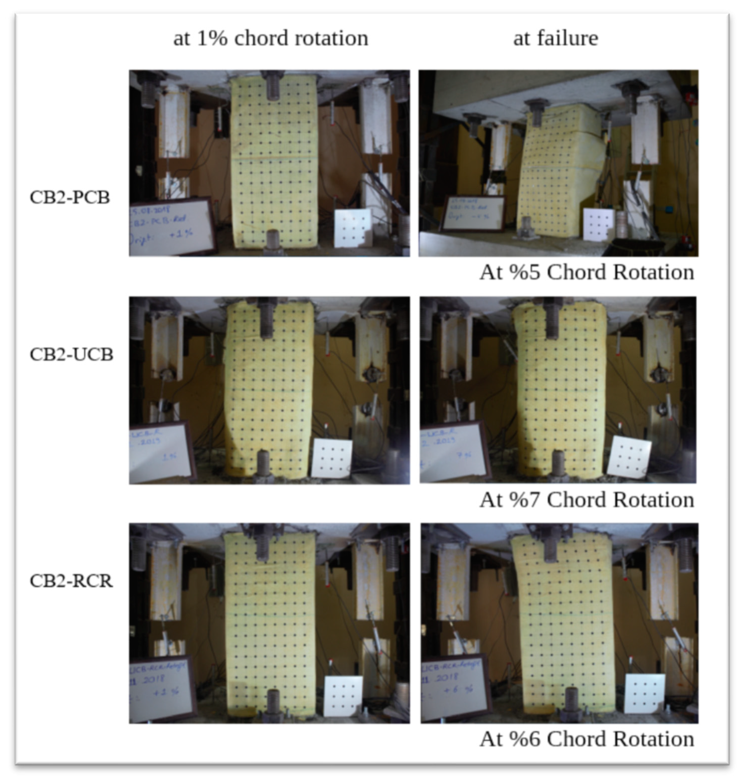
It is important to note that chord rotation was utilized for the deformation measurements in the samples examined in this study. Chord rotation is a widely accepted method for assessing deformations in coupling beams. Additionally, a decrease in strength of approximately 25% from the maximum attainable strength is considered to define the failure mechanism of the coupling beam.
Figure 9 displays the 1% chord rotation and collapse mechanism of the tested samples.
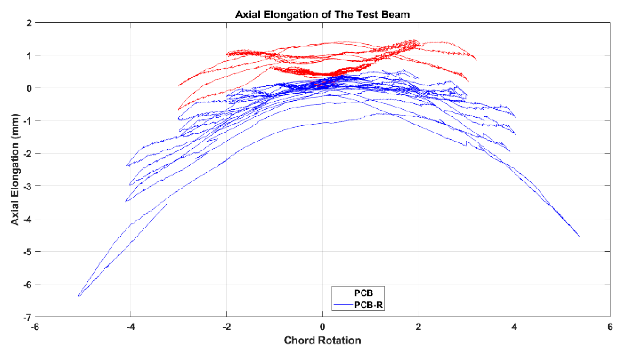
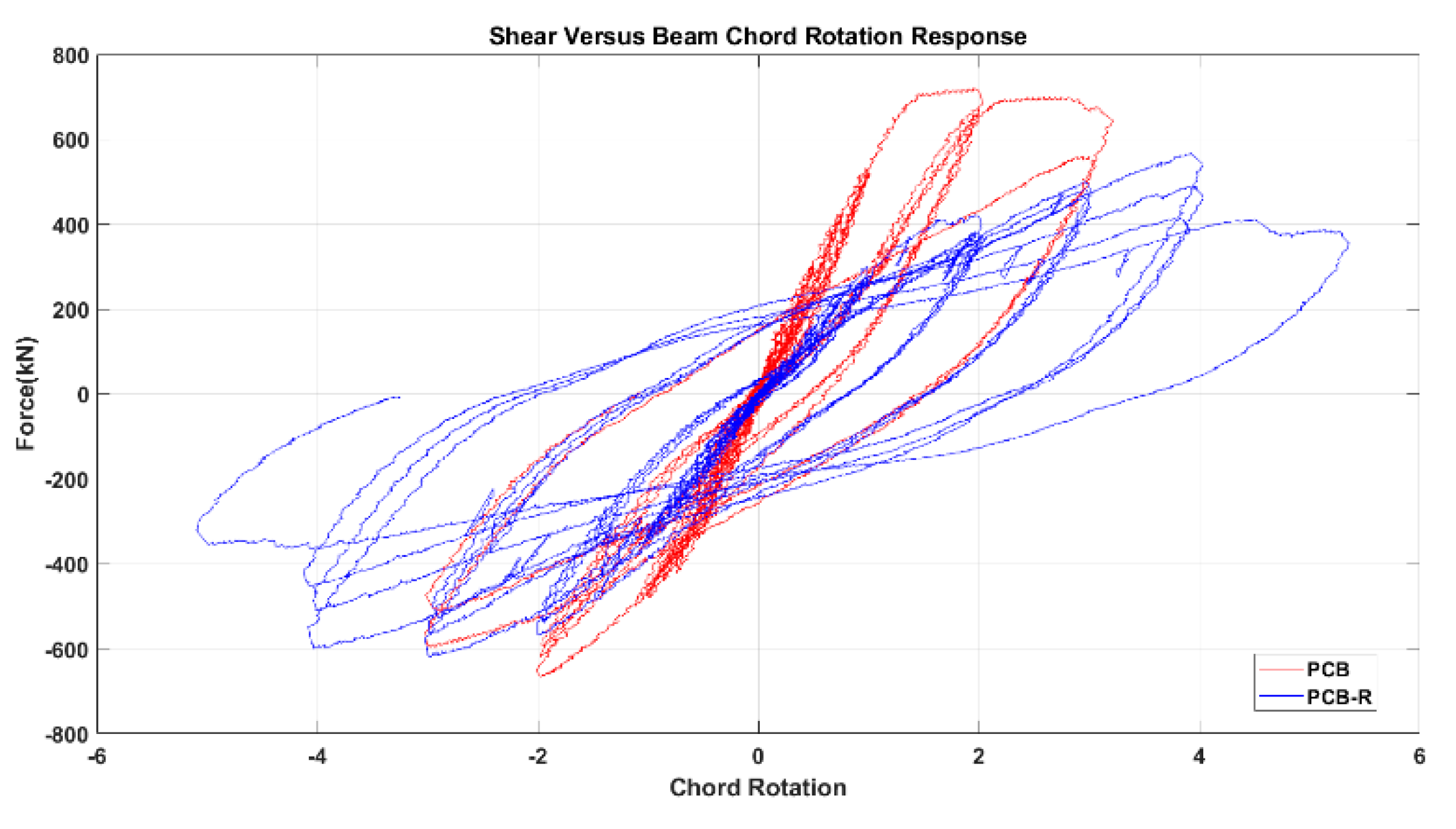
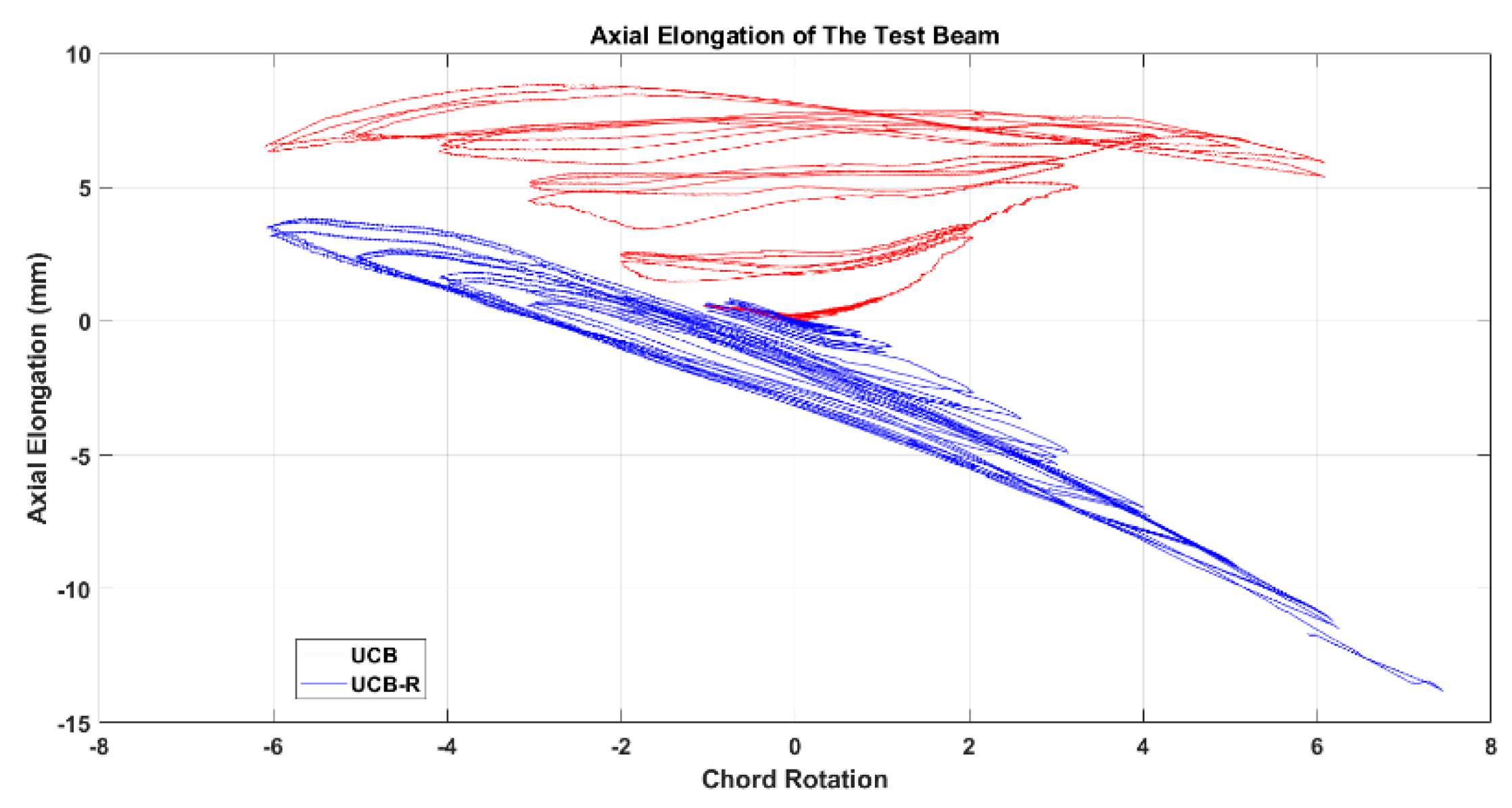
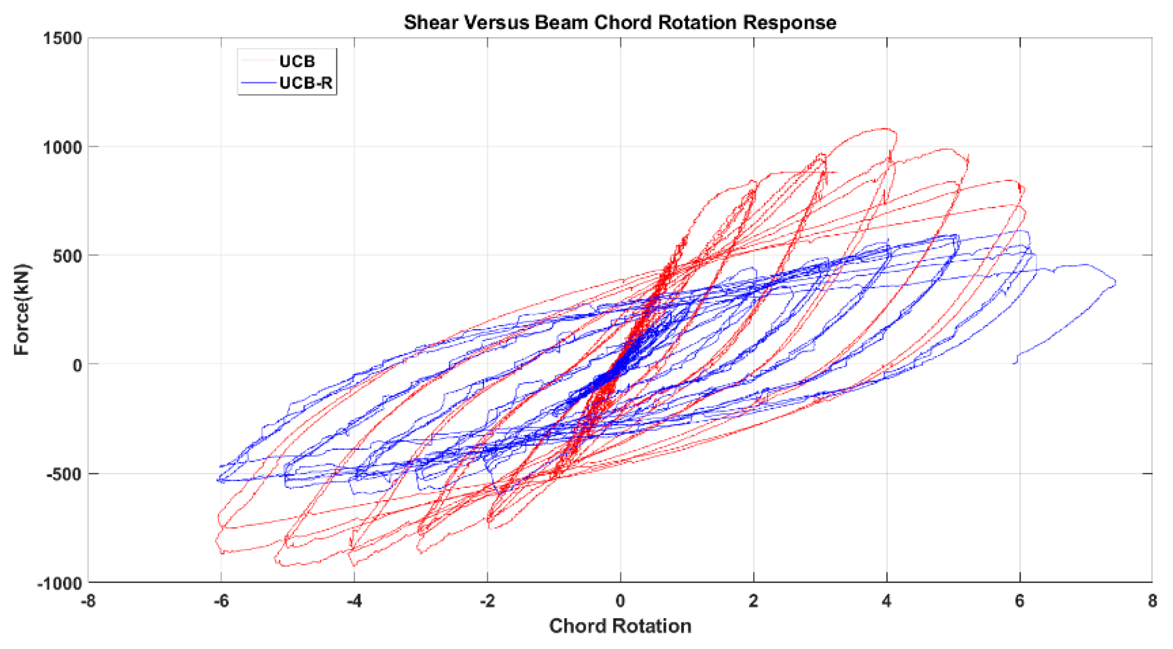
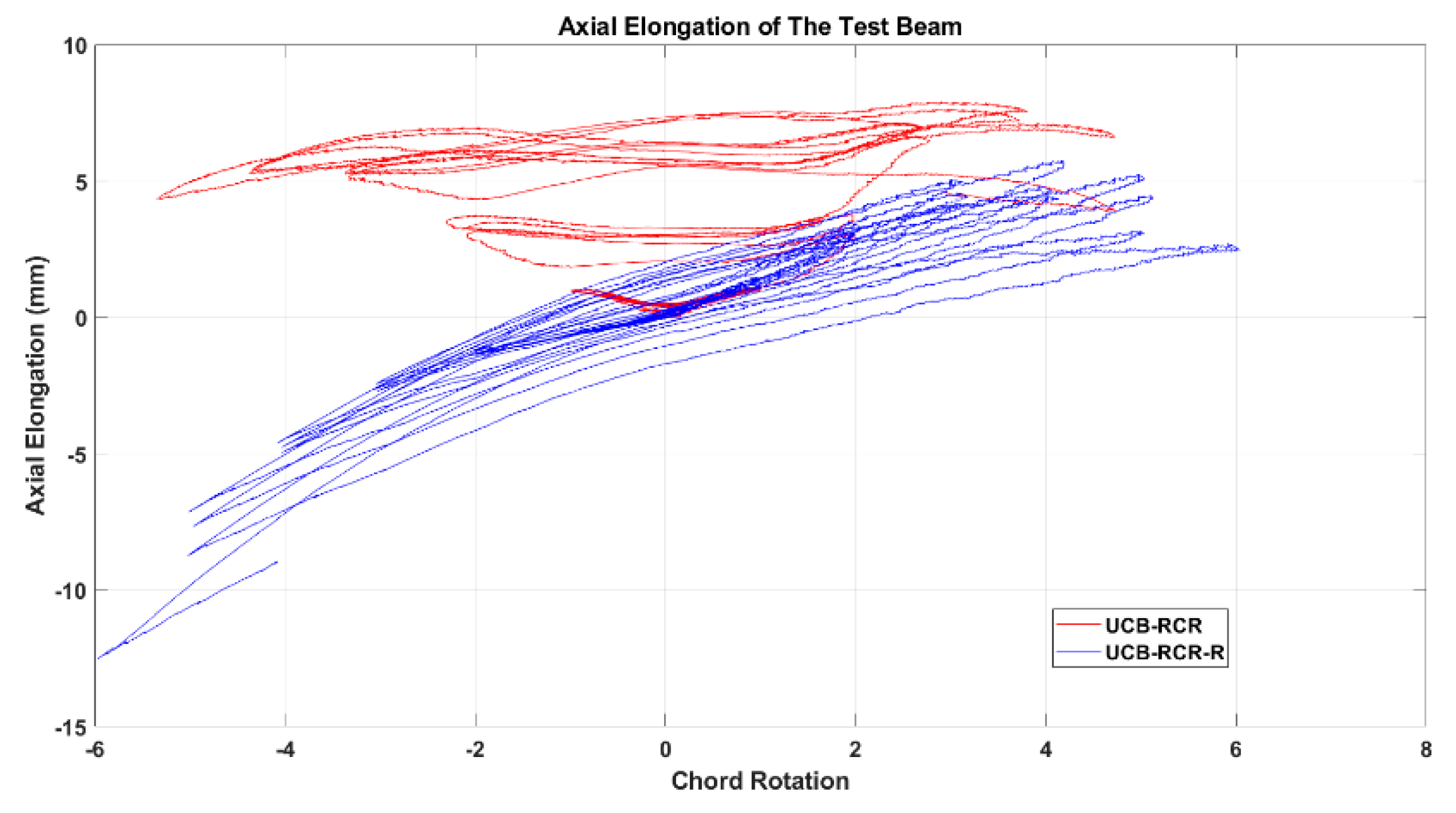
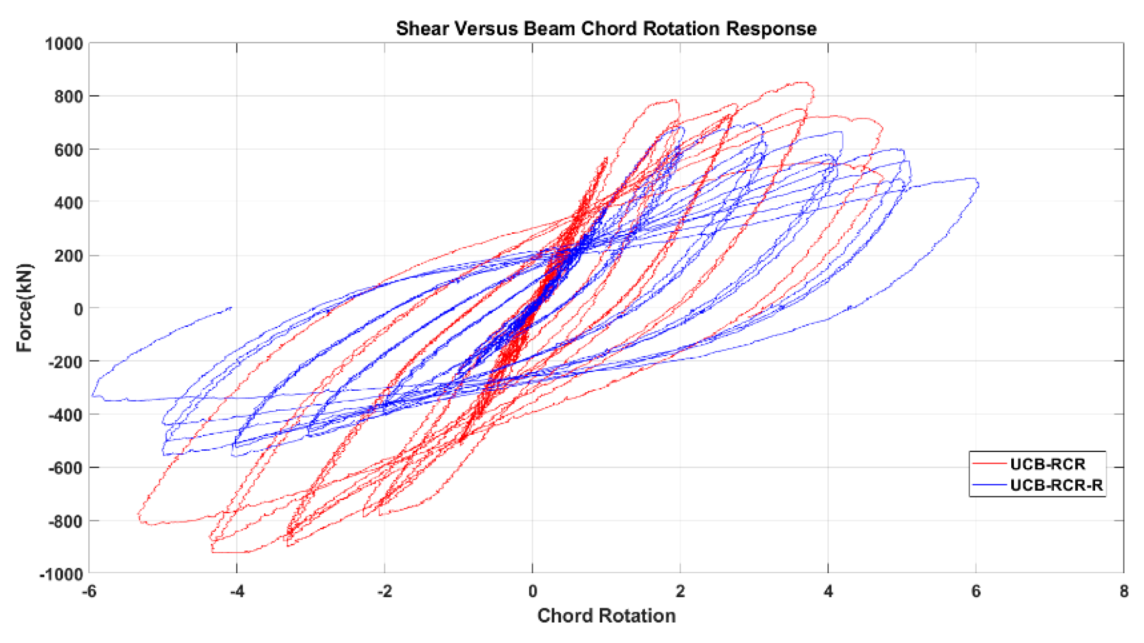
The test results, depicted in
Figure 10,
Figure 11,
Figure 12,
Figure 13,
Figure 14 and
Figure 15, include the axial elongation and shear force distribution via chord rotation. Notably, the axial elongation values predominantly exhibited negative behavior. This can be attributed to several factors associated with the repair and retrofitting process of the damaged beam:
Closure of Cracks: The use of repair mortar without epoxy injection has not resulted in the closure of cracks in the beam, which had previously experienced high drifts and wide crack formation. During cyclic loading, the main surfaces of the beam had come into contact with each other, leading to the closure of the cracks.
Plastic Elongation and Buckling: The observed plastic elongation in the reinforcement and the presence of buckling could have been influenced by the advanced level of buckling experienced in the previous experiment. The buckling phenomenon might have reached an advanced stage during the subsequent tests.
Damage Patterns: Further examination of the damages from the previous test revealed distinctive behaviors in different beam types. For instance, in the case of the Primary Coupling Beam (PCB), negative elongation was observed throughout the entire cycle. This behavior can be primarily attributed to the PCB’s loss of capacity due to concrete and stirrup rupture in the middle region. Similar damage patterns of negative elongation were observed in Reduced Section Confinement Ratio (RCR) and Unconfined Bundle (UCB) beams, where reinforcement buckling and concrete rupture occurred in the end regions. Negative elongation occurred when the concrete ruptured and reinforcement buckling took place, while limited positive elongation was observed in the other direction. These damage patterns observed in the experiments align with those typically observed in the failure stage.
In conclusion, the negative axial elongation values observed in the tests can be attributed to the closure of cracks, plastic elongation, and buckling effects in the beams under cyclic loading. These findings provide valuable insights into the behavior of the repaired and retrofitted coupling beams, shedding light on their structural response and potential failure mechanisms. Understanding these factors is crucial for developing effective retrofitting strategies to enhance the seismic resilience of reinforced concrete structures.
When examining the three fundamental properties of hysteresis response, ultimate strength, initial stiffness, and degradation, the following observations were made for each sample:
Partial Confined Bundle (PCB) Sample:
The strength of the PCB sample before strengthening was higher than after strengthening, but the rate of strength reduction decreased after damage.
The initial stiffness decreased by approximately 50% after damage, considering 1% chord rotation.
The degradation increased rapidly after reaching the displacement corresponding to ultimate strength as the confinement effect disappeared in the first test state. However, the strengthened state still showed desired performances by exceeding the targeted displacements.
Unconfined Bundle (UCB) Sample:
The ultimate strength amounts of the UCB sample were still higher before strengthening at ongoing chord rotations. However, in the strengthening state also ultimate strength reaches the half time of ultimate strength with the same chord rotation level.
The initial stiffness again decreased by roughly 50% compared to the 1% chord rotation value after damage.
The degradation types were similar to the initial state in the retrofitted sample but increased further with the disappearance of the wrapping effect at the end of the test.
UCB-Reduced Confinement Ratio (RCR) Sample:
The strength amounts were close in the first cycles, but as the number of cycles increased, the strength of the strengthening specimen decreased further due to inner damage.
There was roughly a 40% difference between the initial stiffness value and the 1% chord rotation value.
The degradation levels were higher in the initial test sample with the ongoing chord rotations and the strengthening sample went on a higher chord rotation level due to the higher confinement ratio.
In general, the strengthened samples performed with lower strength and initial stiffness, along with similar degradation levels, until the confinement effect was lost due to damage. However, it is worth noting that the strength observed was still around the ultimate design strength value (VUCBultimate:506.6kN, VPCBultimate:514.7kN, VUCB-RCRultimate:526.2kN) and the chord rotation value reached and even passed a minimum of 3% drift in all samples. Therefore, it is believed that this urgent strengthening technique holds the potential to effectively enhance the seismic resilience of coupling beams subjected to forces up to the collapse drift, significantly increasing the safety of the overall structure.
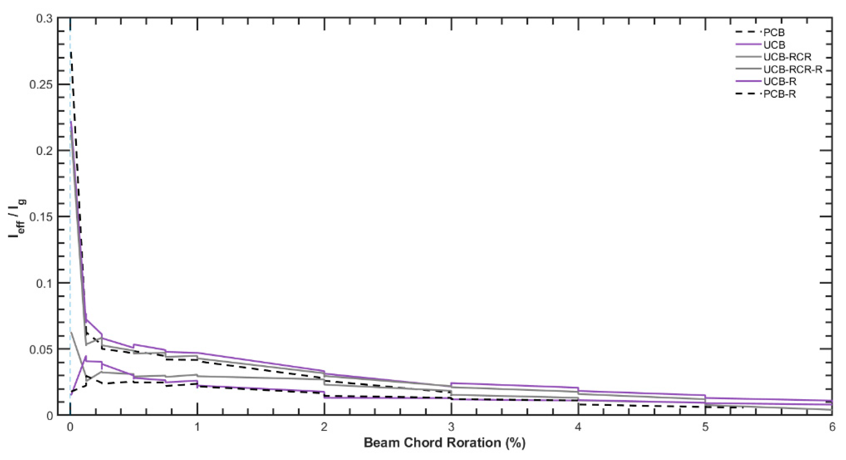
When analyzing the effective stiffness values,
Figure 16 indicates that the values at the end of the tests before strengthening are predominantly maintained during the tests conducted after the strengthening process. This observation suggests that the strengthening measures applied to the samples have effectively preserved their overall stiffness characteristics, especially after 2% chord rotation. This finding suggests that the retrofitting measures, such as GFRP wrapping and repair mortar application, effectively maintain the overall stiffness of the coupling beams even after undergoing cyclic loading and experiencing damage. The strengthening technique has successfully enhanced the structural stiffness, contributing to the improved performance and seismic resistance of the coupling beams throughout the test cycles. This finding further supports the feasibility and efficacy of the proposed strengthening approach in maintaining the structural integrity and enhancing the safety of the coupled wall systems..
The ability to retain effective stiffness is crucial for the structural performance of coupling beams, as it ensures that the beams can continue to provide the necessary lateral stiffness and ductility during seismic events. By demonstrating the capability to preserve effective stiffness through strengthening, this study further supports the feasibility and reliability of the proposed method in enhancing the seismic resilience of reinforced concrete structures.
5. Conclusions
This study investigated the seismic behaviors of post-earthquake damaged reinforced concrete coupling beams strengthened with Glass Fiber Reinforced Polymer (GFRP), aiming to present a rapid and effective post-earthquake strengthening solution. Through experimental tests on half-scale diagonally reinforced concrete coupling beams with various detailing options, including reduced confinement ratio, and partially confined, and unconfined bundles, the performance of the rapid GFRP wrapping method was thoroughly evaluated under cyclic loading protocols.
The experimental results unequivocally demonstrate that GFRP wrapping significantly improves the seismic performance of post-earthquake damaged coupling beams, even in the presence of more than 25% strength loss which means failed specimens. The strengthened beams exhibit commendable ductility, maintaining high levels of deformation capacity after strengthening, although there is a notable reduction in overall stiffness. Moreover, the chord rotation level of the strengthened beams complies with the stringent requirements of ACI 318, Eurocode 8, and the Turkish Earthquake Code.
This study underscores the effectiveness of GFRP as an efficient solution for enhancing the post-earthquake performance of damaged coupling beams. The strengthened beams exhibit commendable ductility and high-level deformation capacity. By demonstrating the capability to preserve effective stiffness through strengthening, this study further supports the feasibility and reliability of the proposed method in enhancing the seismic resilience of RC structures.
After conducting the tests on the samples, their failure mechanisms were carefully examined. Upon evaluating the GFRP-strengthened specimens by opening the concrete cover at the end of the test, researchers observed rupture in the longitudinal and transverse reinforcements in regions experiencing high stress or deformation demands. This observation provided valuable insights into the behavior of the strengthened specimens under load and offered a clearer understanding of the performance of GFRP materials in enhancing the structural integrity of coupling beams. The influence of section confinement level on the performance of the coupling beams has been established as key factors that dictate the success of the strengthening strategy. Therefore, careful consideration and meticulous implementation of these aspects during the design phase are of utmost significance.
Moreover, this study highlights the urgent need for post-earthquake strengthening measures in high-rise buildings with structural walls. Swift and proactive implementation of strengthening procedures is vital, given the potential damage and collapse mechanisms that earthquakes and other extreme conditions may trigger. By addressing practical structural scenarios encountered in real-life situations, the research contributes to the development of effective strengthening strategies and the adoption of timely emergency measures.
In conclusion, this study represents a significant advancement in understanding the post-earthquake behaviors of reinforced concrete coupling beams and assessing the efficacy of GFRP strengthening techniques. Its findings offer valuable guidance for structural engineers, architects, and policymakers in making informed decisions regarding post-earthquake strengthening projects. Ultimately, the research contributes to enhancing the seismic resilience of buildings and promoting overall safety in earthquake-prone regions..
Author Contributions
Conceptualization, N.E. and İ.E.B.; methodology, A.İ.; software, E.T.; validation, A.İ., K.O. and İ.E.B.; formal analysis, N.E and E.T.; investigation, N.E.; resources, A.İ. and İ.E.B.; data curation, N.E.; writing—original draft preparation, N.E, E.T., İ.E.B, A.İ, K.O; writing—review and editing, K.O. A.İ, İ.E.B; visualization, N.E. and E.T.; supervision, İ.E.B.; project administration, İ.E.B.; funding acquisition, N.E., E.T, A.İ, İ.E.B. All authors have read and agreed to the published version of the manuscript.
Funding
This research was funded by Yapı Merkezi Prefabrikasyon Inc.
Institutional Review Board Statement
Not applicable.
Data Availability Statement
The data used to support the findings of this study are included within the article.
Acknowledgments
The authors express their gratitude to Mr. Orhan Manzak. Support by Yusuf Gürel, as well as the by Prof. Güray Arslan and Prof. Yusuf Ayvaz from Yıldız Technical University for providing access to the laboratory for the experiments, are gratefully acknowledged.
Conflicts of Interest
The authors declare no conflict of interest.
References
- Paulay, T.; Binney, J.R. Diagonally Reinforced Coupling Beams of Shear Walls. Shear in Reinforced Concrete, SP-42, American Concrete Institute, Farmington Hills, MI, 1974, 579-598. [CrossRef]
- Galano, L.; Vignoli, A. Seismic Behavior of Short Coupling Beams with Different Reinforcement Layouts. ACI Structural Journal 2000, 97, 876–885. [Google Scholar] [CrossRef]
- Gonzalez, E. Seismic Response of Diagonally Reinforced Slender Coupling Beams. Master Thesis, Department of Civil Engineering, The University of British Columbia, Vancouver, BC, Canada, 2001. [Google Scholar]
- Wallace, J.W. Behavior, design, and modeling of structural walls and coupling beams - Lessons from recent laboratory tests and earthquakes. International Journal of Concrete Structures and Materials 2012, 6, 3–18. [Google Scholar] [CrossRef]
- Han, S.W.; Lee, C.S.; Shin, M.; Lee, K. Cyclic performance of precast coupling beams with bundled diagonal reinforcement. Engineering Structures 2015, 93, 142–151. [Google Scholar] [CrossRef]
- Eser, N.; Tore, E.; Orakçal, K.; Ilki, A.; Bal, I.E. Diagonally Reinforced Coupling Beams with Varying Reinforcement Details. Elsevier Structure Journal (Submitted). 2023.
- Riyazi, M.; Esfahani, M.R.; Mohammadi, H. Behavior of coupling beams strengthened with carbon fiber reinforced polymer sheets. International Journal of Engineering 2007, 20, 49–58. [Google Scholar]
- Honarparast, S.; El-Saikaly, G.; Chaallal, O. Externally bonded carbon fiber–reinforced polymer composites for seismic retrofit of reinforced concrete coupling beams designed according to old codes. Advances in Structural Engineering. 2019, 22, 1412–1425. [Google Scholar] [CrossRef]
- Xian, Li; Lu, Liu; Heng-Lin, Lv; Shi-Yu, Sha. Seismic retrofit of short RC coupling beams using CFRP composites. Magazine of Concrete Research. 2016, 68, 260–270. [CrossRef]
- Turkish Seismic Design Code. Republic of Türkiye Prime Ministry Disaster & Emergency Management Authority – AFAD. 2018.
- ACI Committee 318. Building Code Requirements for Structural Concrete (ACI 318M-19) and Commentary (ACI 318RM-19). American Concrete Institute. 2019.
- Eurocode 8. Design provisions for earthquake resistance of structures. Brussel. 1998.
- Tyfo SEH-25A Composite Technical Sheet. Available online: https://www.power-mesh.com/pdf/tyfoseh25A.pdf (accessed on 20 July 2023).
- Teknorep 300 Ex Technical Sheet. Available online: https://teknoyapi.com.tr/documents/TDS-EN-teknorep-300-ex.pdf (accessed on 20 July 2023).
- Mapewrap-31-t Technical Sheet. Available online: https://www.mapei.com/it/en/products-and-solutions/products/detail/mapewrap-31-t (accessed on 20 July 2023).
- Online Test Data Repository for this study. Available online: https://data.4tu.nl/datasets/4c0c2b23-97e9-4b2f-8e0f-00f32068411a (accessed on 20 July 2023).
|
Disclaimer/Publisher’s Note: The statements, opinions and data contained in all publications are solely those of the individual author(s) and contributor(s) and not of MDPI and/or the editor(s). MDPI and/or the editor(s) disclaim responsibility for any injury to people or property resulting from any ideas, methods, instructions or products referred to in the content. |
© 2023 by the authors. Licensee MDPI, Basel, Switzerland. This article is an open access article distributed under the terms and conditions of the Creative Commons Attribution (CC BY) license (http://creativecommons.org/licenses/by/4.0/).
