1. Introduction
One of the most common types of coating failure is the violation of solidity due to cracking, as well as peeling of coatings [
1,
2]. Currently, to assess cracking, non-destructive testing methods are used, for example, eddy current, magnetic and ultrasonic. They allow you to identify surface and subsurface defects in materials.
The Finite Element Model (FEM) is often used to simulate crack formation [
3].
V.V. Shneiderova [
4] proposed a method for assessing the crack resistance of protective and decorative coatings. The technique consists in modeling the process of crack formation in a reinforced concrete element, during which cracks are created in the concrete under the coating. The state of the coating above the crack of the measured width is assessed by its continuity at a 20-30-fold increase through an optical device. The crack resistance index is taken as the width of the crack opening preceding the one when the formation of the first defect in the coating above the crack was noticed.
Recently, a new scientific direction has been widely developed - fracture mechanics. The application of the concepts of fracture mechanics makes it possible to obtain qualitative and quantitative characteristics of crack resistance. The English scientist Griffiths formulated an energy approach to the quantitative assessment of crack resistance precisely from the standpoint of modern fracture mechanics. The main idea was that the potential energy of the body, accumulated by it in the process of elastic deformation, at the beginning of destruction is completely spent on the formation of new surfaces [
5].
In [
6,
7], the digital image processing (PIV) method is used to determine the displacements and the presence of cracks in the sample. PIV is the international name for the digital tracer imaging method. Particle Image Velocimetry (PIV) belongs to the class of non-contact measurement methods. By processing digital images, the fields of particle displacements, shear and volume deformations, etc. can be obtained
The acoustic emission method is also used to assess crack resistance [
8,
9,
10,
11]. With its help, it is possible to identify actively developing defects. The samples were tested on a tensile testing machine of the FM-1000 type using an acoustic emission device (AED). The development of an acoustic device for measuring the increase in the surface of a crack in the process of its abrupt development is based on an empirical dependence [
12,
13,
14].
where
ΔS is the increase in the surface of the crack in the process of its abrupt development;
E is the modulus of elasticity of the material;
K1 - stress intensity factor;
A is the amplitude of the acoustic emission signal during a crack jump;
с - coefficient of proportionality.
When K
1 reaches the value of K
c*, expressing K
c* in terms of the crack length and the effective voltage, we get:
where
σ is the average voltage;
l is the reduced length of the defect.
The right-hand side of equation (2) is the total work of fracture due to crack growth. This makes it possible to determine the destruction energy of the material from the sum of the squares of the amplitudes of the acoustic emission signals [
15,
16,
17].
Of interest is the use of the AE method for assessing the resistance of coatings to cracking and flaking. When using the AE method, it is possible to observe the degradation of materials, the formation and increase in the size of defects. During loading, acoustic emission (AE) is recorded only with the onset of microplastic deformation, that is, it is directly related to the motion of defects.
In 2019, the International Organization for Standardization (ISO) developed three new standards:
Standard ISO 16836 Non-destructive testing. Acoustic emission control of technical condition. Method for measuring AE signals in concrete [
18];
Standard ISO 16837 Non-destructive testing. Acoustic emission control of technical condition. Method of qualification assessment of damage in reinforced concrete beams [
19];
ISO 16838 Standard Non-Destructive Testing. Acoustic emission control of technical condition. Method for the classification of active cracks in concrete structures. [
20].
The area of application of these standards is the method for measuring signals in concrete and practical methods for monitoring the technical condition of a structure made of concrete and reinforced concrete by the AE method.
Application of the method of acoustic emission in assessing the durability of protective and decorative coatings will optimize the composition of paints, predict their durability in order to obtain coatings with a set of specified properties
2. Materials and Methods
To assess the regularities of changes in the properties of coatings during aging, we used polyvinyl acetate PVAC, polymerized lime, acrylate, alkyd PF-115 and oil paints. Paints were applied to solution substrates in two layers with intermediate drying for 20 min. In this case, the porosity of the substrate was varied from 20% to 28%. After curing the coatings for 28 days, the colored solution samples were subjected to thermal aging at a temperature of 60°C, freeze-thaw. The adhesion of the coatings was determined by the normal peel method. When the washer was torn off, the nature of the destruction of the coatings was recorded. To assess the crack resistance of the coatings, the method of acoustic emission was used.
The samples were tested on a tensile testing machine of the FM-1000 type using an acoustic emission device (AED). In our studies, acoustic emission of samples was studied using an acoustic emission device (AED) based on a standard AF-15 device. AED made it possible to record all the most important parameters of AE signals: amplitude, duration of the acoustic emission signal, intensity, total number of individual AE events, total AE energy in accordance with GOST 25.002-80 "Calculations and strength tests in mechanical engineering. Acoustic emission. Terms, definitions and designations". The acoustic emission device (AED) includes a recorder of the type Н-338 and dual-beam universal oscilloscope С1-74.
The acoustic emission device, which was used to receive and record AE signals, is characterized by a preamplifier input sensitivity of less than 2 mV in the frequency range of 50–150 kHz. The informative parameters of the AE were the total number of AE signals at two discrimination levels and the signal energy. The loading was carried out in steps of 0.1 of the expected strength. At each stage of loading, the samples were kept until the termination of the AE. The speed of movement of the gripper in all experiments was the same and amounted to 100 · 10-10 m / s. Analysis of the numerical values of the energy of the AE signals on the loading curve of the prototypes makes it possible to judge the nature of destruction and the degree of brittleness of the coatings. As a sensitive element of the AE signal converter, piezoceramics of the lead zirconate titonate type TsTS-19 is used. In order to obtain a good acoustic contact, the AE transducer was pressed with a constant force to the end surface of the prism sample through a thin layer of petrolatum grease using a special rubber band or attached to this surface using a fast-drying glue, for example, cyocrine.
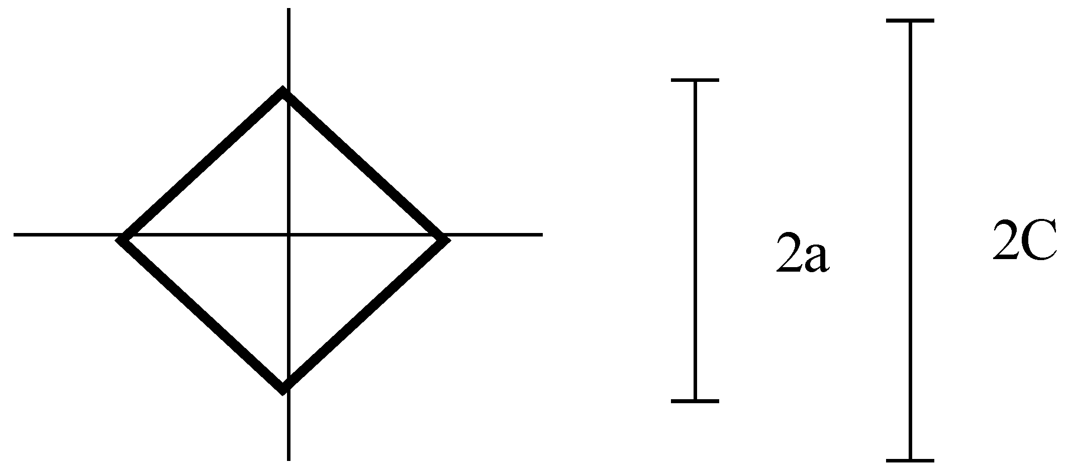
To assess the crack resistance of the coatings, the stress intensity factor K
1c was determined using a Vickers indenter (
Figure 1).
To do this, we determined the length of radial cracks formed from the corners of the Vickers indenter indentation and the indentation diameter [
21]. The critical coefficient of intensity of tension was determined by a formula
where H –Vikkers’s hardness;
C – semi-length of radial cracks;
а –semi-length of diagonal print
3. Results
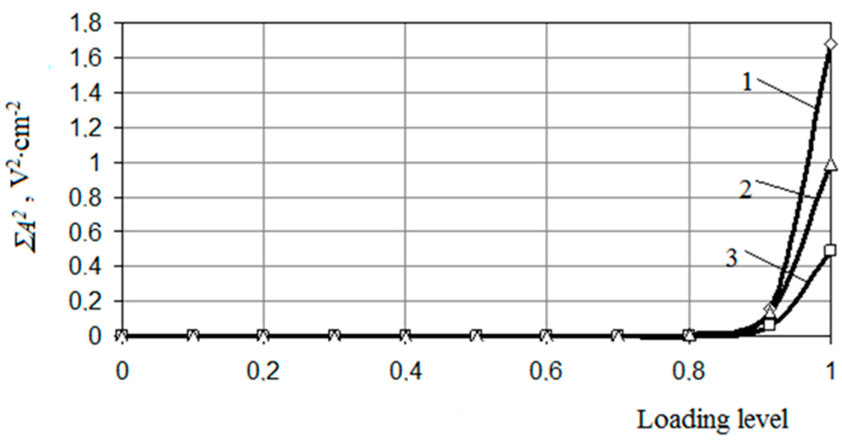
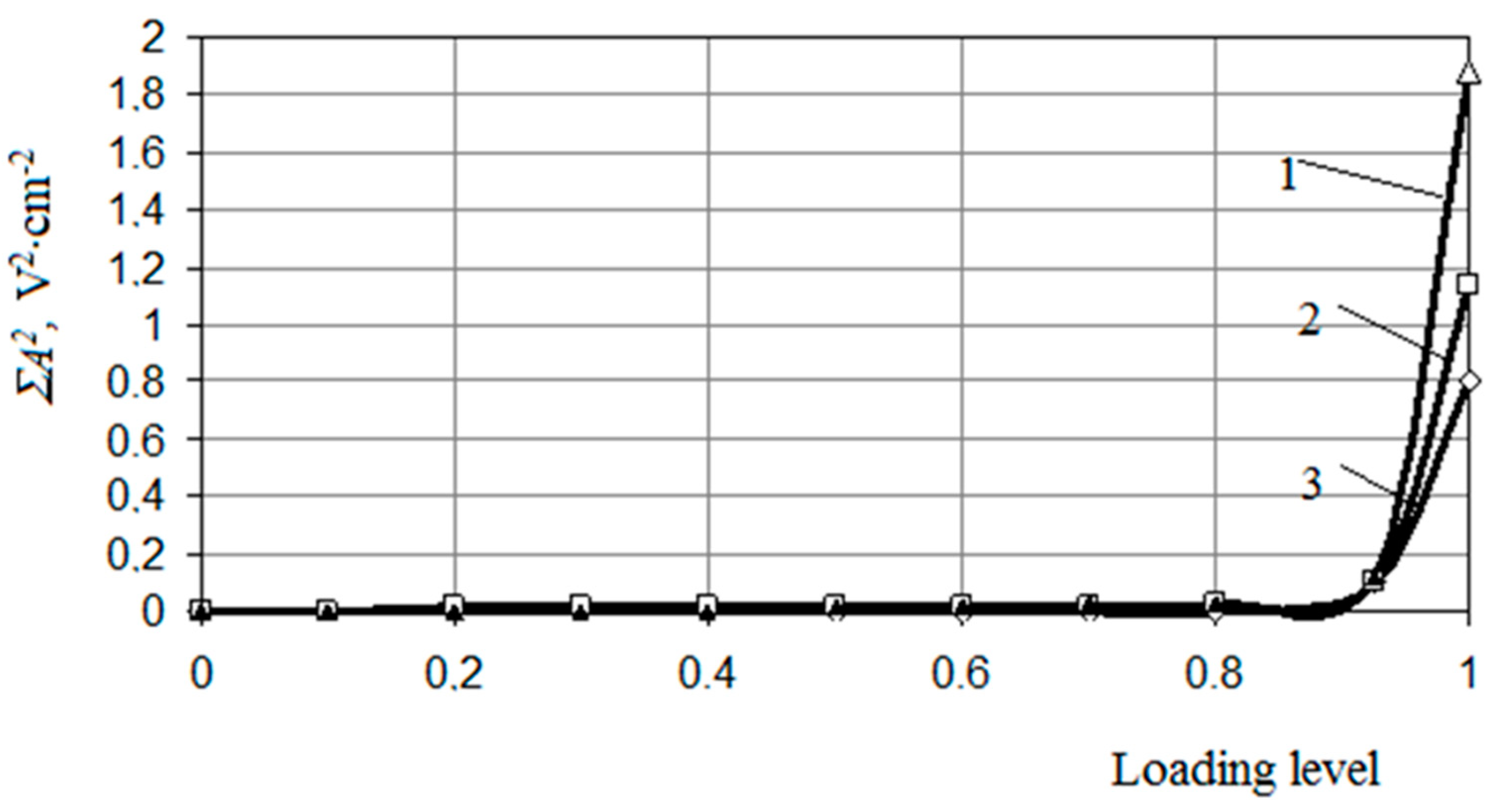
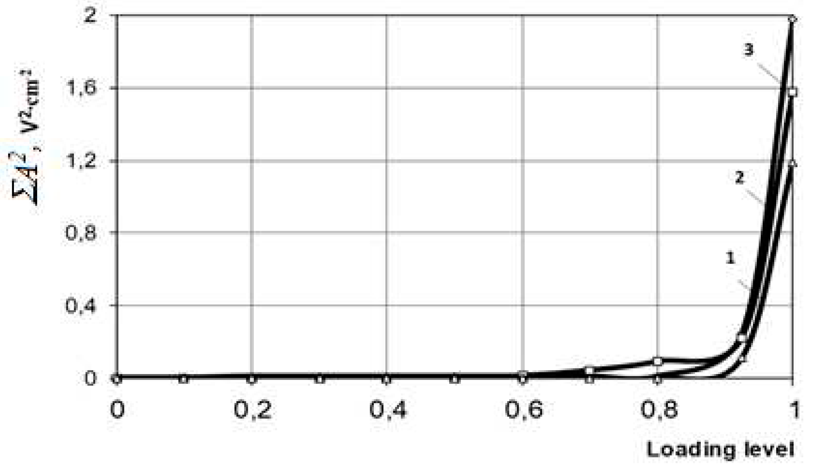
According to the data shown in
Figure 2,
Figure 3 and
Figure 4, one can judge the processes occurring in the coatings after curing and heat-treatment. At the same time, we can talk about a significant effect of aging factors on the nature of destruction of protective and decorative coatings of cement concretes.
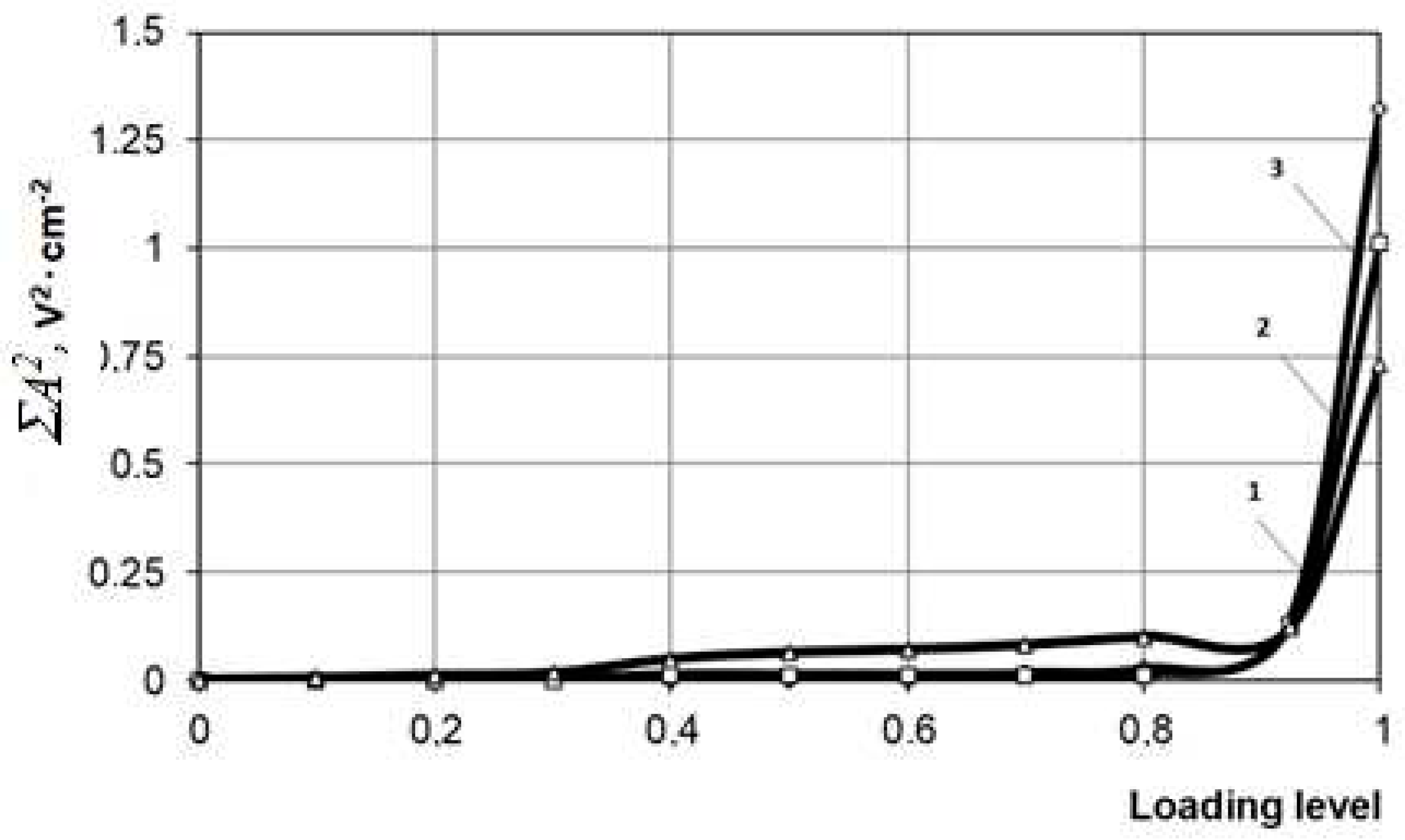
Figure 1 and
Figure 2 show graphical dependences of energy release on the level of loading for a polymer-lime coating after curing. Analysis of the data obtained indicates that an increase in the porosity of the substrate leads to a decrease in the adhesion strength (
Table 1). These data are confirmed by the higher values of the sum of squared amplitudes of acoustic emission signals (energy) released when the coatings are detached from substrates with a lower porosity. So, the value of the sum of squared amplitudes of acoustic emission signals released at a substrate porosity of P = 20% is 1.68 V
2‧cm
-2, and at P = 28% - 0.49 V
2‧cm
-2.
In the process of thermal aging, an increase in the hardness of the coatings is observed, which indicates the occurrence of structure formation processes at this stage of aging.
Thermal aging for 100 h leads to an increase in the strength of both the polymer-lime coating itself and the contact area of the coating with the substrate (
Figure 2 and
Figure 3). This is evidenced by the data on the increase in the value of the energy (the sum of squared amplitudes of acoustic emission signals) released at the last stages of destruction when the coating is torn off. This allows us to talk about the predominance of structure-forming processes over destructive ones at this stage. With an increase in the porosity of the substrate, a significant decrease in the released energy of the AE signals occurs. So, after thermal baking at the substrate porosity P = 20%, the sum of squared amplitudes of acoustic emission signals is 1.88 V
2‧cm
-2, while at P = 28% it is - 0.87 V
2‧cm
-2. In addition, it should be noted that on substrates with high porosity, the release of AE energy occurs at the early stages of loading, which, in our opinion, is explained by a higher concentration of initial defects in the contact zone, which accelerate the fracture process due to a larger plastic zone [
22,
23,
24,
25,
26].
When studying thermal aging, it was recorded that an increase in the thermal aging time leads to a regular increase in the value of the stress intensity factor. For example, after thermal aging of polymer-lime coatings for 100 hours, an increase in the value of the stress intensity factor from K1c=0.044 MN/m1/2 (after curing) to K1c=0.053 MN/m1/2 is observed, and after 200 hours this value is K1c=0.0546 MN/m1/2.
Figure 4 and
Figure 5 show the dependences of the released energy on the loading level for PVAC coatings. The destruction of PVAC coatings after curing is characterized by high values of the released energy at the last stage of loading. But at the same time, the nature of destruction of PVAC coatings is fundamentally different from polymer- lime coatings. With an increase in the porosity of the substrate, an increase in the energy released under the action of the load occurs. In our opinion, this is due to the fact that as a result of the separation of the PVAC coating, the contact zones are involved in the process of destruction. After thermal aging for 100 h, a decrease in the number of AE signals is observed. This indicates that the decrease in the operational resistance of PVAC coatings at this stage of aging is mainly due to destructive processes occurring in the contact zone. So, for example, when the porosity of the substrate is P = 20% the sum of squared amplitudes of acoustic emission signals released at the last stage of loading is 1.38 V
2‧cm
2 after curing, and after heat aging it is 0.99 V
2‧cm
-2. With an increase in the porosity of the substrate, this tendency persists [
27].
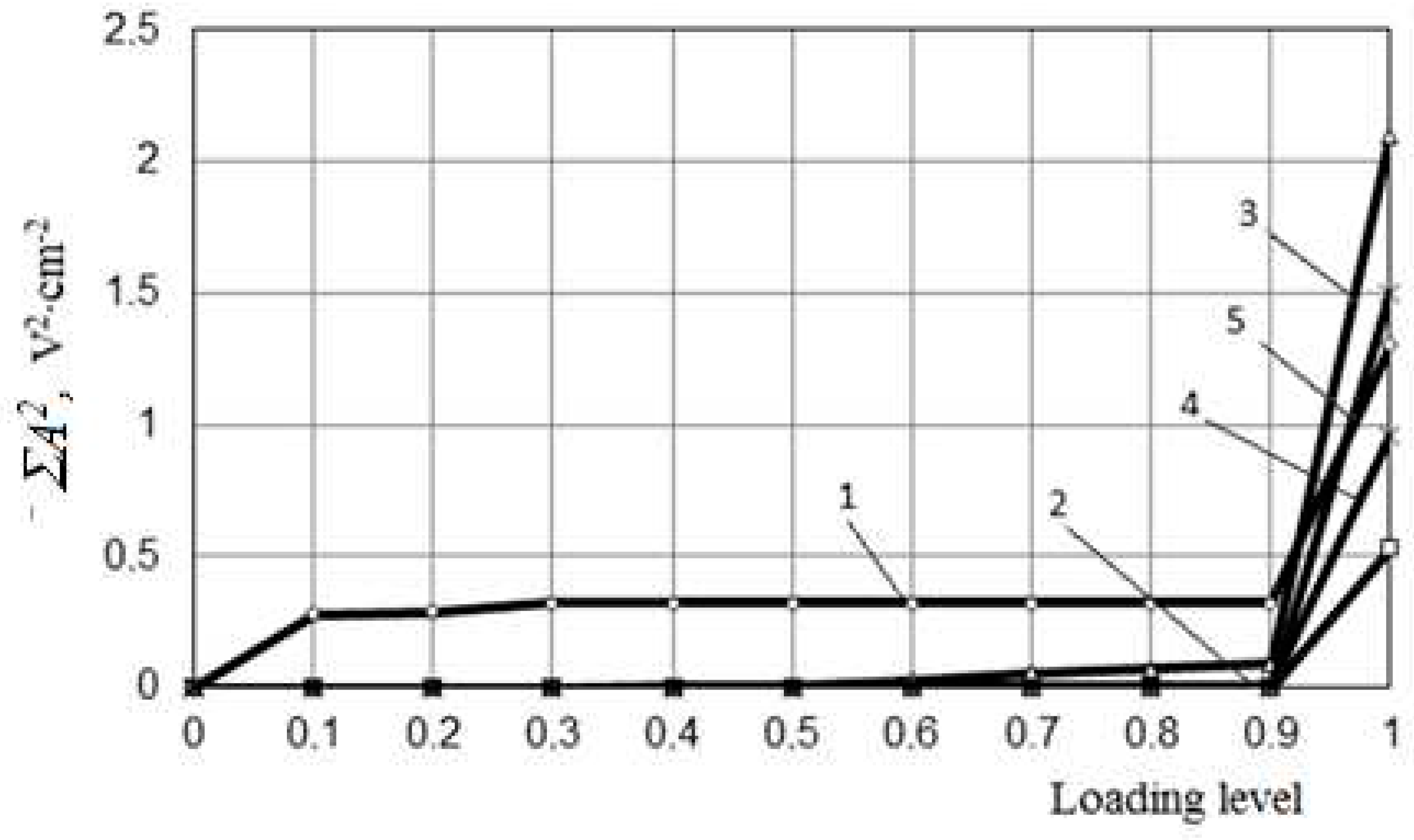
The nature of the destruction of the PF-115 coating is shown in
Figure 6. The test results indicate the presence of a plastic component during the destruction of cured coatings. A sharp decrease in the AE signal energy (sum of squared amplitudes of acoustic emission signals) released during the destruction of coatings on substrates with higher porosity is observed.
The numerical values of the sum of squared amplitudes of acoustic emission signals are significantly lower than the data obtained when testing PVAC and polymer-lime coatings, which indicates the formation of a more defective contact zone. An increase in the porosity of the substrate promotes a higher concentration of defects. After thermal aging for 100 h, an increase in the adhesion strength of the coating is observed. The data obtained indicate an almost complete absence of the plastic component, since there are no pulses at the early stages of loading. Curing of coatings on a substrate with a porosity of P = 24%, previously filled with a composition of oil-glue putty, contributes to the formation of a more uniform structure of the contact layer. Thus, the sum of squared amplitudes of acoustic emission signals upon destruction of PF-115 coatings on a putty substrate is 1.5 V2‧cm-2, while in the absence of a putty it is 0.53 V2‧cm-2.
When assessing the nature of destruction, it was found that for coatings based on polymer-lime and PF-115 paints, after curing, an adhesive type of destruction is characteristic, while for PVAC coatings it is cohesive (by coating). Heat aging basically changes the nature of destruction of PVAC coatings from cohesive to adhesive.
Since the greatest destructive effect on protective and decorative coatings is exerted by their alternating freezing and thawing during operation, it was necessary to assess the degree of influence of such an effect on the adhesion strength of the coating to the substrate.
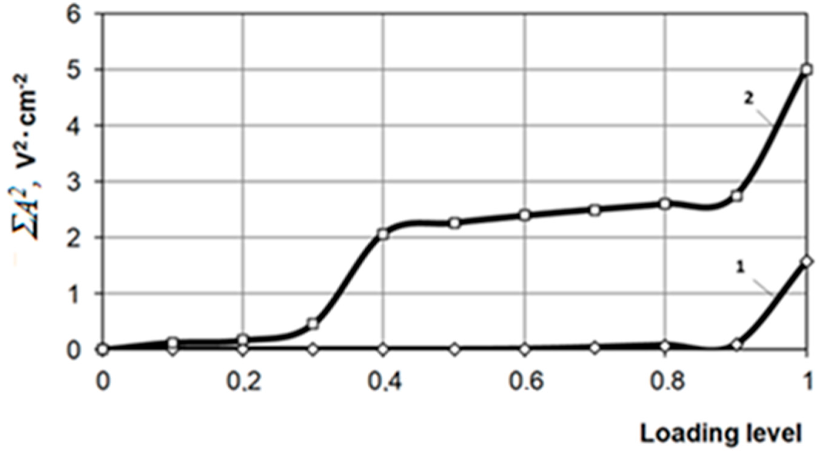
Figure 7 shows the energy release curve for PVAC coating after curing and 15 cycles of alternating freezing and thawing. It should be noted that the release of AE energy for PVAC coatings after 15 cycles of alternating freezing-thawing occurs at the early stages of loading, which, in our opinion, is explained by a higher concentration of defects both in the coating itself and in the contact zone (curve 2).
It was found that in PVAC and polymer-lime coatings on a solution substrate, “embrittlement” occurs after a certain duration of exposure to alternate freezing and thawing. Cracks in the coatings when the Vickers indenter is pressed in appear only after 15–20 test cycles. The value of the critical stress intensity factor of the PVAC coating is K
1c=0.088 MN/m
1/2, and for the polymer lime coating K
1c=0.069 MN/m
1/2 (
Table 2).
PVAC coatings are characterized by an increase in crack resistance with an increase in substrate porosity from 20% to 26%. The critical value of the stress intensity factor for PVAC coatings with a substrate porosity of 20% is K1c=0.088 MN/m3/2. At the same time, the appearance of cracks in the coating during the introduction of the Vickers indenter was recorded after 11 cycles of alternating freeze-thaw. At a substrate porosity of 26%, the appearance of cracks is observed only after 15 cycles of alternating freeze-thaw. Preliminary preparation of the substrate surface has a significant effect on the crack resistance of protective and decorative coatings. For example, priming the substrate surface leads to an increase in the crack resistance of coatings. At the same time, the appearance of cracks when the Vickers indenter was pressed into the PVAC coating on a substrate with porosity P=20% was observed after 15 cycles of alternate freezing-thawing. Puttying the surface before painting in order to reduce the porosity of the substrate leads to an increase in the crack resistance of the coating. Thus, the stress intensity factor of the acrylate coating deposited on the surface of the substrate after its preliminary preparation was K1c=0.023 MN/m3/2, while without preparation it was K1c=0.056 MN/m3/2. The results obtained indicate that the high porosity of the substrate leads to the formation of an inhomogeneous, more defective coating structure, characterized by the formation of cracks at an earlier stage of aging. This is also evidenced by acoustic emission data.
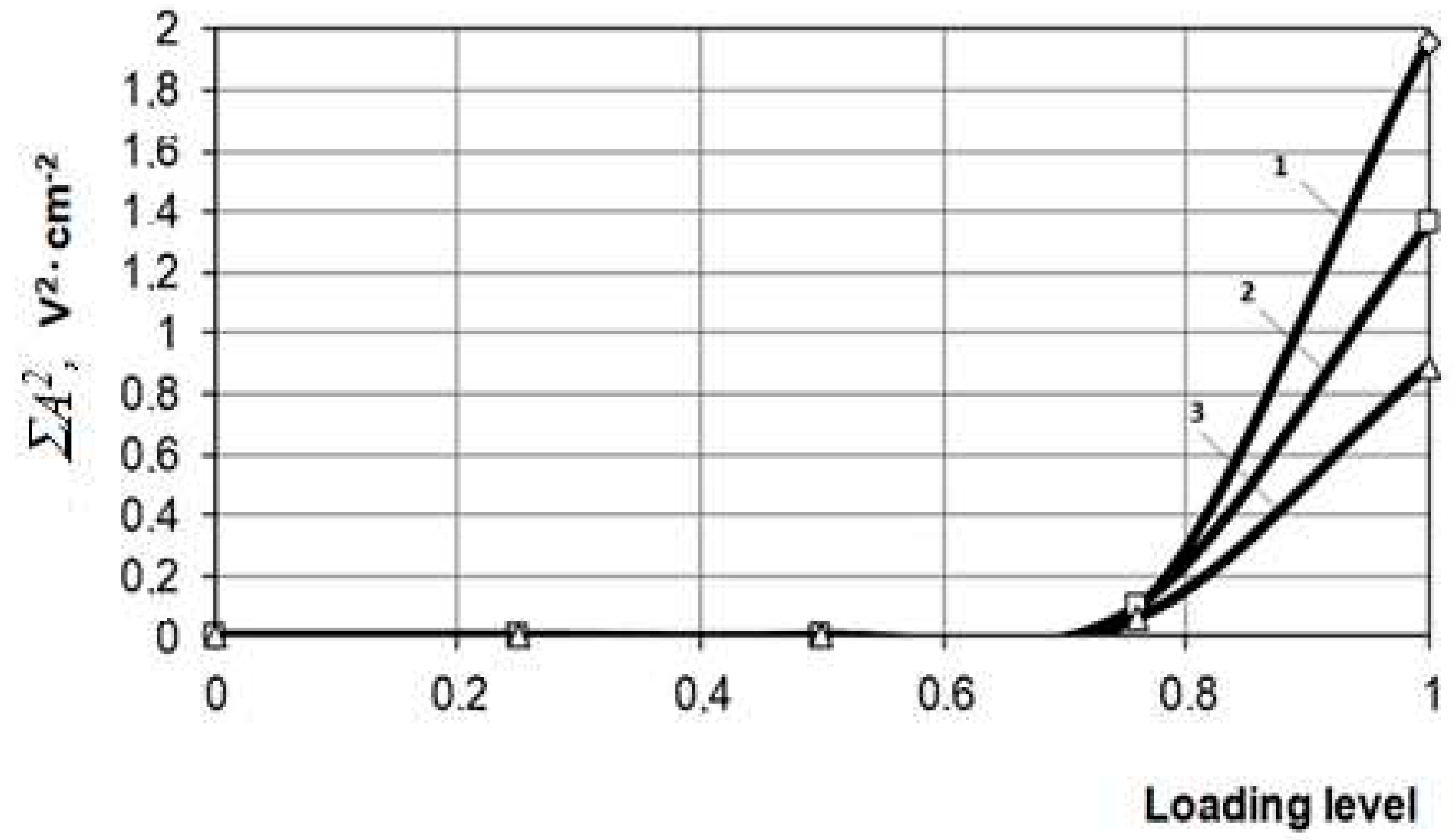
Figure 8 shows the energy release curve for acrylate after curing, 15 and 25 cycles of alternating freezing and thawing. Analysis of the results indicates that alternating freezing-thawing has the greatest destructive effect on the contact area of the coating with the substrate. With an increase in the cycles of alternating freezing-thawing, the amount of energy released at the last stage of loading decreases. So, after curing, the sum of squared amplitudes of acoustic emission signals is
= 1.96 V
2‧cm
-2, after 15 cycles of alternating freezing-thawing
= 1.36 V
2‧cm
-2, and after 25 cycles of alternating freezing-thawing
= 0.89 V
2‧cm
-2. In addition, it should be noted that the nature of the destruction in all considered cases was adhesive.
4. Conclusions
Thus, the application of the method of acoustic emission makes it possible to assess the nature and kinetics of destruction of coatings of cement concretes and to give a comparative quantitative assessment of the resistance of coatings based on the information of acoustic energy of destruction. The methodological approach used in the work, in our opinion, makes it possible to optimize the compositions of protective and decorative coatings, to predict the resistance of coatings in order to obtain coatings with a set of specified properties.
Author Contributions
Conceptualization, V.I.Loganina. and L.V.Makarova.; methodology, K.A.Sergeeva.;. formal analysis, V.I.Loganina.; investigation, X.X.; resources, X.X.; data curation, X.X.; writ-ing—original draft preparation, X.X.; writing—review and editing,V.I.Loganina.; visualization, L.V.Makarova.; su-pervision, K.A.Sergeeva.;;. All authors have read and agreed to the published version of the manuscript.
Funding
The funders had no role in the design of the study; in the collection, analyses, or interpretation of data; in the writing of the manuscript; or in the decision to publish the results”. “Written informed consent has been obtained from the patient(s) to publish this paper”
Conflicts of Interest
The authors declare no conflict of interest.
References
- Loganina, V.; Fediuk, R.; Taranov, D.; Amran, H.M. Estimation of the probability of cracking of facade coatings. Materials Science Forum 2021, 1037, 675–683. [Google Scholar] [CrossRef]
- Loganina, V.; Skachkov, J. Assessment of the stress state of the coating in depending on the porosity of the cement substrate. Key Engineering Materials 2017, 737, 179–183. [Google Scholar] [CrossRef]
- Bansal, P.; Shipway, P.H.; Leen, S.B. Finite element modelling of the fracture behaviour of brittle coatings. Surf. Coat. Technol. 2006, 200, 5318–5327. [Google Scholar] [CrossRef]
- Shneiderova, V.V. Anti-corrosion coatings; Stroyizdat: Moscow, 1982; 132p. [Google Scholar]
- Strength and crack resistance of structural building materials under complex stress state: Monograph; under total scientific ed. S.N. Leonovich. Minsk: BNTU, 2013, 522p.
- Boldyrev, G.; Guskov, I.; Lavrov, S.; Sidorchuk, V.; Skopintsev, D. Comparison of soil test data, obtained with different probes. Proceedings8.of the 3-d International Conference on the Flat Dilatometer. 2015, Vol. 3. https://www.marchetti-dmt.it/conference/dmt15/papers%20DMT%202015%20(pdf)/17.pdf.
- Boldyrev, G.G.; Melnikov, A.V.; Barvashov, V.A. Particle image velocimetry and numeric analysis of sand deformations under a test plate Proceedings of the 5-th European Geosynthetics Congress 2012, Vol. 1, 685–691: https://www.researchgate.net/publication/291327640.
- Zang, A.; Wagner, F.; Stanchits, S.; Dresen, G.; Andresen, R.; Haidekker, M. Source analysis of acoustic emissions in Aue granite cores under symmetric and asymmetric compressive loads. Geophys. J. Int. 1998, 135, 1113–1130. [Google Scholar] [CrossRef]
- Ono, K. Application Of Acoustic Emission For Structure Diagnosis. Diagnostyka - diagnostics and structural health monitoring 2010, 2, 3–18. [Google Scholar]
- Ohtsu, M.; Isoda, T.; Tomoda, Y. Acoustic emission techniques standardized for concrete structures. J. Acoustic Emission 2007, 25, 21–32. [Google Scholar]
- Petersen, T.V.; Shemyakin, V.; Chernigovsky, V. Noise diagnostics at AE monitoring of hazardous industrial asset. Advances in Acoustic Emission Technology. Proceedings of the of the World Conference on Acoustic Emission 2013, 93–102. [Google Scholar] [CrossRef]
- Lobanov, D.; Zubova, E. Research of temperature aging effects on mechanical behaviour and properties of composite material by tensile tests with used system of registration acoustic emission signal. Procedia Structural Integrity 2019, 8, 347–352. [Google Scholar] [CrossRef]
- Nosov, V. Principles of optimization of acoustic emission control technologies industrial facilities. Defectoscopy 2016, 7, 52–67. [Google Scholar] [CrossRef]
- Nosov, V. On the principles of optimization of acoustic emission control technologies strength of industrial facilities. Russian Journal of Nondestructive Testing 2016, 52, 386–399. [Google Scholar] [CrossRef]
- Agletdinov, E.; Vinogradov, A.; Merson, D. Applied Science 2020, 10, 73. [CrossRef]
- Gomera, V.P.; Smirnov, A.D.; Nefediev, E.Y.; et al. Detection of cracks in a welded seam by acoustic emission method during welding. Kontrol. Diagnostics 2016, 7, 25–32. [Google Scholar] [CrossRef]
- Botvina, L.; Soldatenkov, A.; Levin, V.; Tyutin, M.; Demina, Y.; Petersen, T.; Dubov, A.; Semashko, N. Assessment of the characteristics of damage to low-carbon steel by physical methods. Metals 2016, 1, 27–39. [Google Scholar]
- ISO 16836:2019 Non-destructive testing -- Acoustic emission testing -- Measurement method for acoustic emission signals in concrete. (http://files.stroyinf.ru/Data/769/76924.pdf).
- ISO 16837:2019 Non-destructive testing -- Acoustic emission testing -- Test method for damage qualification of reinforced concrete beams. (http://files.stroyinf.ru/Data/769/76924.pdf).
- ISO 16838:2019 Non-destructive testing -- Acoustic emission testing -- Test method for classification of active cracks in concrete structures. (http://files.stroyinf.ru/Data/769/76924.pdf).
- Loganina, V.I.; Makarova, L.V. To the method for assessing the crack resistance of protective decorative coatings. Plasticheskie Massy: Sintez Svojstva Pererabotka Primenenie 2003, 4, 43–45, (http:www.plastics-news.ru). [Google Scholar]
- Grosse, C.; Ohtsu, M. (Eds.) Acoustic emission testing; Springer; p. 2008. [CrossRef]
- Ohtsu, M.; Uchida, M.; Okamoto, T.; Yuyama, S. Damage assessment of reinforced concrete beams qualified by acoustic emission. ACI Structural Journal 2022, 99, 411–417, (http:www.structurae.net). [Google Scholar]
- Zubova, E.; Strungar, E.; Lobanov, D.; Wildemann, V.E. Experimental study of the damage accumulation in composite materials and ceramic coatings by using of acoustic emission technique. Procedia Structural Integrity 2019, 17, 822–827. [Google Scholar] [CrossRef]
- Bataronov, I.; Dezhin, V.J. J. Phys. Conf. Ser. 2019, 1203, 012060. [CrossRef]
- Shibkov, A.; Zheltov, M.; Gasanov, M. Mater. Sci. Eng. A 2020, 772, 138777. [CrossRef]
- Loganina, V.I.; Makarova, L.V. Technique of the Assessment of Crack Resistance of the Protective Decorative Coatings. Contemporary Engineering Sciences 2014, 7, 1967–1973. [Google Scholar] [CrossRef]
|
Disclaimer/Publisher’s Note: The statements, opinions and data contained in all publications are solely those of the individual author(s) and contributor(s) and not of MDPI and/or the editor(s). MDPI and/or the editor(s) disclaim responsibility for any injury to people or property resulting from any ideas, methods, instructions or products referred to in the content. |
© 2023 by the authors. Licensee MDPI, Basel, Switzerland. This article is an open access article distributed under the terms and conditions of the Creative Commons Attribution (CC BY) license (http://creativecommons.org/licenses/by/4.0/).
