1. Introduction
In the 1950s, the Worms Bridge with a span of 114.2m was built by the balanced cantilever method in Germany. Since then the concrete box girder was widely used in long-span bridges [1].
The deflection histories of more than 60 bridges are collected by Bazant [2] which shows the phenomenon of excessive long-time deflection is common. The failure of the Koror-Babeldaob (KB) Bridge attracted so many scholars to dig for the truth after the detailed technical data was released in 2008 [3]. Burgoyne and Scantlebury tried to exhaust the likely cause such as geometry, remediation, analysis, potential damage, and so on; yet no satisfactory explanation was discovered [4]. The time-dependent factor (creep and shrinkage) was the most suspicious reason, researchers focus their attention on this field [5–7]. In recent years the focus of the research has shifted to calculation methods [8–11].
The KB Bridge with a span of 240.79m was first opened to traffic in April 1977; the repair work was completed in July 1996; the bridge collapsed in the afternoon on 26 September 1996 [12]. Before the reparation, the deflection of the bridge had reached 1.54m at the span center. Two firms (JICA from Japan and ABAM from the US) were hired to investigate the unexplainable excessive deflection. Both firms came to the conclusion that the bridge was structurally safe, which made the repair work of turning the cantilever structure into a continuous structure a very suspicious reason for the failure. Therefore, the process of stress redistribution which is also a time-dependent factor has never been discussed.
This study aims to enhance the understanding of the process of stress redistribution due to the change of geometric boundary conditions. The virtual stiffness method is created to visualize and analyze the process. A new theory which I called Material Inelasticity and Prestress Loss Coupling Effect is presented and discussed.
2. Question of Stress Redistribution
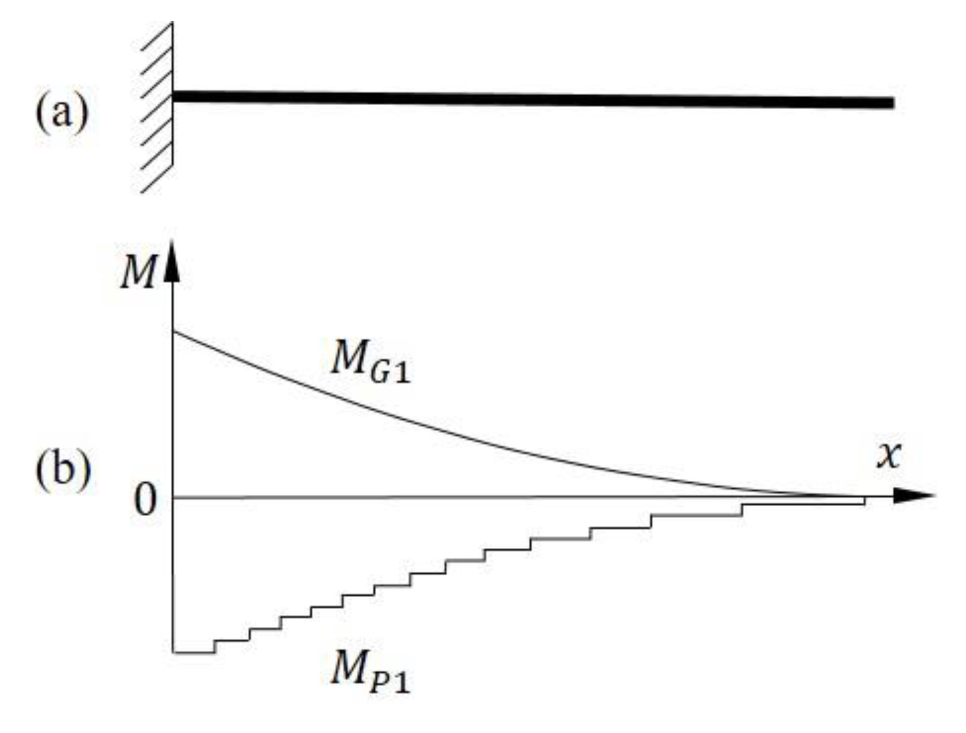
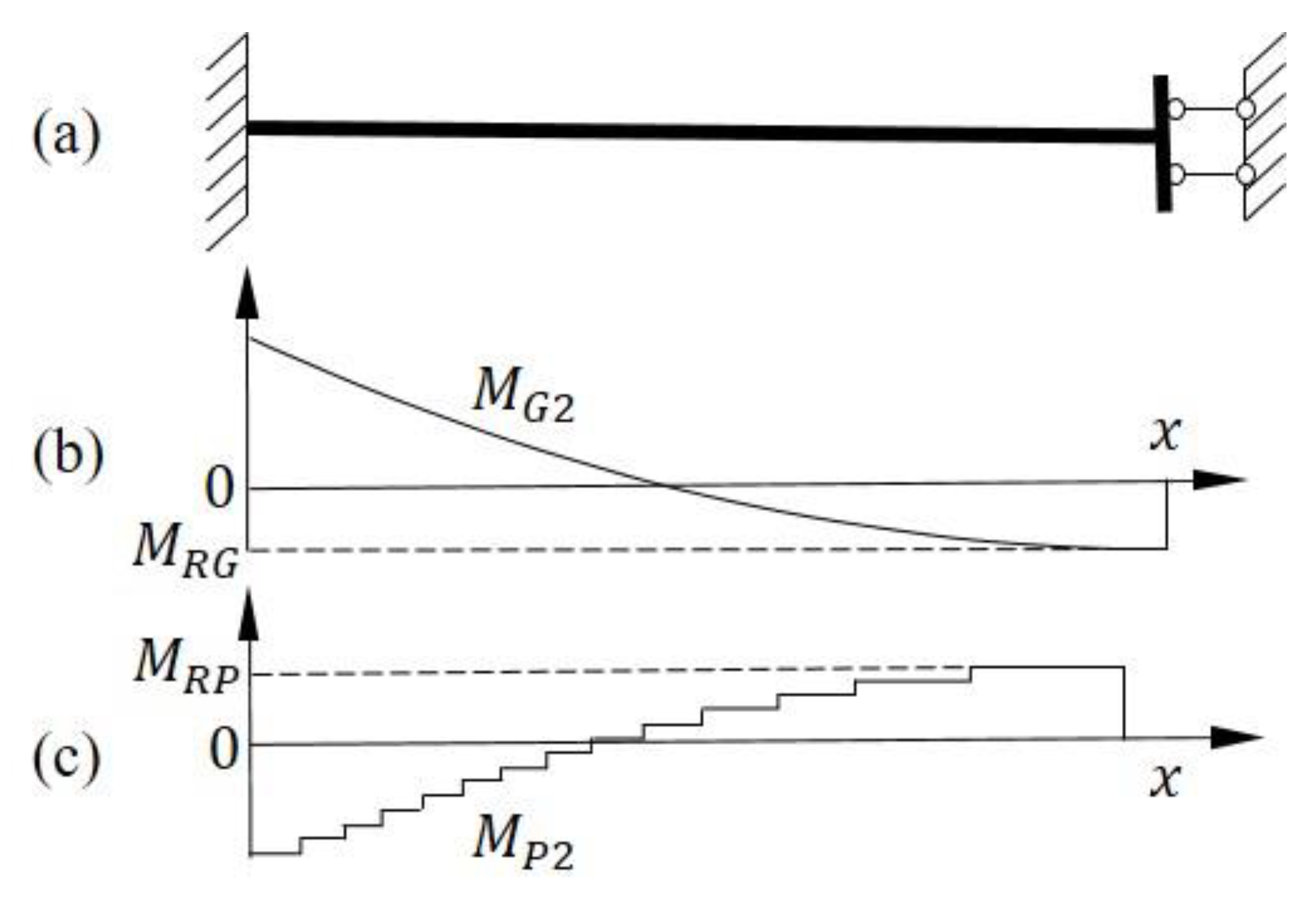
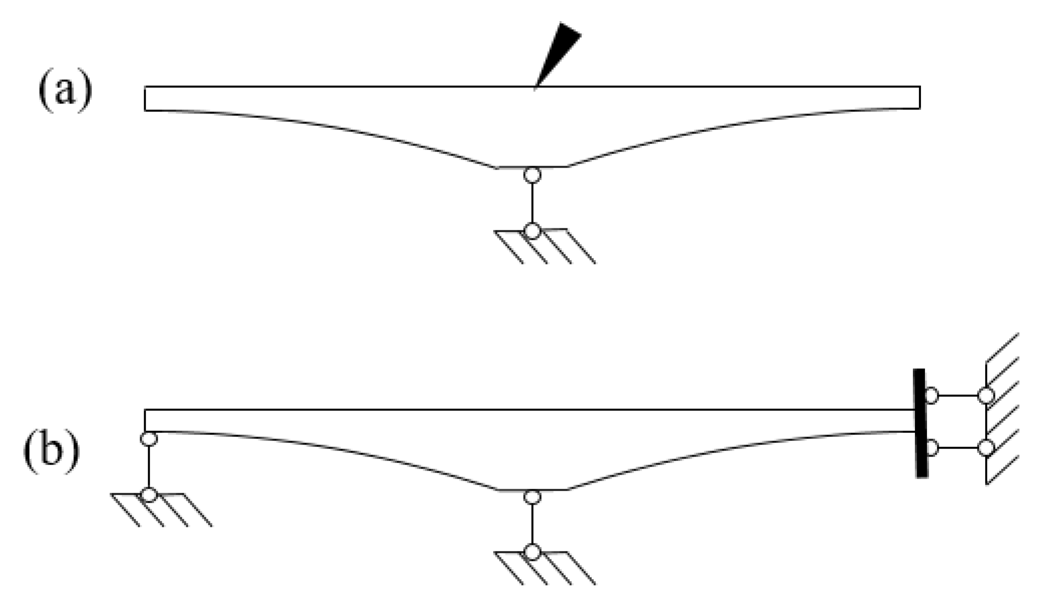
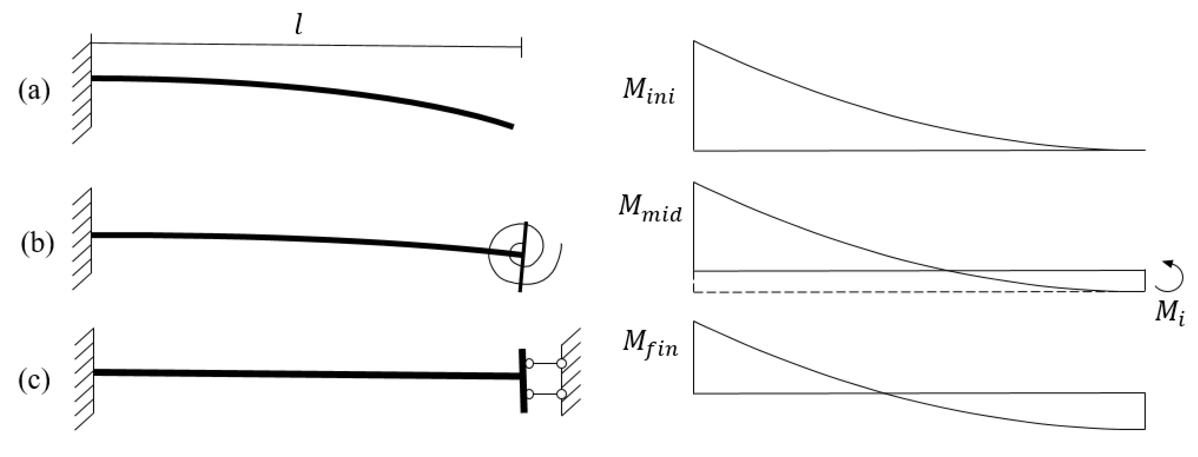
The deflection and boundary condition of system transformation is shown in
Figure 1(a) and
Figure 2(a). In the load-balancing method, the moment caused by gravity (
) is roughly equal to the moment caused by prestress (
), but the direction is opposite. The positive bending moment indicates that the upper edge is in tensile stress.
The dashed line in
Figure 2(b) represents the redistribution moment (
MRG) acting on the gravity effect, the moment caused by gravity(
) after the alteration may be calculated from
There is no external force involved during the process of the moment redistribution, then the redistribution moment ()acting on the prestress effect may be taken as
The moment caused by prestress() after the alteration is shown that
It is shown in
Figure 2(c) that
is positive which means the prestress effect after the alteration caused the tensile stress on the upper edge around the mid-span. The conclusion is wrong, but it is hard to find the problem in force analysis.
The essence of moment redistribution is the stain energy variation; the methodology needs to be related to the principle of minimum potential energy.
3. Virtual Stiffness Method
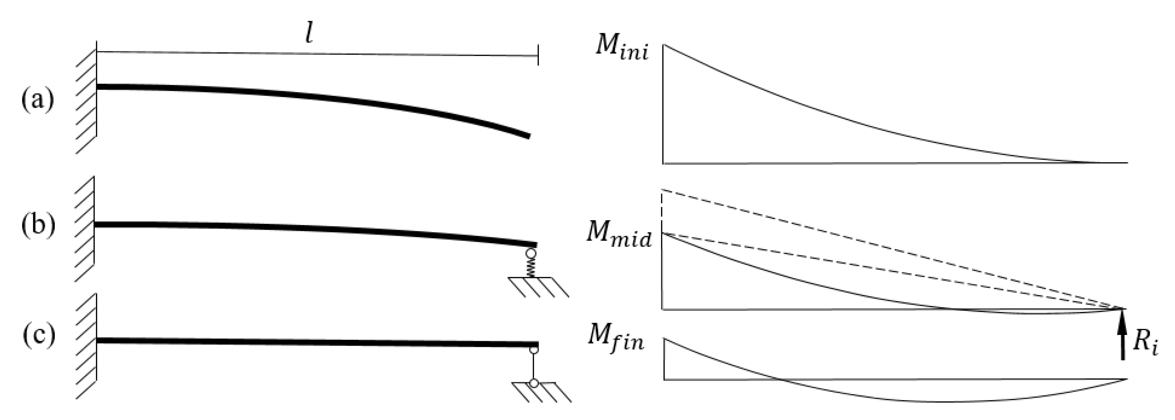
The cantilever beam model with an excessive vertical bearing was shown in
Figure 1. The boundary condition change from
Figure 3. (a)to (c) can be replaced equivalently by
Figure 3. (b) which is supported by a spring. The stiffness of the spring varied from 0 to ∞.
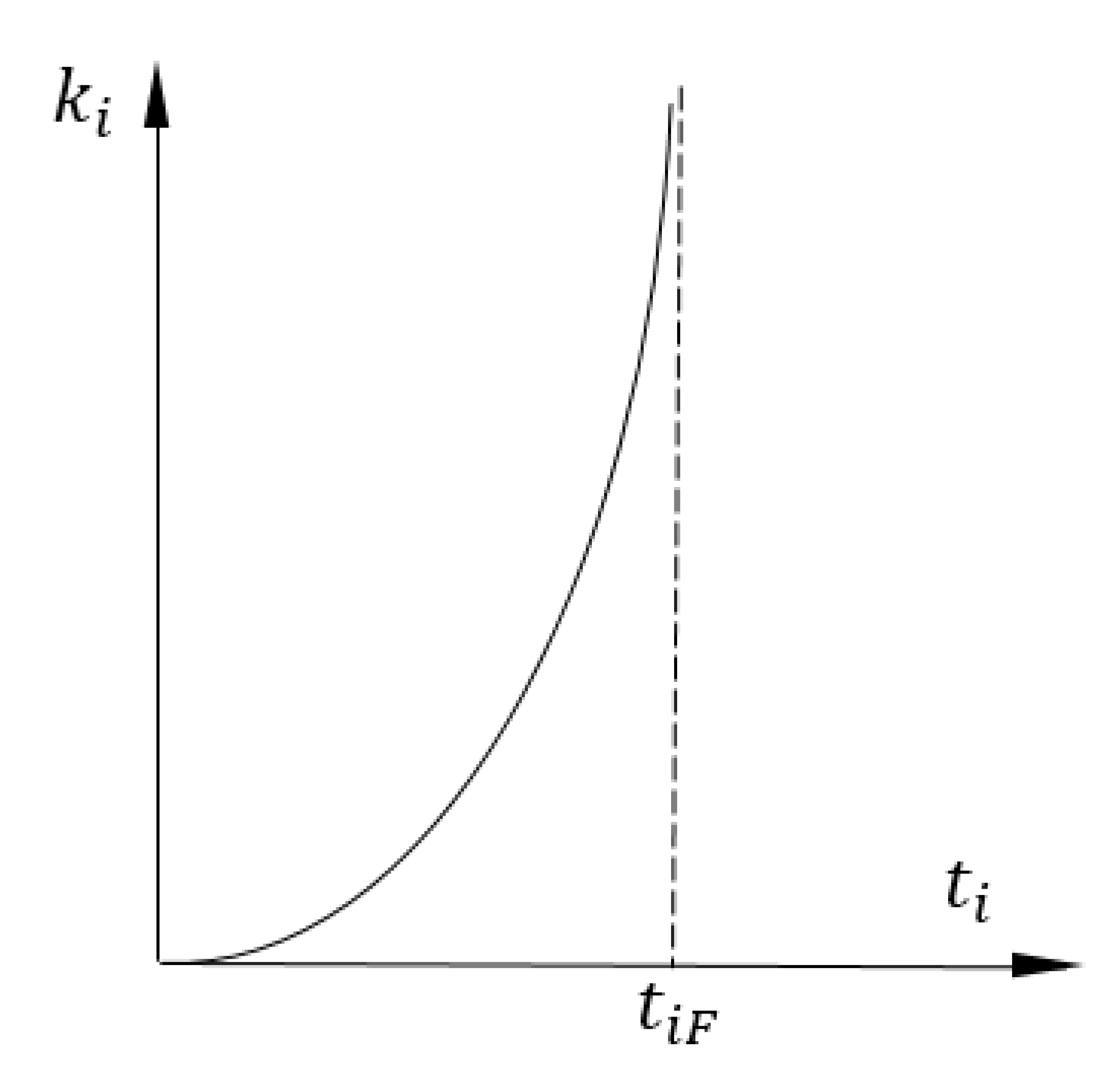
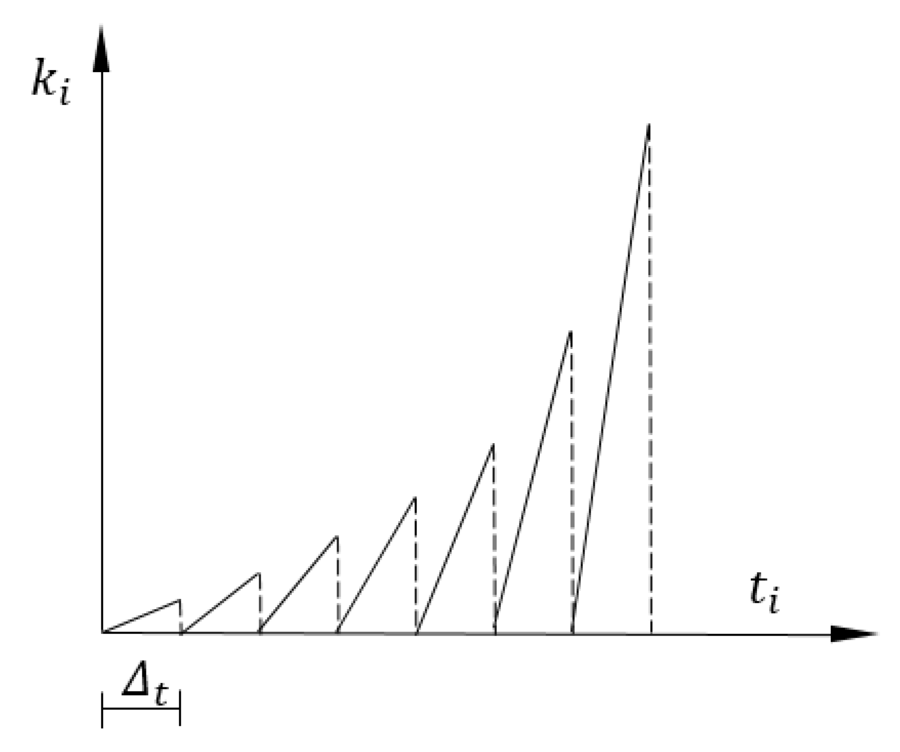
The curve of an assumed stiffness function is shown in
Figure 4, where the independent variable is time. The stiffness is named
and the variable is named
, since the function of stiffness is imaginary.
Here are some basic characteristics of the bearing:
- (1)
The bearing can only provide passive force.
- (2)
The bearing cannot impose an action that the structure cannot resist (e.g., the compression on the rope).
Why does the function
equal the change of the boundary condition? At the beginning when
is 0, the beam has no restriction at the ending and the beam deflects freely; when
reaches to ∞, there is no displacement at the point of spring. The process of the stiffness change does not have to be a smooth concave function, the curve in
Figure 4 is just an assumed function. During the whole process, the spring supplies the passive force rather than the active force which fits the basic characteristics of the bearing.
Based on the Euler-Bernoulli theorem, the deformation which is caused by shear force can be neglected on the slender rod. Eq.(5) can calculate the cantilever beam’s strain energy.
The direction of the passive force is always opposite to the direction of the displacement of the spring which means the spring cannot increase the strain energy of the cantilever beam.
The dotted triangle in
Figure 1(b) represents the moment that is caused by the bearing force. As the imaginary stiffness gets bigger the passive force of the spring and dotted triangle gets bigger. Finally, the strain energy reaches the minimum.
If
equals 1(no unit), the dimension of
in Eq.(5) is the same as the displacement; if
equals 1 (no unit), the dimension of
is the same as the moment. Those are the basic ideas of the virtual force and displacement methods. If the spring and the beam
Figure 3(b) are considered a conservative system of energy. While the energy of the system(
) is constant,
is variant for
, then
can be calculated by
.
refers to the spring deformation energy, When the boundary condition changes to a rotational spring, the
in
Figure 3(b) is replaced by
.
Eq. (7) is the expression of the virtual stiffness method, the strain energy is calculated by the stiffness of the bearing which is the function of time.
4. The System Transformation of Continuous Concrete Beam
4.1. The initial energy
Boundary conditions of the continuous concrete beam are shown in
Figure 5. From the viewpoint of the energy, the strain energy is transformed from the work of gravity and prestress tendon. The effect of energy is not related to the process. The initial state of the system’s strain energy(
) consists of strain energy caused by gravity(
) and strain energy caused by the tendon (
).
According to the principle of minimum potential energy, after the redistribution of the moment, the energy of the system reaches the minimum.
4.2. The Calculations on the moment redistribution
In the real model, the cross-sections of the cantilever beam varied, and the moment of inertia in Eq. (5) is not constant. The integral in Eq. (5) can be solved by adding up the strain energy of small segments in numerical analysis. The rule of the internal force variation is our main concern, so the precondition of a uniform beam is proposed.
4.2.1. The gravity part
The moment(
) caused by the imaginary stiffness of the rotational bearing is shown in
Figure 6(b). The strain energy is reduced to the minimum which means the first derivative of
of
equals 0.
The imaginary resistance force(
) of the bearing from
Figure 3(b) can be deduced as follows:
After the imaginary moment(
) and imaginary resistance force(
) are calculated, the unbalanced moment of the fixed ending in
Figure 6 and
Figure 3 can be calculated by the moment distribution method or virtual displacement method, which is not shown in this paper.
The stress redistribution caused by moment redistribution can be calculated by plane section assumption.
4.2.2. The prestress tendon part
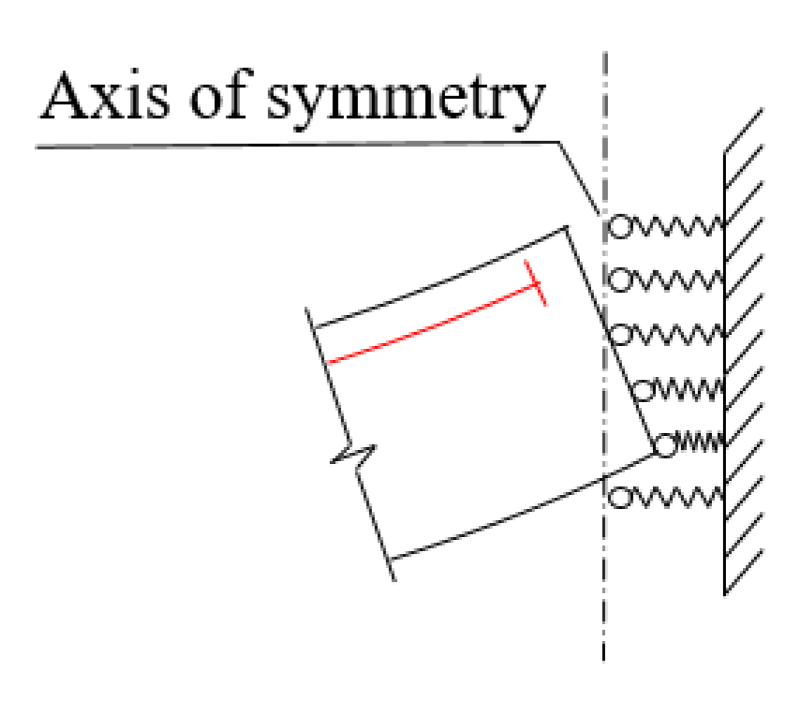
The stress redistribution of prestress tendon cannot be calculated the same as the stress redistribution of gravity. Because the upper part of the fiber is compressed under the load of prestress tendon. The passive bearing cannot elongate the upper part of the fibber. The boundary condition is simulated by a series of springs (
Figure 7) rather than a rotational bearing during the process of system transformation. The curve of the imaginary stiffness of the springs is applied and shown in
Figure 8.
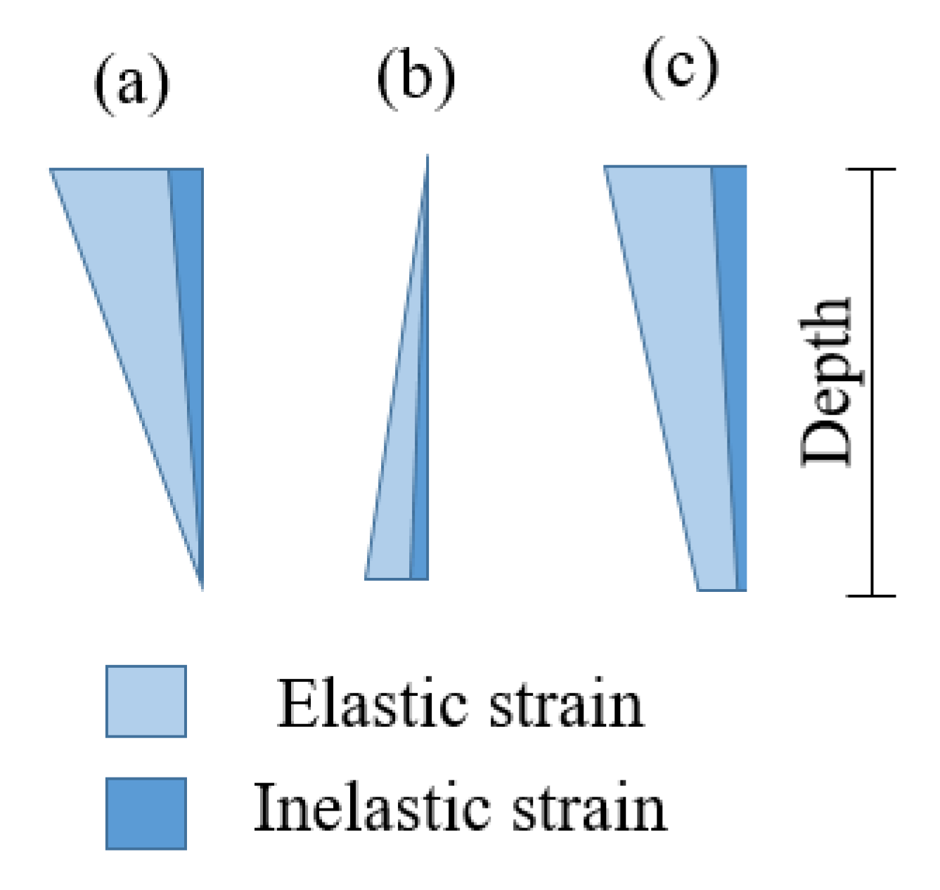
The strain caused by prestress tendon is shown in
Figure 9(a); the strain caused by bearing is shown in
Figure 9(b). Total strain(
Figure 9(c)) is combined by (a) and (b). The magnitude along the depth of the beam does not have to be linear. The inelastic deformation accumulates under cycled load since the sum of inelastic strain is positive in each iteration time (
).
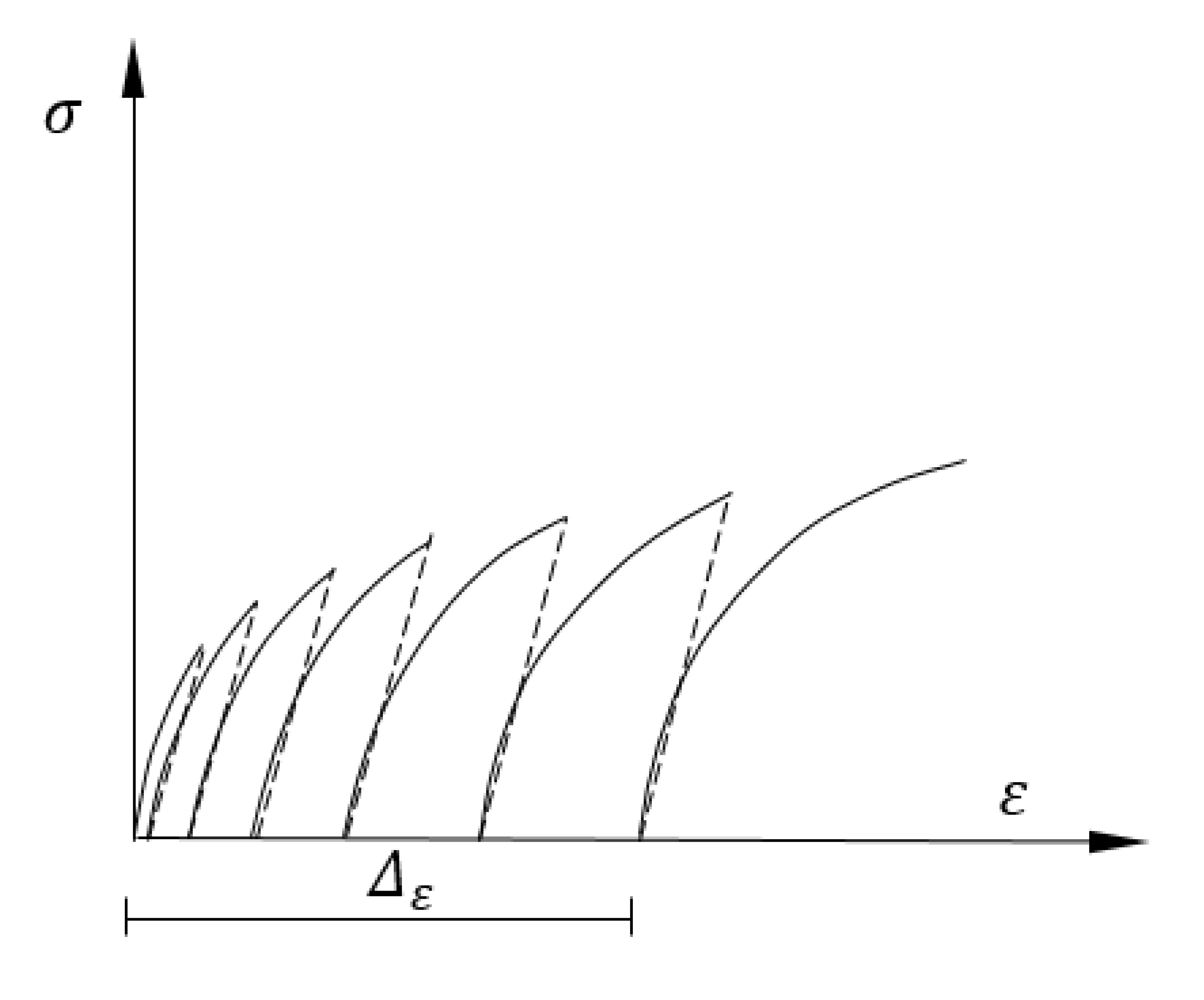
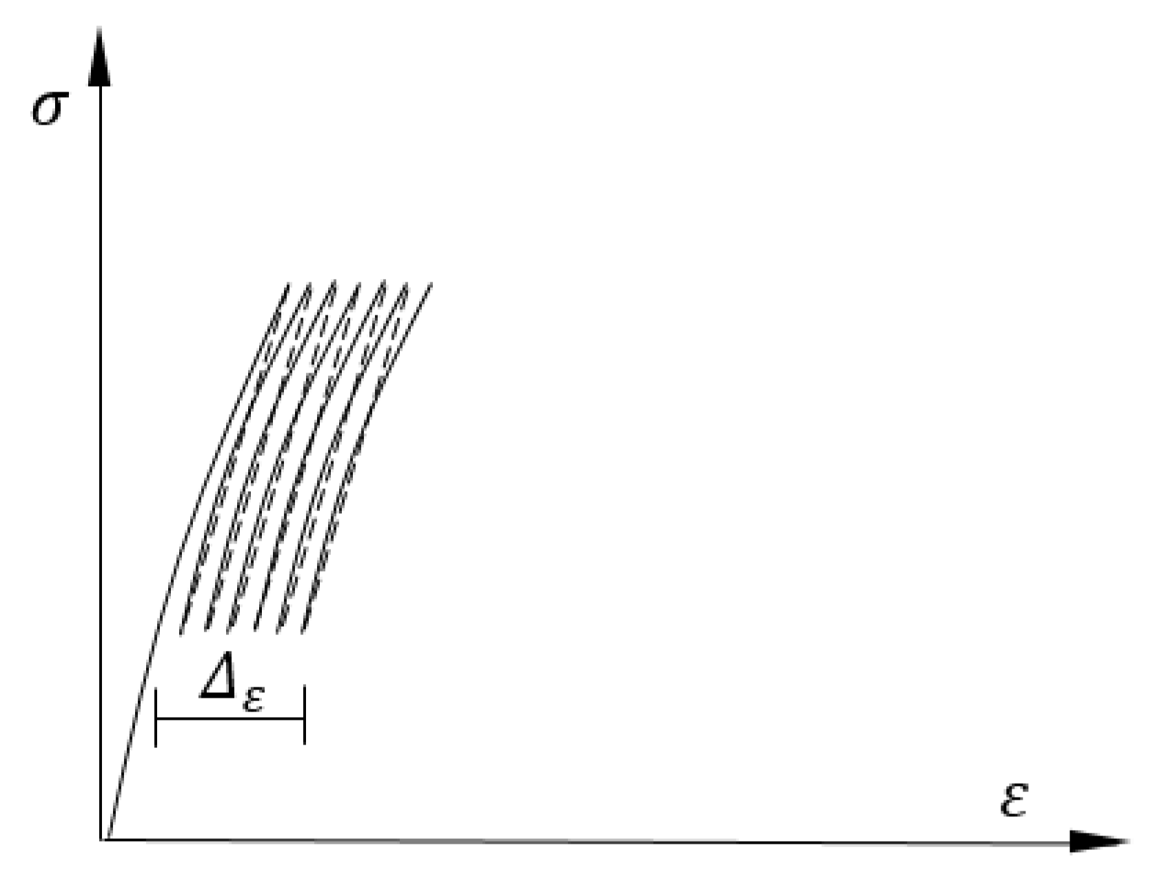
The stress-strain property during the cycled reaction force derived from the imaginary stiffness of the bearing is shown in
Figure 8. The whole depth of the beam has inelastic strain(
)which means inelastic deformation of the beam. The prestress force of the tendon tends to decrease as the shortage of beam in the longitudinal direction. The time in virtual stiffness is imaginary, then the cycle load can be imposed instantaneously. But the inelastic deformation requires time. The inelastic property can be comprehended by creep theory in which the deformation is due to the viscous flow and slip of the gel. The inelastic strain(
) in
Figure 10 is the additional deformation of boundary conditions, with the viscous flow and the slip of the gel it occurs like long-term action.
The inelastic deformation and prestress loss coupled with each other which I called Material Inelasticity and Prestress Loss Coupling Effect. The coupling effect might be the key to long-term excessive deflections in segmental concrete bridges.
4.3. Final state of the energy
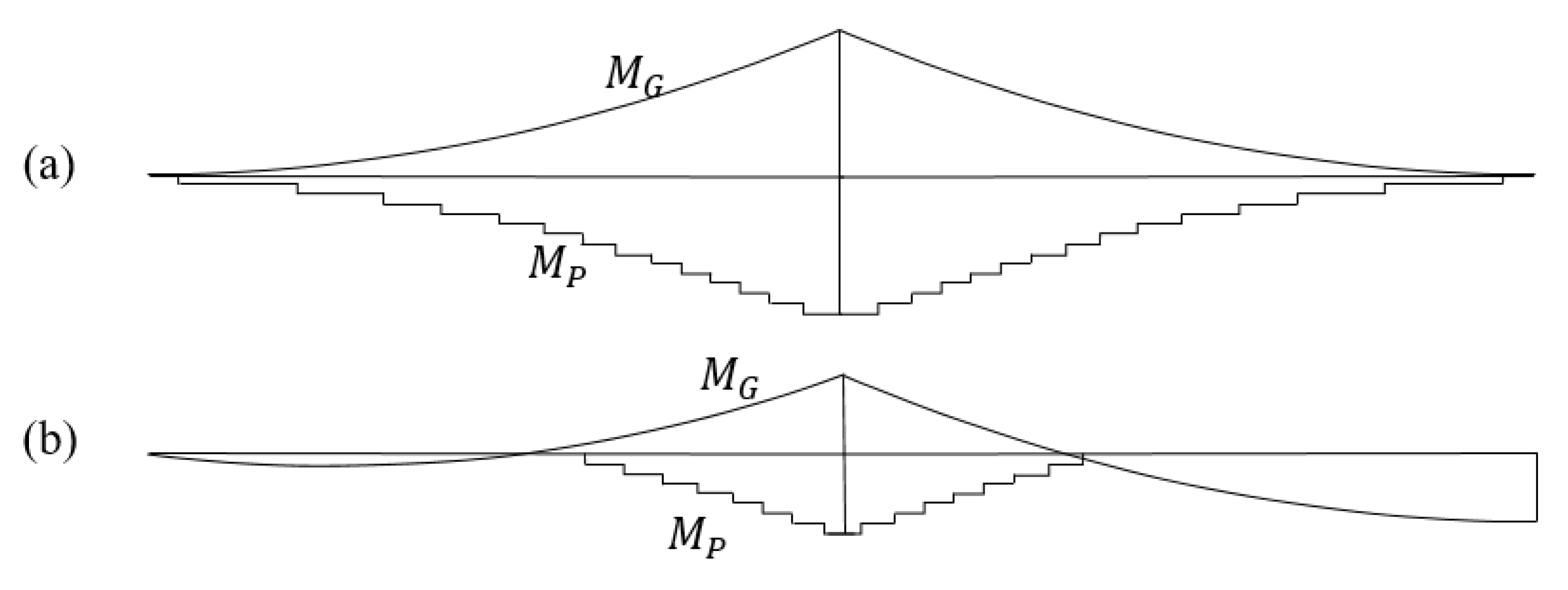
After the inelastic deformation of the beam and the prestress loss in the tendon, the moment caused by prestress disappeared in the middle span. As the coupling effect proceeds the moment of the continuous beam lies somewhere between
Figure 11 (a) and (b).
5. The Coupling Effect in Cantilever Beam
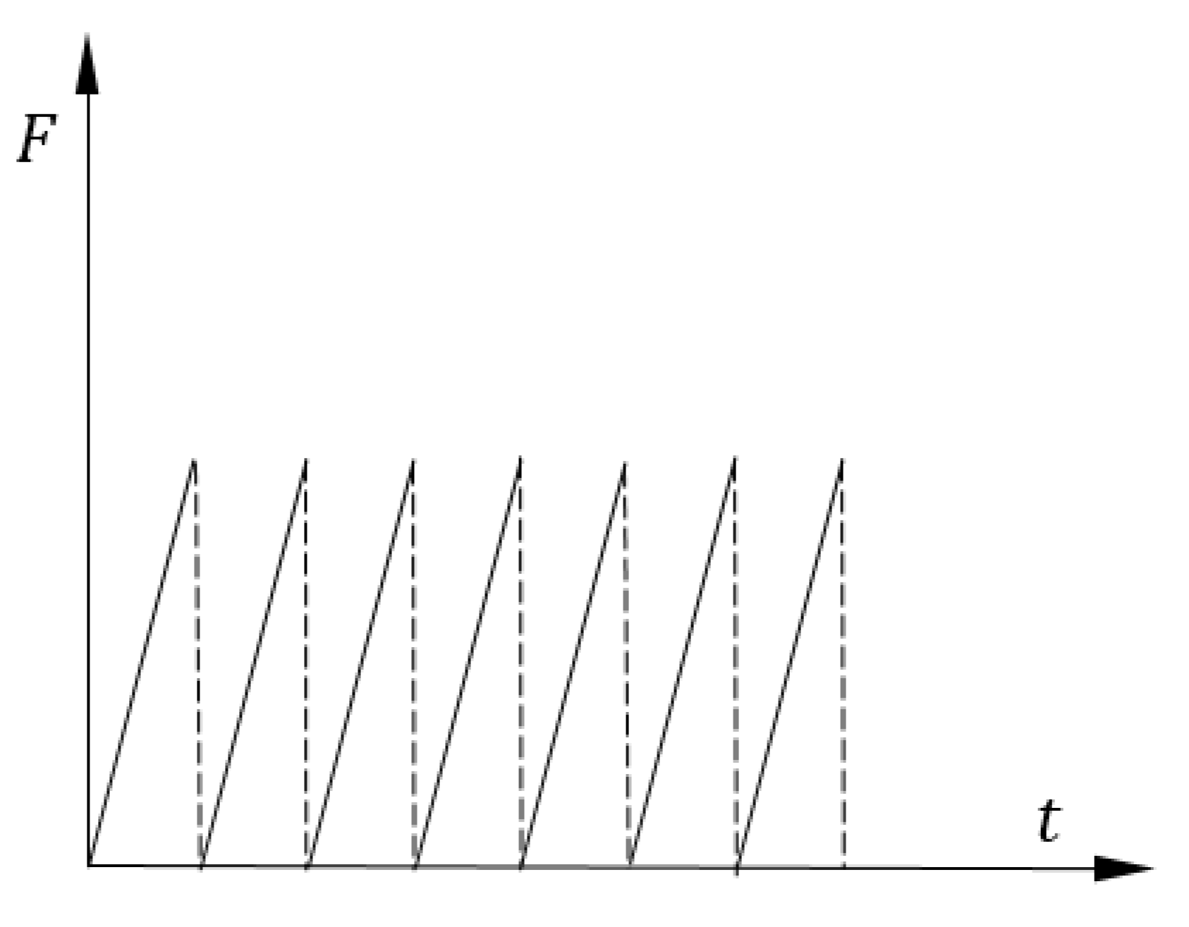
In the cantilever beam, there is still a coupling effect caused by the live load. The service load can be simulated by pulsating load at the span center shown in
Figure 12. The lower part of the beam has elastic strain due to the living load. The stress-strain property is shown in
Figure 13. The accumulation of the inelastic strain during live load can be found as
.
6. Calculation of Excessive Deflection
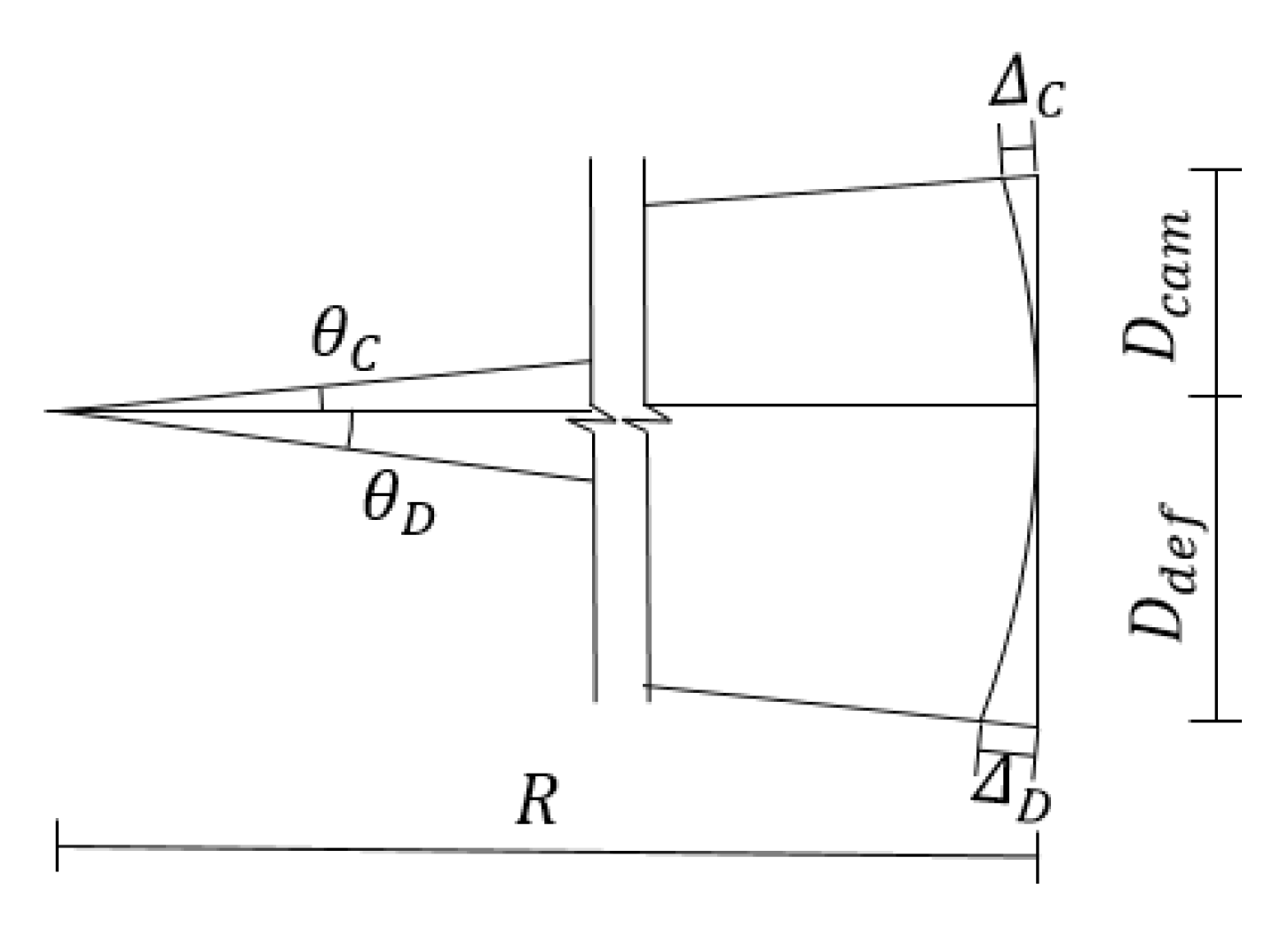
A macroscopic view of the relationship between longitudinal length reduction and vertical deflection is presented in
Figure 14. The deflection curve along the longitudinal direction is hard to simulate but a simple model of assumed radius (
) could explain the principle.
Material Inelasticity and Prestress Loss Coupling Effect is the inherent nature of material and geometry. means the shortage of the beam and means the elongation of the beam.
The average inelastic strain (
) is calculated from Eq.(19) where
is the inelastic strain in each section of the beam. The function
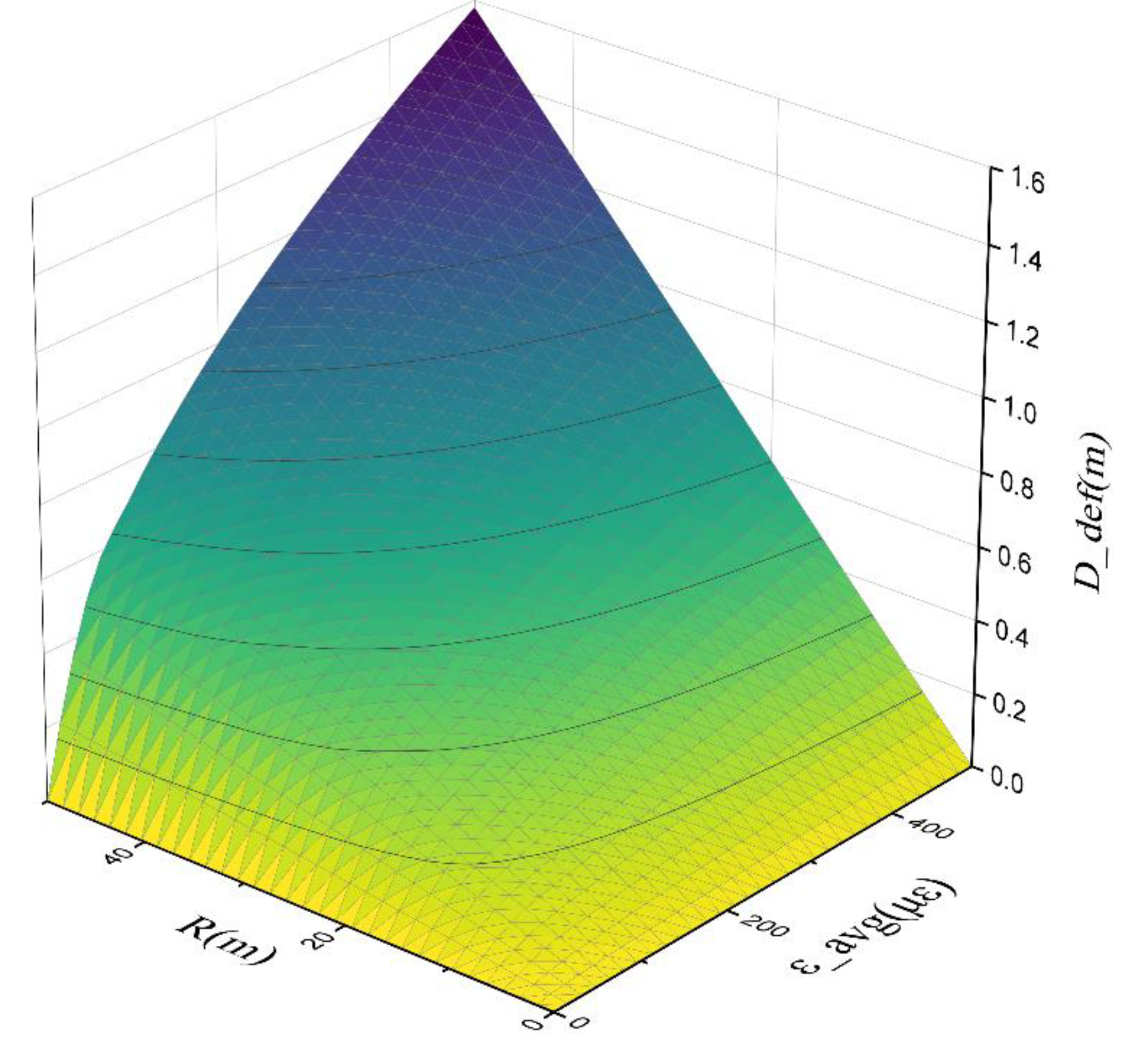
is plotted in
Figure 15, where
equals 50m, and
equals 500
, the excessive deflection could reach 1.58m. The excessive deflection and the shear resistance of the beam may interact with each other which is the deterioration effect [13]. Which will lead to extra cracking.
7. Discussion and Suggestions on Design and Construction
7.1. Design
As shown in Eq. (6), The process of stress redistribution is the process of energy transmission. It is also a process of energy dissipation due to the discovery of Material Inelasticity and Prestress Loss Coupling Effect. It requires vibration and deformation to let the energy flow. The bottom prestress tendon (after the closure of the continuous beam) should be stretched in stages according to the process of moment redistribution, otherwise, the compression stress would exceed more than expected in the bottom plate.
In the steel bridge, there is an active force to make the beam smooth before the closure. That is also called the unstressed state method [14]. The stress redistribution is completed during the implementation of the active force. And there is no Material Inelasticity and Prestress Loss Coupling Effect. Sometimes the middle of the span is substituted by a steel box girder.
The stiffness of the middle span resists the deflection, and the creep effect will decrease when the thickness of the web increase. The diameter of the railway continuous beam is far bigger than highway bridges. The design of the railway bridge is according to stiffness, not strength, and the deck of the railway bridge is narrow. The span of the continuous concrete railway bridge is usually smaller which means the assumed radius in
Figure 14 must be smaller. The deflection problem is trivial in railway bridges.
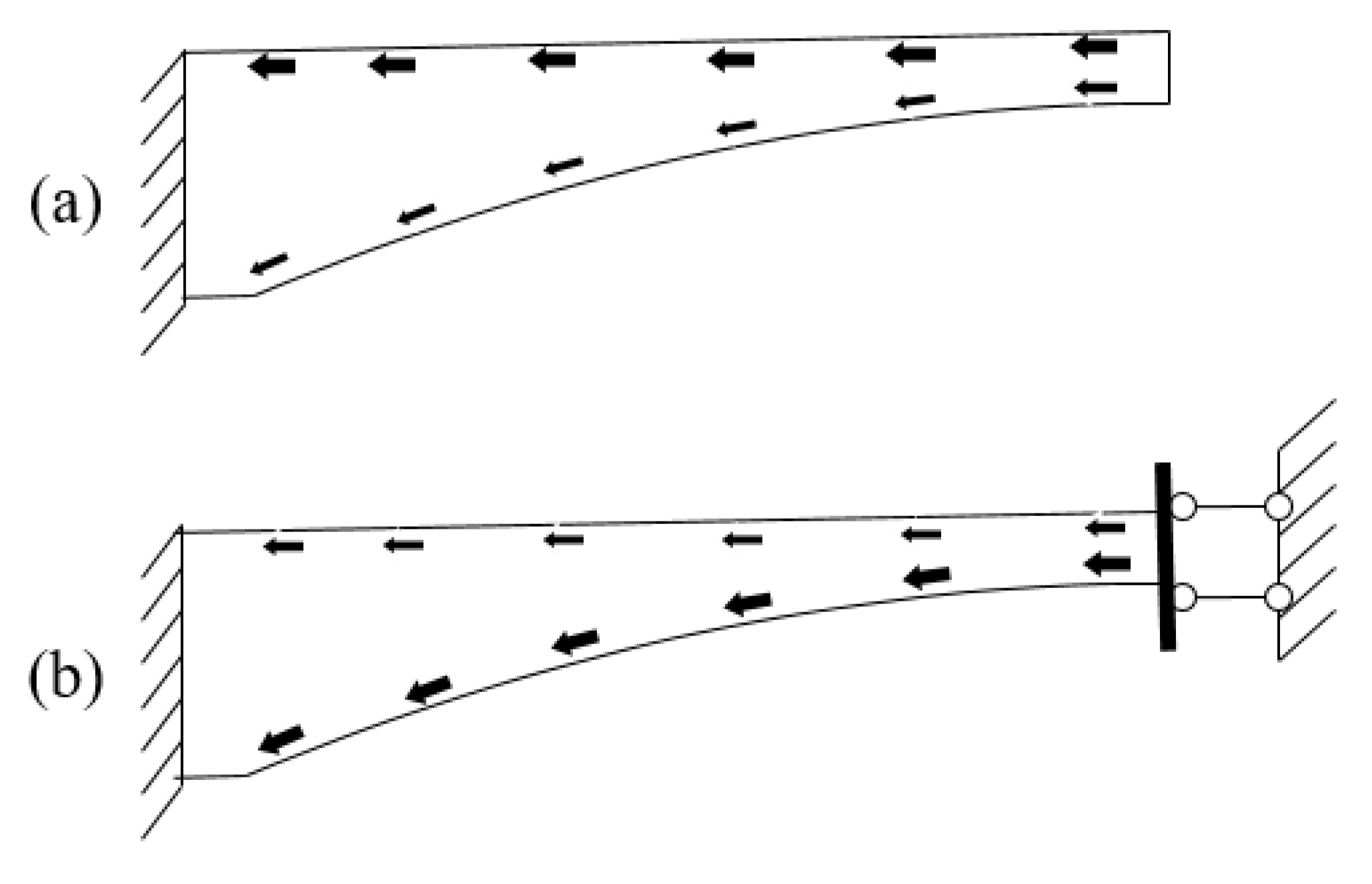
Never try to change the structure system when the cantilever bridge is reinforced. Material Inelasticity and Prestress Loss Coupling Effect will weak the bridge. It can also be understood by
Figure 16. In the cantilever bridge, the flow of the force is mainly through the top plate where the prestress tendon lies. After the transformation, the flow of the force finds a shot cut through the web and bottom plate, but the web is not designed to overcome such an amount of excessive flow. The web width of the KB Bridge is only 356mm along the whole middle span.
The side span of the beam can move freely when Material Inelasticity and Prestress Loss Coupling Effect occurs. And the redistribution moment caused by prestress tendon in
Figure 11(b) is relatively small. The excessive deflection hardly appears on the side span.
Since excessive deflection is an innate property in this study, excessive camber is suggested. the shortage(
) of the beam in
Figure 14 does not deteriorate the structure. But the excessive camber will change the geometry of the structure, for the rigid-frame bridge, the excessive camber that works like an arc bridge may cause inelastic strain on the piers which means the piers will bend under thrust. The method of excessive camber should be very careful, large amounts of excessive camber could jeopardize the piers.
The prestress tendon along the full length can be stretched over and over as external prestress, As the elastic modulus of the concrete does not decline, the external prestress will work in a certain amount.
7.2. Construction
Minimizing the inelastic property of concrete is the technical route of construction.
- (1)
Guarantee sufficient vibration of concrete [15]. The void in concrete during the pouring process should cause the inelasticity of the concrete.
- (2)
Curing age before applying prestress should meet the design requirement.
- (3)
Water cement ratio and the selection of cement varieties should incline to reduce the inelastic performance of concrete
8. Conclusions
The new theory explained the prestress loss and concrete inelastic model both. It worked well with the phenomenon: the steel bridge, the railway concrete bridge, and the Side span rarely have an excessive deflection. It gives the suggestion such as (1) Excessive camber with caution; (2) Stretching the bottom prestress in stages not at once; (3) Prestress tendon along the full length is useful; (4) Do not change the cantilever structure into the continuous structure during the reparation; (5) To increase the web thickness and stiffness of the middle span is an effective way to resist excessive deflection; (6) To reduce the inelastic performance of the concrete during construction.
References
- 楼庄鸿.国内外大跨径桥梁的现状和发展趋势(续三)[J].公路工程, 1993, 000(003):62-66.Doi:CNKI:SUN:ZNGL.0.1993-03-009.
- Bazant Z P, Hubler M H, Yu Q . Excessive Creep Deflections[J].Concrete International, 2011, 33(8):p.44-46.
- Yu Q, Bazant Z P, Wendner R . Improved Algorithm for Efficient and Realistic Creep Analysis of Large Creep-Sensitive Concrete Structures[J].ACI Structural Journal, 2012, 109(5):665-676. [CrossRef]
- Burgoyne C, Scantlebury R . Why did Palau Bridge collapse?[J]. Structural Engineer, 2006, 84(11):30-37.doi: Burgoyne, CJ and Scantlebury, R (2006) Why did Palau Bridge coll.
- Bazant Z P, Yu Q, Li G H . Excessive Long-Time Deflections of Prestressed Box Girders. I: Record-Span Bridge in Palau and Other Paradigms[J].Journal of Structural Engineering, 2012, 138(6):676-686. [CrossRef]
- Baant Z P, Yu Q, Li G H . Excessive long-time deflections of prestressed box girders[J].Journal of Structural Engineering, 2012(6):138. [CrossRef]
- Gilbert R I . Shrinkage, Cracking and Deflection- the Serviceability of Concrete Structures[J].Electronic Journal of Structural Engineering, 2001, 1. [CrossRef]
- Bob C.About the Causes of the Koror Bridge Collapse[J].Open Journal of Safety Science & Technology, 2014, 04(2):119-126. [CrossRef]
- Pan Z, Li B, Lu Z . Effective shear stiffness of diagonally cracked reinforced concrete beams[J]. Engineering Structures, 2014, 59(Feb.):95-103. [CrossRef]
- He Z Q , Tang M , Xu T ,et al.Additional Shear Stresses in Webs of Segmental Concrete Bridges due to Anchorage of Cantilever Tendons[J].Journal of Bridge Engineering, 2021(7):26. [CrossRef]
- Yongxue Jin, Chenglin Sun, Huifen Liu, Dong Xu, Analysis on the causes of cracking and excessive deflection of long-span box girder bridges based on space frame lattice models, Structures, Volume 50,2023, Pages 464-481, ISSN 2352-0124. [CrossRef]
- Tang M, C. Tang M C.The Story of the KB Bridge[M]. 2014.
- He Z Q, Li Y, Xu T, et al. Crack-based serviceability assessment of post-tensioned segmental concrete box-girder bridges[J].Structures, 2021. [CrossRef]
- 秦顺全.斜拉桥安装无应力状态控制法[J].桥梁建设, 2003(2):4. [CrossRef]
- Yang M, Gong J . Survey and investigation of performance of superstructure of long span bridges in China[C]//International Conference on Performance-based and Life-cycle Structural Engineering.2015. [CrossRef]
|
Disclaimer/Publisher’s Note: The statements, opinions and data contained in all publications are solely those of the individual author(s) and contributor(s) and not of MDPI and/or the editor(s). MDPI and/or the editor(s) disclaim responsibility for any injury to people or property resulting from any ideas, methods, instructions or products referred to in the content. |
© 2023 by the authors. Licensee MDPI, Basel, Switzerland. This article is an open access article distributed under the terms and conditions of the Creative Commons Attribution (CC BY) license (http://creativecommons.org/licenses/by/4.0/).
