Submitted:
02 August 2023
Posted:
03 August 2023
You are already at the latest version
Abstract
Keywords:
1. Introduction
- –
- A higher by 150%-250% throughput, as compared to conventional single- or even double-lane roundabouts. They are also superior to the signalised junctions by eliminating waiting time at traffic lights.
- –
- Traffic safety improvement by eliminating traffic conflicts, intersecting flows in particular. Worth noting is the reduction of fatalities or injuries by about 70% as compared to right-of-way intersections and by about 50% as compared to signalised intersections or conventional two-lane roundabouts. In addition, turbo roundabouts reduce the total number of road incidents by 85% and rear-end collisions by 95%.
- –
- Land take comparable to double-lane approach and exit signalised intersections accommodating simultaneous movement of two tractor-trailer units in any directions during one signal cycle.
- –
- Lower future maintenance costs and lower environmental and social cost of the project compared to signalised intersections, with only slightly higher project cost.
- –
- Vehicles that are about to enter the roundabout through any leg are not obliged to not give way to the vehicles navigating through the roundabout on any of the two traffic lanes of the roundabout carriageway
- –
- Having to give way to vehicles riding on all the three traffic lanes of the roundabout carriageway is complicated and impracticable for many road users. For this reason, larger turbo roundabouts should be provided with traffic lights as an additional traffic control measure.
- –
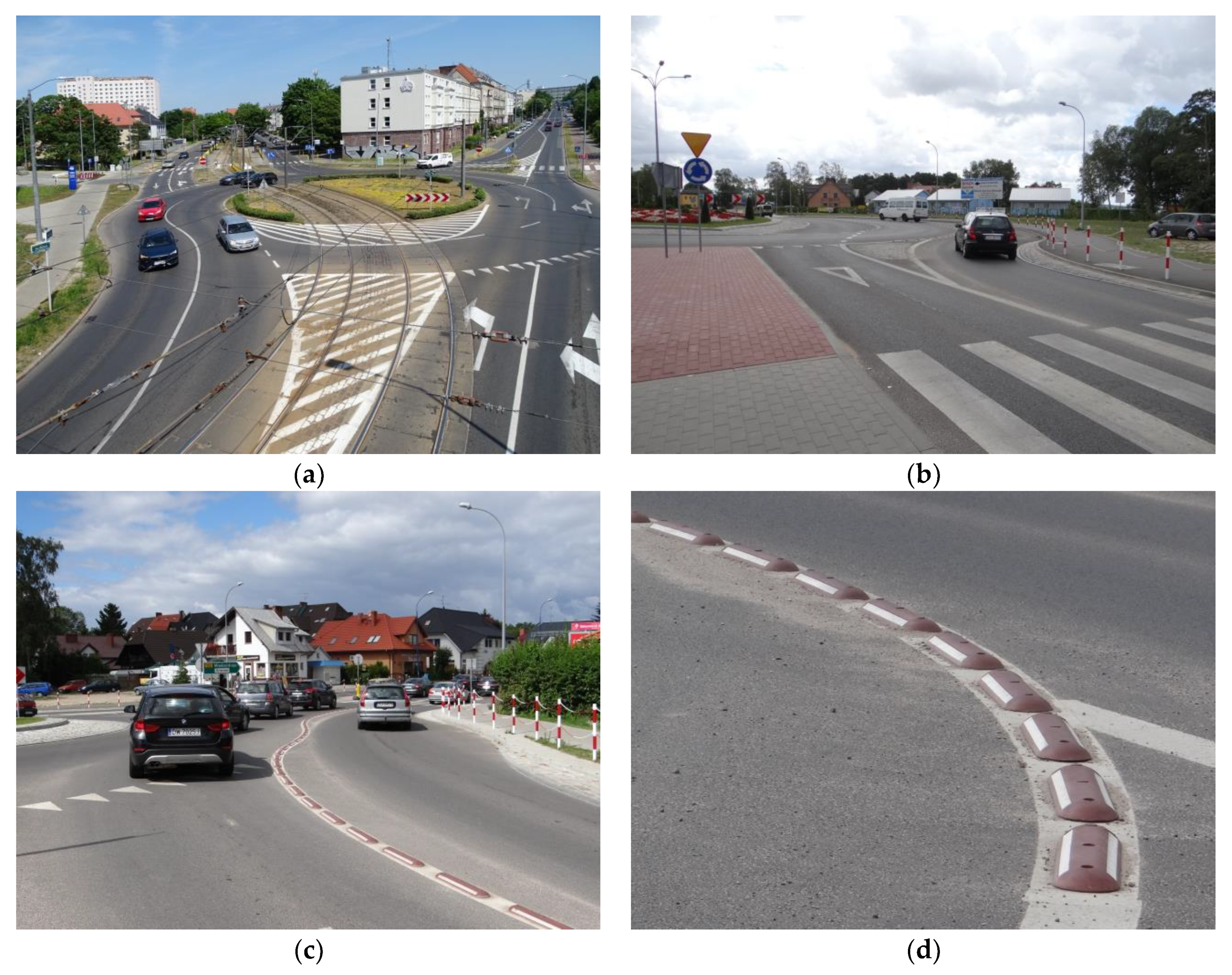
- A raised curb installed in the separation lane allocates a specific lane for each vehicle, which it shall not change while navigating through the roundabout. There are no traffic conflicts due to weaving or crossing. Turbine roundabouts do not allow driving in circles from any direction
- –
- Vehicles are gradually shifted from the inside to the outside, following spiral paths without any crossing movements. The smooth path of travel between the raised kerb separation lanes allows driving through the roundabout at a maximum speed of 35 to 40 km/h.
- –
- Dual lane exits should be provided on the main legs to maximise the roundabout throughput. However, with limited straight-through traffic a single exit lane may suffice.
- –
- At each leg, a road user riding on the outer lane must have an option to exit or continue navigating through the turbo roundabout. A road user driving on the inner lane will have this choice on the next segment.
2. Materials and Methods
2.1. Study Area
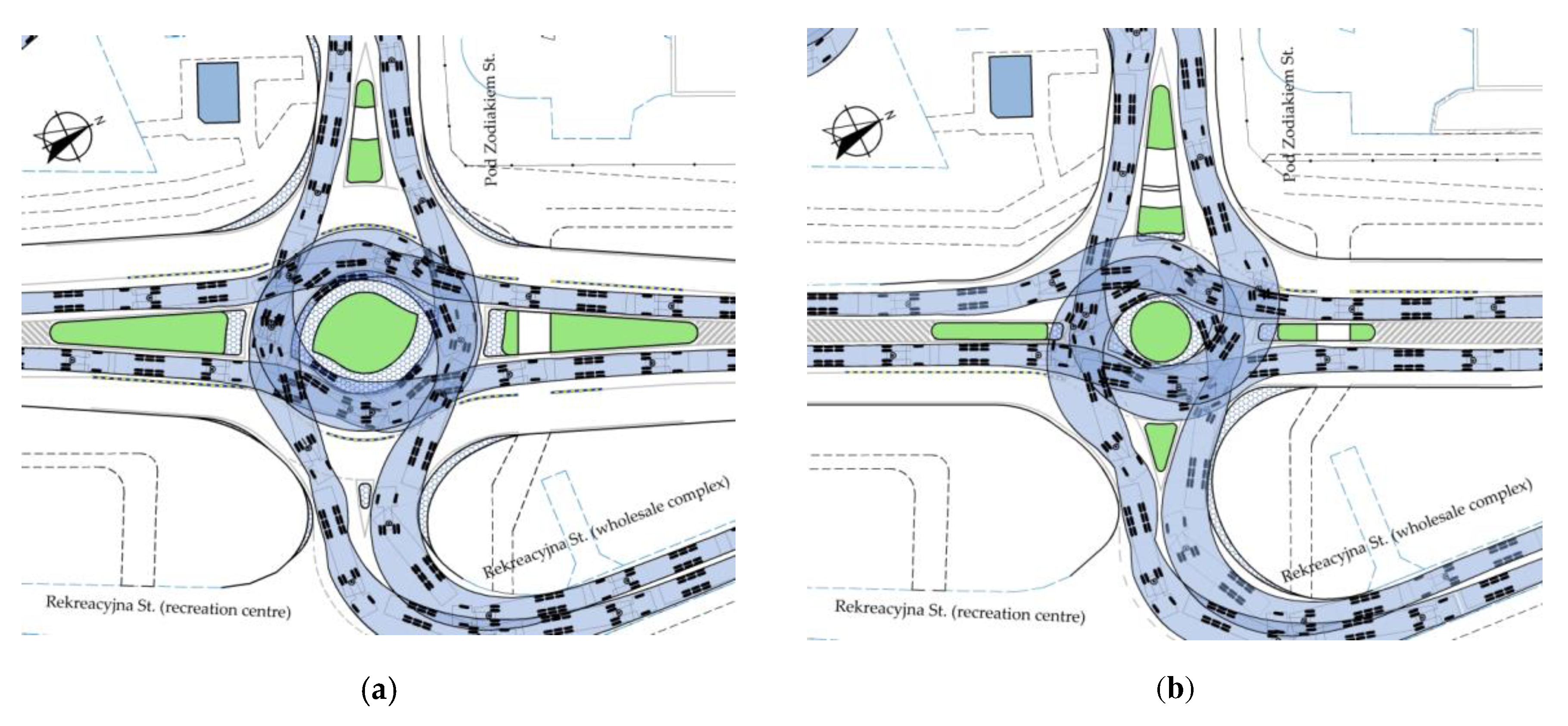
2.2. Design Vehicles and Swept Path
2.3. Standard turbo roundabout in a constrained site
- –
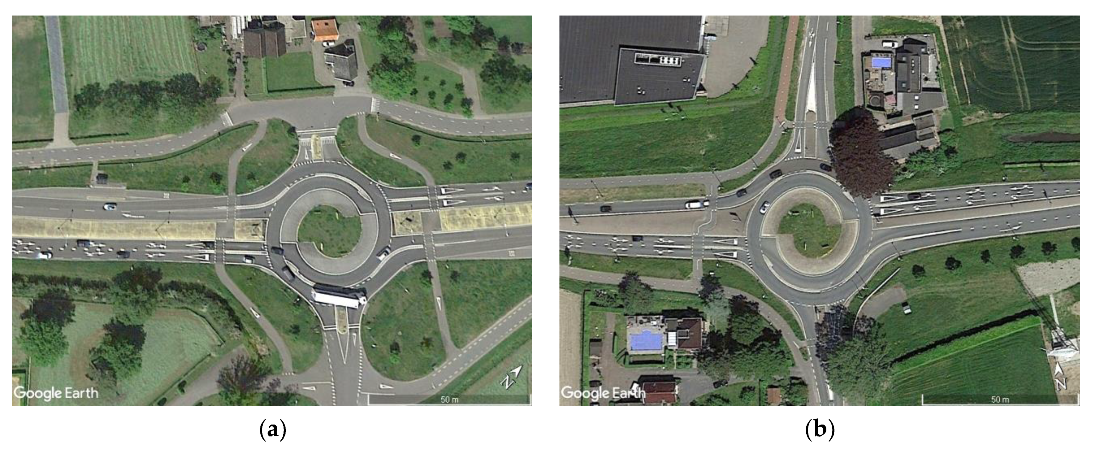
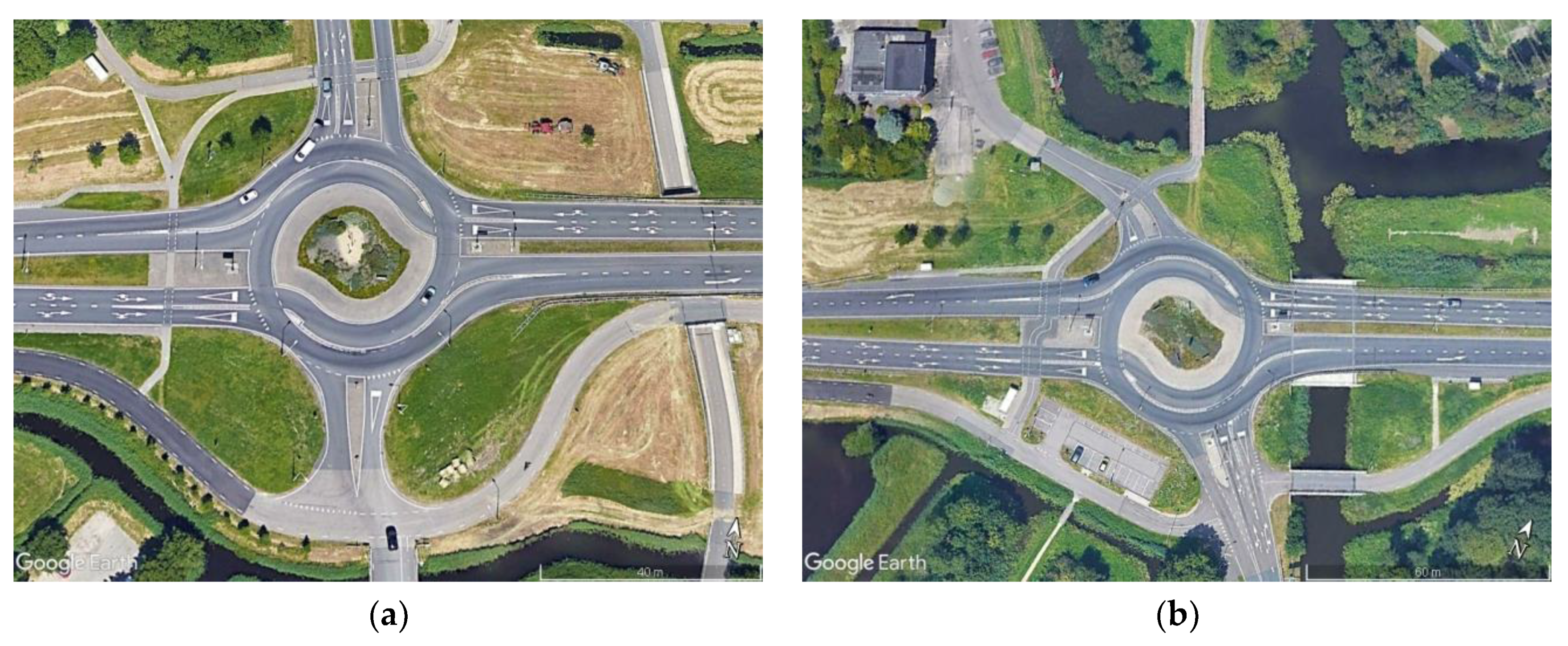
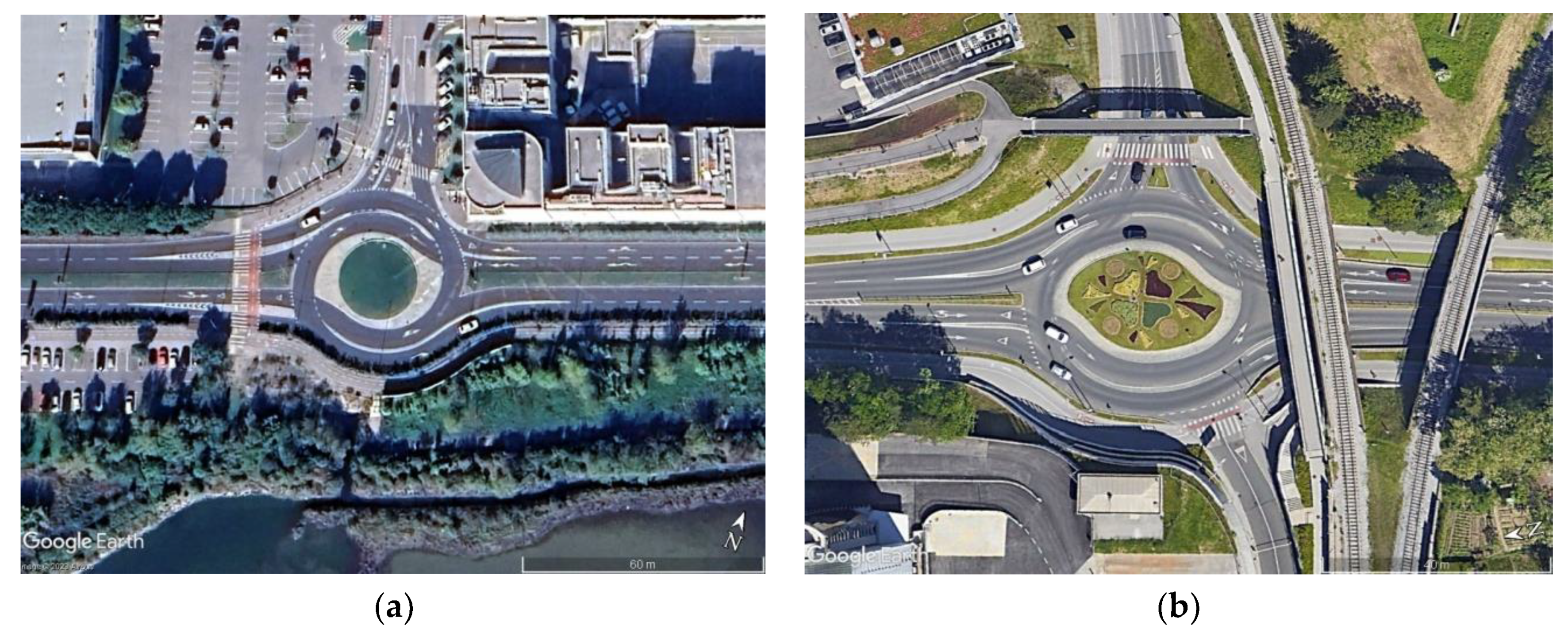
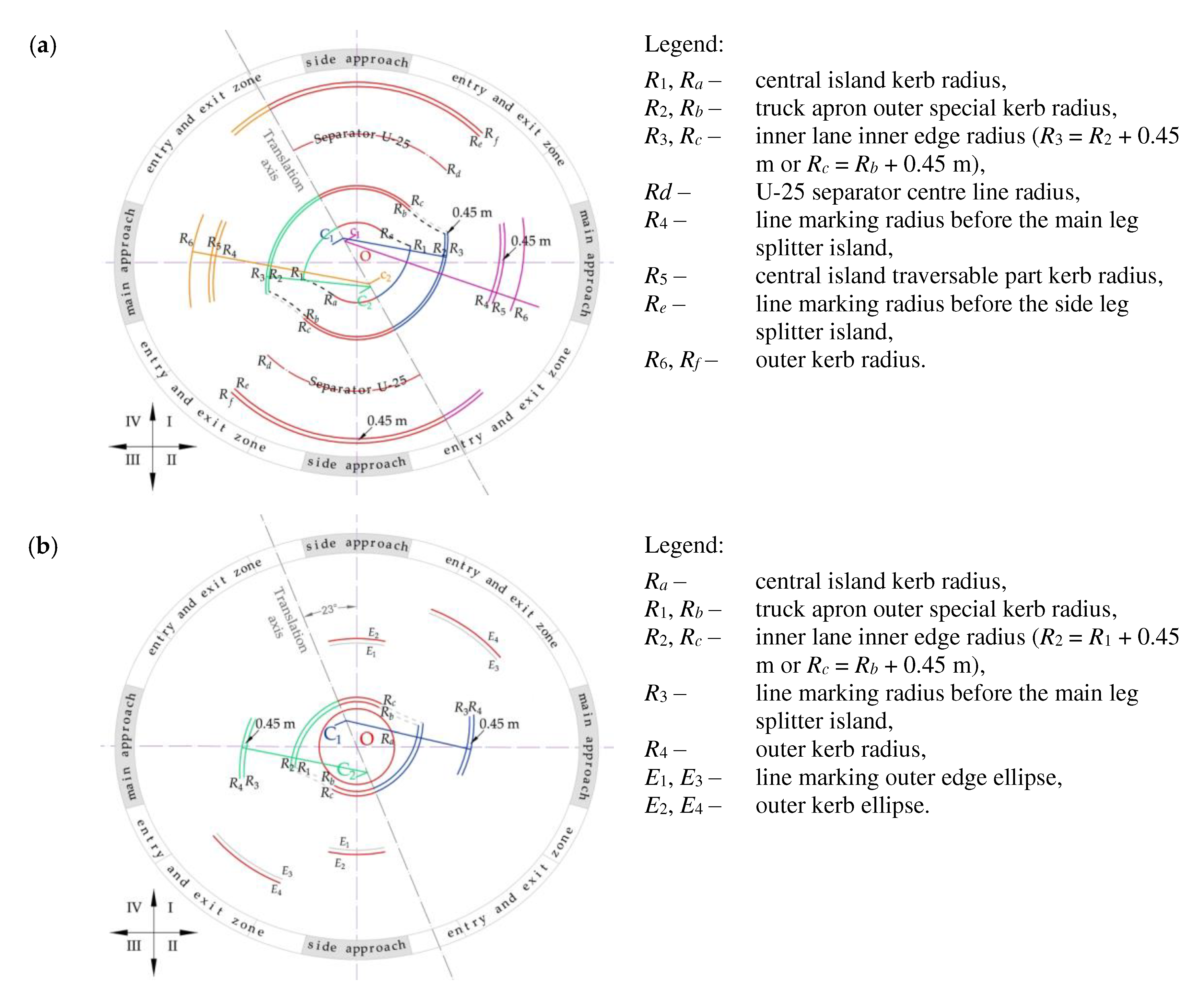
- "flattened" Egg turbo roundabouts,
- –
- elliptical turbo roundabouts with a central island shaped typically for a turbo roundabout,
- –
- elliptical turbo roundabouts with elliptical central island.
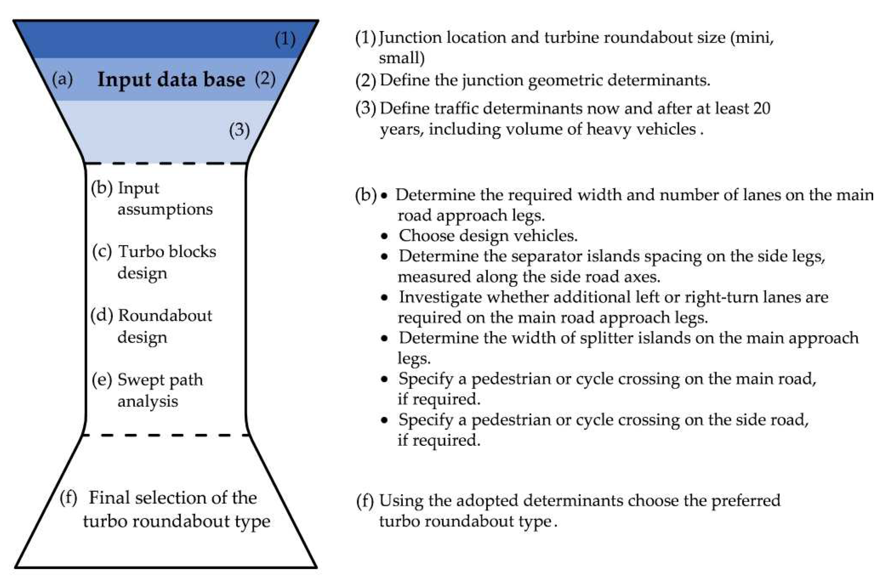
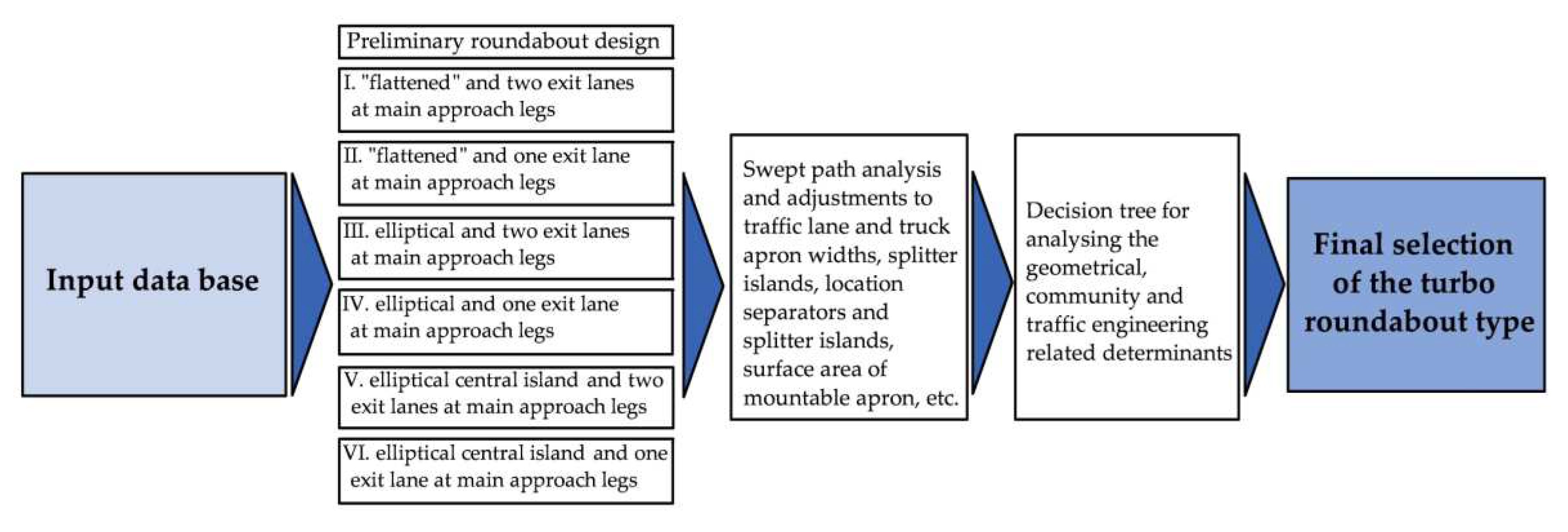
2.4. Turbo roundabout selection method for constrained areas
- –
- constraints located sideways of the main road, having a determining effect on limitation of the number of exit lanes on the main road approach legs to one,
- –
- distance of the existing side road constraints, measured along the side road from the main road centreline, having a determining effect on the practicable design vehicle turn movements and splitter island design (i.e. length and type: conventional or traversable),
- –
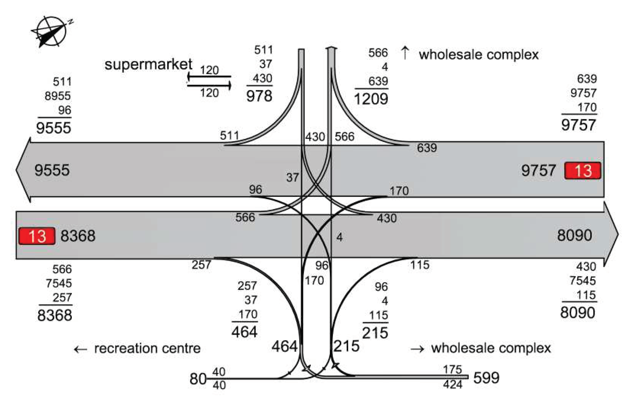
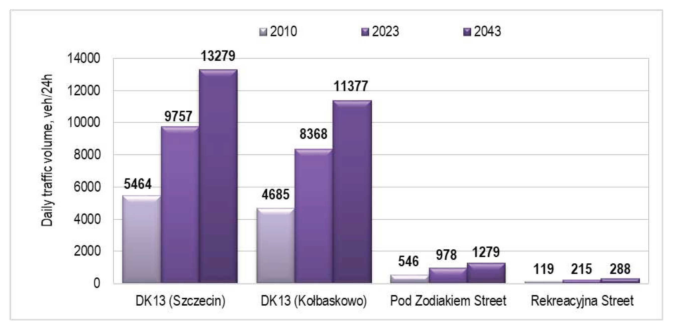
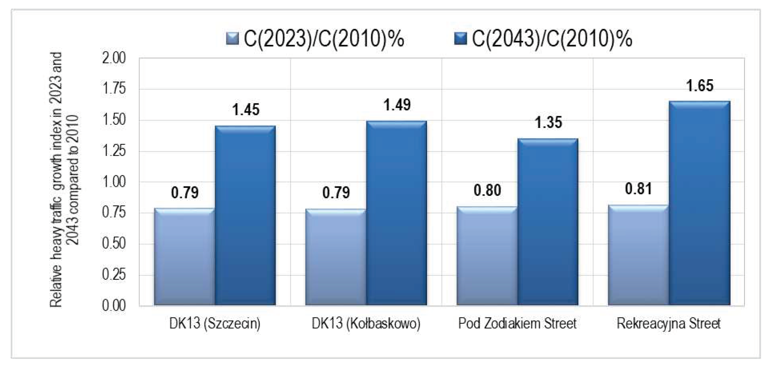
- total current and projected traffic volumes, traffic flow allocation on both roads and traffic composition indicating the expected heavy traffic volume on the turn movements of the analysed legs,
- –
- type of developments around the planned roundabout location.
3. Results
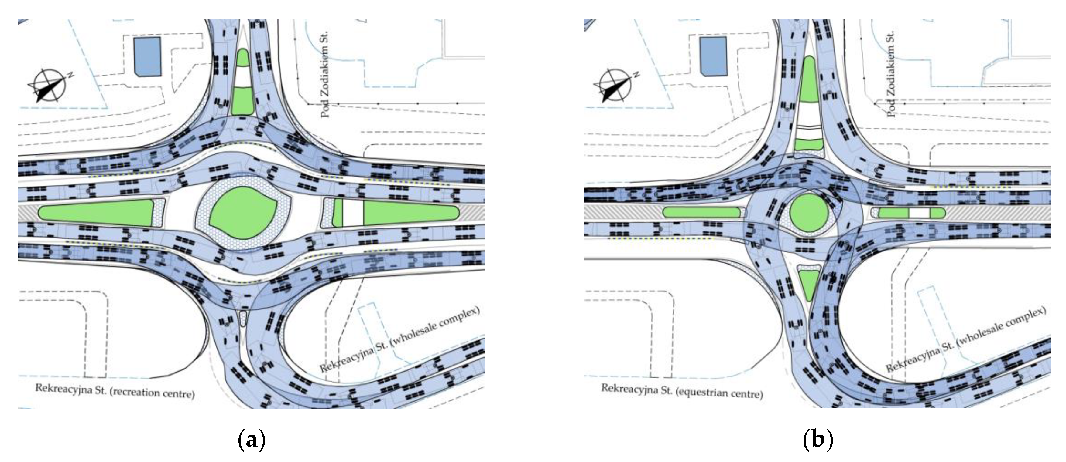
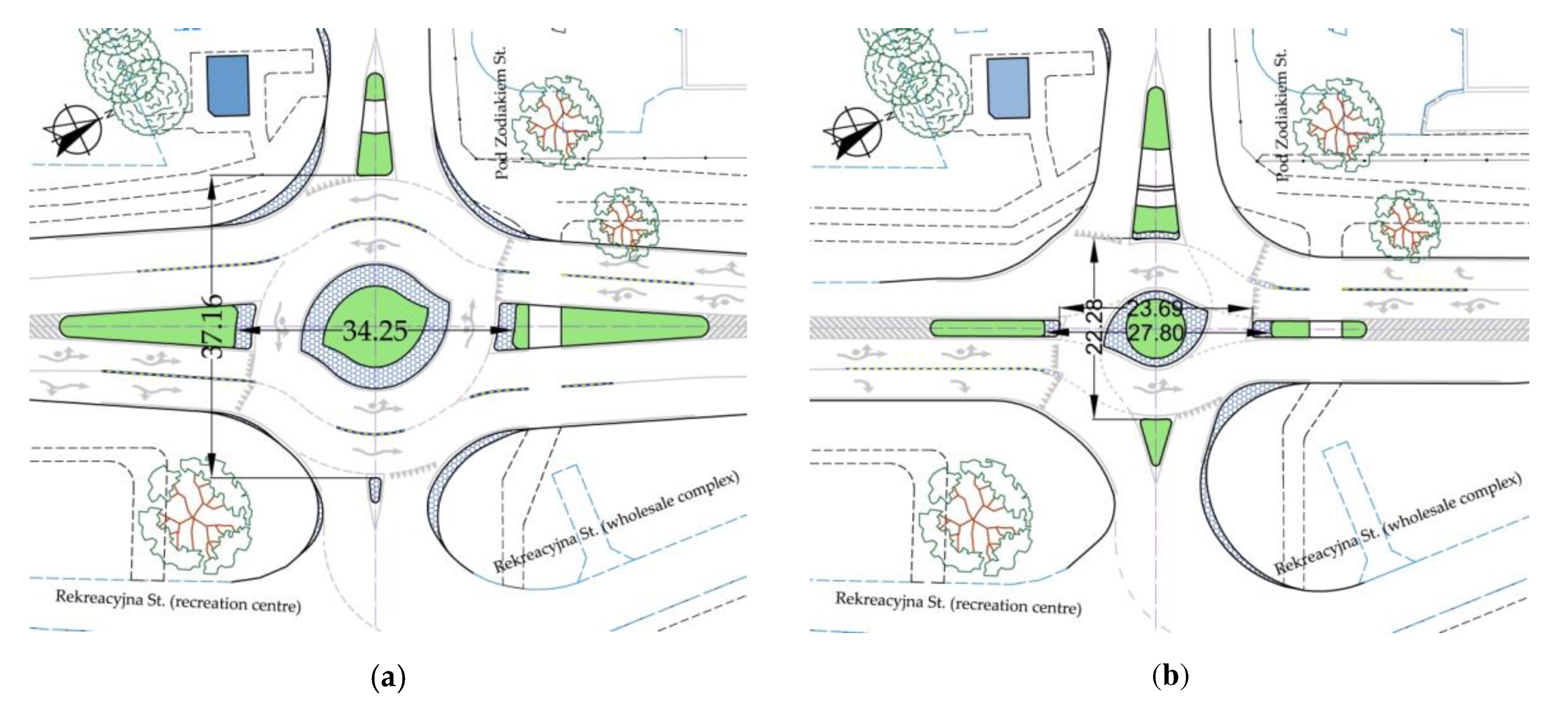
3.1. "Flattened" turbo roundabout featuring a 0.24 m wide separation lane
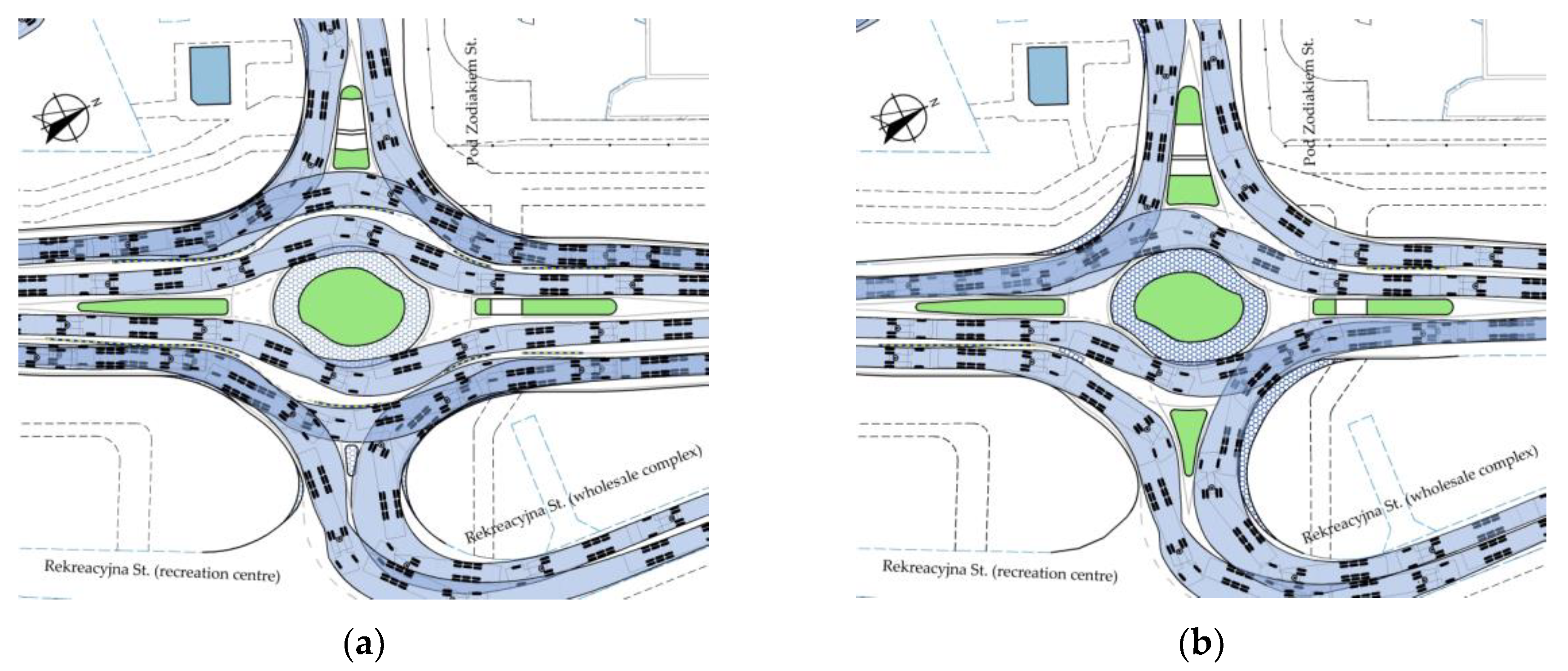
3.2. Elliptical turbo roundabout featuring a 0.24 m wide separation lane and a standard shape central island
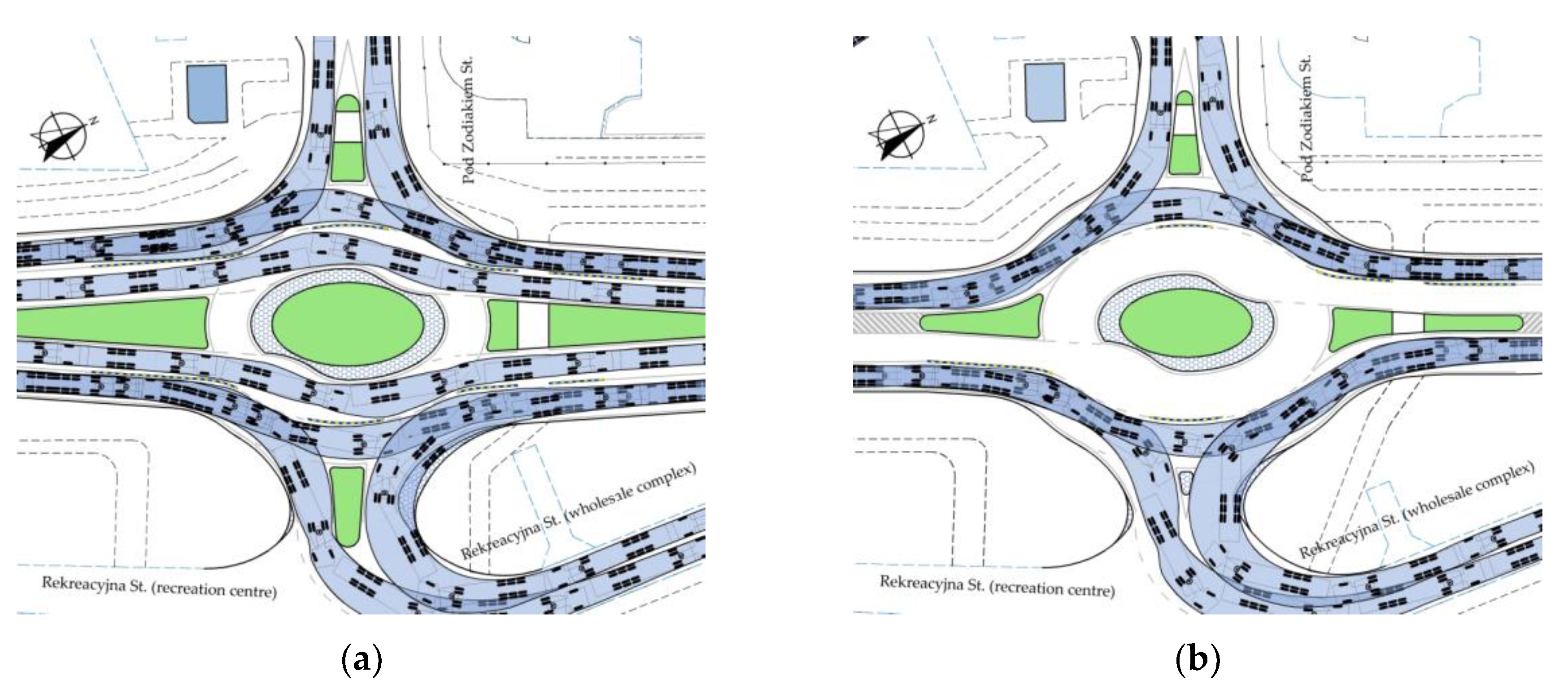
3.3. Elliptical turbo roundabout featuring a 0.24 m wide separation lane and an elliptical central island
4. Discussion
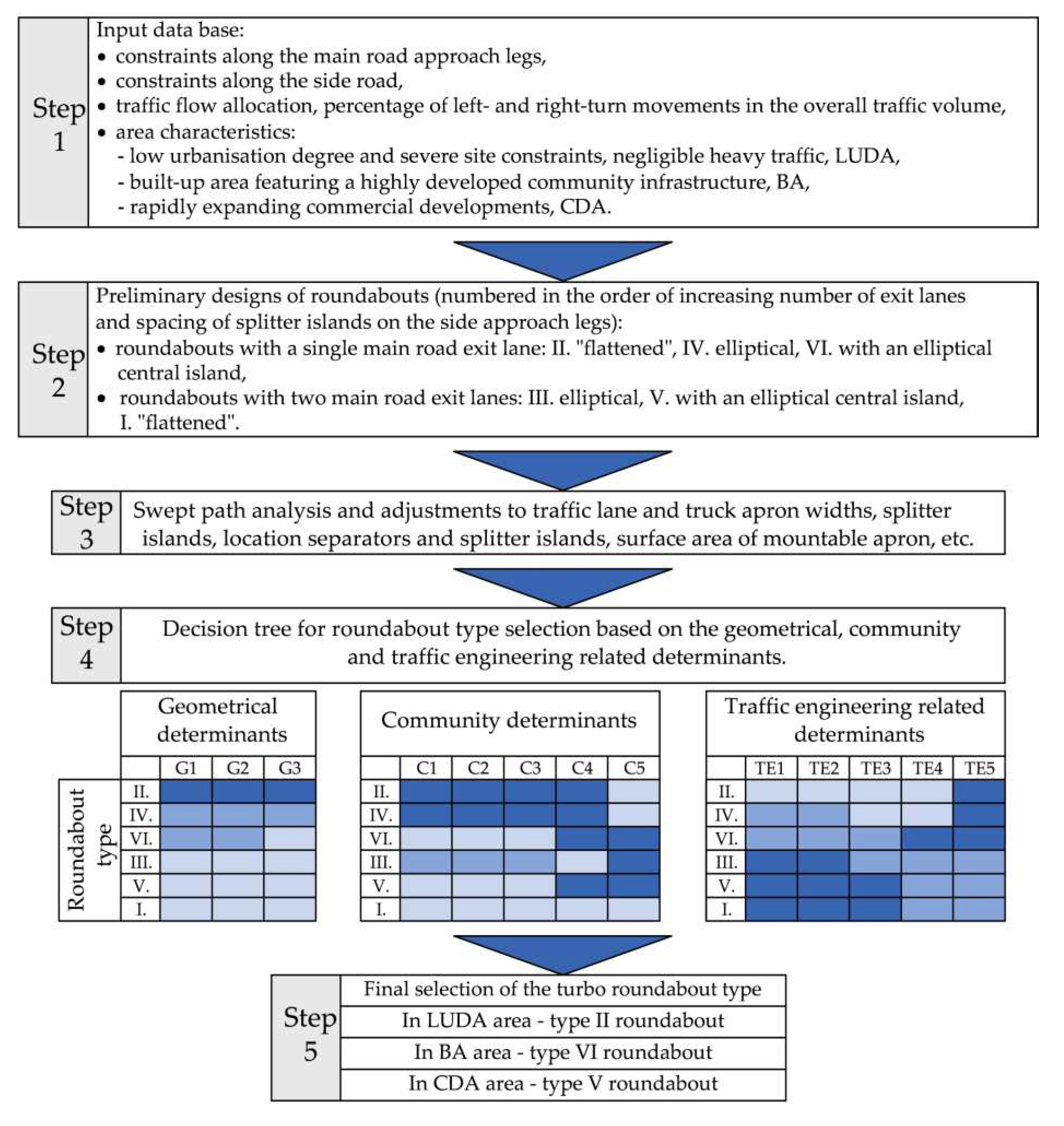
- (a)
- LUDA low urbanisation degree areas – single family housing estates or woonerf, the side road handles the local traffic composed mainly of the residents’ passenger cars and municipal service vehicles if appropriate,
- (b)
- BA built-up area with a developed community infrastructure, requiring provision of pedestrian and cycle crossings running through splitter islands on the side approach legs,
- (c)
- CDA highly commercially developed area along the side road, including primarily very big warehouses and wholesale markets resulting in high volumes of articulated trucks on turn movements.
- –
- dark blue means good score i.e. lower cost, bigger pedestrian and cycling amenities, better handing of traffic in the roundabout area by adequate traffic flow allocation: two traffic lanes for the straight movements for high traffic volumes on the main road or a dedicated turn lane for a high heavy traffic volume on this movement, etc.
- –
- light blue means the opposite score, i.e. less pedestrian and cyclist amenities, no dedicated right- or left-turn lanes despite a high heavy-traffic volume, etc.
- –
- blue designates an intermediate score.
- –
- number of straight-through lanes on the roundabout carriageway G1,
- –
- number of traffic lanes on the main approach legs G2,
- –
- spacing of splitter islands dividing measured along the side road G3.
- –
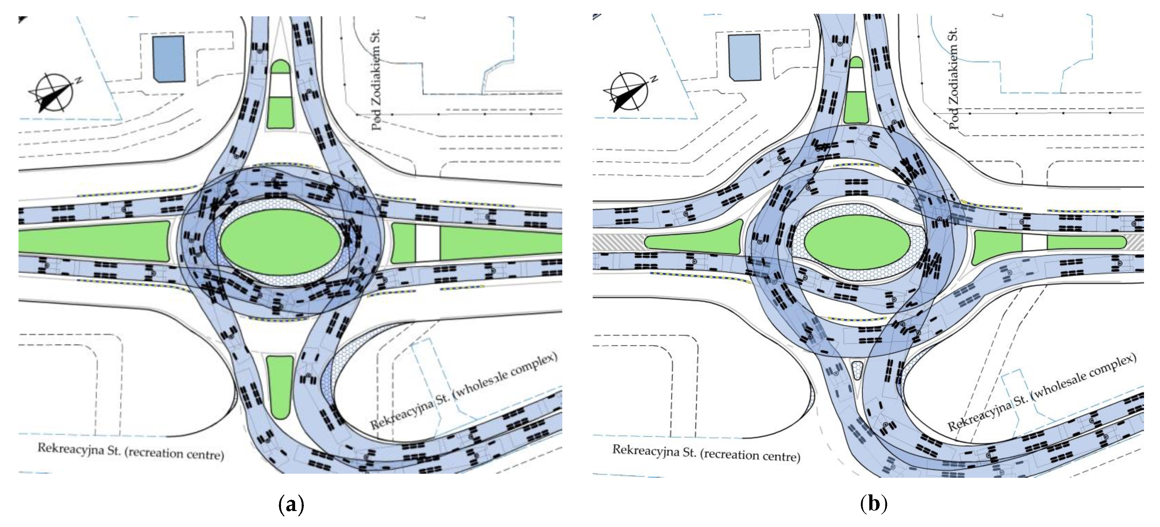
- spacing of splitter islands on the main road approach legs, which, upon exceeding a certain limit, may require reconstruction of the bus stops, as may be located, for example near the analysed intersection, or longer pedestrian travel distances to these bus stops C1, this increasing the cost as a result (Figure 11a and Figure 17),
- –
- the spacing of splitter islands on the main road approach legs increasing the pedestrian travel distances to the pedestrian crossings and the nearby parking areas S2, at the inlets of the main road, resulting in longer pedestrian crossings and longer accesses to nearby C2 car parks, this increasing the cost as a result (Figure 11a and Figure 17),
- –
- spacing of splitter islands on the side legs, which, upon exceeding a certain limit in a constrained site may preclude provision of a cycle crossing through the side road C3, and thus the roundabout type may get the lowest score and may be discouraged for highly urbanised areas featuring a highly developed cycling infrastructure (Figure 11a and Figure 17),
- –
- requirement of mountable apron areas over pedestrian crossing width C4, causing disturbance to pedestrian traffic, especially for people on wheelchairs, and thus this roundabout type may get the lowest score and may be discouraged for highly urbanised areas featuring a highly developed community infrastructure,
- –
- requirement for traversable parts in the beginning of splitter islands C5, increasing the travel distance to pedestrian crossing and possibly affecting the traffic safety, thus resulting in a lower score given for this roundabout.
- –
- the required number of straight-through traffic lanes on the roundabout carriageway, having a considerable effect on the roundabout throughput when dealing with high traffic volumes carried by the main road TE1,
- –
- the number of the main road exit lanes, having a considerable effect on the roundabout throughput when dealing with high traffic volumes carried by the main road TE2,
- –
- distance to adjacent junctions on the main road requiring provision of additional traffic lanes before them, which, in case of close proximity of such junctions, has a considerable bearing on the carriageway division into traffic lanes on the approach to the analysed roundabout and installation of appropriate road surface markings TE3,
- –
- high left-turning traffic volume requiring, for example, provision of a dedicated traffic lane on the roundabout carriageway TE4,
- –
- high right-turning traffic volume requiring, for example, provision of a dedicated traffic lane on the roundabout carriageway TE5.
5. Conclusions
- –
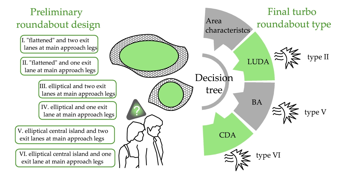
- The currently available turbo roundabout design guidelines do not include turbo blocks that could be used for designing such roundabouts where site constraints are an issue.
- –
- The proposed turbo blocks for designing six types of turbo roundabouts of different shapes and roundabout carriageway division offer new turbo roundabout design options for constrained sites.
- –
- Based on pre-determined criteria and determinants three turbo roundabout types were recommended for constrained site projects, the final choice depending on the adjacent land characteristics:
- In low urbanisation degree areas LUDA (single family neighbourhoods or woonerf) with negligible heavy traffic volume and most severe site constraints a "flattened" turbo roundabout featuring one lane on the main road approach leg should be the option of choice.
- In built-up areas featuring well-developed community infrastructure BA, requiring pedestrian and cycle crossings to run through splitter islands on the side legs, with less severe site constraints and a considerable share of heavy traffic on the left- and right-turn movements the option of choice is an elliptical turbo roundabout with an elliptical central island and one exit lane on the main road approach leg.
- In areas with rapidly growing commercial developments CDA along a side road an elliptical roundabout featuring an elliptical central island and two lanes on the main road approach leg should be considered.
- –
- As the authors plan to continue the research with throughput analyses for different traffic flow allocations, new findings and roundabout selection guidelines taking into account may be expected to come.
Author Contributions
Institutional Review Board Statement
Informed Consent Statement
Conflicts of Interest
Appendix A
Appendix B
Appendix C
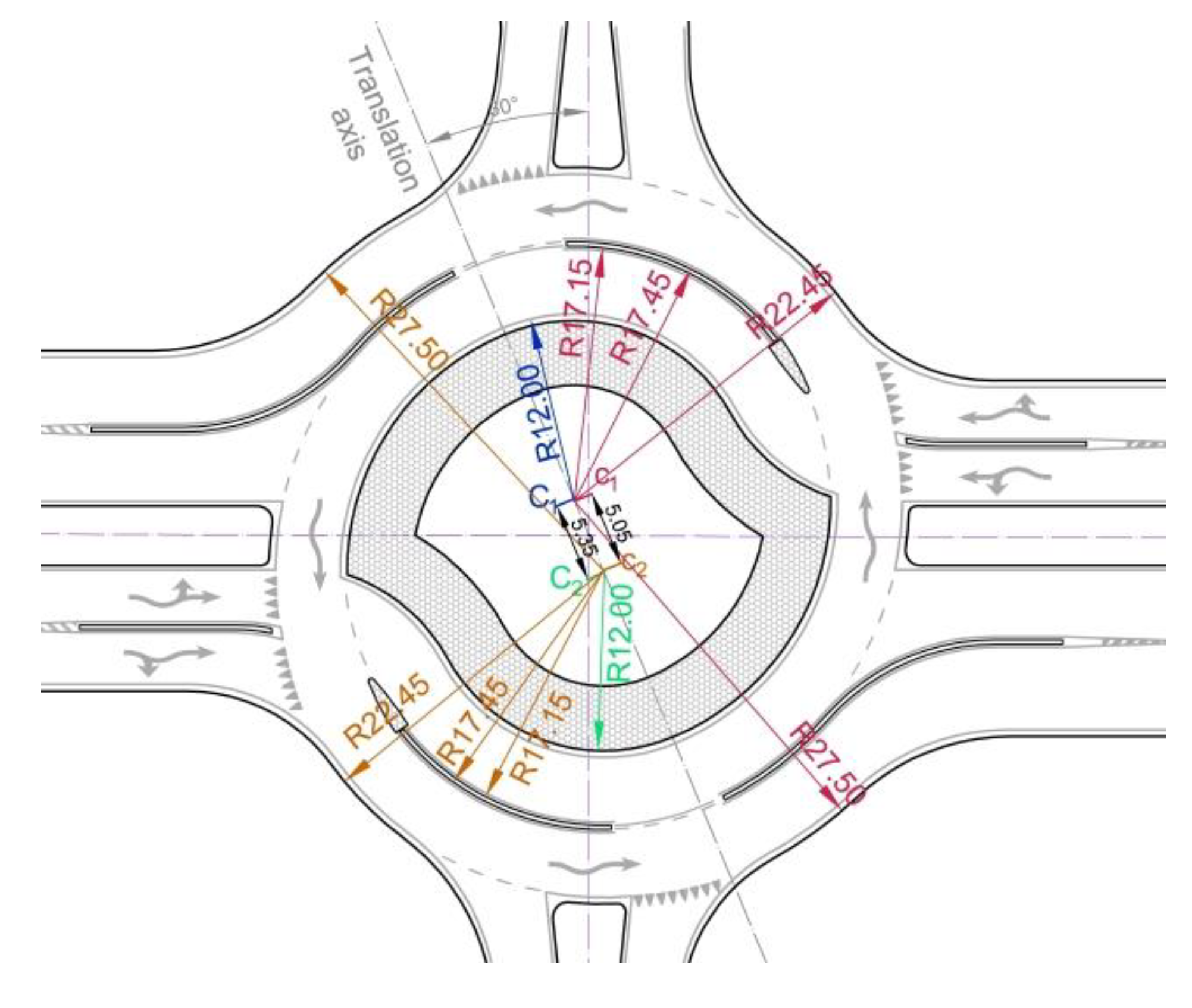
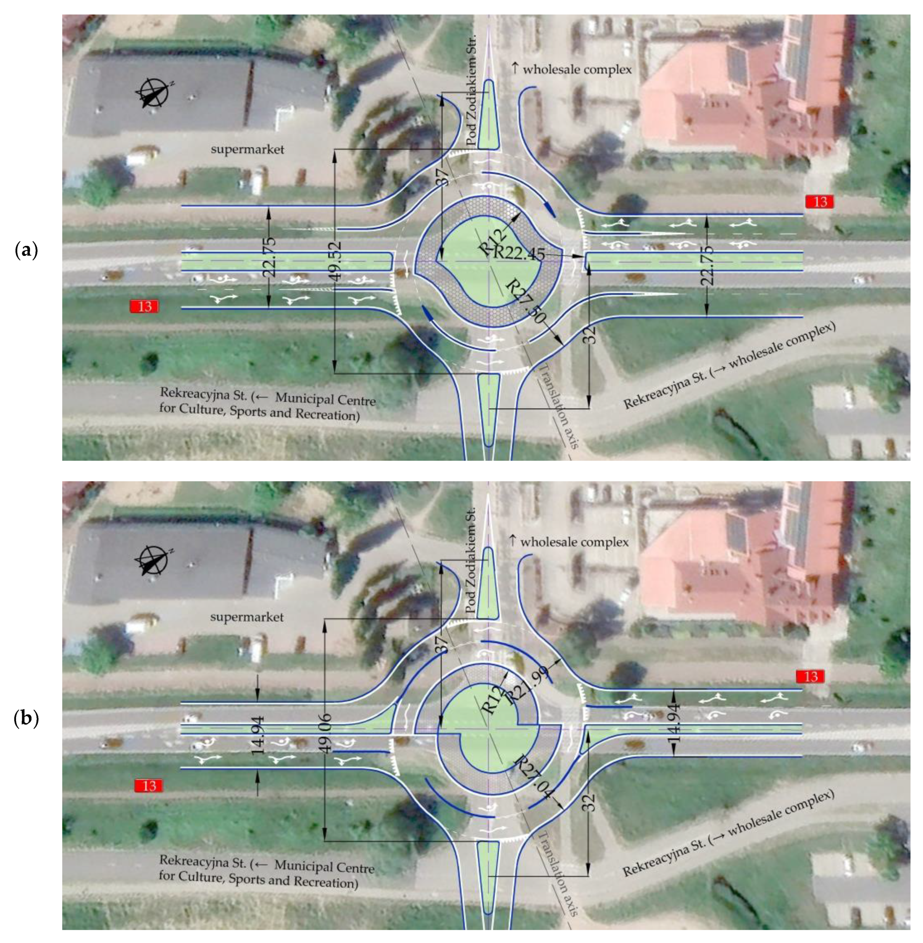
| Main elements of a transverse cross-section of the roundabout | Mathematical designation | Radius and measurement in m | |||
|---|---|---|---|---|---|
| Fastest path speed for a passenger car in km/h | v | 37–41 | 37– 39 | ||
| Mini roundabout | Small roundabout | ||||
| Figure 7a and Figure A4 | Figure 7b | ||||
| Lane divider between driving lanes | 0.70 | 0.24 | 0.70 | 0.24 | |
| Radii | |||||
| Inner radius of the inner lane | R1 | 10.50 | 10.50 | 12.00 | 12.00 |
| Outside radius of the inner lane | R2 | 15.85 | 15.65 | 17.15 | 16.95 |
| Inner radius of the outside lane | R3 | 16.15 | 15.89 | 17.45 | 17.19 |
| Outside radius of the outside lane | R4 | 21.15 | 20.69 | 22.45 | 21.99 |
| Curve lane divider entry | Rt | 12 | 12 | 12 | 12 |
| Curve lane divider exit | Ra | 14 | 14 | 14 | 14 |
| Widths | |||||
| Overrun area (truck apron) width | 5.00 | 5.00 | 5.00 | 5.00 | |
| Width, inside lane | bu | 4.70 | 4.70 | 4.50 | 4.50 |
| Width, outside lane | bv | 4.35 | 4.35 | 4.35 | 4.35 |
| Shift of inner arc centers along the translation axis(stakeout: R2, R3, R4) | ∆v | 5.75 | 5.75 | 5.35 | 5.35 |
| Shift of outer arc centers along the translation axis(stakeout: R0, R1) | ∆u | 5.05 | 5.05 | 5.05 | 5.05 |
Appendix D
References
- Overkamp, D.P.; van der Wijk, W. Roundabouts – Application and design, A practical manual; Royal Haskoning DHV. Dutch Ministry of Transport, Public Works and Water Management, Partners for Roads: Hague, Netherlands, 2009. [Google Scholar]
- Fortuijn, L.G.H. Turborotonde en turboplein: ontwerp, capaciteit en veiligheid; Trail Thesis series T 2013/1, Trail Research School, Dissertation of Delft University of Technology: Delf, Netherlands, 2013. [Google Scholar]
- CROW. Turborotondes; CROW Publication No. 257: Hague, Netherlands, 2008. [Google Scholar]
- Fortuijn, L.; Salomons, A.M. Capacity Increase through connectivity for the i-Roundabout and i-Turbo roundabout. IEEE Xplore 2020. [Google Scholar] [CrossRef]
- Gallelli, V.; Vaiana, R. Safety improvements by converting a standard roundabout with unbalanced flow distribution into an egg turbo roundabout: Simulation approach to a case study. Sustainability 2019, 11, 466. [Google Scholar] [CrossRef]
- Liu, Q.; Deng, J.; Shen, Y.; Wang, W.; Zhang, Z.; Lu, L. Safety and Efficiency Analysis of Turbo Roundabout with Simulations Based on the Lujiazui Roundabout in Shanghai. Sustainability 2020, 12, 7479. [Google Scholar] [CrossRef]
- Ciampa, D.; Diomedi, M.; Giglio, F.; Olita, S.; Petruccelli, U.; Restaino, C. Effectiveness of unconventional roundabouts in the design of suburban intersections. European Transport\Trasporti Europei 2020. [Google Scholar] [CrossRef]
- Silva, A.B.; Mariano, P.; Silva, J.P. Performance assessment of turbo-roundabouts in corridors. Transportation Research Procedia 2015, 10, 124–133. [Google Scholar] [CrossRef]
- CROW. Eenheid in rotondes; CROW Publication: Ede No. 126: Hague, Netherlands, 1998. [Google Scholar]
- Dirk de Baan. Aantal 'gespotte' turborotondes. Available online: https://www.dirkdebaan.nl/types.html (accessed on 2 July 2023).
- Google Earth. Available online: http://www.earth.google.com (accessed on 2 July 2023).
- Tollazzi, T. Turbo" krožišča: krožna križišča s spiralnim potekom krožnega vozišča; Ministrstvo za promet, Direkcija Republike Slovenije za ceste: Slovenia, Ljubljana, 2008. [Google Scholar]
- Tollazzi, T.; Mauro, R.; Guerrieri, M.; Rencelj, M. Comparative analysis of four new alternative types of roundabouts: "turbo", "flower", "target" and "four-flyover" roundabout. Periodica Polytechnica Civil Engineering 2015, 60, 51–60. [Google Scholar] [CrossRef]
- Tollazzi, T. Alternative types of roundabouts. An informational guide. Springer Tracts on Transportation and Traffic 2015, 6. [Google Scholar] [CrossRef]
- Tollazzi, T. Experiences with Alternative Types of Roundabouts in Slovenia, Conference European Road Assessment (EuroRAP) 3-5 January 2020 Brussels, Belgium. Available online: https://eurorap.org/wp-content/uploads/2020/01/3-5-Tollazzi-Konferenca-o-prometni-varnosti-2016.pdf (accessed on 2 July 2023).
- Grabowski, R. Turbo-roundabouts as an alternative to standard roundabouts with the circular centre island. Roads and Bridges – Drogi i Mosty 2012, 11, 215–231. [Google Scholar]
- Leonardi, S.; Distefano, N. Turbo-Roundabouts as an Instrument for Improving the Efficiency and Safety in Urban Area: An Italian Case Study. Sustainability 2023, 15, 3223. [Google Scholar] [CrossRef]
- Guerrieri, M.; Tollazzi, T. Analysis of Kinematic Parameters and Driver Behavior at Turbo Roundabouts. J. Transp. Eng., Part A: Systems 2018, 144, 04018020. [Google Scholar] [CrossRef]
- Vasconcelos, L.; Silva, A.B.; Seco, A.M.; Fernandes, P.; Coelho, M.C. Turboroundabouts: Multicriterion Assessment of Intersection Capacity, Safety, and Emissions. Journal of Transportation Research Record 2014, 2402, 28–37. [Google Scholar] [CrossRef]
- Vasconcelos, L.; Silva, A.B.; Seco, A.M. Capacity of normal and turbo-roundabouts: comparative analysis. Proceedings of the Institution of Civil Engineers – Transport 2014, 167, 88–99. [Google Scholar] [CrossRef]
- Pitlova, E.; Kocianova, A. Case Study: Capacity Characteristics Comparison of Single-lane Roundabout and Turbo-roundabouts. Procedia Engineering 2017, 192, 701–706. [Google Scholar] [CrossRef]
- Šarić, A.; Lovrić, I. Multi-lane Roundabout Capacity Evaluation, Front. Built Environ. Frontiers in Built Environment. Sec. Transportation and Transit Systems 2017, 3, 42. [Google Scholar] [CrossRef]
- Kocianova, A. Capacity Limits of Basic Turbo-Roundabouts. Communications – Scientific Letters of the University of Zilina 2016, 18, 90–98. [Google Scholar] [CrossRef]
- Gallelli, V.; Vaiana, R. Safety improvements by converting a standard roundabout with unbalanced flow distribution into an egg turbo roundabout: simulation approach to a case study. Sustainability 2019, 11, 466. [Google Scholar] [CrossRef]
- Urząd Miasta. Przestrzenny plan zagospodarowania przestrzennego miasta. Urząd Miasta w Szczecinie, 2022. Available online: https://bip.um.szczecin.pl/chapter_11424.asp (accessed on 19 May 2022).
- GDDKiA. Generalny Pomiar Ruchu GPR 2020/2021. Available online: https://www.gov.pl/web/gddkia/generalny-pomiar-ruchu-20202021 (accessed on 25 May 2023).
- Rozporządzenie Ministra Infrastruktury z dnia 24 czerwca 2022 r. w sprawie przepisów techniczno-budowlanych dotyczących dróg publicznych, Dziennik Ustaw, Warszawa, z dnia 20 lipca 2022 r., poz. 1518.
- Bąk, R.; Gaca, S.; Ostrowski, K.; Tracz, M.; Woźniak, K. Wytyczne projektowania skrzyżowań drogowych WR-D-31-3. Ronda, Ministerstwo Infrastruktury, Warszawa 2022.
- Corriere, F.; Guerrieri, M. Performance analysis of basic turbo-roundabouts in urban context. Procedia – Social and Behavioral Sciences 2012, 53, 622–632. [Google Scholar] [CrossRef]
- Chan, S. Radial, left or right offset alignment and roundabout vehicle speeds. Roundabouts Now 2017, 3, 24–27. [Google Scholar]
- Chan, S.; Livingston, R. (2015) Design vehicle’s influence to the geometric design of turbo roundabouts. Teach America. 2017. Available online: http://teachamerica.com/RAB14ppr147_Chan.pdf (accessed on 25 April 2021).
- Campbell, D.; Jurisich, I.; Dunn, R. Improved multi-lane roundabout designs for urban areas; Research Report 476, NZ Transport Agency: Wellington, New Zealand, 2012. [Google Scholar]
- Džambas, T.; Ahac, S.; Dragčević, V. Design of turbo roundabouts based on the rules of vehicle movement geometry. Journal of Transportation Engineering 2016, 142. [Google Scholar] [CrossRef]
- Džambas, T.; Dragčević, V.; Korlaet, Ž. Optimizing geometric design of standard turboroundabouts. KSCE Journal of Civil Engineering 2020, 24, 3034–3049. [Google Scholar] [CrossRef]
- Severino, A.; Pappalardo, G.; Trubia, S. Safety evaluation of turbo roundabout considering autonomous vehicles operation. Archives of Civil Engineering 2021, LXVII ISSUE 1. [Google Scholar] [CrossRef]


| Design vehicle data | Vehicle Details | |||||||
| L | MABS1 | L2 | F | WB | B2 | WB2 | ||
| DV1 |  |
16.50 | 70 | 13.43 | 1.62 | 4.81 | 3.92 | 6.15 |
| DV2 |  |
9.90 | – | – | 1.53 | 4.77 | – | – |
Disclaimer/Publisher’s Note: The statements, opinions and data contained in all publications are solely those of the individual author(s) and contributor(s) and not of MDPI and/or the editor(s). MDPI and/or the editor(s) disclaim responsibility for any injury to people or property resulting from any ideas, methods, instructions or products referred to in the content. |
© 2023 by the authors. Licensee MDPI, Basel, Switzerland. This article is an open access article distributed under the terms and conditions of the Creative Commons Attribution (CC BY) license (http://creativecommons.org/licenses/by/4.0/).


