1. Introduction
The sustainability of the ecological environment is the most critical issue in sustainable development. For a very long time, oily sludge, one of the main solid wastes produced in the process of petroleum production and processing, has greatly damaged the ecological environment, resulting in weakened ecosystem functions, which is detrimental to the long-term development of human beings, and inconsistent to the sustainable development strategy advocated globally. With the onshore oil resources gradually depleted, offshore oil production work raised at an opportune time, and the efficient development of offshore oil fields is becoming more important to national economic development. However, the development of offshore oil fields results in increased annual output of oily sludge, which is harmful to the marine environment (Breyer S et al., 2017). Oily sludge contains various chemical substances with high toxicity, which can cause pollution to the seawater (Yanlin W et al., 2015). At the same time, the oil substances in the oily sludge will float on the surface of the seawater, which will form an oil film and cause certain harm to marine organisms. Oily sludge also contains a large amount of heavy metals, which will dissolve in seawater, and affect the healthy growth of marine organisms.
As one of the main solid wastes listed in the National Hazardous Waste List (Version 08) in China (Wang Y H et al., 2017; Adetutu E M et al., 2015; Cerqueira V S et al., 2011), oily sludge is not only harmful to the ecological environment and human health, but also extremely difficult to deal with. At present, oily sludge is mainly treated by ultrasonic, combustion, solidification/stabilization, solvent extraction, cleaning method and biological treatment technology (Hu G et al., 2014; Liu F Q et al., 2017; Leonard S A et al., 2010; Gazineu M H P et al., 2005; Cambiella A et al., 2006; Jasmine J et al., 2019; Roldan-Carrillo T et al., 2012). Compared with other methods, cleaning method has the advantages of simple operation, low cost and good treatment effect, and it has certain universality.
Cleaning method is an economical and efficient oily sludge treatment technology. In the process of cleaning, a quantitative amount of water and cleaning agent are added to the oily sludge, and the oil is separated from the solid phase by mechanical stirring at a certain temperature. The cleaning agents used for oily sludge cleaning mainly include Alkaline inorganic salt, chemical surfactants and bio-surfactants [Jing G et al., 2011; Chen G et al.,2019]. During the process of oily sludge cleaning, increasing the temperature of the slurry can reduce the viscosity of the mixture, which can promote the separation of the oil from the solid particles and improve the treatment efficiency [Duan M et al., 2018 ]. Therefore, temperature is one of the important factors in cleaning process. In the process of cleaning, mechanical stirring mainly plays the role of homogenization and shearing, which is conductive to the separation of oil from the solid particles, so as to improve the cleaning effect of the oily sludge [Li X et al., 2011].
High-speed stirring cleaning method refers to the process in which the stirring rotor runs at high speed under the action of the motor. The slurry enters the impeller area through the entrance of the rotor for high-speed mixing, shearing and crushing, and then throws out from the exit of the rotor, so that the slurry is repeatedly cleaned in the stirring rotor (Zhu Y M et al., 2022). Physical fields such as velocity field, pressure field, heat dissipation and cavitation will be generated in the cleaning process of the rotor, which will affect the cleaning effect. It is necessary to carry out numerical simulation for the high-speed stirred rotor and analyze the physical fields to guide the further improvement of cleaning effect.
The CFD module is used to understand, predict, and design for fluid flow in closed and open systems. Under given conditions, these types of simulations often yield better result than purely empirical studies involving fluid flow. As a part of the study, simulations give accurate estimates of flow patterns, pressure losses, forces on submerged objects, temperature distributions, and variations in fluid composition within a system. COMSOL Multiphysics is a commercial finite element analysis software, which can effectively simulate physical phenomena such as heat transfer, structural mechanics and fluid dynamics. It has analysis and solution, pre-processing and post-processing functions, providing convenient conditions for solving scientific and engineering problems (Wegner J et al., 2012; Sharma P et al., 2010). Some researchers used COMSOL Multiphysics software to simulate and analyze the physical phenomena such as velocity field, heat transfer and cavitation generated in the experiments (Xu Y C et al., 2013; Baghel R et al., 2020; Kim J H et al., 2018; Sutkar V S et al., 2010).
In this paper, COMSOL Multiphysics and CFD module were used to simulate the fluid dynamics in the process of cleaning oily sludge by high-speed stirring rotor, and the physical fields generated were analyzed and verified by experiments. The k-ε model of RANS turbulence model was used in the simulation process. Based on the physical mesh model, the multi-fluid model and the distributed k-ε turbulence model were used to establish the liquid-solid two-phase flow mathematical model. The finite element method was used to simulate the velocity field, pressure field, heat dissipation and cavitation generated by the high-speed stirred rotor, which provided reference for improving the cleaning effect of oily sludge and optimizing the rotor design.
2. Modeling and meshing
2.1. Modeling method
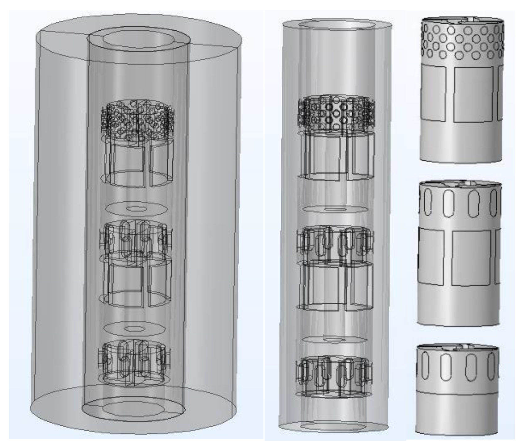
The main body of the modeling is the rotor and the cleaning tank (as shown in
Figure 1). The fluid is a mixture of oily sludge particles and water. The solid-liquid combination is a single flow continuum with density and viscosity. Two phases consist of a dispersed phase and a continuous phase.
The rotor has three layers of impellers, with slurry inlet under each layer of impeller and slurry outlet outside the impeller. When the rotor rotates at high speed, the fluid is sucked from the slurry inlet and jetted out from the slurry outlet. Oily sludge is cleaned by circulation to reduce the oil content of the sludge. The direction of fluid flow is opposite to the direction of the rotor impeller rotation.
In order to analyze the physical fields such as velocity field, pressure field, heat dissipation and cavitation generated by the stirring rotor during high-speed operation, the boundary conditions were set as follows: (1) the rotor speed was 6000 r/min; (2) oily sludge 800 g; (3) 1600 mL water; (4) the inlet pressure and outlet pressure were 1.013×10⁵ Pa. According to the boundary conditions, the rotor was simulated by mathematical model and reasonable calculation formula.
2.2. Governing Equations
The Mixture Model, k-ε interface solves one set of Navier–Stokes equations for the momentum of the mixture. The pressure distribution is calculated from a mixture averaged continuity equation and the velocity of the dispersed phase is described by a slip model. The volume fraction of the dispersed phase is tracked by solving a transport equation for the volume fraction. Turbulence effects are modeled using the standard two-equation k-ε model with realizability constraints. Flow close to walls is modeled using wall functions. The dispersed phase can be bubbles, liquid droplets, or solid particles, which are assumed to always travel with their terminal velocity.
In the Mixture Model interfaces the particle-fluid combination is regarded as a single flowing continuum with macroscopic properties such as density and viscosity. The two phases consist of one dispersed phase and one continuous phase. The mixture model is valid if the continuous phase is a liquid, and the dispersed phase consists of solid particles, liquid droplets, or gas bubbles. For gas bubbles in a liquid, however, the bubbly flow model is preferable. The mixture model relies on the following assumptions:
(1) The density of each phase is approximately constant.
(2) Both phases share the same pressure field.
(3) The particle relaxation time is short compared to the time-scales of the macroscopic flow.
The mixture density is given by
where:
and
denote the volume fractions of the continuous phase and the dispersed phase (SI unit: m
3/m
3), respectively;
is the continuous phase density (SI unit: kg/m
3);
is the dispersed phase density (SI unit: kg/m
3).
The mass-averaged mixture velocity u (SI unit: m/s), defined as
The volume flux for each phase is
where:
and
(SI unit: m/s) are the continuous and the dispersed phase velocity vectors, respectively.
The volume-averaged mixture velocity j (SI unit: m/s), defined as
It is assumed that the densities of both phases in the Mixture Model interfaces, ρ
c and ρ
d, are constant, and therefore the following alternative form of the continuity equation for the mixture is used
The momentum equation for the mixture is
where:
j is the velocity vector (SI unit: m/s);
is the density (SI unit: kg/m3);
P is the pressure (SI unit: Pa);
uslip is the slip velocity vector between the two phases (SI unit: m/s);
jslip is the slip flux (SI unit: m/s);
K is the sum of viscous stress and turbulent stresses (SI unit: kg/(m·s2));
Dmd is a turbulent dispersion coefficient (SI unit: kg/(m3·s));
g is the gravity vector (SI unit: m·s2);
F is any additional volume force (SI unit: N/m);
I is the identity matrix;
k is turbulent kinetic energy (SI unit: m2/s2);
µ is the dynamic viscosity (SI unit: Pa·s);
is the turbulent viscosity (SI unit: Pa·s);
The slip flux is defined for convenience as,
Here, (SI unit: m/s) denotes the relative velocity between the two phases.
The reduced density difference ε is given by
The turbulence must be accounted for in the calculation of the dispersed phase volume fraction. The turbulent dispersion coefficient
(SI unit: m
2/s) is
where
is the turbulent particle Schmidt number (dimensionless). The particle Schmidt number is usually suggested a value ranging from 0.35 to 0.7. In the physics interface the default value is 0.35.
The transport equation for
, the dispersed phase volume fraction is
where
(SI unit: kg/(m
3·s)) is the mass transfer rate from the dispersed to the continuous phase and
is a turbulent dispersion coefficient (SI unit: m
2/s).
The continuous phase volume fraction
is
The dispersed phase flux
(SI unit: m/s) is:
The dispersed phase velocity vector
is given by
Setting the Two-phase turbulence interface property to Mixture, the turbulence of the two-phase flow is modeled by solving the following
k and ε equations:
The equations correspond to the standard two-equation k-ε model including realizability constraints.
The production term is defined accordingly as
and the resulting turbulent viscosity is defined as
where
is a model constant.
2.3. Equation of boundary conditions
Not only the boundary conditions for the mixture are set, but also the boundary conditions for the dispersed phase are specified on the wall, inlet and outlet nodes.
The velocity component perpendicular to the wall is
where
is the friction velocity.
The shear stress condition is
where
is the friction velocity calculated by the shear stress of the wall;
is tangential wall velocity.
For a moving wall with translational velocity
, replace j in the equation with relative velocity:
, The velocity of the tangential wall is
For turbulent flow, turbulence variables are in general subject to homogeneous Neumann conditions
for the k-ε model.
The boundary conditions for
is:
where,
and
are constants;
is wall lift, expressed in viscous unit.
The dispersed phase flux in the normal direction is
2.4. Mesh Division
Accurate mesh division can improve the accuracy of simulation calculation. The mesh generator discretizes the domains into tetrahedral, hexahedral, prism, or pyramid mesh elements whose faces, edges, and corners are called mesh faces, mesh edges, and mesh vertices, respectively.
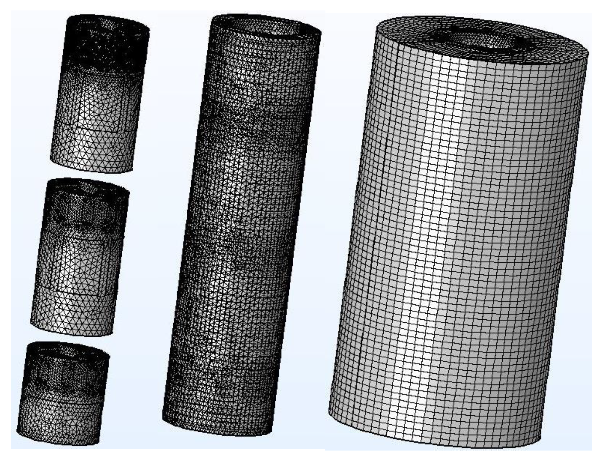
In order to facilitate calculations during the simulation, the three-dimensional model of the rotor was divided into three areas, namely, the inner area, the intermediate transition area and the outer area (
Figure 2).
The inner area consisted of 3 impellers, which were established as separate modules. Because the impeller rotates at high speed in the simulation process, the inner area was set as a dynamic mesh. Tetrahedral mesh was used in the intermediate transition area, which has the best geometrical adaptability. The outer area was relatively stable, using the swept mesh. A swept mesh is a semi-structured mesh since it is structured in the sweep direction and can be either structured or unstructured orthogonally to the sweep direction. The swept mesher operates on a 3D domain by meshing or reusing an existing mesh on a source face, and then sweeping the resulting face mesh along the domain to an opposite destination face. The swept mesh is typically a hexahedral mesh (hex mesh) or a prism mesh.
3. Simulation results and analysis
The COMSOL Multiphysics finite element analysis software was used to simulate the process of cleaning oily sludge by the high-speed stirring rotor. The distribution of physical phenomena such as velocity field, pressure field, heat dissipation and cavitation generated during the process of cleaning oily sludge by the high-speed stirring rotor was analyzed by simulation. The simulation results were reflected in the form of pictures. Through the simulation software and the information contained in the pictures, the simulation results of the velocity field, pressure field, heat dissipation and cavitation were analyzed.
3.1. Velocity field
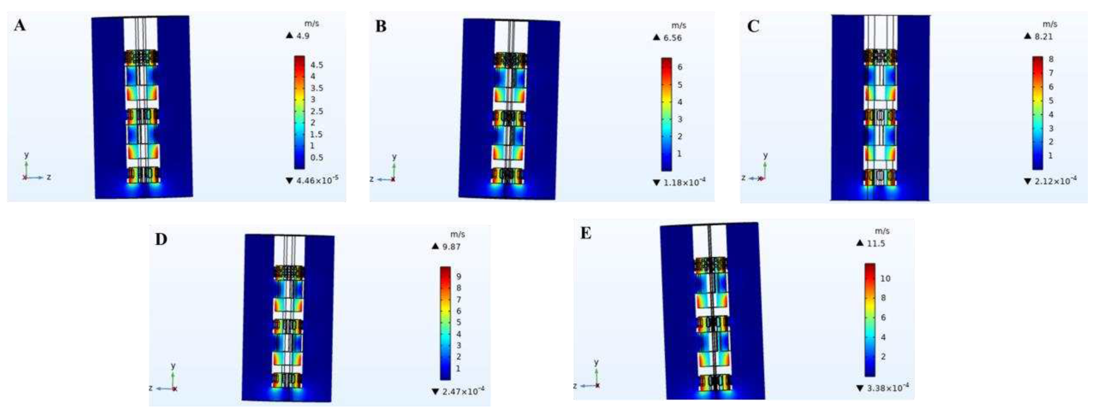
The simulation diagram of velocity field distribution in the cleaning process of high-speed stirring rotor was shown in
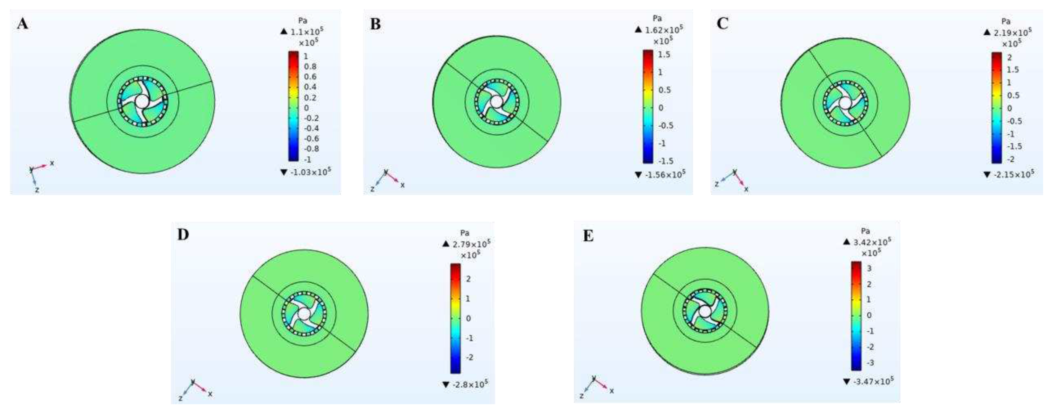
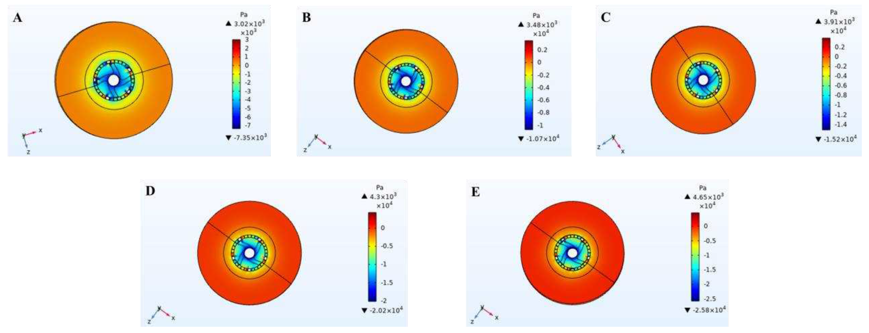
Figure 3. During the high-speed rotation of the stirred rotor, a strong velocity field was generated at the impeller. Along the axial center, the velocity increases gradually and reaches the maximum value at the blade tip. When the rotor keeps rotating at high speed under the action of high speed motor, the impeller and the area below it will generate negative pressure (as shown in
Figure 4 and
Figure 5). The slurry was sucked into the impeller from the slurry inlet hole because of the pressure change inside and outside the rotor. According to law of Newton’s viscosity,
where, τ-shear stress, Pa; μ-viscosity, Pa·s; u-impeller edge speed, m/s; h-clearance between impeller and inner rotor wall, m.
Equation (27) showed that the slurry was subjected to shear force at the rotor impeller, the shear force was positively correlated with the rotor speed of the rotor (Hu C Y et al., 2001; Li B Y et al., 2021). The slurry was sheared at the impeller at high speed, forming a strong hydraulic shear and turbulence. Under the centrifugation, grinding, collision, crushing and other comprehensive forces, sludge was fully broken, refined and separated. When the shear stress reaches or exceeds the oil/sludge adsorption force, the oil phase can be separated.
3.2. Pressure field
The simulation diagram at the impeller and slurry inlet hole of pressure distribution in the cleaning process of high-speed stirring rotor was shown in
Figure 4 and
Figure 5, respectively. The values of positive pressure and negative pressure increase with the increase of stirring rotor speed (as shown in
Figure 4 and
Figure 5). The negative pressure area was generated at the impeller and slurry inlet, which was mainly distributed in the front side of the blade and the whole area of the slurry inlet. The negative pressure at slurry inlet was largest.
Figure 5 showed the maximum negative pressure at the axis of the stirring rotor. The outside of the rotor was positive pressure, and the inside of the rotor was negative pressure. Because of the pressure change, the slurry was sucked into the impeller from the slurry inlet, and then thrown out from the slurry outlet by the strong centrifugal force after the strong stirring and shearing of the rotor. The slurry was cleaned by circulating stirring so that the oil phase in the slurry was desorbed and separated.
3.3. Heat Dissipation
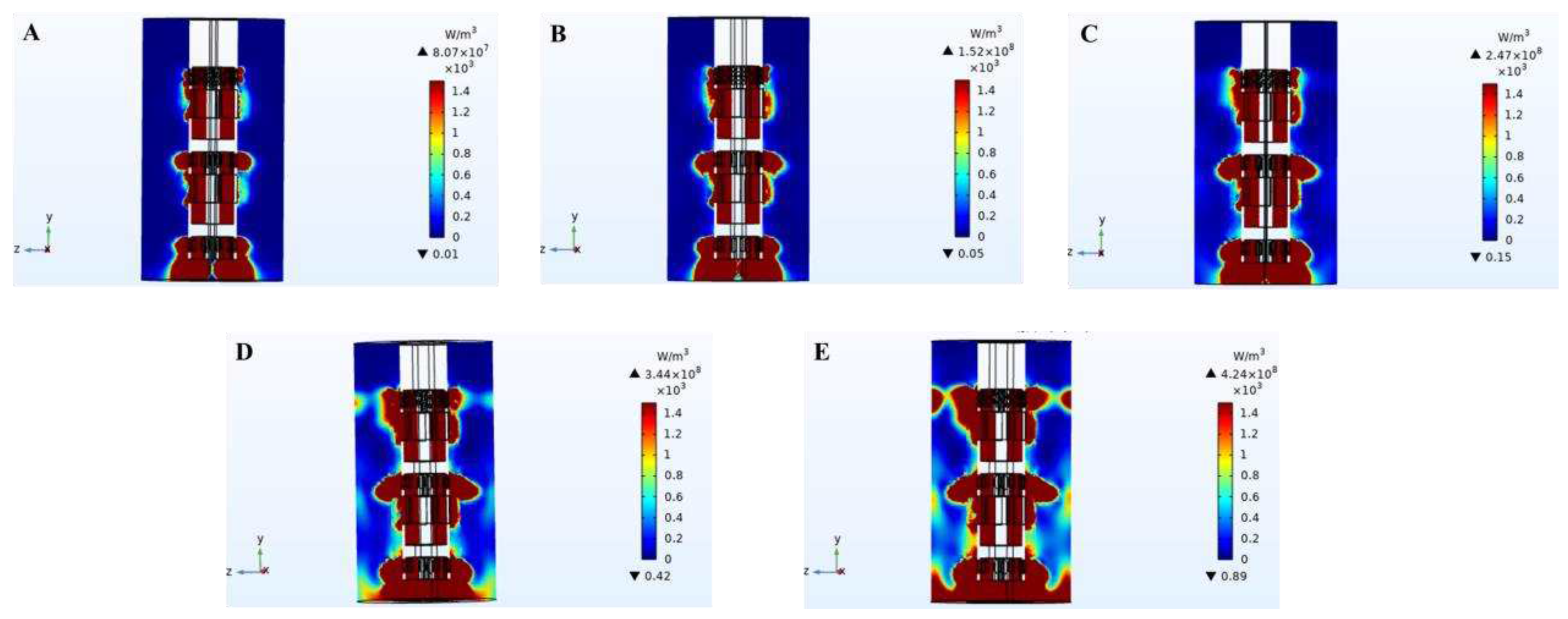
The simulation diagram of heat dissipation distribution in the cleaning process of high-speed stirring rotor was shown in
Figure 6. Heat was generated in the working area of the stirring rotor. Heat dissipation area and heat value increased with the increase of rotor speed. In the process of high-speed rotation of the stirred rotor, the heat was mainly generated from the following points: (1) friction between the slurry particles and impeller; (2) friction between slurry particles; (3) friction between slurry particles and rotor hole wall.
During the experiment, the slurry temperature increased significantly with the increase of the working time of the stirring rotor. The experimental phenomenon was the same as the simulation results. The heat generated in the cleaning process promotes the oily sludge treatment. The viscosity of the oil sludge will be reduced with the increase of temperature, which will make it easier to clean oily sludge and facilitate the separation of oil/sludge.
3.4. Cavitation
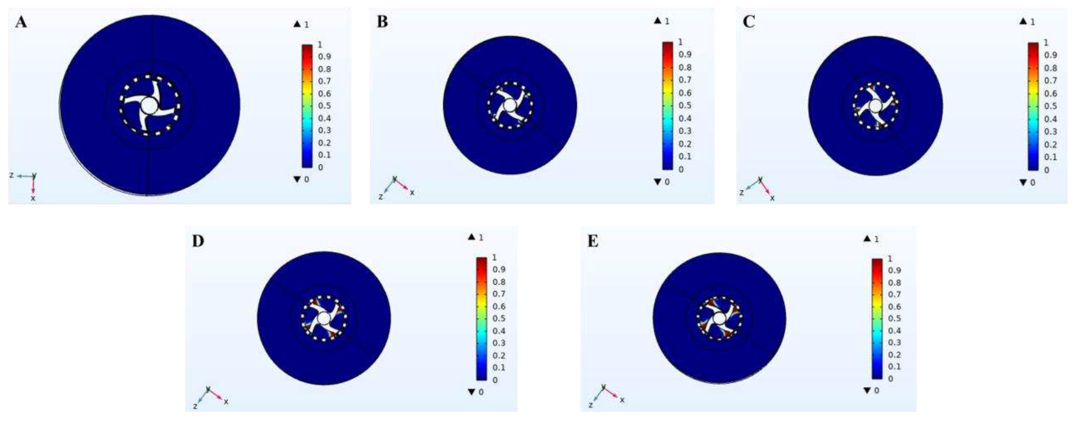
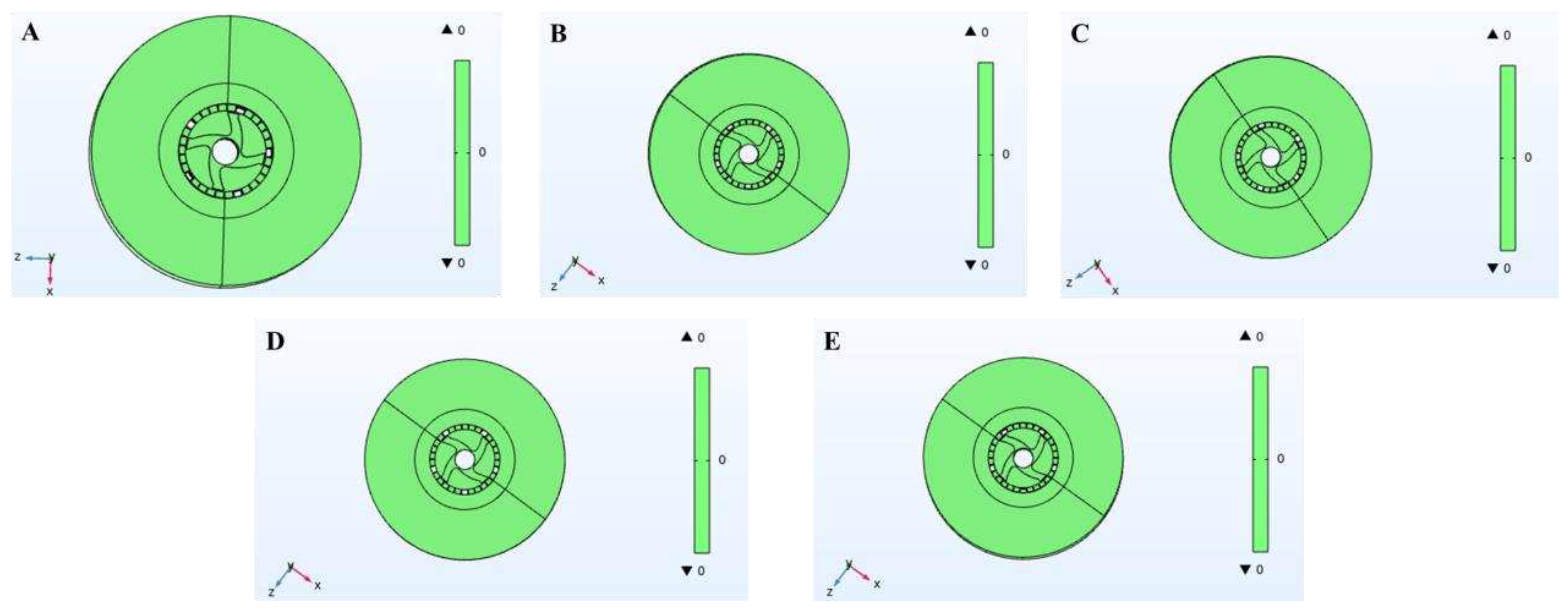
The simulation diagram at the impeller and slurry inlet hole of cavitation distribution in the cleaning process of high-speed stirring rotor was shown in
Figure 7 and
Figure 8, respectively. According to the comparison between
Figure 7 and
Figure 8, cavitation only occurs in the area near the blade tip of the impeller of the stirring rotor and the slurry outlet.
Figure 7 showed that cavitation occurs only when the rotor reaches a certain speed. When the rotor speed was 3000 r/min, there was no cavitation phenomenon. When the rotor speed exceeded 3000 r/min, cavitation phenomenon began to appear, and the distribution of cavitation phenomenon increased with the increase of rotor speed.
In the process of high-speed rotation of the rotor, the local pressure of the four blades of the impeller and the contact area of the slurry outlet was lower than the saturated steam pressure at the corresponding temperature, resulting in cavitation phenomenon and the formation of cavitation bubbles. The cavitation bubbles could float the separated oil to the surface of the slurry to separate the oil. In the process of oily sludge cleaning experiments, a large number of bubbles appeared, which verified the existence of cavitation phenomenon in the simulation, and the simulation results were consistent with the experimental phenomenon.
4. Discussion
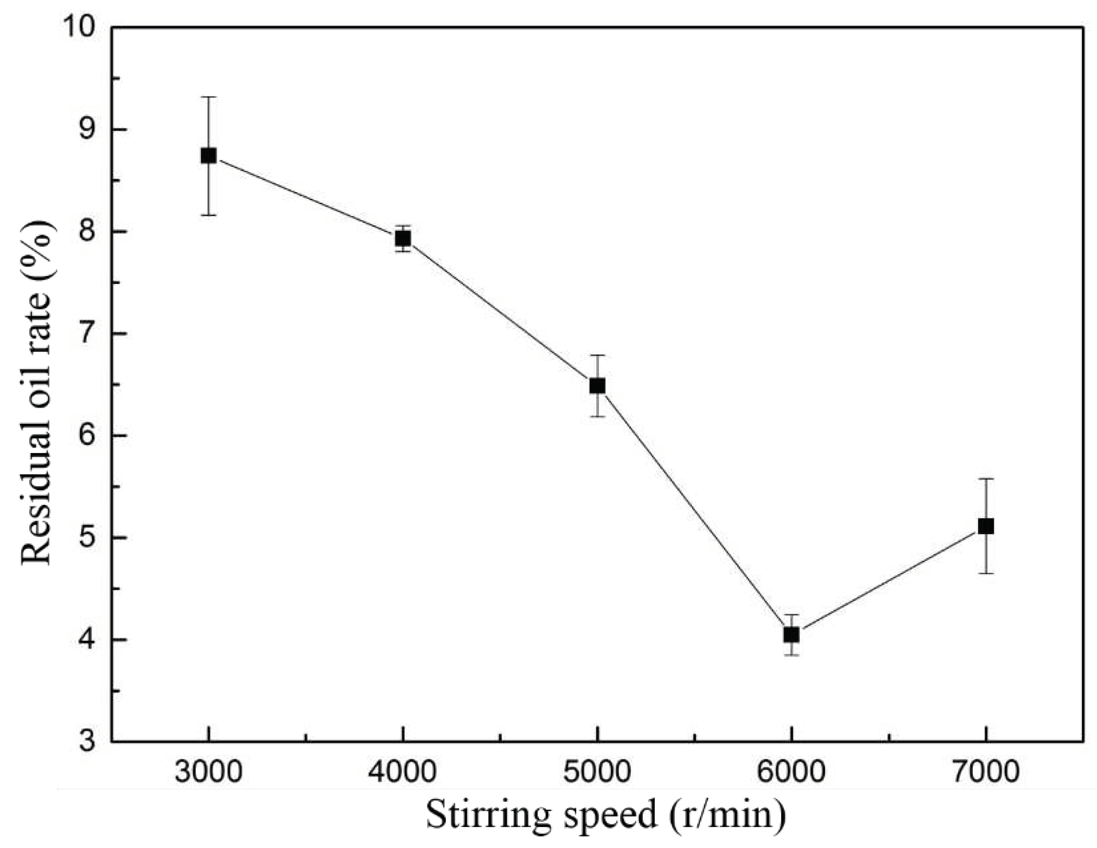
The simulation results were verified by experiments. The experimental conditions were as follows: 800 g oily sludge, 1600 mL water and a certain proportion of cleaning agent, cleaning time of 10 min. Three parallel samples were taken for each group of experiments. The initial oil content of oily sludge was 14.71%.
Figure 9 showed that when the rotor speed was 6000 r/min, the cleaning effect was the best, and the residual oil rate of the sludge was 4.03% after cleaning. According to the simulation results, when the rotor speed was 6000 r/min, the maximum positive pressure was 4.3×10
7 Pa, and the maximum negative pressure was -2.02×10
4 Pa. The maximum heat dissipation was 3.44×10
11 W/m
3. The distribution of cavitation mass fraction was well. Under these conditions, high speed stirring can effectively separate the oil from the sludge. When the stirring speed was higher than 6000 r/min, the shear force will be enhanced, leading to re-emulsification, which makes part of the separated oil recombine with the sludge, resulting in a gradual increase in the residual oil rate of the sludge (Zhu Y M et al., 2022).
During the process of oily sludge cleaning experiment, it can be intuitively seen that a large number of bubbles emerge from the slurry, which is the result of the cavitation phenomenon. The cavitation region can be clearly seen in the simulation results (as shown in
Figure 7). The oil separated from the solid particles floats to the surface of the slurry through bubbles. The floating oil can be recycled. At the same time, in the process of high-speed stirring cleaning, the temperature of the slurry can be obviously to increase with the increase of cleaning time. In the simulation results, we know that during the high-speed operation of the rotor, it generated a lot of heat, resulting in an increase in the temperature of the slurry (as shown in
Figure 6). The physical phenomena in the simulation results were verified by experiments.
5. Conclusions
In this paper, COMSOL Multiphysics finite element analysis software was used to simulate and evaluate the process of cleaning oily sludge by high-speed stirring rotor. The influence of the physical field produced by the rotor in the process of high-speed operation on the sludge cleaning effect was analyzed. At the same time, the simulation results were compared with experiments. The results showed that the shear force increased with the increase of rotor speed. When the shear force reached the adsorption force of oil/sludge, the oil in the sludge can be separated. If the rotational speed continues to increase, the shear force will be enhanced, leading to re-emulsification, which makes part of the separated oil recombine with the sludge, resulting in a gradual increase in the residual oil rate of the sludge. The pressure changes with the increase of rotor speed, resulting in a negative pressure area inside the rotor. The change of pressure leads to cavitation, which results in the formation of cavitation bubbles. The cavitation distribution increases with the increase of rotor speed. The cavitation bubble can play the role of air floating to float the separated oil to the upper surface for recovery. When the rotor is running at high speed, the slurry temperature rises because of the friction between particles and impeller, particles and particles, particles and rotor wall. The viscosity of the oil sludge will be reduced with the increase of temperature, which will make it easier to clean oily sludge and facilitate the separation of oil/sludge. The experimental results showed that the simulation results of shear force, negative pressure caused by high-speed rotation, cavitation phenomenon and heat generated by friction were the same as the experimental results. The method described in this article can effectively treat oily sludge, which make oily sludge reduced, resourceful, and harmless, and contribute to the sustainable development of the ecological environment.
Funding
This research was supported by the Fundamental Research Funds for the Central Universities (No. 3132023518).
Acknowledgement
The authors would like to thank the other partners in our group for their contributions to this work.
Declaration of Conflicting Interests
The author(s) declared no potential conflicts of interest with respect to the research, authorship and/or publication of this article.
References
- Breyer, S.; Mekhitarian, L. Production of an alternative fuel by the co-pyrolysis of landfill recovered plastic wastes and used lubrication oils. Waste Management 2017, 60, 363–374. [Google Scholar] [CrossRef] [PubMed]
- Yanlin, W.; Lei, L.; Zhigang, Y.; Ziqi, G. Advances on Recycling Technique for Oily Sludge. Oilfield Chemistry 2015, 32, 151–153. [Google Scholar]
- Wang, Y.H.; Zhang, X.M.; Pan, Y.Y.; Chen, Y. Analysis of oil content in drying petroleum sludge of tank bottom. Int J Hydrog Energy 2017, 42, 18681–18684. [Google Scholar] [CrossRef]
- Adetutu, E.M.; Bird, C.; Kadali, K.K. Exploiting the intrinsic hydrocarbon-degrading microbial capacities in oil tank bottom sludge and waste soil for sludge bioremediation. International Journal of Environmental Science and Technology 2015, 12, 1427–1436. [Google Scholar] [CrossRef]
- Cerqueira, V.S.; Hollenbach, E.B.; Maboni, F.; Vainstein, M.H.; Camargo, F.A.O.; Peralba, M.D.R.; Bento, F.M. Biodegradation potential of oily sludge by pure and mixed bacterial cultures. Bioresource Technology 2011, 102, 11003–11010. [Google Scholar] [CrossRef]
- Hu, G.; Li, J.; Thring, R.W.; Arocena, J. Ultrasonic oil recovery and salt removal from refinery tank bottom sludge. Journal of Environmental Science & Health Part A Toxic /hazardous Substances & Environmental Engineering 2014, 49, 1425–1435. [Google Scholar] [CrossRef]
- Liu, F.W.Q.; Qu, T.Y.; Zhang, Y. Technical progress in the treatment of oil⁃bearing sludge in refineries. Industrial Water Treatment 2017, 37, 1–5. [Google Scholar]
- Leonard, S.A.; Stegemann, J.A. Stabilization /solidification of petroleum drill cuttings. Journal of Hazardous Materials 2010, 174, 484–491. [Google Scholar] [CrossRef]
- Gazineu MH, P.; de Araujo, A.A.; Brandao, Y.B.; Hazin, C.A.; Godoy JM, D. Radioactivity concentration in liquid and solid phases of scale and sludge generated in the petroleum industry. J. Environ. Radioact. 2005, 81, 47–54. [Google Scholar] [CrossRef]
- Cambiella, A.; Benito, J.M.; Pazos, C.; Coca, J.; et al. Centrifugal separation efficiency in the treatment of waste emulsified oils. Chem. Eng. Res. Des. 2006, 84, 69–76. [Google Scholar] [CrossRef]
- Jasmine, J.; Mukherji, S. Impact of bioremediation strategies on slurry phase treatment of aged oily sludge from a refinery. Journal of Environmental Management 2019, 246, 625–635. [Google Scholar] [CrossRef] [PubMed]
- Roldan-Carrillo, T.; Castorena-Cortes, G.; Zapata-Penasco, I.; Reyes-Avila, J.; Olguin-Lora, P. Aerobic biodegradation of sludge with high hydrocarbon content generated by a Mexican natural gas processing facility. Journal of Environmental Managemen 2012, 95, S93–S98. [Google Scholar] [CrossRef] [PubMed]
- Jing, G.; Chen, T.; Luan, M. Studying oily sludge treatment by thermo chemistry. Arabian J. Chem. published online Jun 15, 2011. [CrossRef]
- Chen, G.; Cheng, C.; Zhang, J.; Sun, Y.; Hu, Q.; Qu, C.; Dong, S.B. Synergistic effect of surfactant and alkali on the treatment of oil sludge. J. Pet. Sci. Eng. 2019, 183, 106420–106428. [Google Scholar] [CrossRef]
- Duan, M.; Wang, X.; Fang, S.; Bo, Z.; Li, C.; Xiong, Y. Treatment of Daqing oily sludge by thermochemical cleaning method. Colloids Surf., A 2018, 554, 272–278. [Google Scholar] [CrossRef]
- Li, X.B.; Liu, J.T.; Xiao, Y.Q.; Xiao, X. Modification technology for separation of oily sludge. J. Cent. South Univ. Technol. (Engl. Ed.) 2011, 18, 367. [Google Scholar] [CrossRef]
- Zhu, Y. M.; Li, K. Q.; Wang, Y.; Zhao, J.; Tang, X.J.; Li, T.; Zhang, C.M. Highly Efficient Treatment of Oily Sludge by a Novel High-Speed Stirring Method at Room Temperature. Int. J. Environ. Res. Public Health 2022, 19, 16817. [Google Scholar] [CrossRef]
- Wegner, J.; Ganzer, L. 2012 Numerical simulation of oil recovery by polymer injection using COMSOL. In: Excerpt from the Proceedings of the 2012 COMSOL Conference in Milan, Milan.
- Sharma, P.; Kumar, S.S.; Nashine, B.; Veerasamy, R.; Krishnakumar, B.; Kalyanasundaram, P.; Vaidyanathan, G. Development, computer simulation and performance testing in sodium of an eddy current flowmeter. Ann Nucl Energy 2010, 37, 332–338. [Google Scholar] [CrossRef]
- Xu, Y.C.; Zhang, K.H.; Lu, S.; Liu, Z.Q. Experimental investigations into abrasive flow machining of helical gear. Digital Design and Manufacturing Technology III 2013, 546, 65–69. [Google Scholar] [CrossRef]
- Baghel, R.; Kalla, S.; Upadhyaya, S.; Chaurasia, S.P.; Singh, K. CFD modeling of vacuum membrane distillation for removal of Naphthol blue black dye from aqueous solution using COMSOL multiphysics. Chemical Engineering Research and Design 2020, 158, 77–78. [Google Scholar] [CrossRef]
- Kim, J.H.; Seo, H.S.; Kim, Y.J. Thermal-Flow Characteristics of Ferrofluids in a Rotating Eccentric Cylinder under External Magnetic Force. Micromachines 2018, 9, 1–8. [Google Scholar] [CrossRef] [PubMed]
- Sutkar, V.S.; Gogate, P.R.; Csoka, L. Theoretical prediction of cavitational activity distribution in sonochemical reactors. Chemical Engineering Journal 2010, 158, 290–295. [Google Scholar] [CrossRef]
- Hu, C.Y. Study on Homogenous Criterion of Turbulence Flow in High-shearing Homogenizer. Packing and Food Machinery 2001, 19, 11–14. [Google Scholar]
- Li, B.Y.; Liu, D.C.; Yin, T.; He, H.B.; Tang, X. Study on the relationships between linear velocity and shear force on the particle size distribution of coarse emulsion. Chinese Journal of Pharmaceutics 2021, 19, 67–73. [Google Scholar]
|
Disclaimer/Publisher’s Note: The statements, opinions and data contained in all publications are solely those of the individual author(s) and contributor(s) and not of MDPI and/or the editor(s). MDPI and/or the editor(s) disclaim responsibility for any injury to people or property resulting from any ideas, methods, instructions or products referred to in the content. |
© 2023 by the authors. Licensee MDPI, Basel, Switzerland. This article is an open access article distributed under the terms and conditions of the Creative Commons Attribution (CC BY) license (http://creativecommons.org/licenses/by/4.0/).
