Preprint
Article

Efficient and Stable Air-Processed Ternary Organic Solar Cells Incorporating Gallium-Porphyrin as Electron Cascade Material

Altmetrics

Downloads

124

Views

77

Comments

0

A peer-reviewed article of this preprint also exists.

Submitted:

04 August 2023

Posted:

08 August 2023

You are already at the latest version

Alerts
Abstract
Two gallium porphyrins, a tetraphenyl GaCl porphyrin, termed as (TPP)GaCl, and an octaethylporphyrin GaCl porphyrin, termed as (OEP)GaCl were synthesized to use as electron cascade in ternary organic bulk heterojunction films. A perfect matching of both gallium porphyrins energy levels with that of poly(3-hexylthiophene-2,5-diyl) (P3HT) or poly[N-9′-heptadecanyl-2,7-carbazole-alt-5,5-(4′,7′-di-2-thienyl-2′,1′,3′-benzothiadiazole)] (PCDTBT) polymer donor and the 6,6-phenyl C71 butyric acid methyl ester (PCBM) fullerene acceptor forming an efficient cascade system that could facilitate electron transfer between donor and acceptor was demonstrated. Therefore, ternary organic solar cells (OSCs) using the two porphyrins in various concentration were fabricated, where a performance enhancement was obtained. In particular, (TPP)GaCl-based ternary OSCs of low concentration (1:0.05 vv%) exhibited a ~17 % increase of the power conversion efficiency (PCE) compared with the binary device due to improved exciton dissociation, electron transport and reduced recombination. On the other hand, ternary OSCs with the (TPP)GaCl of high concentration (1:0.1 vv%) and (OEP)GaCl (1:0.05 and 1:0.1 vv%) showed poorest efficiencies due to very rough nanomorphology and suppressed crystallinity of ternary films when the GaCl porphyrin introduced in the blend, as revealed from X-ray diffraction (XRD) and atomic force microscopy (AFM). The best performed devices exhibited also improved photostability, when exposed to sunlight illumination for a period of 8 h than the binary OSCs, attributed to the suppressed photodegradation of the ternary (TPP)GaCl 1:0.05-based photoactive film.
Keywords: 
Subject: Engineering  -   Energy and Fuel Technology

1. Introduction

Today’s energy crisis has caused a shock of unprecedented breadth and intricacy leading to the evaluation of renewable energy opportunities that meet the continuous electricity demand. Hence, exploiting solar energy for power generation has become even more imperative nowadays shaping the photovoltaic research landscape [1,2,3,4,5,6]. Given the significance of briskly diversifying our energy supply and enhancing energy efficiency, overcoming the hurdles concerning the global, organic solar cell (OSC) promotion should be a priority for all interested parties involved from academics and publishers to companies and funding agencies. Among different photovoltaic technologies, OSCs are thin-filmed solar cells with unique features for either outdoor [7,8,9] or indoor use [10,11,12,13,14]. The possibility of their application for large area coverage [15,16,17,18], their semitransparent character [19,20,21], and low cost fabrication by printing methods [18, 22–24], enable OSCs to integrate into buildings facades and windows or sunroofs. In this way, OSCs can provide energy derived from sunlight that might either warm a room or contribute to power electric (i.e hybrid vehicles). [25,26,27,28]. What’s more, due to their lightweight nature [29,30], flexibility [31,32] and coloration [33], OSCs can be an affordable solution for delivering smaller quantities of electricity required for wearable [34,35,36] and portable electronics [37]. On the other hand, indoor OSCs appear to have great application potential in Internet-of-Things [38,39] and energy harvesting [40,41].
Undoubtedly, OSCs provide the momentum for a large number of technological applications. In recent years, sustained research efforts have notably increased the solar to electrical power-conversion efficiencies of OSCs to a satisfying level for them to be brought to market. The most efficient semitransparent OSC yielded power conversion efficiency (PCE) of 19% [42], while also the record high efficiency of 28% for indoor OSC has been reported [43]. Nevertheless, despite the fact that OSCs have reached the performance of their predecessors, unfortunately their commercialization is restricted by stability issues. Instability in OSCs is dictated by a series of degradation modes that are usually assigned to the stability of individual materials or interfaces [44,45,46,47]. For instance, many organic compounds are chemically degraded when constantly irradiated mainly owing to their susceptibility to atmospheric oxygen [48] and moisture [49]. Additionally, morphological degradation may occur under extreme environmental conditions such as extended light exposure and elevated temperatures. Climate variability that meet outdoor operation can lead to the diffusion of buffer layers and electrodes and especially to the evolution of the phase segregated bulk-heterojunction (BHJ) active layer due to the strong mobility of organic materials, stressing the cell and eventually causing its decaying performance [44,50]
It is well-known that ideal active layer morphology, aside from having a favorable molecular orientation to optimize charge transport and being compositionally structured in vertical direction to facilitate charge collection, should form a bicontinuous network of mixed nanodomains of semiconducting materials for efficient exciton dissociation and suppression of charge recombination, simultaneously [51,52,53,54,55]. Accordingly, the morphology of active layers plays a pivotal role in impacting the overall photovoltaic performance. While many strategies including material optimization [56], device engineering [57] and encapsulation processes [58] have been proposed to improve and stabilize active layer morphology, structural engineering is identified as strategic priority. In this context, numerous reports have come up that focus on designing effective additives to enhance electronic and/or morphological properties of typical OSC systems with the commonly used poly(3-hexylthiophene) (P3HT) and phenyl-C61-butyric acid methyl ester (PC61BM) as donor and acceptor, respectively [59,60,61,62].
The approach of adding a third component to form ternary BHJ blends for solar cells entails some specific intermolecular interactions in terms of controlling morphology. The third component should also act as a cascade layer reducing the charge transfer energy offsets at the door/acceptor lowest unoccupied molecular orbital (LUMO) levels, resulting in reduced recombination losses. In addition, the cascade material should have excellent electron acceptor and transport properties for the case of the formation of a heterojunction between the third component and the donor-polymer. In this vein, porphyrins appear to be suitable candidates as component of functional BHJ additives. Owing to their strong absorption properties (high extinction coefficients) in both the blue (~400-550 nm, Soret or B-band) and red (~700-900 nm, Q-band) region of the visible spectrum, their high thermal stability and their remarkable electron transfer capability, porphyrins have been successfully applied in organic and planar perovskite solar cells as cathode interfacial modifiers realizing efficient device operation and longevity [63, 64]. Following this thinking, porphyrins could be introduced as a cascade energy material in a binary BHJ blend inducing efficient charge extraction as they can provide more efficient charge transport pathways [65]. Herein, we demonstrate the effect of two gallium porphyrins, tetraphenyl GaCl porphyrin, termed as (TPP)GaCl, and an octaethylporphyrin GaCl porphyrin, termed as (OEP)GaCl in various ratios, as additives in two different binary photoactive blends. The organic blends are consistent of poly(3-hexylthiophene-2,5-diyl) (P3HT) or poly[N-9′-heptadecanyl-2,7-carbazole-alt-5,5-(4′,7′-di-2-thienyl-2′,1′,3′-benzothiadiazole)] (PCDTBT) polymer donors with the 6,6-phenyl C71 butyric acid methyl ester (PCBM) fullerene acceptor. In this study, photophysical properties of the target porphyrins, alone and within the binary host BHJ blends were studied by mean of optical spectroscopy, while Fourier-transform infrared (FTIR) spectroscopy was used to analyze the chemical composition in every case and the possible interaction between the three components of the ternary films. Additionally, electrochemical characterization of the porphyrin compounds was performed to estimate the highest occupied molecular orbital (HOMO) and lowest unoccupied molecular orbital (LUMO) levels of the two porphyrins, revealing the potential role of GaCl porphyrins as electron cascade materials. Therefore, ternary organic solar cells using both porphyrins as the third component inserted in the PCDTBT:PCBM or P3HT:PCBM binary blend in various concentrations were fabricated. Note that all ternary and binary OSCs were prepared in air (without using glove box) to promote low-cost fabrication procedure. The addition of (TPP)GaCl with low concentration (1:0.05 vv%, see experimental sections for more details) increased by ~17 % the PCE of the ternary OSCs in comparison with the efficiency of the binary devices, which assigned to the enhanced electron transport and exciton dissociation into free charges, along with the reduced recombination. On the other hand, when (TPP)GaCl with higher concentration or (OEP)GaCl was added in the ternary film, rougher morphology surface and suppressed crystallinity were observed leading to poor PCE values of the corresponding ternary OSCs. Ternary (TPP)GaCl 1:0.05 vv%-based OSC exhibited also enhanced photostability under exposure to sunlight illumination for a period of 8 h, attributed to the better structural stability of the ternary films than the binary layer.

2. Results and discussion

2.1. Characterization of (TPP)GaCl and (OEP)GaCl porphyrin materials

Prior to the incorporation of the porphyrins as a third component in the binary blends P3HT:PCBM and PCDTBT:PCBM, their optical and electrochemical properties, were investigated. It should be mentioned that these molecules were selected due to their fine solubility in the same organic solvent of the organic blends[66]. The molecular structure of the gallium porphyrins featured in this study are shown in Figure 1a and their Fourier-transform infrared and UV-Vis absorption spectra are displayed in Figure 1b and 1c, respectively. The (TPP)GaCl porphyrin constitutes of four phenyl (C₆H₅) groups attached to the pyrrole rings, while in the (OEP)GaCl porphyrin’s structure, each of the pyrrole rings is substituted by ethyl groups [67].
In the FTIR transmittance spectrum of the (TPP)GaCl, weak peaks at around 3050 cm-1 corresponding to the C-H stretching vibrations of aromatic groups are observed. Moreover, peaks at 1107 cm-1 and 802 cm-1 are attributed to C-H scissoring of phenyl rings and out of plane bending mode of pyrrole rings, respectively, while peaks at 701 cm-1 and 754 cm-1 are assigned to out of plane bending of phenyl rings. In the area from 1347 cm-1 to 1600 cm-1, multiple peaks corresponding to stretching vibration of C=C aromatic groups of phenyl are observed, while in the 1206-1175 cm-1 region the stretching mode of C=N in pyrrole rings is appeared. The peak of Ga-Cl bond is not observed in the spectrum, since it can be found in the region 330-370 cm-1 [68], which are out of the range of our FTIR instrument. On the other hand, in the FTIR spectrum of (OEP)GaCl, the C=C stretching mode of phenyl rings and C-N stretching mode of pyrrole groups are detected at the1300-1580 cm-1 region and at 1150 cm-1, respectively. The bands ascribed to the substitution of the pyrrole unit correspond to the vibration modes of the ethyl group. Specifically, those peaks are found at 2966 cm-1, 2930 cm-1 and 2869 cm-1 (C-H stretching), at the 1160-960 cm-1 region (C-H bending), at 842 cm-1 (C-H out-of-plane bending) and at 749 cm-1 (rocking mode of CH2 group).
Figure 1c shows the UV-Vis absorption spectra of both porphyrins spin-coated on a glass from a chloroform solution with concentration of 1mg ml-1. It is observed that both gallium porphyrins exhibit typical Soret bands in the range of 375-475 nm and the Q-bands are all located at 515-625 nm revealing further electronic transitions in molecular orbitals. In particular, (TPP)GaCl porphyrin exhibits a sharper Soret band centered at 438 nm and two weak Q bands at 555 and 595 nm, while (OEP)GaCl porphyrin has a broader Soret band located at 413 nm and two Q bands at 541 and 577 nm.
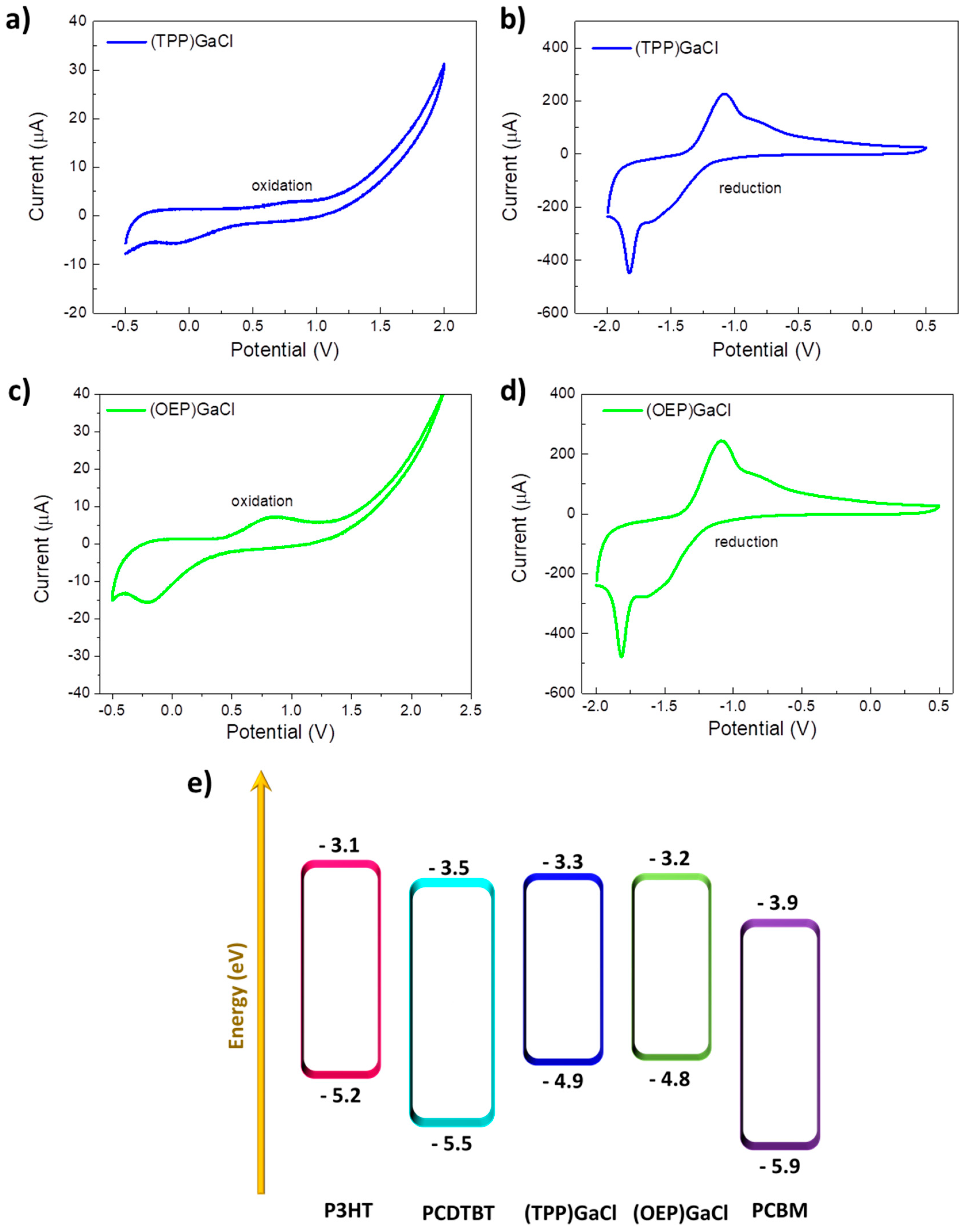
In order to examine the possible use of these porphyrin compounds as electron cascade in BHJ blends, their energy levels (EHOMO and ELUMO) were estimated performing cyclic voltammetry. Figure 2a-d shows the cyclic voltammograms of (TPP)GaCl and (OEP)GaCl porphyrins deposited on indium-tin oxide (ITO)/glass substrates. Oxidation and reduction potentials are summarized in Table 1 together with the estimation of the corresponding HOMO and LUMO levels evaluated by using the following empirical formulas [69]:
EHOMO = – (Eox,onset + 4.4) eV
ELUMO = – (Ered,onset + 4.4) eV
where Eox,onset and Ered,onset are the oxidation and reduction potential onsets, respectively, defined as the position where the current starts to differ from the baseline. From the cyclic voltammograms the Eox,onset value is +0.5 V and +0.4 V for (TTP)GaCl and (OEP)GaCl, respectively, which results in HOMO levels of –4.9 eV for (TTP)GaCl and –4.8 eV for (OEP)GaCl. The LUMO levels of (TTP)GaCl and (OEP)GaCl are –3.3 eV and –3.2 eV, respectively, determined by the reduction potential onset (–1.1 V for (TTP)GaCl and –1.2 V for (OEP)GaCl). The energy diagram illustrated in Figure 2e reveals the perfect matching of both gallium porphyrins energy levels with that of polymer donors (PCDTBT or P3HT) and PCBM-acceptor forming an efficient cascade system that could facilitate electron transfer between donor and acceptor.

2.2. Characterization of ternary blend films

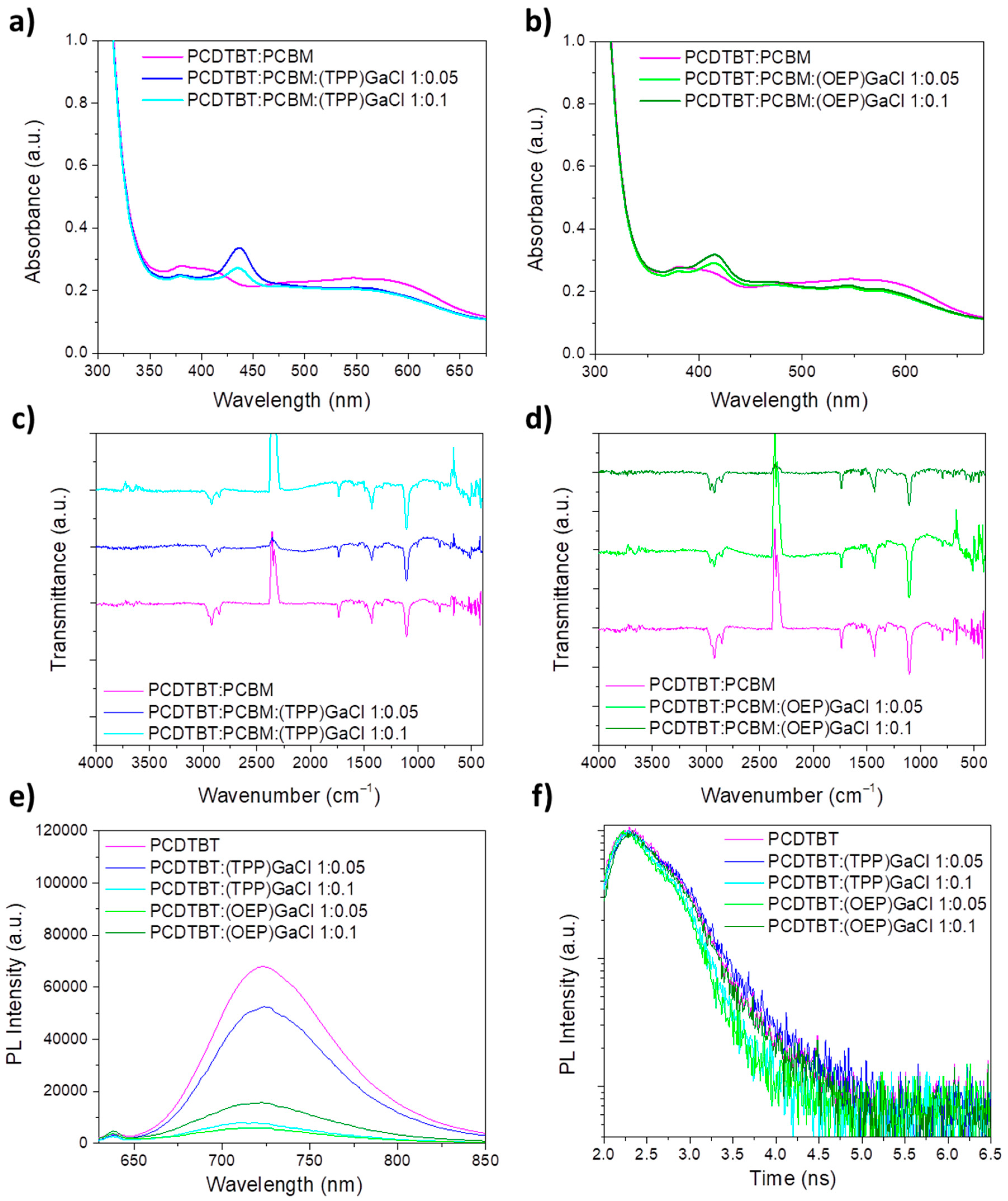
Figure 3a and b and Figure S1a and b presents the UV-Vis absorption spectra of ternary PCDTBT:PCBM:Ga-porphyrin and P3HT:PCBM:Ga-porphyrin films, respectively, forming on a glass substrate from a chloroform solution, as described in the Experimental Section. The binary PCDTBT:PCBM and P3HT:PCBM are also shown for comparison reasons. UV-Vis absorption spectra of the PCDTBT:PCBM film display a peak centered at 381 nm and a broad absorption band from 500 nm to 640 nm (Figure 3a-b), while P3HT:PCBM spectrum exhibits three absorption regions of P3HT at 501 nm, 545 nm, and 597 nm and extends into the visible region from approximately 400 nm to 700 nm (Figure S1a-b). In the spectra of the ternary films the peak corresponding of the Soret band of both porphyrin compounds is clearly seen. Moreover, a blue shift of PCDTBT:PCBM and P3HT:PCBM spectra is observed, when (TTP)GaCl and (OEP)GaCl porphyrins are incorporated into binary blends, which is more pronounced in the case of the (OEP)GaCl-based ternary films, and especially in the P3HT:PCBM:GaCl.
In order to investigate the chemical structure of the prepared ternary films, FTIR transmittamce measurements were performed. In the FTIR spectra of PCDTBT:PCBM:(TPP):GaCl shown in Figure 3c, a combination of peaks attributed to all three components of the ternary film are observed. In particular, the peaks at 2925 cm-1, 2852 cm-1 (C-H stretch), at 1739 cm-1 (C=O stretch), at 1494 cm-1 (C=C stretch), in the region 1430-1330 cm-1 (CH2 and CH3 bend), at 1250 cm-1 (C-O stretch) and at 1106 cm-1 (C-O bend) are assigned to the binary PCDTBT:PCBM blend. The only apparent (TPP)GaCl absorption band in the ternary film is detected in the aromatic stretching region, which can be seen in the spectrum of sample with 1:0.1 vv% ratio. In addition, the pyrrole breathing oscillation peak is detected at 1007 cm-1. Also, some weak peaks under 1000 cm-1, corresponding to the porphyrins are apparent (802, 754 and 701 cm-1). On the other hand, the porphyrin peaks located at 3050 cm-1, in the 1206-1175 cm-1 region and in the 1107-1110 cm-1 region cannot be observed in the ternary film, due to the low concentration of the (TPP)GaCl porphyrin with respect to the binary blend. Similarly, in the case of PCDTBT:PCBM:(OEP)GaCl (Figure 3d), the C-H stretching peaks just below 3000 cm-1, located at 2966, 2925 and 2852 cm-1 are a combination of the peaks from the binary blend and the porphyrin additive corresponding to the same vibration mode. The carbonyl peak at 1739 cm-1 remains unchanged, while the C=C stretching peaks of the porphyrin overlap with all other polymer blend peaks found in the region, more specifically at 1494 cm-1 (C=C stretch), 1430-1330 cm-1 (CH2 and CH3 bend) and 1250 cm-1 (C-O stretch). Just below this region, the C-O bending peak a 1106 cm-1 can be seen, while the C-N stretching peak of the porphyrin is absent from the ternary film. Furthermore, porphyrin weak peaks at 1160-960 cm-1 (C-H bend ethyl) are depicted. Same results can be also concluded for the ternary P3HT:PCBM:(TPP)GaCl and P3HT:PCBM:(OEP)GaCl ternary films, the FTIR transmittance spectra of which are shown in Figure S1c and d, respectively.
Moreover, photoluminescence (PL) measurements were applied to probe the efficiency of exciton dissociation and charge transfer. Figure 3e-f and Figure 3S1e-f illustrate the photoluminescence steady state emission (PL) spectra of various samples, including pristine films and blends of PCDTBT and P3HT with (TPP)GaCl and (OEP)GaCl in ratios of 1:0.05 and 1:0.1. In the PL spectrum of the pure P3HT film, a peak corresponding to excitonic emission is observed at 653 nm (Figure S1e). Upon introducing (TPP)GaCl to the P3HT blend, the PL intensity decreases, indicating an enhanced electron injection rate from P3HT to (TPP)GaCl and efficient suppression of electron-hole recombination. On the other hand, the addition of (OEP)GaCl results in increased fluorescence of P3HT, potentially attributable to the aggregation of (OEP)GaCl molecules. Additionally, a shift towards longer wavelengths (redshift) is noted in the PL spectrum of P3HT, particularly at higher concentrations of (OEP)GaCl. This shift may be ascribed to the presence of trapped states within the energy gap of (OEP)GaCl, aligning with the lowest energy states in the highest occupied molecular orbital (HOMO) of P3HT. Consequently, notable recombination occurs between photoinduced holes originating from the lowest HOMO states of P3HT and deep traps of (OEP)GaCl, along with enhanced photoinduced electron back transfer from the LUMO to the HOMO of P3HT.
Figure 3e shows the PL spectra of the PCDTBT and PCDTBT:(TPP)GaCl films demonstrating a significant decrease in emitted light intensity as the porphyrin concentration increases. Adding (TPP)GaCl in a ratio of 1:0.05 vv% reduces the fluorescence intensity of the PCDTBT film by 30 %, and with a ratio of 1:0.1 vv%, the fluorescence is almost completely suppressed by 88 %. The most pronounced quenching occurs with (OEP)GaCl, likely due to the aggregation of its molecules, which serves as an additional factor in reducing the fluorescence. However, despite the quenching effect, a shift towards shorter wavelengths (blue shift) is observed in the PCDTBT emission spectrum after incorporating the porphyrins. This shift could be attributed to the mitigation of charge carrier trapping states within the porphyrin, resulting in a modified emission for PCDTBT. Furthermore, time-resolved PL (TRPL) measurements presented in Figure 3f for the PCDTBT:(TPP)GaCl and PCDTBT:(OEP)GaCl shows shorter exciton life time suggesting the faster exciton dissociation, especially in the case of PCDTBT:(TPP)GaCl 1:0.1 and PCDTBT:(OEP)GaCl 1:0.05 samples. In the case of P3HT blended with the two GaCl-porphyrins (Figure S1f), short exciton lifetime facilitating exciton dissociation exhibits only the P3HT:(TPP)GaCl film.
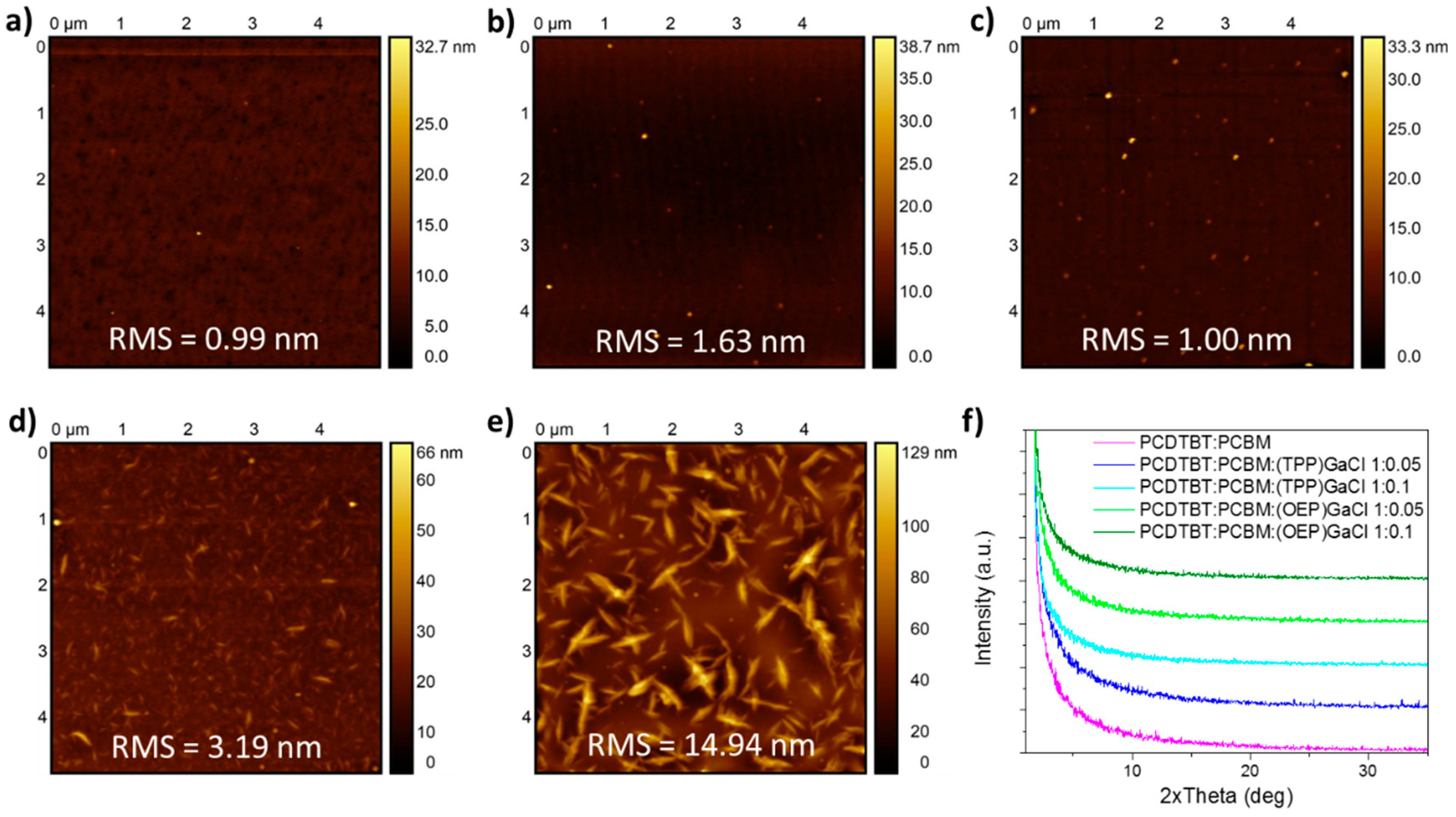
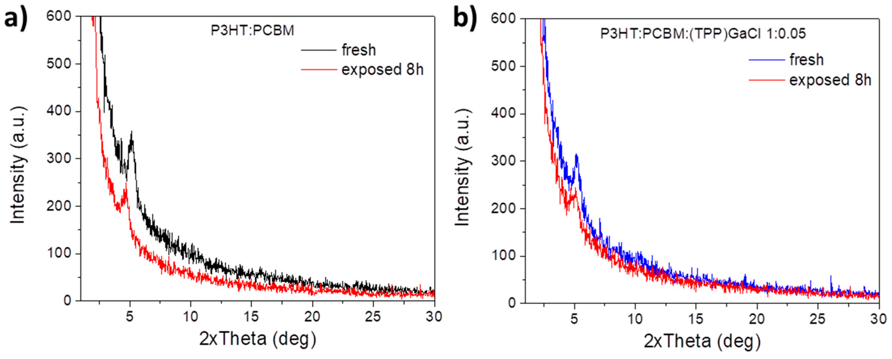
In order to study the surface nanomorphology of the ternary films, atomic force microscopy (AFM) measurements were performed. Figure 4 and Figure S2 depict the 5x5 μm2 surface topographic AFM image of pristine PCDTBT:PCBM and P3HT:PCBM films, respectively, as well as the films of these photoactive blends modified with (TPP)GaCl and (OEP)GaCl in ratios of 1:0.05 and 1:0.1. AFM analysis of the PCDTBT:PCBM film (Figure 4a) revealed that the introduction of (TPP)GaCl in both concentrations (1:0.05 and 1:0.1) slightly changed the surface roughness of the samples exhibiting root mean square (RMS) roughness of 1.63 nm and 1.00 nm for the PCDTBT:PCBM:(TPP)GaCl 1:0.5 (Figure 4b) and PCDTBT:PCBM:(TPP)GaCl 1:0.1 (Figure 4(c)), respectively, compared with the RMS=0.99 of the binary film. However, small grains of few nanometers, which may be assigned to the porphyrin compound, are observed on the surface of the ternary films. On the other hand, the nanomorphology of the ternary films based on the (OEP)GaCl porphyrin is significantly changed. The surface of the PCDTBT:PCBM:(OEP)GaCl (Figure 4d and e) consists of large domains, with size ~500 nm for the PCDTBT:PCBM:(OEP)GaCl 1:0.1 and RMS=14.94 nm. A similar trend in the surface nanomorphology of the porphyrin-modified P3HT:PCBM film is also observed (Figure S2a-e). The pristine P3HT:PCBM film exhibited a smooth surface with RMS=0.99 nm, while the incorporation of (TPP)GaCl resulted in slightly rough surface with small grains. However, the addition of (OEP)GaCl in the binary P3HT:PCBM resulted in phase separation of the materials consisting the ternary films along with large domains and rougher surfaces with RMS of 8.62 nm and 20.09 nm, for the P3HT:PCBM:(OEP)GaCl 1:0.05 and P3HT:PCBM:(OEP)GaCl 1:0.1 films, respectively. On the other hand, the incorporation of gallium-porphyrins in the binary P3HT:PCBM blend significantly affected the crystallinity of the ternary films. Figure S2f shows the XRD patterns of binary and P3HT:PCBM-based ternary films. It is observed that P3HT:PCBM:(TPP)GaCl 1:0.05 exhibit improved crystallinity with larger crystalline size of 7.9 nm (estimated with Scherrer equation) compared with the 6.1 nm for the binary blend. However, higher concentration of (TPP)GaCl (1:0.1) in the binary film suppress the crystallization of the ternary film. Crystallinity suppression of the P3HT:PCBM-based ternary films also observed upon incorporation of the (OEP)GaCl in the binary blend, which may affect charge transport in the ternary film. On the other hand, due to the amorphous nature of the PCDTBT polymer, it was not possible to extract similar results from the corresponding X-ray diffraction diagrams (Figure 4f), where no changes in the crystallinity of the PCDTBT:PCBM are observed, when (TPP)GaCl or (OEP)GaCl introduced in the binary blend.
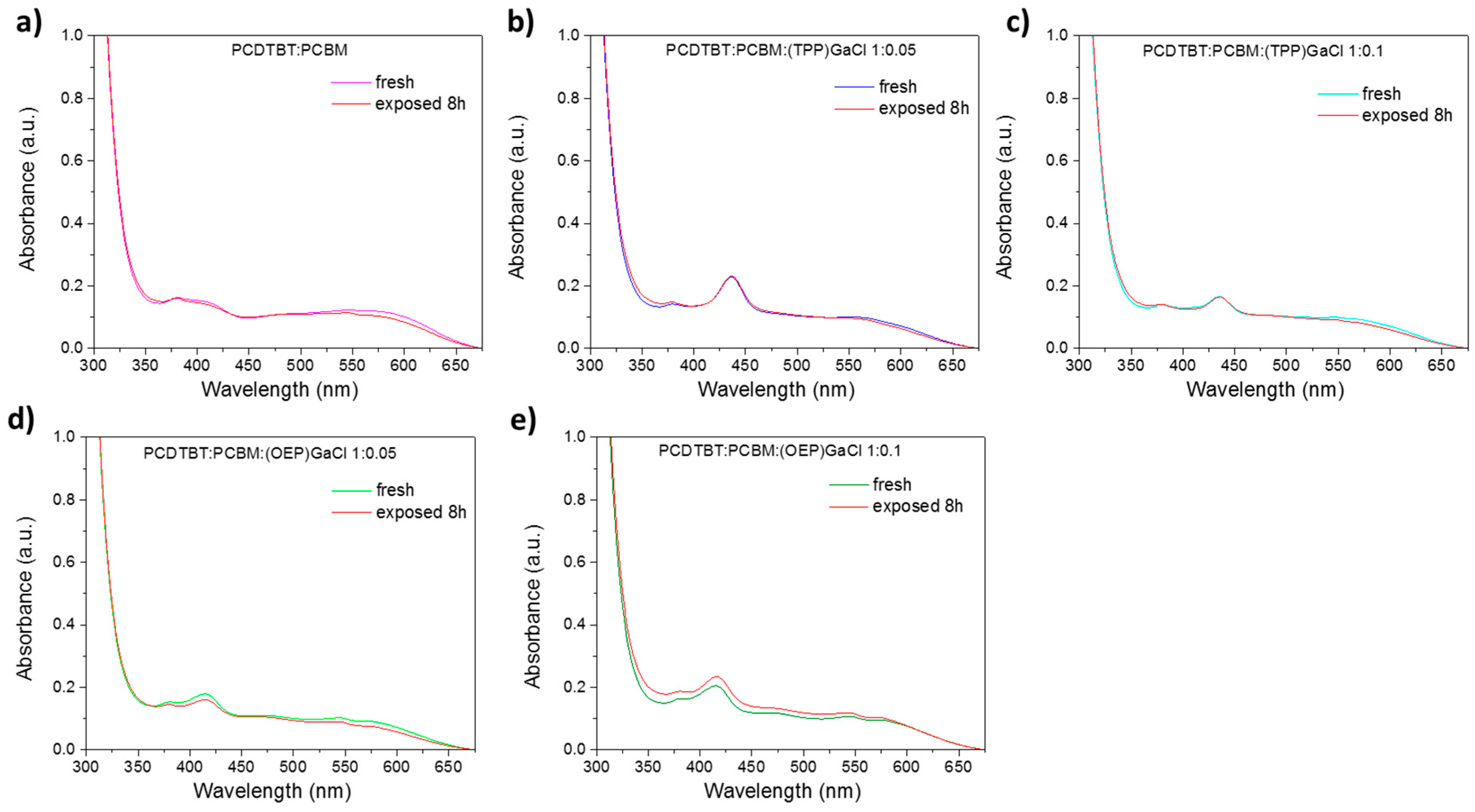
Another goal, except the optoelectronic, morphological, and structural investigation of GaCl porphrins-based ternary films, was the stability study of the prepared films under constant illumination conditions. Therefore, binary and ternary films were exposed to sunlight illumination in ambient conditions, and UV-Vis and FTIR spectroscopy, along with XRD measurements were performed. It is shown that the GaCl-porphyrins acknowledged that even in cases where the donor and acceptor materials demonstrate an ideal electronic relationship in a bulk heterojunction, it is essential for them to exhibit stability under typical environmental conditions to ensure an extended lifetime of the device. To assess the degree to which porphyrins contribute to the long-term stability of each photoactive film under ambient conditions, it was necessary to conduct an investigation of the samples when traces of oxygen or humidity were present. Figure 5 shows the UV-Vis absorption spectra of pristine PCDTBT:PCBM and porphyrin-modified blend films, where no differences before and after their exposure to 8 hours of sunlight illumination are noticed indicating no degradation of the binary and ternary films. On the other hand, in the case of P3HT:PCBM:GaCl (Figure S3) a blue shift of ~10 nm of the three main peaks of P3HT after exposure to sunlight illumination for 8 h. Note that the peak corresponding to the Soret band of the GaCl porphyrins remains unaffected.
Figure S4 and Figure S5 show the FTIR transmittance spectra of fresh and exposed to sunlight illumination for 8h of the P3HT:PCBM:GaCl and PCDTBT:PCBM:GaCl films, respectively. According to Figure S4a, the peak at 820 cm-1 of P3HT:PCBM photoactive film is slightly shifted to higher energies when the film exposed to sunlight illumination (8 h), suggesting a suppression of charge transfer from sulfur atoms of P3HT to PCBM. Moreover, P3HT:PCBM:(TPP)GaCl and P3HT:PCBM:(OEP)GaCl films remain stable upon sunlight illumination as no significant changes in the FTIR spectra are observed (Figure S4b-e). In the case of PCDTBT:PCBM-based binary and ternary films, FTIR analysis of all spectra (Figure S5a-e) reveals that there are no noticeable changes even after 8 hours of light exposure.
More interestingly, P3HT:PCBM:(TPP)GaCl film exhibited better structural stability upon porphyrin compared with the P3HT:PCBM film. Figure 6a and b shows the XRD patterns of fresh and exposed P3HT:PCBM and P3HT:PCBM:(TPP)GaCl films, respectively. In the case of binary film, the diffraction peak at 2θ=5.16o attributed to the (100) plane of P3HT is shifted to lower angle values (2θ=4.7o) resulting in increased d-spacing (from 1.71 nm to 1.88 nm) and reduced crystalline size of ~2.4 nm, and thus degradation of the exposed P3HT:PCBM film to sunlight illumination. On the other hand, P3HT:PCBM:(TPP)GaCl 1:0.05 is more resistant to sunlight, since small change in its crystallinity is observed. In particular, the d-spacing is slightly increased from 1.71 nm to 1.73 nm (estimated by Bragg law, where 2θ=5.1o), while the crystalline size reduced to ~5.5 nm (crystalline size of fresh film was 7.9 nm), indicating improved photostability.

2.3. Fabrication of ternary-based organic solar cells

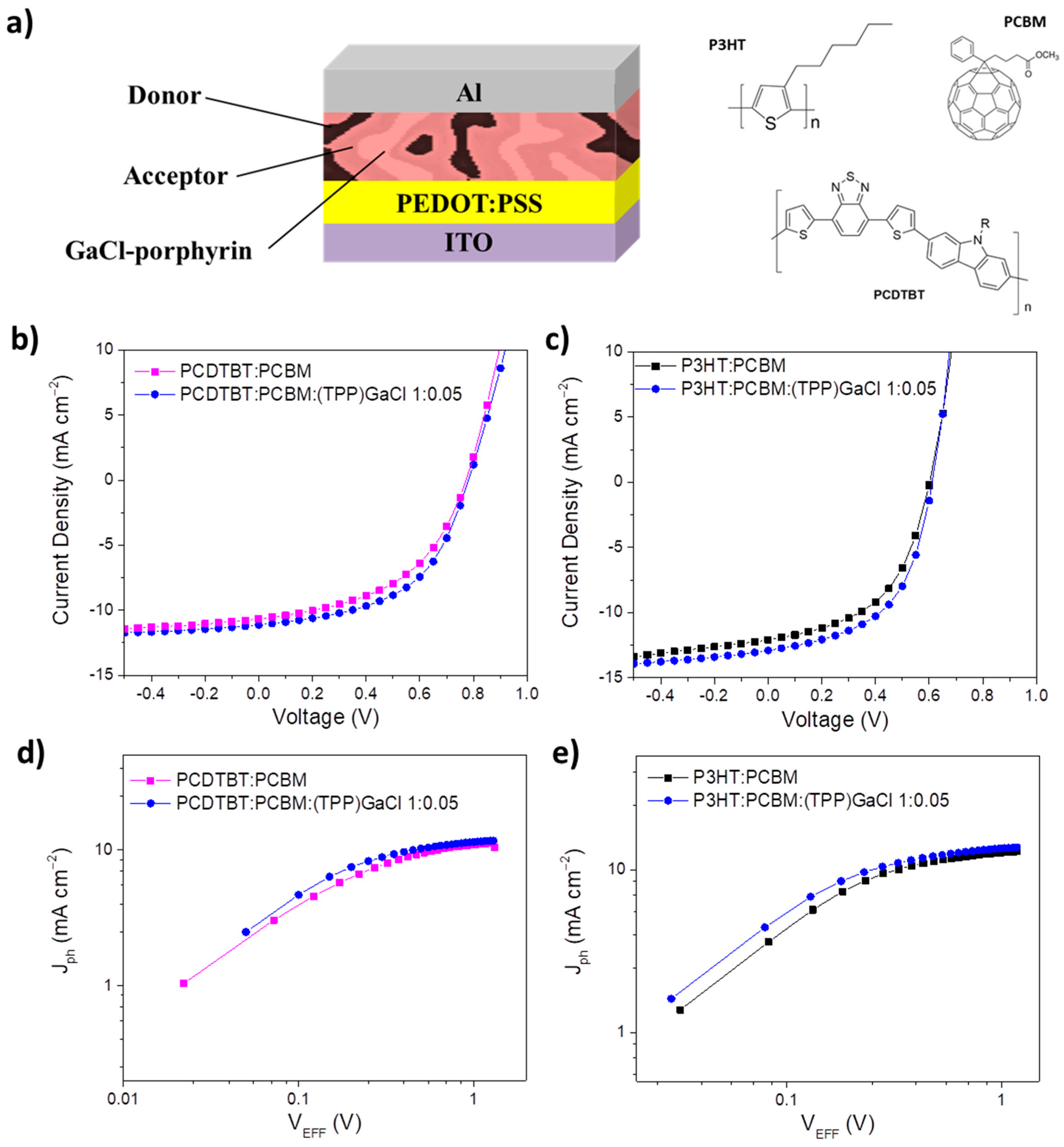
According to these results, organic solar cells (OSCs) with ternary photoactive layers based on (TPP)GaCl porphyrin of low concentration (1:0.05) were prepared. The device structure shown in Figure 7a along with the chemical structure of the polymer donors and fullerene acceptor constituted the active layer, was ITO/PEDOT:PSS/P3HT:PCBM:(TPP)GaCl 1:0.05/Al or ITO/PEDOT:PSS/PCDTBT:PCBM(TPP)GaCl 1:0.05/Al. Note that OSCs with binary photoactive layers (without the addition of the (TPP)GaCl porphyrin) were also fabricated for comparison reasons. Figure 7b and c depict the current density-voltage characteristic curves of binary and ternary OSCs based on the PCDTBT:PCBM and P3HT:PCBM blends, respectively. Enhanced device performance of about ~17 % is observed for the ternary devices with the (TPP)GaCl porphyrin as the third component of the active layer, compared to the binary OSCs. In particular, the device with the ternary PCDTBT:PCBM:(TPP)GaCl 1:0.05 active layer exhibited higher short-circuit current density (JSC) and fill factor (FF) values of 11.14 mA cm-2 and 0.53, respectively, and thus leading to higher power conversion efficiency (PCE) value of 4.61 %, compared with the corresponding binary (PCDTBT:PCBM) OSC with Jsc = 10.66 mA cm-2, FF = 0.48, and PCE = 3.94 % (Table 2). In the same context, improved Jsc of 12.90 mA cm-2, FF of 0.54, and PCE of 4.25 % are observed for the P3HT:PCBM:(TPP)GaCl 1:0.05 device, while the binary OSC without the porphyrin compound exhibited lower values (JSC = 12.09 mA cm-2, FF = 0.50, and PCE = 3.63 %). The JSC and FF enhancement suggests reduced recombination losses, when the (TPP)GaCl prophyrin with low concentration inserted in the active layer, which is also supported by the PL measurements (Figure 3e,f and Figure S1e,f), as well as, the higher shunt resistance (RSH) and the lower series resistance (RS) of the ternary OSCs compared with the binary devices summarized also in Table 2. Note that, an insignificant improvement on the VOC of the ternary devices is also observed assigned to the slight influence of the (TPP)GaCl 1:0.05 on the nanomorphology and crystallinity of the ternary films, as revealed from the AFM and XRD measurements. On the other hand, when the concentration of the (TPP)GaCl increased (1:0.01), lower performance of the ternary OSCs was obtained, as shown in Figure S6. Poor electrical parameters were also observed for the ternary devices based on the (OEP)GaCl porphyrin (Figure S6), which can be attributed to the rougher surface morphology and the suppressed crystallinity of the ternary active layers (Figure 4 and Figure S2).
In order to investigate the influence of (TPP)GaCl porphyrin on the charge generation efficiency, photocurrent density (JPH) versus effective voltage (VEFF) were plotted. Jph is estimated from JPH = JILL - JDARK, where JILL and JDARK are the current density values under illumination and in dark condition, respectively. VEFF is defined as VEFF = V0 – V, where V0 is the voltage at which the JPH is zero and V is the applied voltage. The estimated results of the binary and ternary OSCs based on PCDTBT:PCBM and P3HT:PCBM blends are shown in Figure 7d and e, respectively. It is observed that the ternary OSCs with the (TPP)GaCl porphyrin exhibit higher JPH values at low VEFF compared with the corresponding binary devices, suggesting improved exciton dissociation into free carriers. In addition, both ternary OSCs shows higher charge dissociation probabilities (P(E,T) – VEFF presented in Figure S7) and charge collection efficiency (estimated from JPH/JPH,SAT, where JPH,SAT is the saturated JPH) at short-circuit and at maximum power point, respectively, than the binary devices. Moreover, at high VEFF values (VEFF > 1), JPH,SAT of the ternary OSCs is higher than that of the binary ones, resulted in enhanced exciton generation rate (GMAX, estimated by the JPH,SAT = q GMAX L, where q is the elementary charge and L is the thickness of the photoactive layer).
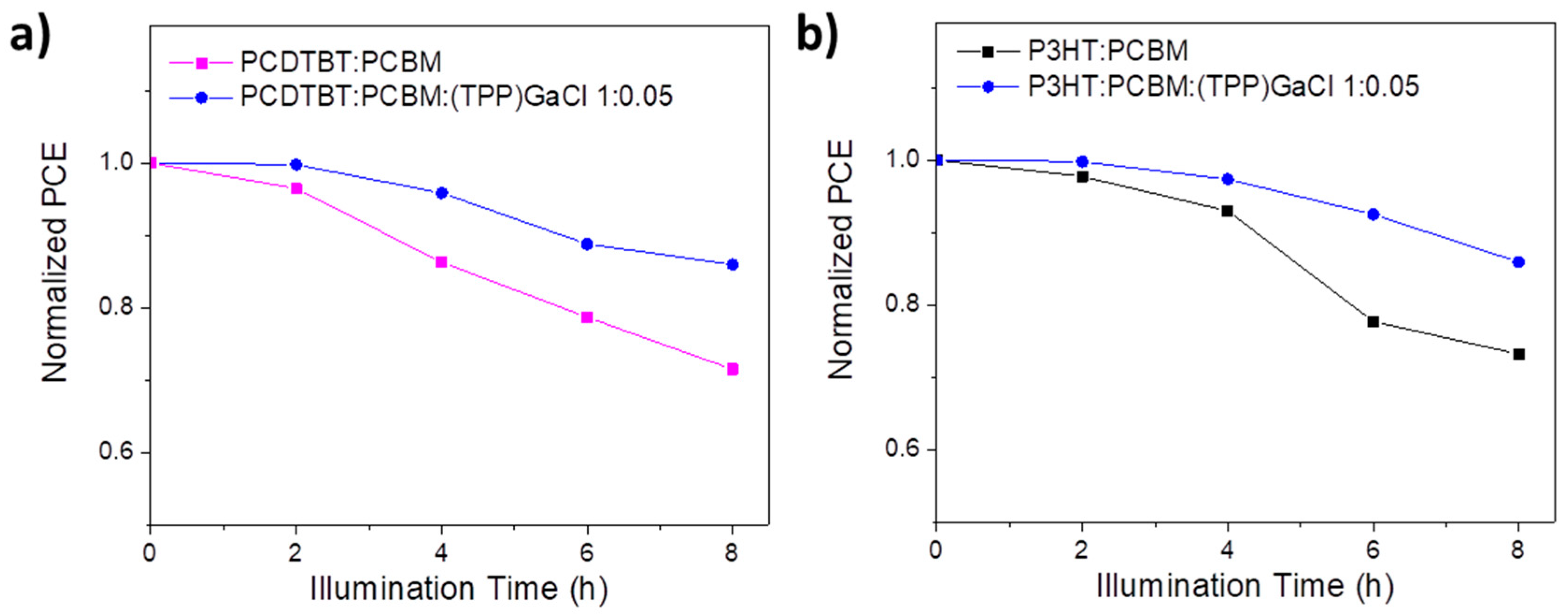
Except the device efficiency, the photostability of the (TPP)GaCl-based ternary OSCs was also investigated; expose the fabricated binary and ternary OSCs to sunlight illumination for 8 h without any encapsulation. Figure 8 shows the variation of normalized PCE values over a period of 8 h illumination for the binary and ternary OSCs. It is observed that PCDTBT:PCBM:(TPP)GaCl 1:0.05-based OSC retain over 85 % of its initial PCE value, while the efficiency of the binary device decreased to ~71 % after exposure to sunlight for 8 h (Figure 8a). Similar results also obtained for the ternary P3HT:PCBM-based OSC, where the P3HT:PCBM:(TPP)GaCl 1:0.05 device exhibited enhanced photostability (retain the ~86 % of its initial PCE value) compared with the exposed binary P3HT:PCBM OSC with its PCE to be decreased to ~73 % of its initial efficiency value (Figure 8b). This improved photostability can be attributed to the suppressed degradation, better nanomorphology and crystallinity of the ternary films after exposed to sunlight illumination for 8 h.

3. Conclusion

In conclusion, ternary air-processed photoactive layers consisting of a polymer donor (PCDTBT or P3HT) and a fullerene acceptor (PCBM) have been prepared using two GaCl-based porphyrins as the third component. Electrochemical measurements revealed a good energy level alignment between both gallium porphyrins, polymer donors (PCDTBT or P3HT) and PCBM-acceptor forming an efficient cascade system that could facilitate electron transfer between donor and acceptor. Therefore, ternary OSCs were fabricated. It was shown that the devices with the (TPP)GaCl 1:0.05 (i.e. PCDTBT:PCBM:(TPP)GaCl 1:0.05 or P3HT:PCBM:(TPP)GaCl 1:0.05) exhibited increased JSC and FF, and thus higher PCE compared the corresponding binary OSCs, assigned to the reduced recombination and improved exciton dissociation. On the other hand, the devices with (TPP)GaCl with higher concentration (1:0.1), as well as, the OSCs based on (OEP)GaCl exhibited low performance due to the significant alteration of the nanormophology of the ternary films with very rough surfaces and the suppressed crystalline formation. The devices with the (TPP)GaCl 1:0.05-ternary layer also exhibited enhanced photostability when the OSC exposed to sunlight illumination maintaining the ~85 % of the initial PCE value after 8 h, which is attributed to the better crystallinity and suppressed photodegradation of the ternary photoactive film.

4. Experimental Section

Film preparation. Binary P3HT:PCBM (1:0.8 wt% ratio) and PCDTBT:PCBM (1:4 wt% ratio) films were prepared by spin-coated the binary blended solutions from a 10 mg mL-1 in chloroform under air conditions. For the ternary films, 5 mg of each porphyrin molecule were dissolved in 1 mL of chloroform. Then binary:porphyrin 1:0.05 vv% ratio and 1:0.1 vv% ratio solutions were prepared forming the P3HT:PCBM:(TPP)GaCl, P3HT:PCBM:(OEP)GaCl, PCDTBT:PCBM:(TPP)GaCl, and PCDTBT:PCBM:(OEP)GaCl films through spin-coating. In particular, PCDTBT:PCBM-based binary and ternary films were formed through spin-coating at 1000 rpm for 2 min followed by thermal annealing at 60oC for 1 min. In the case of P3HT:PCBM and P3HT:PCBM:GaCl porphyrin, spin-coated was performed at 600 rpm for 40 s, and then the samples were place on a hot plate at 135 oC for 10 min. Note that all films were prepared under ambient conditions.
Thin film characterization methods. Fourier-transform infrared (FTIR) spectroscopy was performed using a Bruker Tensor 27 spectrometer equipped with a DTGS detector. Absorption spectra of the porphyrin, binary and ternary films were taken with a Perkin Elmer Lambda 40 UV-Vis spectrometer. Cyclic voltammetry of the two porphyrin molecules deposited on glass/ITO substrates were obtained with a VersaSTAT 4 potentiometer operated at a scan rate of 0.1 V s-1; the solvent was acetonitrile containing 0.1M LiClO4 as the electrolyte, while Ag/AgCl was the reference electrode. Steady-state photoluminescence (PL) spectra were recorded with a commercial platform (ARKEO—Cicci Research); the substrate was illuminated with a diode-pumped solid-state Nd:YVO4 + KTP laser (peak wavelength 532 nm ± 1 nm, optical power 1 mW on a circular spot of 2 mm of diameter: 31 mW cm−2) at an inclination of 45◦. The fluorescence on the opposite side of the substrate is focused on a bundle of fibers (10 mm in diameter) with an aspheric lens close to the substrate to maximize the PL. The bundle sends the signal to a CCD-based spectrometer. Integration time and the number of averaging was maintained the same to better compare the results. Time-resolved PL (TRPL) spectra were measured with an FS5 spectrofluorometer from Edinburgh Instruments using a 478.4 nm laser as an excitation source. The surface morphology of the binary P3HT:PCBM, PCDTBT:PCBM and ternary P3HT:PCBM:porphyrin and PCDTBT:PCBM:porphyrin films was investigated with atomic force microscopy (AFM) using an NT-MDT AFM system in tapping operation mode. X-ray diffactogramms (XRD) were recorded using a Siemens D500 diffractometer with Cu Kα radiation.
OSCs fabrication and characterization. Indium-tin oxide (ITO) coated on glass substrates were cleaned by sonication in deionized water, acetone, and isopropyl bath for 10 min each. Then, they subjected to UV-ozone for 20 min. Next, PEDOT:PSS (poly(3,4 - ethylenedioxythiophene)−poly(styrenesulfonate)) solution filtered with a 0.45 μm PVDF (polyvinylidene fluoride) filter was spin-coated on ITO at 4000 rpm for 45 s and the prepared films were placed on a hotplate at 150 oC for 30 min. air-processed PCDTBT:PCBM and P3HT:PCBM with and without the GaCl porphyrins were spin-coated on PEDOT:PSS to prepare the ternary and binary organic solar cells. The devices completed with the deposition of aluminum served as the cathode electrode. The current density–voltage (J–V) characteristic curves of the all, binary and ternary, OSCs were measured with a Keithley 2400 source-meter in the dark and under illumination with intensity of 100mW cm−2 using a Xe lamp as the illumination source equipped with a AM 1.5G filter in ambient conditions.

Supplementary Materials

Figure S1: UV-Vis absorption spectra of binary and ternary P3HT:PCBM films with porphyrin additives: (a) (TPP)GaCl and (b) (OEP)GaCl in various ratios. FTIR spectra of binary and ternary P3HT:PCBM films with porphyrin additives: (c) (TPP)GaCl and (d) (OEP)GaCl in various ratios. (e) Steady-state PL spectra of P3HT without or with (TPP)GaCl and (OEP)GaCl in various ratios and (f) Transient PL dynamics of the same samples; Figure S2: 5x5 μm2 AFM height images of (a) binary P3HT:PCBM, (b) P3HT:PCBM:(TPP)GaCl 1:0.05 (c) P3HT:PCBM:(TPP)GaCl 1:0.1, (d) P3HT:PCBM:(OEP)GaCl 1:0.05 and e) P3HT:PCBM:(OEP)GaCl 1:0.1 ternary blended films. (f) XRD patterns of the same samples; Figure S3: UV-Vis absorption spectra of fresh and exposed to sunlight illumination for 8 h of (a) binary P3HT:PCBM and ternary (b) P3HT:PCBM:(TTP)GaCl 1:0.05, (c) P3HT:PCBM:(TTP)GaCl 1:0.1, (d) P3HT:PCBM:(OEP)GaCl 1:0.05, and (d) P3HT:PCBM:(OEP)GaCl 1:0.1 films; Figure S4: FTIR spectra of fresh and exposed to sunlight illumination for 8 h of (a) binary P3HT:PCBM and ternary (b) P3HT:PCBM:(TTP)GaCl 1:0.05, (c) P3HT:PCBM:(TTP)GaCl 1:0.1, (d) P3HT:PCBM:(OEP)GaCl 1:0.05, and (d) P3HT:PCBM:(OEP)GaCl 1:0.1 films; Figure S5: FTIR spectra of fresh and exposed to sunlight illumination for 8 h of (a) binary PCDTBT:PCBM and ternary (b) PCDTBT:PCBM:(TTP)GaCl 1:0.05, (c) PCDTBT:PCBM:(TTP)GaCl 1:0.1, (d) PCDTBT:PCBM:(OEP)GaCl 1:0.05, and (e) PCDTBT:PCBM:(OEP)GaCl 1:0.1 films; Figure S6: J-V characteristic curves under 1.5 AM illumination of ternary OSCs based on (a) PCDTBT:PCBM and (b) P3HT:PCBM with (TPP)GaCl 1:0.1, (OEP)GaCl 1:0.05 and (OEP)GaCl 1:0.1; Figure S7: Exciton dissociation probability (P(E,T)) versus the effective voltage (VEFF) of binary and ternary OSCs based on (a) PCDTBT:PCBM and (b) P3HT:PCBM blends.

Author Contributions

Investigation, M.V, E.P, K.-K.A, and Z.G.; Writing-Original Draft, A.S., E.P.m and Z.G.; Methodology, L.C.P., I.K., V.K., and P.A.; Formal Analysis, A.C.; Data Curation, A.C.; Conceptualization, A.G.C.; Writing-Review and editing, A.S. and M.V.; Supervision, M.V. and P.A.; Project Administration, M.V.; Visualization, A.S., M.V., and A.G.C.

Acknowledgments

This work was supported by the research project “HΕLIOKERAMOS” - MIS 5066858, funded by the Operational Programme (EPAnEK) "Competitiveness, Entrepreneurship and Innovation" (NSRF 2014-2020), under the special action "Industrial Materials" and co-financed by Greece and the European Union (European Regional Development Fund). This research was also supported by Grant 81365 from the Research Committee of the University of Patras via “C. CARATHEODORI” program.

References

  1. Yan, C.; Barlow, S.; Wang, Z.; Yan, H.; Jen, A.K.Y.; Marder, S.R.; Zhan, X. Non-fullerene acceptors for organic solar cells. Nat. Rev. Mater. 2018, 3, 18003. [Google Scholar] [CrossRef]
  2. Bergqvist, J.; Österberg, T.; Melianas, A.; Aguirre, L.E.; Tang, Z.; Cai, W.; Ma, Z.; Kemerink, M.; Gedefaw, D.; Andersson, M.R.; Inganäs, O. Asymmetric photocurrent extraction in semitransparent laminated flexible organic solar cells. NPJ Flexible Electron. 2018, 2, 4. [Google Scholar] [CrossRef]
  3. Wadsworth, A.; Moser, M.; Marks, A.; Little, M.S.; Gasparini, N.; Brabec, C.J.; Baran, D.; McCulloch, I. Critical review of the molecular design progress in non-fullerene electron acceptors towards commercially viable organic solar cells. Chem. Soc. Rev. 2019, 48, 1596. [Google Scholar] [CrossRef]
  4. Duan, L.; Elumalai, N.K.; Zhang, Y.; Uddin, A. Progress in Stability of Organic Solar CellsSol. Energy Mater. Sol. Cells 2019, 193, 22. [Google Scholar] [CrossRef]
  5. Duan, L.; Yi, H.; Wang, Z.; Zhang, Y.; Haque, F.; Sang, B.; Deng, R.; Uddin, A. Semitransparent organic solar cells based on PffBT4T-2OD with a thick active layer and near neutral colour perception for window applications. Sustainable Energy Fuels 2019, 3, 2456. [Google Scholar] [CrossRef]
  6. Sadasivuni, K.K.; Deshmukh, K.; Ahipa, T.N.; Muzaffar, A.; Ahamed, M.B.; Pasha, S.K.K.; Al-Maadeed, M.A.-A. Flexible, biodegradable and recyclable solar cells: a review. J. Mater. Sci.: Mater. Electron. 2019, 30, 951. [Google Scholar] [CrossRef]
  7. Wang, D.; Liu, J.; Li, Y.; Zhou, G.; Zhan, L.; Zhu, H.; Lu, X.; Chen, H.; Li, C.-Z. High-performance and eco-friendly semitransparent organic solar cells for greenhouse applications. Joule 2021, 5, 945. [Google Scholar] [CrossRef]
  8. Li, Y.; Lin, J.D.; Che, X.; Qu, Y.; Liu, F.; Liao, L.-S.; Forrest, S.R. High efficiency near-infrared and semitransparent non-fullerene acceptor organic photovoltaic cells. J. Am. Chem. Soc. 2017, 139, 17114. [Google Scholar] [CrossRef]
  9. Ravishankar, E.; Booth, R.E.; Saravitz, C.; Sederoff, H.; Ade, H.W.; O’Connor, B.T. Achieving net zero energy greenhouses by integrating semitransparent organic solar cells. Joule 2020, 4, 490. [Google Scholar] [CrossRef]
  10. Xie, L.; Song, W.; Ge, J.; Tang, B.; Zhang, X.; Wu, T.; Ge, Z. Recent progress of organic photovoltaics for indoor energy harvesting. Nano Energy 2021, 82, 105770. [Google Scholar] [CrossRef]
  11. Su, Y.-J.; Huang, S.-C.; Chen, t.-W.; Chueh, L.-C.; Cui, Y.; Hong, L.; Yao, H.; Hou, J.; Chen, J.-T.; Hsu, C.-S. Elucidating End-Group Modifications of Carbazole-Based Nonfullerene Acceptors in Indoor Applications for Achieving a PCE of over 20%. ACS Appl. Mater. Interfaces 2021, 13, 26247. [Google Scholar] [CrossRef]
  12. Cui, Y.; Hong, L.; Hou, J. Organic Photovoltaic Cells for Indoor Applications: Opportunities and Challenges. ACS Appl. Mater. Interfaces 2020, 12, 38815. [Google Scholar] [CrossRef] [PubMed]
  13. Ryu, H.S.; Park, S.Y.; Lee, T.H.; Kim, J.Y.; Woo, H.Y. Recent progress in indoor organic photovoltaics. Nanoscale 2020, 12, 5792. [Google Scholar] [CrossRef] [PubMed]
  14. Jung, S.; Oh, J.; Yang, U.J.; Lee, S.M.; Lee, J.; Jeong, M.; Cho, Y.; Kim, S.; Baik, J.M.; Yang, C. 3D Cu ball-based hybrid triboelectric nanogenerator with non-fullerene organic photovoltaic cells for self-powering indoor electronics. Nano Energy 2020, 77, 105271. [Google Scholar] [CrossRef]
  15. Jia, Z.; Chen, Z.; Chen, X.; Yao, J.; Yan, B.; Sheng, R.; Zhu, H.; Yang, Y.M. 19.34 cm2 large-area quaternary organic photovoltaic module with 12.36% certified efficiency. Photonics Res. 2021, 9, 324. [Google Scholar] [CrossRef]
  16. Qin, F.; Sun, L.; Chen, H.; Liu, Y.; Lu, X.; Wang, W.; Liu, T.; Dong, X.; Jiang, P.; Jiang, Y.; Wang, L.; Zhou, Y. 54 cm2 Large-Area Flexible Organic Solar Modules with Efficiency Above 13%. Adv. Mater. 2021, 2103017. [Google Scholar] [CrossRef]
  17. Dong, X.; Jiang, Y.; Sun, L.; Qin, F.; Zhou, X.; Lu, X.; Wang, W.; Zhou, Y. Large-Area Organic Solar Modules with Efficiency Over 14%. Adv. Funct. Mater. 2021, 32, 2110209. [Google Scholar] [CrossRef]
  18. Yang, F.; Huang, Y.; Li, Y.; Li, Y. Large-area flexible organic solar cells. npj Flexible Electronics 2021, 5, 30. [Google Scholar] [CrossRef]
  19. Kini, G.P.; Jeon, S.J; Moon, D.K. Latest progress on photoabsorbent materials for multifunctional semitransparent organic solar cells. Adv. Funct. Mater. 2021, 31, 2007931. [Google Scholar] [CrossRef]
  20. Brus, V.V.; Lee, J.; Luginbuhl, B.R.; Ko, S.J.; Bazan, G.C.; Nguyen, T.Q. Solution-processed semitransparent organic photovoltaics: from molecular design to device performance. Adv. Mater. 2019, 31, 1900904. [Google Scholar] [CrossRef]
  21. Chen, W.; Zhang, J.; Xu, G.; Xue, R.; Li, Y.; Zhou, Y.; Hou, J.; Li, Y. A semitransparent inorganic perovskite film for overcoming ultraviolet light instability of organic solar cells and achieving 14.03% efficiency. Adv. Mater. 2018, 30, 1800855. [Google Scholar] [CrossRef] [PubMed]
  22. Krebs, F.C. Fabrication and processing of polymer solar cells: A review of printing and coating techniques. Sol. Energy Mater. Sol. Cells 2009, 93, 394. [Google Scholar] [CrossRef]
  23. Xue, P.; Cheng, P.; Han, R.P.S.; Zhan, X. Printing fabrication of large-area non-fullerene organic solar cells. Mater. Horiz. 2022, 9, 194. [Google Scholar] [CrossRef]
  24. Wang, G.; Adil, M.A; Zhang, J.; We, Z. Large-Area Organic Solar Cells: Material Requirements, Modular Designs, and Printing Methods. Adv. Mater. 2019, 31, 1805089. [Google Scholar] [CrossRef]
  25. Ghosh, A.; Bhandari, S.; Sundaram, S.; Mallick, T.K. Carbon counter electrode mesoscopic ambient processed & characterised perovskite for adaptive BIPV fenestration. Renew. Energy 2020, 145, 2151. [Google Scholar] [CrossRef]
  26. Cannavale, A.; Ierardi, L.; Hörantner, M.; Eperon, G.E.; Snaith, H.J.; Ayr, U.; Martellotta, F. Improving energy and visual performance in offices using building integrated perovskite-based solar cells: A case study in Southern Italy. Appl. Energy 2017, 205, 834. [Google Scholar] [CrossRef]
  27. Cannavale, A.; Hörantner, M.; Eperon, G.E.; Snaith, H.J.; Fiorito, F.; Ayr, U.; Martellotta, F. Building integration of semitransparent perovskite-based solar cells: Energy performance and visual comfort assessment. Appl. Energy 2017, 194, 94–107. [Google Scholar] [CrossRef]
  28. Xu, J.; Chen, Y.; Dai, L. Efficiently photo-charging lithium-ion battery by perovskite solar cell. Nat. Commun. 2015, 6, 8103. [Google Scholar] [CrossRef]
  29. Kaltenbrunner, M.; White, M.S.; Głowacki, E.D.; Sekitani, T.; Someya, T.; Sariciftci, N.S.; Bauer, S. Ultrathin and lightweight organic solar cells with high flexibility. Nat. Commun. 2012, 3, 770. [Google Scholar] [CrossRef]
  30. Güler, E.N.; Distler, A.; Basu, R.; Brabec, C.J.; Egelhaaf, E.-J. Fully solution-processed, light-weight, and ultraflexible organic solar cells. Flex. Print. Electron. 2022, 7, 025003. [Google Scholar] [CrossRef]
  31. Chen, X.; Xu, G.; Zeng, G.; Gu, H.; Chen, H.; Xu, H.; Yao, H.; Li, Y.; Hou, J.; Li, Y. Realizing ultrahigh mechanical flexibility and >15% efficiency of flexible organic solar cells via a “welding” flexible transparent electrode. Adv. Mater. 2020, 32, 1908478. [Google Scholar] [CrossRef] [PubMed]
  32. Li, S.; Li, Z.; Wan, X.; Chen, Y. Recent progress in flexible organic solar cells. eScience 2022. [Google Scholar] [CrossRef]
  33. Li, X.; Xia, R.; Yan, K.; Ren, J.; Yip, H.-L.; Li, C.-Z.; Chen, H. Semitransparent organic solar cells with vivid colors. ACS Energy Lett. 2020, 5, 3115. [Google Scholar] [CrossRef]
  34. Jeong, E.G.; Jeon, Y.; Cho, S.H.; Choi, K.C. Textile-based washable polymer solar cells for optoelectronic modules: toward self-powered smart clothing. Energy Environ. Sci. 2019, 12, 1878. [Google Scholar] [CrossRef]
  35. Hashemi, S.A.; Ramakrishna, S.; Aberle, A.G. Recent progress in flexible–wearable solar cells for self-powered electronic devices. Energy Environ. Sci. 2020, 13, 685. [Google Scholar] [CrossRef]
  36. Lv, D.; Jiang, Q.; Shang, Y. Highly efficient fiber-shaped organic solar cells toward wearable flexible electronics. npj Flex Electron 2022, 6, 38. [Google Scholar] [CrossRef]
  37. Nicolaidis, N.C.; Hollott, P.V.; Stanwell, B.; Gill, I.A.; Bull, J.E.; Bentsen, S.; Iredale, J.; Pappenfus, T.M.; Dastoor, P.C.; Feron, K.; Griffith, M.J.; Holmes, N.P. Developing a Portable Organic Solar Cell Kit Suitable for Students to Fabricate and Test Solar Cells in the Laboratory. J. Chem. Educ. 2020, 97, 3751. [Google Scholar] [CrossRef]
  38. Jahandar, M.; Kim, S.; Lim, D.C. Indoor organic photovoltaics for self-sustaining IoT devices: progress, challenges and practicalization. ChemSusChem 2021, 14, 1–27. [Google Scholar] [CrossRef]
  39. Hwang, S.; Yasuda, T. Indoor photovoltaic energy harvesting based on semiconducting π-conjugated polymers and oligomeric materials toward future IoT applications, Polym. J. 2022. [Google Scholar] [CrossRef]
  40. Arai, R.; Furukawa, S.; Hidaka, Y.; Komiyama, H.; Yasuda, T. High-performance organic energy-harvesting devices and modules for self-sustainable power generation under ambient indoor lighting environments. ACS Appl Mater Interfaces 2019, 11, 9259. [Google Scholar] [CrossRef]
  41. Luke, J.; Corrêa, L.; Rodrigues, J.; Martins, J.; Daboczi, M.; Bagnis, D.; Kim, J.-S. A Commercial Benchmark: Light-Soaking Free, Fully Scalable, Large-Area Organic Solar Cells for Low-Light Applications. Adv. Energy Mater. 2021, 11, 2003405. [Google Scholar] [CrossRef]
  42. Chen, B.; Baek, S.-W.; Hou, Y.; Aydin, E.; De Bastiani, M.; Scheffel, B.; Proppe, A.; Huang, Z.; Wei, M.; Wang, Y.-K.; Jung, E.-H. , Allen, T.G.; Van Kerschaver, E.; de Arquer, F.P.G.; Saidaminov, M.I.; Hoogland, S.; De Wolf, S.; Sargent, E.H. Enhanced optical path and electron diffusion length enable high-efficiency perovskite tandems. Nat. Commun. 2020, 11, 1257. [Google Scholar] [CrossRef] [PubMed]
  43. Lee, H.K.H.; Wu, J.; Barbé, J.; Jain, S.M.; Wood, S.; Speller, E.M.; Li, Z.; Castro, F.A.; Durrant, J.R.; Tsoi, W.C. Organic photovoltaic cells-promising indoor light harvesters for self-sustainable electronics. J. Mater. Chem. A 2018, 6, 5618. [Google Scholar] [CrossRef]
  44. Burlingame, Q.; Song, B.; Ciammaruchi, L.; Zanotti, G.; Hankett, J.; Chen, Z.; Katz, E.A.; Forrest, S.R. Reliability of Small Molecule Organic Photovoltaics with Electron-Filtering Compound Buffer Layers. Adv. Energy Mater. 2016, 6, 1601094. [Google Scholar] [CrossRef]
  45. Peters, C.H.; Sachs-Quintana, I.-T.; Kastrop, J.P.; Beaupré, S.; Leclerc, M.; McGehee, M.D. High efficiency polymer solar cells with long operating lifetimes. Adv. Energy Mater. 2011, 1, 491. [Google Scholar] [CrossRef]
  46. Du, X.; Heumueller, T.; Gruber, W.; Classen, A.; Unruh, T.; Li, N.; Brabec, C.J. Efficient Polymer Solar Cells Based on Non-fullerene Acceptors with Potential Device Lifetime Approaching 10 Years. Joule 2019, 3, 215. [Google Scholar] [CrossRef]
  47. Burlingame, Q.; Huang, X.; Liu, X.; Forrest, S.R. Intrinsically stable organic solar cells under high-intensity illumination. Nature 2019, 573, 394. [Google Scholar] [CrossRef]
  48. Kawano, K.; Pacios, R.; Poplavskyy, D.; Nelson, J.; Bradley, D.D.C.; Durrant, J.R. Degradation of organic solar cells due to air exposure. Sol. Energy Mater. Sol. Cells 2006, 20, 3520. [Google Scholar] [CrossRef]
  49. Wang, X.; Zhao, C.X.; Xu, G.; Chen, Z.-K.; Zhu, F. Degradation mechanisms in organic solar cells: Localized moisture encroachment and cathode reaction. Sol Energy Sol. Cells 2012, 104, 1–4. [Google Scholar] [CrossRef]
  50. Ye, L.; Hu, H.; Ghasemi, M.; Wang, T.; Collins, B.A.; Kim, J.-H.; Jiang, K.; Carpenter, J.H.; Li, H.; Li, Z.; McAfee, T.; Zhao, J.; Chen, X.; Lai, J.L.Y.; Ma, T.; Bredas, J.-L.; Yan, H.; Ade, H. Quantitative relations between interaction parameter, miscibility and function in organic solar cells. Nat. Mater. 2018, 17, 253–260. [Google Scholar] [CrossRef]
  51. Jørgensen, M.; Norrman, K.; Krebs, F.C. Stability/degradation of polymer solar cells. Sol. Energy Mat. Sol. Cells 2008, 92, 686. [Google Scholar] [CrossRef]
  52. Pacios, R.; Chatten, A.J.; Kawano, K.; Durrant, J.R.; Bradley, D.D.C.; Nelson, J. Effects of Photo-oxidation on the Performance of Poly[2-methoxy-5-(3′,7′-dimethyloctyloxy)-1,4-phenylene vinylene]:[6,6]-Phenyl C61-Butyric Acid Methyl Ester Solar Cells. Adv. Funct. Mater. 2006, 16, 2117. [Google Scholar] [CrossRef]
  53. Howard, I.A.; Mauer, R.; Meister, M.; Laquai, F. Effect of Morphology on Ultrafast Free Carrier Generation in Polythiophene:Fullerene Organic Solar Cells. J. Am. Chem. Soc. 2010, 132, 14866. [Google Scholar] [CrossRef] [PubMed]
  54. Xiao, Z.; Yuan, Y.; Yang, B.; VanDerslice, J.; Chen, J.; Dyck, O.; Duscher, G.; Huang, J. Universal formation of compositionally graded bulk heterojunction for efficiency enhancement in organic photovoltaics. Adv. Mater. 2014, 26, 3068. [Google Scholar] [CrossRef] [PubMed]
  55. Meng, B.; Wang, Z.; Ma, W.; Xie, Z.; Liu, J.; Wang, L. A Cross-Linkable Donor Polymer as the Underlying Layer to Tune the Active Layer Morphology of Polymer Solar Cells. Adv. Funct. Mater. 2016, 26, 226. [Google Scholar] [CrossRef]
  56. He, Z.; Xiao, B.; Liu, F.; Wu, H.; Yang, Y.; Xiao, S.; Wang, C.; Russell, T.P.; Cao, Y. Single-junction polymer solar cells with high efficiency and photovoltage. Nat. Photon. 2015, 9, 174. [Google Scholar] [CrossRef]
  57. He, Z.; Zhong, C.; Su, S.; Xu, M.; Wu, H.; Cao, Y. Enhanced power-conversion efficiency in polymer solar cells using an inverted device structure. Nat. Photon. 2012, 6, 591. [Google Scholar] [CrossRef]
  58. Lee, C.-Y.; Tsao, C.-S.; Lin, H.-K.; Cha, H.-C.; Chung, T.-Y.; Sung, Y.-M.; Huang, Y.-C. Encapsulation improvement and stability of ambient roll-to-roll slot-die-coated organic photovoltaic modules. Sol. Energy 2021, 213, 136. [Google Scholar] [CrossRef]
  59. Chen, J.; Yu, X.; Hong, K.; Messman, J.M.; Pickel, D.L.; Xiao, K.; Dadmun, M.D.; Mays, J.W.; Rondinone, A.J.; Sumpterand, B.G.; Kilbey II, S.M. , Ternary Behavior and Systematic Nanoscale Manipulation of Domain Structures in P3HT/PCBM/P3HT-b-PEO Films. J. Mater. Chem. 2012, 22, 13013. [Google Scholar] [CrossRef]
  60. Chen, H.P.; Chen, J.H.; Yin, W.; Yu, X.; Shao, M.; Xiao, K.; Hong, K.L.; Pickel, D.L.; Kochemba, W.M.; Kilbey II, S.M.; Dadmun, M. Correlation of Polymeric Compatibilizer Structure to its Impact on the Morphology and Function of P3HT:PCBM Bulk Heterojunctions. J. Mater. Chem. A 2013, 1, 5309. [Google Scholar] [CrossRef]
  61. Cheng, P.; Zhan, X. Versatile Third Components for Efficient and Stable Organic Solar Cells. Mater. Horiz. 2015, 2, 462. [Google Scholar] [CrossRef]
  62. An, Q.; Zhang, F.; Zhang, J.; Tang, W.; Deng, Z.; Hu, B. Versatile Ternary Organic Solar Cells: A Critical Review. Energy Environ. Sci. 2016, 9, 281. [Google Scholar] [CrossRef]
  63. Balis, N.; Verykios, A.; Soultati, A.; Constantoudis, V.; Papadakis, M.; Kournoutas, F.; Drivas, C.; Skoulikidou, M.-C.; Gardelis, S.; Fakis, M.; Kennou, S.; Kontos, A.G.; Coutsolelos, A.G.; Falaras, P.; Vasilopoulou, M. Triazine-substituted zinc porphyrin as an electron transport interfacial material for efficiency enhancement and degradation retardation in planar perovskite solar cells. ACS Appl. Energy Mater. 2018, 1, 3216. [Google Scholar] [CrossRef]
  64. Tountas, M.; Verykios, A.; Polydorou, E.; Kaltzoglou, A.; Soultati, A.; Balis, N.; Angaridis, P.A.; Papadakis, M.; Nikolaou, V.; Auras, F.; Palilis, L.C.; Tsikritzis, D.; Evangelou, E.K.; Gardelis, S.; Koutsoureli, M.; Papaioannou, G.; Petsalakis, I.D.; Kennou, S.; Davazoglou, D.; Argitis, P.; Falaras, P.; Coutsolelos, A.G.; Vasilopoulou, M. Engineering of porphyrin molecules for use as effective cathode interfacial modifiers in organic solar cells of enhanced efficiency and stability, ACS Appl. Mater. Interfaces. 2018, 10, 20728. [Google Scholar] [CrossRef]
  65. Piradi, V.; Xu, X.; Wang, Z.; Ali, J.; Peng, Q.; Liu, F.; Zhu, X. Panchromatic ternary organic solar cells with porphyrin dimer and absorption-complementary benzodithiophene-based small molecules. ACS Appl. Mater. Interfaces 2019, 11, 6283–6291. [Google Scholar] [CrossRef] [PubMed]
  66. Kadish, K.M.; Boisselier-Cocolios, B.; Coutsolelos, A.; Mitaine, P.; Guilard, R. Electrochemistry and Spectroelectrochemistry of Gallium(III) Porphyrins. Redox properties of Five-Coordinate Ionic and Sigma-Bonded Complexes. Inorg. Chem 1985, 24, 4521–4528. [Google Scholar] [CrossRef]
  67. Coutsolelos, A.; Guilard, R. Synthese et caracteristiques physicochimiques de gallioporphyrines a laison σ metal carbone. J. Organometallic Chem. 1983, 253, 273–282. [Google Scholar] [CrossRef]
  68. Coutsoleleos, A.; Guilard, R.; Bayeul, D.; Lecomte, C. Gallium (III) porphyrins: synthesis and physicochemical characteristics of halogeno gallium (III) porphyrins-X-ray crystal structure of chloro-(5,10,15,20-tetraphenylporphyrinato) gallium (III). Polyhedron 1986, 5, 1157–1164. [Google Scholar] [CrossRef]
  69. Bieniasz, L.K. Cyclic Voltammetric Current Functions Determined with a Prescribed Accuracy by the Adaptive Huber Method for Abel Integral Equations. Anal. Chem. 2008, 80, 9659–9665. [Google Scholar] [CrossRef]
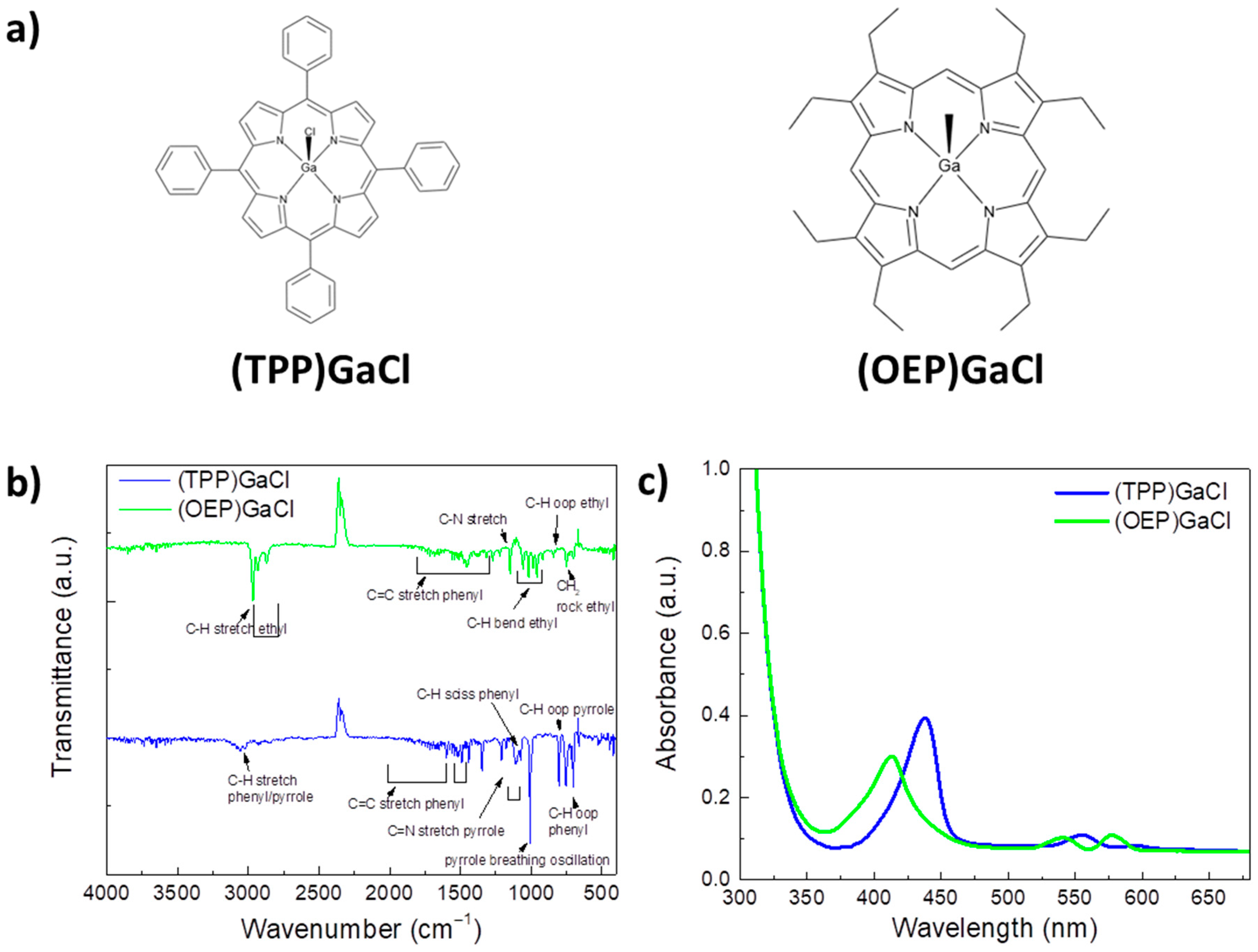
Figure 1. (a) Molecular structure of (TPP)GaCl and (OEP)GaCl porphyrins. (b) FTIR transmittance and (c) UV-Vis absorption spectra of the corresponding porphyrin thin films.
Preprints 81612 g001
Figure 2. Cyclic voltammograms of (a), (b) (TPP)GaCl and (c), (d) (OEP)GaCl porphyrins. (a) and (c) refers to the oxidation processes, while (b) and (d) to the reduction processes. (e) Schematic energy level diagram of the organic semiconductors and gallium-porphyrin compounds illustrating the functionalization of porphyrins as electron cascade.
Preprints 81612 g002
Figure 3. UV-Vis absorption spectra of binary and ternary PCDTBT:PCBM films with porphyrin additives: (a) (TPP)GaCl and (b) (OEP)GaCl in various ratios. FTIR spectra of binary and ternary PCDTBT:PCBM films with porphyrin additives: (c) (TPP)GaCl and (d) (OEP)GaCl in various ratios. (e) Steady-state PL spectra of PCDTBT without or with (TPP)GaCl and (OEP)GaCl in various ratios and (f) transient PL dynamics of the same samples.
Preprints 81612 g003
Figure 4. 5x5 μm2 AFM height images of (a) binary PCDTBT:PCBM, (b) PCDTBT:PCBM:(TPP)GaCl 1:0.05 (c) PCDTBT:PCBM:(TPP)GaCl 1:0.1, (d) PCDTBT:PCBM:(OEP)GaCl 1:0.05 and e) PCDTBT:PCBM:(OEP)GaCl 1:0.1 ternary blended films. (f) XRD patterns of the same samples.
Preprints 81612 g004
Figure 5. UV-Vis absorption spectra of fresh and exposed to sunlight illumination for 8 h of (a) binary PCDTBT:PCBM and ternary (b) PCDTBT:PCBM:(TTP)GaCl 1:0.05, (c) PCDTBT:PCBM:(TTP)GaCl 1:0.1, (d) PCDTBT:PCBM:(OEP)GaCl 1:0.05, and (d) PCDTBT:PCBM:(OEP)GaCl 1:0.1 films.
Preprints 81612 g005
Figure 6. XRD patterns of fresh and exposed to sunlight illumination for 8 h of (a) binary P3HT:PCBM and ternary (b) P3HT:PCBM:(TPP)GaCl 1:0.05 films.
Preprints 81612 g006
Figure 7. (a) Device structure and chemical structure of the donor and acceptor organic materials used in the photoactive layer of the ternary OSCs. J-V characteristic curves under 1.5 AM illumination of ternary OSCs based on (b) PCDTBT:PCBM:(TPP)GaCl 1:0.05 and (c) P3HT:PCBM:(TPP)GaCl 1:0.05 layers. J-V curves of binary devices are also depicted. (d) and (e) Variation of photocurrent density (Jph) with effective voltage (Veff) of the same devices.
Preprints 81612 g007
Figure 8. Stability study of binary and ternary OSCs. Normalized PCE values versus illumination time of OSCs based on (a) PCDTBT:PCBM:(TPP)GaCl 1:0.05 and (b) P3HT:PCBM:(TPP)GaCl 1:0.05 layers, compared with the corresponding binary devices. .
Preprints 81612 g008
Table 1. Cyclic voltammetry calculated data of porphyrins.
Porphyrin Eox (eV) Ered (eV) EHOMO ELUMO
(TTP)GaCl 0.5 -1.1 -4.9 -3.3
(OEP)GaCl 0.4 -1.2 -4.8 -3.2
Table 2. Electrical parameters of the fabricated OSCs estimated by the J-V characteristic curves shown in Figure 7(b) and (c).
Active layer JSC(mA cm-2) VOC (V) FF PCE (%) RS
(Ω cm2)
RSH
(Ω cm2)
PCDTBT:PCBM -10.66 0.77 0.48 3.94 11.5 401
PCDTBT:PCBM:(TTP)GaCl 1:0.05 -11.14 0.78 0.53 4.61 8.2 489
P3HT:PCBM -12.09 0.60 0.50 3.63 5.3 289
P3HT:PCBM:(TTP)GaCl 1:0.05 -12.90 0.61 0.54 4.25 3.7 318
Disclaimer/Publisher’s Note: The statements, opinions and data contained in all publications are solely those of the individual author(s) and contributor(s) and not of MDPI and/or the editor(s). MDPI and/or the editor(s) disclaim responsibility for any injury to people or property resulting from any ideas, methods, instructions or products referred to in the content.
Copyright: This open access article is published under a Creative Commons CC BY 4.0 license, which permit the free download, distribution, and reuse, provided that the author and preprint are cited in any reuse.
Prerpints.org logo

Preprints.org is a free preprint server supported by MDPI in Basel, Switzerland.

Subscribe

© 2024 MDPI (Basel, Switzerland) unless otherwise stated