We will solve Laplace’s equation
with various boundary conditions to determine the electric potentials (and thereby, the electric fields) produced by various charge distributions and conductors and dielectrics [
18]. Since the boundary conditions and charge distributions we will consider will typically have some sort of spherical symmetry, it will be easier to solve Laplace’s equation in the
spherical polar coordinates rather than Cartesian coordinates. To facilitate the solution, we first state the following lemma on the form of the Laplace operator in spherical polar coordinates.
For completeness, we provide the proof of Lemma 1 in the Appendix.
We now establish the solution of Laplace’s equation in spherical coordinates with spherical boundary conditions.
In order to prove Proposition 1, we need 2 additional lemmas, whose proofs are omitted.
Proof (Proof of Proposition 1). To solve Laplace’s equation with the stated boundary conditions [
22], we will use the so-called
separation of variables method [
23]. We note that the setting of Proposition 1 is similar to that of Lemma 2, except that the functions
and
are now functions of
only; therefore, by Lemma 2, if we can find a solution
matching the boundary conditions, then that would be the unique solution, at most up to an additive constant. To this end, let us define a
trial solution of Laplace’s equation of the form
where
and
are twice differentiable functions. Using (
2), the Laplace equation then reduces to
or
Now, Equation (
6) has to hold for every
in the domain, therefore, we must have
where
K is a constant independent of the coordinates
Examining the
equation first, we obtain, through a slight rearrangement,
Writing
enables us to write
and the equation therefore reduces to
Now, dividing throughout by
writing
and noting that
the
equation becomes, in terms of
as the independent variable,
Equation (
7) is the Legendre equation [
19] with
For non-integer
the solutions to Legendre’s equation are power series with radius of convergenece smaller than
For the current problem, however, the domain is
Therefore, the only possible solutions to (
7) that would make the trial solution valid, should be polynomials. Through the application of Sturm–Liouville theory (see, for example, [
21]), we can conclude that the solutions are indeed polynomials when
l is a non-negative integer. Therefore, for the trial solution to be valid, we must have
for a non-negative integer
and the corresponding solution of the
equation becomes
up to a multiplicative constant. To tackle the
r equation, writing
enables us to write
and a change of independent variable to
enables us to write the
v equation as
and replacing
r with
leads to
which simplifies to
From elementary calculus, Equation (
9) has the general solution of the form
where
and
are solutions of the quadratic equation
We immediately obtain
and
which yields the solution
and the solution to the
r equation then becomes
Finally, noting that since the Laplace equation is linear, any linear combination of a set of valid solutions will also be a solution, we come up with the largest set of soltuions that the trial solution enables us to get, by combining (
10) and (
8):
Now, by uniqueness (Lemma 2), if we can find constants
matching the boundary conditions (
4) and/or (5), then (
11) with the determined constants will be the unique solution to the problem. Let us now focus on the boundary conditions (
4). The result will similarly follow for the boundary conditions (5). Since
is a piecewise continuous function, by the completeness of Legendre polynomials (Lemma 3), there exist constants
for which
More specifically, we have, in this case,
Note that at least 2 such boundary conditions are needed to uniquely determine the constants
and
For such
consistent boundary conditions, (
11) with the constants
and
determined by the boundary conditions (
12) is the unique solution to the Laplace equation. □
2.1. Conducting Sphere in Uniform Electric Field
Consider a conducting sphere of radius
(with center at the origin) placed in a uniform electric field
Without loss of generality, let
If a unique solution exists in the region
it must only be determined by the vector
and therefore,
must be independent of
(This property is referred to as
azimuthal symmetry.) We can then write a trial solution as
which yields
Since the conductor is finite, the distortion caused by it to the electric field [
24,
25] is
local and therefore, as
the electric field must approach
We thus have
which is only possible if
for
and
The solution then becomes
for some constants
Now, for a conductor, the electric field at the surface is purely along the normal to the surface, and therefore, we have
which, combining with (
13), yields
for
This is satisfied if
and
for
and the solution therefore becomes
which yields the electric field
Note that (
14) satisfies
as required. However, the constant
is still undetermined. It is a measure of the
state of the conductor, as can be seen from the following. From (
14), we have
Since the electric field inside a conductor is zero, we have that the surface charge density induced on the sphere is given by
The
total charge on the conductor is then given by
which enables us to finally write the electric field in terms of the physical invariants of the system as
This essentially says that the total net charge on the conductor gets distributed in such a way as to produce the same field (outside the conductor) as a point charge placed at the center. In particular, if we place an uncharged conductor inside a uniform electrostatic field
then the final electrostatic field will be given by
We finally note that this expression for the electric field is “coordinate free” in the sense that it is only a function of the vector and the radius vector at each point, the latter of which essentially encodes the position of the sphere.
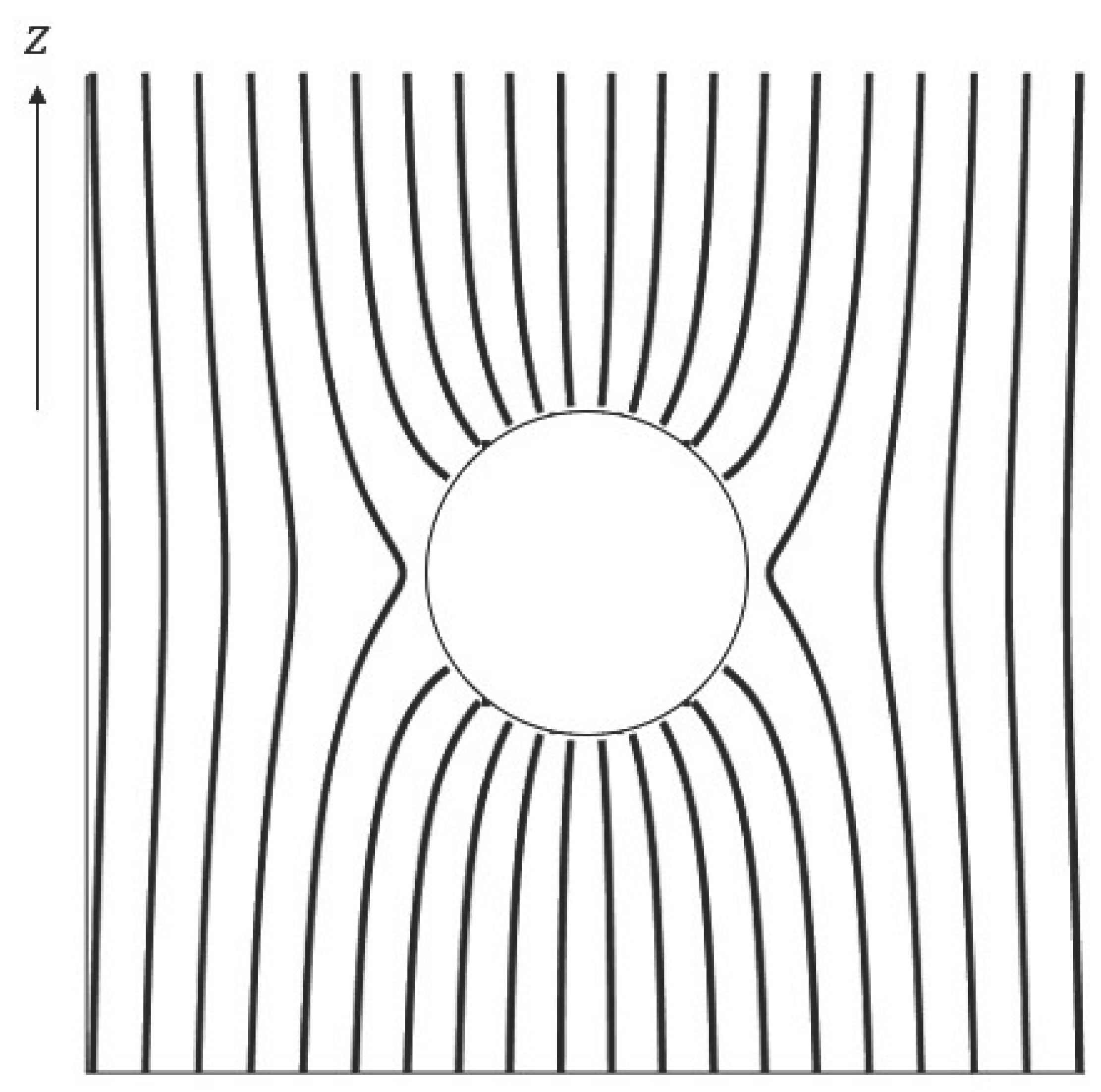
Figure 1 illustrates the electric field lines on a vertical plane (i.e., containing the
z axis) obtained from the electric field in (
17). As expected, far away from the sphere, the lines are vertical, while close by, they are “distorted” by the presence of the conductor. We also note that the field lines always enter and leave the sphere normally, and field abruptly drops to 0 as soon as we cross the boundary into the conductor. Finally, the field lines are seen to be the densest around the poles of the conductor (
), which can also be verified analytically from Equation (
17). An analytical derivation yields a maximum field strength of
2.2. Conducting Sphere Near a Point Charge
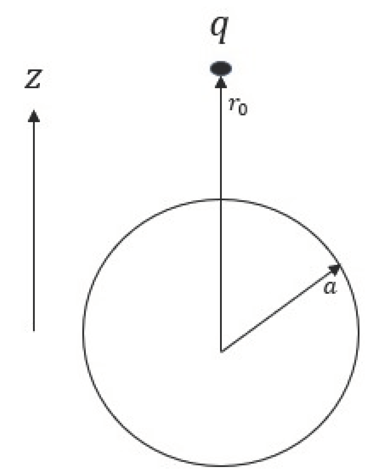
Consider a conducting sphere of radius
(with center at the origin) placed near a point charge
q located at
with
(see
Figure 2). Since the conducting sphere is an equipotential, let it be at potential
The overall potential
[
26] for
can be written as
where
is the potential due to the charge
q and
satisfies Laplace equation with appropriate boundary conditions.
To determine these boundary conditions, we note that the potential due to the charge
q at a point
on the sphere (assuming the boundary conditions
) is given by Coulomb’s law as
Therefore,
satisfies the boundary condition
Writing a trial solution
as
we observe that since we have the boundary conditions
we must have
for all
To obtain the coefficients
using (
18), we need the following lemma.
Lemma 4
converges absolutely for and and
Remark 2. The expansion (19) is the basis for the so-called “multi-pole” expansion (see, for example, [27]).
Since we have
and
we can use Lemma 4 to rewrite (
18) as
Therefore, by the uniqueness theorem (Lemma 2), the coefficients
are given by
The general solution
is thus given by
for
Equation (
23) can be written in a more illuminating form as
The overall potential is then given by
The potential (
25) is the same as that produced by the charge
q at
together with “virtual” charges
at
and
at the center of the conducting sphere [
28]. This can also be obtained through the so-called
method of images as used in many treatments of this topic [
15]. Equation (
25) also enables us to write the surface charge density on the sphere as
The charge density (
26) can be integrated to obtain the total charge on the sphere as
Writing
we have
We can then continue (
27) as
Equation (
29) is often interpreted (see, for example, [
15,
27]) as the sum of the
image charges and
2.3. Uniform Dielectric Sphere in Uniform Electric Field
Consider a sphere of radius
made of a
linear deielectric material of electric susceptibility
(with center at the origin) placed in a uniform electric field
Without loss of generality, let
We now wish to find the field both inside and outside the sphere. As we shall see later (cf. Remark 4), this situation can be thought of as a generalization to the problem studied in
Section 2.1. As argued in
Section 2.1, this problem exhibits azimuthal symmetry since the boundary conditions are independent of
We can then write trial solutions for the potentials inside and outside the sphere as
We will now discuss the boundary conditions to this problems, which are what will turn out to cause the crucial differences in the solutions for this case. First, as argued in
Section 2.1, the electric field must approach
as
and we therefore conclude that
for
and
Further, since the field inside the sphere is finite,
must have finite derivatives as
and (
30) then leads us to conclude that
for all
Equations (
30) and (31) then enable us to write down a global trial solution as
By the continuity of
V at the surface of the dielectric, the two expressions in (
32) must match at
Rearrangement leads to
Using the completeness of Legendre polynomials (Lemma 3) and noting that
Equation (
33) enables us to write
Finally, we come to the behavior of the electric field at the surface of the dielectric, which will yield additional boundary conditions and will be determined by the properties of the dielectric. The surface density of bound charges on the dielectric can be written as
This bound charge density, however, is
also given by the radial component of the polarization vector
i.e.,
Finally, since the material is a linear dielectric, we have
for
We therefore have
Equations (
37) and (
38) enable us to write
Using Lemma 3 again, the boundary condition (
39) enables us to write
For
(36) and (42) can simultaneously hold only if
Moreover, (35) and (41) enable us to solve for
as
i.e.,
This immediately yields
and we can finally write down the full solution (
32) as
The potential (
43) yields the electric field
The electric field inside can then be written as
which turns out to be uniform. The field outside can be written as
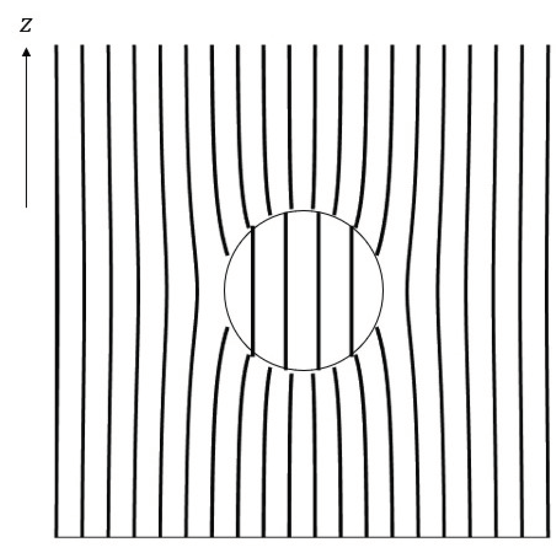
Figure 3 illustrates the electric field lines on a vertical plane (i.e., containing the
z axis) obtained from the electric field in (46) and (
44). As expected, far away from the sphere, the lines are vertical, while close by, they are “distorted” by the presence of the dielectric. We also note that there is a discontinuity of the field at the boundary of the dielectric, but unlike
Figure 1 in
Section 2.1, the field inside the dielectric is nonzero. Finally, the field lines are no longer orthogonal to the surface of the dielectric; the field can have a tangential component and electrostatic conditions can still be maintained.
Remark 3.
We note that the field when an uncharged conductor is placed in a uniform electric field (cf. (17) in Section 2.1) can also be written as
Both (48) and (45) can be compared to the field of a dipole placed at the origin (see, for example, [15]):
This suggests that a sphere made of a conductor or a linear dielectric material placed in an uniform electrostatic field acquires a dipole moment equal to
The polarization is defined as dipole moment per unit volume, therefore this suggests that the spheres acquire polarizations and The electric susceptibility therefore, can be interpreted as a parameter quantifying the amount of “freedom of movement” of charges inside a metrial – in a conductor they have perfect freedom of movement (i.e., ability to polarize), enabling complete cancellation of the electric field, but in a dielectric sphere, the polarization is times relative to a conductor.
Remark 4. We note that all results in Section 2.1 follow from those in this section by taking This shows that in electrostatics, in many situations a conductor can be thought of as a dielectric within infinite susceptibility. Taking this limit for (44) for the field inside the dielectric immediately recovers the result that the field is zero inside the conductor.
Remark 5. Note that in this section, we tacitly assumed that the dielectric is uncharged when we equated (37) and (38). The dielectric, in fact, could have a “free” surface charge density which would then have to be taken into account at that step. However, because charges cannot move about freely in a dielectric, unlike in a conductor, the complete charge density would have to be specified for this problem to have a unique solution.


